EP3734062B1 - Segmented blade, method for connecting segmented blades and wind power generator set - Google Patents
Segmented blade, method for connecting segmented blades and wind power generator set Download PDFInfo
- Publication number
- EP3734062B1 EP3734062B1 EP18893995.3A EP18893995A EP3734062B1 EP 3734062 B1 EP3734062 B1 EP 3734062B1 EP 18893995 A EP18893995 A EP 18893995A EP 3734062 B1 EP3734062 B1 EP 3734062B1
- Authority
- EP
- European Patent Office
- Prior art keywords
- blade
- clamping portion
- main spar
- segment
- blade segment
- Prior art date
- Legal status (The legal status is an assumption and is not a legal conclusion. Google has not performed a legal analysis and makes no representation as to the accuracy of the status listed.)
- Active
Links
Images


Classifications
-
- F—MECHANICAL ENGINEERING; LIGHTING; HEATING; WEAPONS; BLASTING
- F03—MACHINES OR ENGINES FOR LIQUIDS; WIND, SPRING, OR WEIGHT MOTORS; PRODUCING MECHANICAL POWER OR A REACTIVE PROPULSIVE THRUST, NOT OTHERWISE PROVIDED FOR
- F03D—WIND MOTORS
- F03D1/00—Wind motors with rotation axis substantially parallel to the air flow entering the rotor
- F03D1/06—Rotors
- F03D1/065—Rotors characterised by their construction elements
- F03D1/0675—Rotors characterised by their construction elements of the blades
-
- F—MECHANICAL ENGINEERING; LIGHTING; HEATING; WEAPONS; BLASTING
- F05—INDEXING SCHEMES RELATING TO ENGINES OR PUMPS IN VARIOUS SUBCLASSES OF CLASSES F01-F04
- F05B—INDEXING SCHEME RELATING TO WIND, SPRING, WEIGHT, INERTIA OR LIKE MOTORS, TO MACHINES OR ENGINES FOR LIQUIDS COVERED BY SUBCLASSES F03B, F03D AND F03G
- F05B2240/00—Components
- F05B2240/20—Rotors
- F05B2240/30—Characteristics of rotor blades, i.e. of any element transforming dynamic fluid energy to or from rotational energy and being attached to a rotor
- F05B2240/301—Cross-section characteristics
-
- F—MECHANICAL ENGINEERING; LIGHTING; HEATING; WEAPONS; BLASTING
- F05—INDEXING SCHEMES RELATING TO ENGINES OR PUMPS IN VARIOUS SUBCLASSES OF CLASSES F01-F04
- F05B—INDEXING SCHEME RELATING TO WIND, SPRING, WEIGHT, INERTIA OR LIKE MOTORS, TO MACHINES OR ENGINES FOR LIQUIDS COVERED BY SUBCLASSES F03B, F03D AND F03G
- F05B2240/00—Components
- F05B2240/20—Rotors
- F05B2240/30—Characteristics of rotor blades, i.e. of any element transforming dynamic fluid energy to or from rotational energy and being attached to a rotor
- F05B2240/302—Segmented or sectional blades
-
- F—MECHANICAL ENGINEERING; LIGHTING; HEATING; WEAPONS; BLASTING
- F05—INDEXING SCHEMES RELATING TO ENGINES OR PUMPS IN VARIOUS SUBCLASSES OF CLASSES F01-F04
- F05B—INDEXING SCHEME RELATING TO WIND, SPRING, WEIGHT, INERTIA OR LIKE MOTORS, TO MACHINES OR ENGINES FOR LIQUIDS COVERED BY SUBCLASSES F03B, F03D AND F03G
- F05B2250/00—Geometry
- F05B2250/20—Geometry three-dimensional
- F05B2250/29—Geometry three-dimensional machined; miscellaneous
- F05B2250/292—Geometry three-dimensional machined; miscellaneous tapered
-
- F—MECHANICAL ENGINEERING; LIGHTING; HEATING; WEAPONS; BLASTING
- F05—INDEXING SCHEMES RELATING TO ENGINES OR PUMPS IN VARIOUS SUBCLASSES OF CLASSES F01-F04
- F05B—INDEXING SCHEME RELATING TO WIND, SPRING, WEIGHT, INERTIA OR LIKE MOTORS, TO MACHINES OR ENGINES FOR LIQUIDS COVERED BY SUBCLASSES F03B, F03D AND F03G
- F05B2260/00—Function
- F05B2260/30—Retaining components in desired mutual position
-
- F—MECHANICAL ENGINEERING; LIGHTING; HEATING; WEAPONS; BLASTING
- F05—INDEXING SCHEMES RELATING TO ENGINES OR PUMPS IN VARIOUS SUBCLASSES OF CLASSES F01-F04
- F05B—INDEXING SCHEME RELATING TO WIND, SPRING, WEIGHT, INERTIA OR LIKE MOTORS, TO MACHINES OR ENGINES FOR LIQUIDS COVERED BY SUBCLASSES F03B, F03D AND F03G
- F05B2280/00—Materials; Properties thereof
- F05B2280/60—Properties or characteristics given to material by treatment or manufacturing
- F05B2280/6003—Composites; e.g. fibre-reinforced
-
- Y—GENERAL TAGGING OF NEW TECHNOLOGICAL DEVELOPMENTS; GENERAL TAGGING OF CROSS-SECTIONAL TECHNOLOGIES SPANNING OVER SEVERAL SECTIONS OF THE IPC; TECHNICAL SUBJECTS COVERED BY FORMER USPC CROSS-REFERENCE ART COLLECTIONS [XRACs] AND DIGESTS
- Y02—TECHNOLOGIES OR APPLICATIONS FOR MITIGATION OR ADAPTATION AGAINST CLIMATE CHANGE
- Y02E—REDUCTION OF GREENHOUSE GAS [GHG] EMISSIONS, RELATED TO ENERGY GENERATION, TRANSMISSION OR DISTRIBUTION
- Y02E10/00—Energy generation through renewable energy sources
- Y02E10/70—Wind energy
- Y02E10/72—Wind turbines with rotation axis in wind direction
Definitions
- the present application relates to the technical field of wind turbines, and particularly to a segmented blade, a method for forming a segmented blade, and a wind turbine.
- Wind turbines are used to convert wind energy into electrical energy.
- the length of the blade gradually increases.
- the gradually increasing length of the blade becomes a prominent problem that restricts the development of the wind turbines.
- EP 2746573A2 discloses methods of assembling rotor blades include providing a first blade segment comprising a first shell portion and at least two first spar cap segments and providing a second blade segment comprising a second shell portion and at least two second spar cap segments.
- An access region is defined in at least one of the first shell portion and the second shell portion.
- the second blade segment is then inserted into the first blade segment, such that a spar cap cavity is formed between each set of corresponding first and second spar cap segments, and wherein an access window is defined by the access region at an interface between the first blade segment and the second blade segment, the access window providing access to the spar cap cavities.
- the method further includes sealing the spar cap cavities and injecting an adhesive into the spar cap cavities to bond the blade segments together, wherein a scarf joint is formed between each set of corresponding first and second spar cap segments.
- EP2815861A1 discloses a method for producing a belt segment for a wind turbine rotor blade, and the wind turbine rotor blade comprises a longitudinal section, which has the belt segment, and at least one further longitudinal section which has a further Having belt segment, the belt segment being produced in a molding tool and having a connecting portion for connection to the further belt segment and the method comprising the following steps: a) providing a first molding tool part, b) arranging a first layer package of reinforcing fibers in the first molding tool part and arranging a second molding tool part, so that a first gap between the first molding tool part and the second molding tool part is formed, in which a part of the first layer package of the reinforcing fibers is arranged, c) arranging a second layer package from verse reinforcing fibers and arranging a third mold part, so that a second space is formed between the third mold part and the second mold part, in which a part of the second layer package of the reinforcing fibers is arranged, d)
- An object of the present application is to provide a segmented blade, which substantially do not increase the weight of the blade and has high reliability, a method of forming the segmented blade, and a wind turbine.
- a segmented blade includes a first blade segment having a first main spar, a second blade segment having a second main spar, and an outer shell.
- the first blade segment is close to a blade root
- the first main spar includes a first body portion arranged in the first blade segment and a first clamping portion extending from an end of the first body portion toward a direction away from a blade root, and a height of the first clamping portion is gradually decreased in the direction away from the blade root.
- the second blade segment is close to a blade tip
- the second main spar includes a second body portion arranged in the second blade segment and a second clamping portion extending from an end of the second body portion toward a direction getting close to the blade root, and a height of the second clamping portion is gradually increased in the direction getting close to the blade root.
- the second clamping portion is clamp-fitted into the first clamping portion.
- the outer shell is configured to encase a clearance between the first blade segment and the second blade segment.
- the first clamping portion is formed by extending any three of two main spar caps and two shear webs of the first main spar in the direction away from the blade root and the second blade segment is inserted chordwise into the first blade segment.
- a method of forming a segmented blade includes: providing a first blade segment having a first main spar, wherein the first blade segment is close to a blade root, the first main spar includes a first body portion arranged in the first blade segment and a first clamping portion extending from an end of the first body portion toward a direction away from the blade root, and a height of the first clamping portion is gradually decreased in the direction away from the blade root, and the first clamping portion is formed by extending any three of two main spar caps and two shear webs of the first main spar in the direction away from the blade root and the second blade segment is inserted chordwise into the first blade segment; providing a second blade segment having a second main spar, wherein the second blade segment is close to a blade tip, the second main spar includes a second body portion arranged in the second blade segment and a second clamping portion extending from an end of the second body portion toward a direction getting close to the blade root, and a height of the second clamping
- a wind turbine includes the above segmented blade.
- 1 blade, 2 main spar, 21 main spar cap, 22 shear web 100 first blade segment, 110 leading edge shell, 120 trailing edge shell, 130 first body portion, 140 first clamping portion, 150 first main spar, 151 main spar cap of the first main spar, 152 shear web of the first main spar, 153 gap, 200 second blade segment, 210 leading edge shell, 220 trailing edge shell, 230 second body portion, 240 second clamping portion, 250 second main spar, 251 main spar cap of the second main spar, 252 shear web of the second main spar, 300 reinforcing member, 400 outer shell.
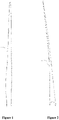
- Figure 1 is a schematic view of the shape of the conventional blade
- Figure 2 is a schematic view showing a main spar of the blade
- Figure 3 is a schematic view showing the main spar of the blade in Figure 2 in another direction.
- a wind turbine may include a blade 1 in Figure 1 . As shown in Figure 1 , the blade 1 becomes thinner and thinner from a blade root to a blade tip.
- a main spar 2 in Figures 2 and 3 may be arranged in the blade 1.
- the main spar 2 may include two main spar caps 21 and two shear webs 22. One of the two main spar caps 21 may be arranged at an upper housing of the blade 1, and the other of the two main spar caps 21 may be arranged at a lower housing of the blade 1.
- the two shear webs 22 are configured to support the two main spar caps 21 at two sides of the two main spar caps 21. As shown in Figure 3 , heights of the shear webs 22 become smaller and smaller, that is, a distance between the two main spar caps 21 becomes smaller and smaller. In addition, a distance between the two shear webs 22 may become smaller and smaller, or may be unchanged.
- a segmented blade according to an embodiment of the present application makes full use of a feature that the blade 1 shown in Figure 1 becomes thinner and thinner from the blade root to the blade tip, and the main spar 2 of the segmented blade is used for clamping and limiting connection.
- the segmented blade according to the embodiment of the present application will be described in detail with reference to Figures 4 to 13 .
- the segmented blade may include: a first blade segment 100 having a first main spar 150, wherein the first blade segment 100 is close to the blade root, the first main spar 150 includes a first body portion 130 arranged in the first blade segment 100 and a first clamping portion 140 extending from an end of the first body portion 130 toward a direction D1 away from the blade root, and a height of the first clamping portion 140 is gradually decreased in the direction D1 away from the blade root; a second blade segment 200 having a second main spar 250, wherein the second blade segment 200 is close to a blade tip, the second main spar 250 includes a second body portion 230 arranged in the second blade segment 200 and a second clamping portion 240 extending from an end of the second body portion 230 toward a direction D3 getting close to the blade root, and a height of the second clamping portion 240 is gradually increased in the direction D3 getting close to the blade root, where the second clamping portion 240 is clamp-fitted into the first clamping portion 140; and
- the first blade segment 100 may include a leading edge shell 110 and a trailing edge shell 120.
- An upper half housing of the leading edge shell 110 and an upper half housing of the trailing edge shell 120 may form an upper housing of the first blade segment 100
- a lower half housing of the leading edge shell 110 and a lower half housing of the trailing edge shell 120 may form a lower housing of the first blade segment 100.
- the first main spar 150 may include two main spar caps 151 and two shear webs 152, wherein the two main spar caps 151 may be arranged at the upper housing and the lower housing of the first blade segment 100, respectively, and the two shear webs 152 may be arranged at two sides of the two main spar caps 151 respectively, to support the two main spar caps 151.
- the first clamping portion 140 may be formed by extending any three of the two main spar caps 151 and the two shear webs 152 of the first main spar 150 in the direction D1 away from the blade root.
- Figures 4 and 5 shows an example in which the first clamping portion 140 is formed by extending the two main spar caps 151 and one shear web 152.
- the present application is not limited thereto, and the first clamping portion 140 may also be formed by extending one main spar cap 151 and the two shear webs 152.
- a gap 153 is formed in the first clamping portion 140 because one of the main spar caps 151 or one of the shear webs 152 is not extended.
- description will be made by taking a case that the gap 153 is formed because the shear web 152 is not extended as an example.
- the heights of the shear webs 22 are gradually decreased from the blade root to the blade tip of the blade 1. Therefore, according to the embodiment of the present application, as shown in Figure 6 , along the direction D1 away from the blade root, a height of the first clamping portion 140 in a thickness direction D2 of an airfoil (that is, the heights of the shear webs 152 in Figure 4 ) is gradually decreased. Therefore, in general, the first clamping portion 140 may be formed in a tubular shape having an opening gradually decreasing in the direction D1 away from the blade root and having the gap 153.
- each of the main spar caps 151 of the first clamping portion 140 may be concaved with respect to an extension line of the corresponding main spar cap 151 in the first body portion 130, to form a first step t1 between the first clamping portion 140 and the first body portion 130, and a height of the first step t1 may range from 6 mm to 10 mm.
- each of the main spar caps 151 of the first clamping portion 140 may be concaved by an amount of the first step t1 in the thickness direction D2 of the airfoil, that is, each of the main spar caps 151 of the first clamping portion 140 may be concaved by the amount of the first step t1 with respect to the design of an original main spar cap, thereby providing a space for the subsequent process of winding a reinforcing member 300 (described in detail below).
- the second blade segment 200 may include a leading edge shell 210 and a trailing edge shell 220.
- An upper half housing of the leading edge shell 210 and an upper half housing of the trailing edge shell 220 may form an upper housing of the second blade segment 200, and a lower half housing of the leading edge shell 210 and a lower half housing of the trailing edge shell 220 may form a lower housing of the second blade segment 200.
- the second main spar 250 may include two main spar caps 251 and two shear webs 252, wherein the two main spar caps 251 may be arranged at the upper housing and the lower housing of the second blade segment 200, respectively, and the two shear webs 252 may be arranged at two sides of the two main spar caps 251 respectively, to support the two main spar caps 251.
- the second clamping portion 240 may be formed by extending the two main spar caps 251 and the two shear webs 252.
- the present application is not limited thereto.
- the second clamping portion 240 may also be formed by extending any three of the two main spar caps 251 and the two shear webs 252. An example in which the second clamping portion 240 is formed by extending the two main spar caps 251 and the two shear webs 252 will be described hereinafter.
- the height of the second clamping portion 240 in the thickness direction D2 of the airfoil becomes greater and greater in the direction D3 getting close to the blade root.
- each of the two main spar caps 251 in the second clamping portion 240 is concaved with respect to an extension line of the corresponding main spar cap 251 in the second body portion 230, to form a second step t2 between the second clamping portion 240 and the second body portion 230, where a height of the second step t2 is equal to a sum of the height of the first step t1 and a thickness of the main spar cap 151 of the first main spar 150.
- the two shear webs 252 of the second clamping portion 240 offset respectively, in a direction allowing the two shear webs 252 to get close to each other, by a predetermined distance with respect to extension lines of the shear webs 252 of the second body portion 230, and the predetermined distance is a thickness of a shear web 152 of the first main spar 150.
- each of the two main spar caps 251 in the second clamping portion 240 is concaved by the second step t2 in a direction allowing the two main spar caps 251 to get close to each other.
- shear webs 252 in the second clamping portion 240 are manufactured according to the design of the original main spar, dimensions of the shear webs 252 in the second clamping portion 240 and dimensions of the shear webs 152 in the first clamping portion 140 in a chord direction of the blade are identical to each other.
- the two shear webs 252 of the second clamping portion 240 may offset respectively, in the direction allowing the two shear webs 252 to get close to each other, by the predetermined distance with respect to extension lines of the shear webs 252 of the second body portion 230, and the predetermined distance may be the thickness of the shear web 152.
- thicknesses of the main spar caps 151 of the clamping portion 140 are gradually decreased in the direction D1 away from the blade root, and thicknesses of the main spar caps 251 of the second clamping portion 240 are gradually decreased in the direction D3 getting close to the blade root.
- thicknesses of the shear webs 152 of the first clamping portion 140 may also be gradually decreased in the direction D1 away from the blade root, and thicknesses of the shear webs 252 of the second clamping portion 240 may also be gradually decreased in the direction D3 getting close to the blade root, to reduce the stress when the first clamping portion 140 and the second clamping portion 240 are clamp-fitted to each other.
- the main spar caps 151 of the first clamping portion 140 may have flat inner surfaces
- the main spar caps 251 of the second clamping portion 240 may have flat outer surfaces.
- the main spar caps 151 in the first main spar 150 and the main spar caps 251 in the second main spar 250 may be arc-shaped. Therefore, when the first main spar 150 and the second main spar 250 are manufactured, the inner surfaces of the main spar caps 151 in the first clamping portion 140 and the outer surfaces of the main spar caps 251 in the second clamping portion 240 may be flattened, to avoid a gap between the main spar caps 151 in the first clamping portion 140 and the main spar caps 251 in the second clamping portion 240 during assembly.
- lengths of the first clamping portion 140 and the second clamping portion 240 may be determined according to the shape and load of the blade, which are not specifically limited. In an example, the lengths of the first clamping portion 140 and the second clamping portion 240 may range from 0.5 m to 5 m.
- the second clamping portion 240 in Figure 8 may be clamp-fitted into the first clamping portion 140 through the gap 153 of the first clamping portion 140 in Figure 5 . That is, the second clamping portion 240 in Figure 8 may enter the first clamping portion 140 from the gap 153 in Figure 5 in a chord direction of the first blade segment 100, and thus is clamp-fitted into the first clamping portion 140.
- the two main spar caps 251 of the second clamping portion 240 may be abutted against the two main spar caps 151 of the first clamping portion 140 respectively (as shown in Figure10 ), and one of the shear webs 252 of the second clamping portion 240 may be abutted against the shear web 152 of the first clamping portion 140 in Figure 5 .
- a gap may also be formed in a case that one of the spar caps 151 is not allowed to extend.
- the second clamping portion 240 may enter the first clamping portion 140 from the gap in the thickness direction D2 of the airfoil of the first blade segment 100, and thus is clamp-fitted into the first clamping portion 140.
- the segmented blade may further include a filling member (not shown), which may be used to fill the gap 153.
- a filling member (not shown), which may be used to fill the gap 153.
- the filling member may be formed by a material same as that of the shear web 152, to fill the gap 153, so as to ensure the reliability of the blade.
- the filling member may be formed by a material same as that of the spar cap 151, to fill the gap.
- the segmented blade may further include a reinforcing member 300, as shown in Figure 10 .
- the reinforcing member 300 may be wound around an outer periphery of the first clamping portion 140, to achieve smooth transition between the first main spar 150 and the second main spar 250.
- the reinforcing member 300 may be an insulating material, so as to prevent lightning strikes.
- the reinforcing member 300 may be a reinforcing material impregnated with resin (not shown), so as to provide a stronger fastening force.
- the reinforcing material may be a fiberglass cloth, such as a triaxial fiberglass cloth.
- the present application is not limited thereto, and the reinforcing member 300 may be other string-like members.
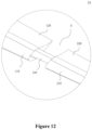
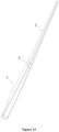
- the outer shell 400 (as shown in Figure 13 ) may be configure to encase the clearance G between the first blade segment 100 and the second blade segment 200 (as shown in Figure 12 ).
- a first bonding angle and a second bonding angle may be formed at a portion of the first blade segment 100 and a portion of the second blade segment 200 adjacent to each other, respectively; the first bonding angle is formed by concaving the first blade segment 100 inwardly, and the second bonding angle is formed by concaving the second blade segment 200 inwardly.
- the outer shell 400 may be covered on the first bonding angle and the second bonding angle, to allow the first bonding angle and the second bonding angle to be flush with other portions of the segmented blade.
- the outer shell 400 may be adhered to the first bonding angle and the second bonding angle by a liquid structural adhesive, and then the structural adhesive is cured.
- seams between the outer shell 400 and the first blade segment 100 and between the outer shell 400 and the second blade segment 200 may be reinforced.
- the reinforcing material such as the fiberglass cloth may be laid at the seams between the outer shell 400 and the first blade segment 100 and between the outer shell 400 and the second blade segment 200, and then the resin is poured; or, the reinforcing material impregnated with the resin may be directly laid to form a reinforcing layer for reinforcement.
- a reinforcing area may be polished and sprayed with a surface protective layer, and a segmented position may be sprayed with a pigment having a color different from that of a surface of the blade, so as to facilitate subsequent inspection of the blade.
- segmented blade according to the present application is described hereinbefore by taking a segmented blade including two blade segments as an example, the present application is not limited thereto, and the segmented blade may include three or more blade segments, wherein two adjacent blade segments may be connected to each other by the above-described manner of connecting through a main spar.
- a wind turbine may be provided.
- the wind turbine may include the segmented blade as described above.
- the segmented blade according to the present application makes use of a feature that the blade becomes thinner and thinner from the blade root to the blade tip, and the blade segments may be clamp-fitted together by the main spar.
- the segmented blade according to the present application substantially does not increase the weight of the blade, therefore, a load in an oscillation direction and a fatigue load of the blade can be reduced, and the inconvenience that pre-tightening is required in the bolted connection can be avoided.
- a distance between the main spar caps of the main spar becomes smaller and smaller in the direction from the blade root to the blade tip, therefore, the blade segment close to the blade tip does not come out of the blade segment close to the blade root, and thus the connection reliability is higher.
- a fastener (the reinforcing material impregnated with the resin is preferably employed) can be employed to wind a portion where the two clamping portions are clamp-fitted to each other, and thus the reliability of the clamping connection between the main spars of the two blade segments clamp-fitted to each other can be further improved.
- the number of bolts is limited in the bolted connection, therefore, it cannot be realized that the blade can be segmented at any position.
- the blade can be segmented at any position, and therefore a degree of freedom of segmentation is increased.
Landscapes
- Engineering & Computer Science (AREA)
- Life Sciences & Earth Sciences (AREA)
- Sustainable Development (AREA)
- Sustainable Energy (AREA)
- Chemical & Material Sciences (AREA)
- Combustion & Propulsion (AREA)
- Mechanical Engineering (AREA)
- General Engineering & Computer Science (AREA)
- Wind Motors (AREA)
Description
- The present application relates to the technical field of wind turbines, and particularly to a segmented blade, a method for forming a segmented blade, and a wind turbine.
- Wind turbines are used to convert wind energy into electrical energy. At present, with the increase of the megawatt level of the wind turbines, the length of the blade gradually increases. For the manufacture and transportation of the blade, the gradually increasing length of the blade becomes a prominent problem that restricts the development of the wind turbines.
-
EP 2746573A2 discloses methods of assembling rotor blades include providing a first blade segment comprising a first shell portion and at least two first spar cap segments and providing a second blade segment comprising a second shell portion and at least two second spar cap segments. An access region is defined in at least one of the first shell portion and the second shell portion. The second blade segment is then inserted into the first blade segment, such that a spar cap cavity is formed between each set of corresponding first and second spar cap segments, and wherein an access window is defined by the access region at an interface between the first blade segment and the second blade segment, the access window providing access to the spar cap cavities. The method further includes sealing the spar cap cavities and injecting an adhesive into the spar cap cavities to bond the blade segments together, wherein a scarf joint is formed between each set of corresponding first and second spar cap segments. -
EP2815861A1 discloses a method for producing a belt segment for a wind turbine rotor blade, and the wind turbine rotor blade comprises a longitudinal section, which has the belt segment, and at least one further longitudinal section which has a further Having belt segment, the belt segment being produced in a molding tool and having a connecting portion for connection to the further belt segment and the method comprising the following steps: a) providing a first molding tool part, b) arranging a first layer package of reinforcing fibers in the first molding tool part and arranging a second molding tool part, so that a first gap between the first molding tool part and the second molding tool part is formed, in which a part of the first layer package of the reinforcing fibers is arranged, c) arranging a second layer package from verse reinforcing fibers and arranging a third mold part, so that a second space is formed between the third mold part and the second mold part, in which a part of the second layer package of the reinforcing fibers is arranged, d) curing a plastic material surrounding the reinforcing fibers, and e) removing the belt segment from the mold, the first and second intermediate spaces being shaped and arranged relative to one another in such a way that the sections of the belt segment manufactured therein reach the connecting section for connection to the other Form the connecting section of the further belt segment. - An object of the present application is to provide a segmented blade, which substantially do not increase the weight of the blade and has high reliability, a method of forming the segmented blade, and a wind turbine.
- According to an aspect of the present application, a segmented blade is provided. The segmented blade includes a first blade segment having a first main spar, a second blade segment having a second main spar, and an outer shell. The first blade segment is close to a blade root, the first main spar includes a first body portion arranged in the first blade segment and a first clamping portion extending from an end of the first body portion toward a direction away from a blade root, and a height of the first clamping portion is gradually decreased in the direction away from the blade root. The second blade segment is close to a blade tip, the second main spar includes a second body portion arranged in the second blade segment and a second clamping portion extending from an end of the second body portion toward a direction getting close to the blade root, and a height of the second clamping portion is gradually increased in the direction getting close to the blade root. The second clamping portion is clamp-fitted into the first clamping portion. The outer shell is configured to encase a clearance between the first blade segment and the second blade segment. The first clamping portion is formed by extending any three of two main spar caps and two shear webs of the first main spar in the direction away from the blade root and the second blade segment is inserted chordwise into the first blade segment.
- According to another aspect of the present application, a method of forming a segmented blade is provided. The method includes: providing a first blade segment having a first main spar, wherein the first blade segment is close to a blade root, the first main spar includes a first body portion arranged in the first blade segment and a first clamping portion extending from an end of the first body portion toward a direction away from the blade root, and a height of the first clamping portion is gradually decreased in the direction away from the blade root, and the first clamping portion is formed by extending any three of two main spar caps and two shear webs of the first main spar in the direction away from the blade root and the second blade segment is inserted chordwise into the first blade segment; providing a second blade segment having a second main spar, wherein the second blade segment is close to a blade tip, the second main spar includes a second body portion arranged in the second blade segment and a second clamping portion extending from an end of the second body portion toward a direction getting close to the blade root, and a height of the second clamping portion is gradually increased in the direction getting close to the blade root; clamp-fitting the second clamping portion into the first clamping portion; and encasing, by an outer shell, a clearance between the first blade segment and the second blade segment.
- According to yet another aspect of the present application, a wind turbine is provided. The wind turbine includes the above segmented blade.
- Through the following detailed description in conjunction with the drawings, the above and other objects, features and advantages of the present application will become more apparent.
-
Figure 1 is a schematic view of an outline of a conventional blade; -
Figure 2 is a schematic view showing a main spar of the blade; -
Figure 3 is a schematic view showing the main spar of the blade inFigure 2 in another direction; -
Figure 4 is a schematic view showing a first blade segment according to an embodiment of the present application; -
Figure 5 is an enlarged schematic view showing a portion P1 of the first blade segment inFigure 4 ; -
Figure 6 is a schematic view showing a first main spar of the first blade segment inFigure 4 ; -
Figure 7 is a schematic view showing a second blade segment according to the embodiment of the present application; -
Figure 8 is an enlarged schematic view showing a portion P2 of the second blade segment inFigure 7 ; -
Figure 9 is a schematic view showing a second main spar of the second blade segment inFigure 7 ; -
Figure 10 is a schematic view showing that the first main spar inFigure 6 and the second main spar inFigure 9 are connected; -
Figure 11 is a schematic view showing that the first blade segment inFigure 5 and the second blade segment inFigure 7 are connected; -
Figure 12 is an enlarged schematic view showing a portion P3 inFigure 11 ; and -
Figure 13 is a schematic view showing that a clearance between the first blade segment and the second blade segment is encased by using an outer shell. -
Reference Numerals: 1 blade, 2 main spar, 21 main spar cap, 22 shear web, 100 first blade segment, 110 leading edge shell, 120 trailing edge shell, 130 first body portion, 140 first clamping portion, 150 first main spar, 151 main spar cap of the first main spar, 152 shear web of the first main spar, 153 gap, 200 second blade segment, 210 leading edge shell, 220 trailing edge shell, 230 second body portion, 240 second clamping portion, 250 second main spar, 251 main spar cap of the second main spar, 252 shear web of the second main spar, 300 reinforcing member, 400 outer shell. - First, a shape of a conventional blade will be described with reference to
Figures 1 to 3 .Figure 1 is a schematic view of the shape of the conventional blade,Figure 2 is a schematic view showing a main spar of the blade, andFigure 3 is a schematic view showing the main spar of the blade inFigure 2 in another direction. - A wind turbine may include a
blade 1 inFigure 1 . As shown inFigure 1 , theblade 1 becomes thinner and thinner from a blade root to a blade tip. A main spar 2 inFigures 2 and3 may be arranged in theblade 1. The main spar 2 may include twomain spar caps 21 and twoshear webs 22. One of the twomain spar caps 21 may be arranged at an upper housing of theblade 1, and the other of the twomain spar caps 21 may be arranged at a lower housing of theblade 1. The twoshear webs 22 are configured to support the twomain spar caps 21 at two sides of the twomain spar caps 21. As shown inFigure 3 , heights of theshear webs 22 become smaller and smaller, that is, a distance between the twomain spar caps 21 becomes smaller and smaller. In addition, a distance between the twoshear webs 22 may become smaller and smaller, or may be unchanged. - A segmented blade according to an embodiment of the present application makes full use of a feature that the
blade 1 shown inFigure 1 becomes thinner and thinner from the blade root to the blade tip, and the main spar 2 of the segmented blade is used for clamping and limiting connection. Hereinafter, the segmented blade according to the embodiment of the present application will be described in detail with reference toFigures 4 to 13 . - As shown in
Figures 4 to 13 , the segmented blade may include: afirst blade segment 100 having a firstmain spar 150, wherein thefirst blade segment 100 is close to the blade root, the firstmain spar 150 includes afirst body portion 130 arranged in thefirst blade segment 100 and afirst clamping portion 140 extending from an end of thefirst body portion 130 toward a direction D1 away from the blade root, and a height of thefirst clamping portion 140 is gradually decreased in the direction D1 away from the blade root; asecond blade segment 200 having a secondmain spar 250, wherein thesecond blade segment 200 is close to a blade tip, the secondmain spar 250 includes asecond body portion 230 arranged in thesecond blade segment 200 and asecond clamping portion 240 extending from an end of thesecond body portion 230 toward a direction D3 getting close to the blade root, and a height of thesecond clamping portion 240 is gradually increased in the direction D3 getting close to the blade root, where thesecond clamping portion 240 is clamp-fitted into thefirst clamping portion 140; and anouter shell 400 configured to encase a clearance G between thefirst blade segment 100 and thesecond blade segment 200. - As shown in
Figures 4 to 6 , at a side of thefirst blade segment 100 close to the blade root, thefirst blade segment 100 may include a leadingedge shell 110 and atrailing edge shell 120. An upper half housing of the leadingedge shell 110 and an upper half housing of thetrailing edge shell 120 may form an upper housing of thefirst blade segment 100, and a lower half housing of the leadingedge shell 110 and a lower half housing of thetrailing edge shell 120 may form a lower housing of thefirst blade segment 100. - The first
main spar 150 may include twomain spar caps 151 and twoshear webs 152, wherein the twomain spar caps 151 may be arranged at the upper housing and the lower housing of thefirst blade segment 100, respectively, and the twoshear webs 152 may be arranged at two sides of the twomain spar caps 151 respectively, to support the twomain spar caps 151. - Optionally, the
first clamping portion 140 may be formed by extending any three of the twomain spar caps 151 and the twoshear webs 152 of the firstmain spar 150 in the direction D1 away from the blade root. -
Figures 4 and5 shows an example in which thefirst clamping portion 140 is formed by extending the twomain spar caps 151 and oneshear web 152. However, the present application is not limited thereto, and thefirst clamping portion 140 may also be formed by extending onemain spar cap 151 and the twoshear webs 152. Agap 153 is formed in thefirst clamping portion 140 because one of themain spar caps 151 or one of theshear webs 152 is not extended. Hereinafter, description will be made by taking a case that thegap 153 is formed because theshear web 152 is not extended as an example. - Referring to
Figures 1 and3 , the heights of theshear webs 22 are gradually decreased from the blade root to the blade tip of theblade 1. Therefore, according to the embodiment of the present application, as shown inFigure 6 , along the direction D1 away from the blade root, a height of thefirst clamping portion 140 in a thickness direction D2 of an airfoil (that is, the heights of theshear webs 152 inFigure 4 ) is gradually decreased. Therefore, in general, thefirst clamping portion 140 may be formed in a tubular shape having an opening gradually decreasing in the direction D1 away from the blade root and having thegap 153. - In addition, as shown in
Figure 6 , according the embodiment of the present application, each of the main spar caps 151 of thefirst clamping portion 140 may be concaved with respect to an extension line of the correspondingmain spar cap 151 in thefirst body portion 130, to form a first step t1 between thefirst clamping portion 140 and thefirst body portion 130, and a height of the first step t1 may range from 6 mm to 10 mm. - When the first
main spar 150 is manufactured, each of the main spar caps 151 of thefirst clamping portion 140 may be concaved by an amount of the first step t1 in the thickness direction D2 of the airfoil, that is, each of the main spar caps 151 of thefirst clamping portion 140 may be concaved by the amount of the first step t1 with respect to the design of an original main spar cap, thereby providing a space for the subsequent process of winding a reinforcing member 300 (described in detail below). - As shown in
Figures 7 to 9 , at a side of thesecond blade segment 200 close to the blade root, thesecond blade segment 200 may include aleading edge shell 210 and a trailingedge shell 220. An upper half housing of theleading edge shell 210 and an upper half housing of the trailingedge shell 220 may form an upper housing of thesecond blade segment 200, and a lower half housing of theleading edge shell 210 and a lower half housing of the trailingedge shell 220 may form a lower housing of thesecond blade segment 200. - The second
main spar 250 may include two main spar caps 251 and twoshear webs 252, wherein the two main spar caps 251 may be arranged at the upper housing and the lower housing of thesecond blade segment 200, respectively, and the twoshear webs 252 may be arranged at two sides of the two main spar caps 251 respectively, to support the two main spar caps 251. - Considering the clamping stability between the
second clamping portion 240 and thefirst clamping portion 140 and the stability of the blade after the segmented blade is formed, preferably, thesecond clamping portion 240 may be formed by extending the two main spar caps 251 and the twoshear webs 252. However, the present application is not limited thereto. Similar to thefirst clamping portion 140, thesecond clamping portion 240 may also be formed by extending any three of the two main spar caps 251 and the twoshear webs 252. An example in which thesecond clamping portion 240 is formed by extending the two main spar caps 251 and the twoshear webs 252 will be described hereinafter. - According to the embodiment of the present application, as shown in
Figure 9 , the height of thesecond clamping portion 240 in the thickness direction D2 of the airfoil becomes greater and greater in the direction D3 getting close to the blade root. - In addition, according to the embodiment of the present application, as shown in
Figure 9 , each of the two main spar caps 251 in thesecond clamping portion 240 is concaved with respect to an extension line of the correspondingmain spar cap 251 in thesecond body portion 230, to form a second step t2 between thesecond clamping portion 240 and thesecond body portion 230, where a height of the second step t2 is equal to a sum of the height of the first step t1 and a thickness of themain spar cap 151 of the firstmain spar 150. In addition, the twoshear webs 252 of thesecond clamping portion 240 offset respectively, in a direction allowing the twoshear webs 252 to get close to each other, by a predetermined distance with respect to extension lines of theshear webs 252 of thesecond body portion 230, and the predetermined distance is a thickness of ashear web 152 of the firstmain spar 150. - In a case that the main spar caps 251 in the
second clamping portion 240 are manufactured according to the design of the original main spar, when thesecond clamping portion 240 is to be clamp-fitted into thefirst clamping portion 140, the main spar caps 251 in thesecond clamping portion 240 and the main spar caps 151 in thefirst clamping portion 140 may get stuck, and thus thesecond clamping portion 240 cannot be clamp-fitted into thefirst clamping portion 140. Therefore, according to the embodiment of the present application, when the secondmain spar 250 is manufactured, each of the two main spar caps 251 in thesecond clamping portion 240 is concaved by the second step t2 in a direction allowing the two main spar caps 251 to get close to each other. - In addition, if the
shear webs 252 in thesecond clamping portion 240 are manufactured according to the design of the original main spar, dimensions of theshear webs 252 in thesecond clamping portion 240 and dimensions of theshear webs 152 in thefirst clamping portion 140 in a chord direction of the blade are identical to each other. In order to avoid interference between theshear webs 252 and theshear webs 152 in a case that thesecond clamping portion 240 is clamp-fitted into thefirst clamping portion 140, the twoshear webs 252 of thesecond clamping portion 240 may offset respectively, in the direction allowing the twoshear webs 252 to get close to each other, by the predetermined distance with respect to extension lines of theshear webs 252 of thesecond body portion 230, and the predetermined distance may be the thickness of theshear web 152. - According to the embodiment of the present application, in order to reduce stress when the
first clamping portion 140 and thesecond clamping portion 240 are clamp-fitted to each other, as shown inFigure 6 andFigure 9 , thicknesses of the main spar caps 151 of the clampingportion 140 are gradually decreased in the direction D1 away from the blade root, and thicknesses of the main spar caps 251 of thesecond clamping portion 240 are gradually decreased in the direction D3 getting close to the blade root. In addition, thicknesses of theshear webs 152 of thefirst clamping portion 140 may also be gradually decreased in the direction D1 away from the blade root, and thicknesses of theshear webs 252 of thesecond clamping portion 240 may also be gradually decreased in the direction D3 getting close to the blade root, to reduce the stress when thefirst clamping portion 140 and thesecond clamping portion 240 are clamp-fitted to each other. - In addition, according to the embodiment of the present application, the main spar caps 151 of the
first clamping portion 140 may have flat inner surfaces, and the main spar caps 251 of thesecond clamping portion 240 may have flat outer surfaces. Specifically, due to a shape of the blade, the main spar caps 151 in the firstmain spar 150 and the main spar caps 251 in the secondmain spar 250 may be arc-shaped. Therefore, when the firstmain spar 150 and the secondmain spar 250 are manufactured, the inner surfaces of the main spar caps 151 in thefirst clamping portion 140 and the outer surfaces of the main spar caps 251 in thesecond clamping portion 240 may be flattened, to avoid a gap between the main spar caps 151 in thefirst clamping portion 140 and the main spar caps 251 in thesecond clamping portion 240 during assembly. - In addition, according to the embodiment of the present application, lengths of the
first clamping portion 140 and thesecond clamping portion 240 may be determined according to the shape and load of the blade, which are not specifically limited. In an example, the lengths of thefirst clamping portion 140 and thesecond clamping portion 240 may range from 0.5 m to 5 m. - The
second clamping portion 240 inFigure 8 may be clamp-fitted into thefirst clamping portion 140 through thegap 153 of thefirst clamping portion 140 inFigure 5 . That is, thesecond clamping portion 240 inFigure 8 may enter thefirst clamping portion 140 from thegap 153 inFigure 5 in a chord direction of thefirst blade segment 100, and thus is clamp-fitted into thefirst clamping portion 140. In a clamp-fitting state, the two main spar caps 251 of thesecond clamping portion 240 may be abutted against the two main spar caps 151 of thefirst clamping portion 140 respectively (as shown inFigure10 ), and one of theshear webs 252 of thesecond clamping portion 240 may be abutted against theshear web 152 of thefirst clamping portion 140 inFigure 5 . - As described above, a gap may also be formed in a case that one of the spar caps 151 is not allowed to extend. In this case, the
second clamping portion 240 may enter thefirst clamping portion 140 from the gap in the thickness direction D2 of the airfoil of thefirst blade segment 100, and thus is clamp-fitted into thefirst clamping portion 140. - According to the embodiment of the present application, the segmented blade may further include a filling member (not shown), which may be used to fill the
gap 153. For example, as shown inFigure 5 , in a case that thegap 153 is formed by ashear web 152 which is not allowed to extend, the filling member may be formed by a material same as that of theshear web 152, to fill thegap 153, so as to ensure the reliability of the blade. In addition, it should be understood that, in a case that the gap is formed by aspar cap 151 which is not allowed to extend, the filling member may be formed by a material same as that of thespar cap 151, to fill the gap. - According to the embodiment of the present application, in order to further ensure the stability of the clamping connection between the
second clamping portion 240 and thefirst clamping portion 140, the segmented blade may further include a reinforcingmember 300, as shown inFigure 10 . For example, after thegap 153 is filled by the filling member, the reinforcingmember 300 may be wound around an outer periphery of thefirst clamping portion 140, to achieve smooth transition between the firstmain spar 150 and the secondmain spar 250. - The reinforcing
member 300 may be an insulating material, so as to prevent lightning strikes. Preferably, the reinforcingmember 300 may be a reinforcing material impregnated with resin (not shown), so as to provide a stronger fastening force. Optionally, the reinforcing material may be a fiberglass cloth, such as a triaxial fiberglass cloth. However, the present application is not limited thereto, and the reinforcingmember 300 may be other string-like members. - According to the embodiment of the present application, the outer shell 400 (as shown in
Figure 13 ) may be configure to encase the clearance G between thefirst blade segment 100 and the second blade segment 200 (as shown inFigure 12 ). - Specifically, a first bonding angle and a second bonding angle may be formed at a portion of the
first blade segment 100 and a portion of thesecond blade segment 200 adjacent to each other, respectively; the first bonding angle is formed by concaving thefirst blade segment 100 inwardly, and the second bonding angle is formed by concaving thesecond blade segment 200 inwardly. Theouter shell 400 may be covered on the first bonding angle and the second bonding angle, to allow the first bonding angle and the second bonding angle to be flush with other portions of the segmented blade. For example, theouter shell 400 may be adhered to the first bonding angle and the second bonding angle by a liquid structural adhesive, and then the structural adhesive is cured. - According to the embodiment of the present application, on the basis of ensuring an aerodynamic shape of the blade, seams between the
outer shell 400 and thefirst blade segment 100 and between theouter shell 400 and thesecond blade segment 200 may be reinforced. For example, the reinforcing material such as the fiberglass cloth may be laid at the seams between theouter shell 400 and thefirst blade segment 100 and between theouter shell 400 and thesecond blade segment 200, and then the resin is poured; or, the reinforcing material impregnated with the resin may be directly laid to form a reinforcing layer for reinforcement. - In addition, a reinforcing area may be polished and sprayed with a surface protective layer, and a segmented position may be sprayed with a pigment having a color different from that of a surface of the blade, so as to facilitate subsequent inspection of the blade.
- It should be understood that, although the segmented blade according to the present application is described hereinbefore by taking a segmented blade including two blade segments as an example, the present application is not limited thereto, and the segmented blade may include three or more blade segments, wherein two adjacent blade segments may be connected to each other by the above-described manner of connecting through a main spar.
- According to another embodiment of the present application, a wind turbine may be provided. The wind turbine may include the segmented blade as described above.
- As described above, the segmented blade according to the present application makes use of a feature that the blade becomes thinner and thinner from the blade root to the blade tip, and the blade segments may be clamp-fitted together by the main spar. Compared with the bolted connection, the segmented blade according to the present application substantially does not increase the weight of the blade, therefore, a load in an oscillation direction and a fatigue load of the blade can be reduced, and the inconvenience that pre-tightening is required in the bolted connection can be avoided. In addition, compared with the structural adhesive connection, a distance between the main spar caps of the main spar becomes smaller and smaller in the direction from the blade root to the blade tip, therefore, the blade segment close to the blade tip does not come out of the blade segment close to the blade root, and thus the connection reliability is higher.
- In addition, according to the embodiment of the present application, a fastener (the reinforcing material impregnated with the resin is preferably employed) can be employed to wind a portion where the two clamping portions are clamp-fitted to each other, and thus the reliability of the clamping connection between the main spars of the two blade segments clamp-fitted to each other can be further improved.
- Furthermore, the number of bolts is limited in the bolted connection, therefore, it cannot be realized that the blade can be segmented at any position. However, according to the segmented blade of the present application, the blade can be segmented at any position, and therefore a degree of freedom of segmentation is increased.
- In addition, a manner such as plug connection or bolted connection or the like is usually employed between conventional blade segments, and metal materials are inevitably used, which not only increases the weight of the blade itself, but also may cause lightning strikes. However, according to the segmented blade of the present application, the blade segments are directly connected by insulating materials, so that the blade is light-weight and lightning strikes can be avoided.
Claims (14)
- A segmented blade, comprising:a first blade segment (100) having a first main spar (150), wherein the first blade segment (100) is close to a blade root, the first main spar (150) comprises a first body portion (130) arranged in the first blade segment (100) and a first clamping portion (140) extending from an end of the first body portion (130) toward a direction (D1) away from a blade root, and a height of the first clamping portion (140) is gradually decreased in the direction (D1) away from the blade root;a second blade segment (200) having a second main spar (250), wherein the second blade segment (200) is close to a blade tip, the second main spar (250) comprises a second body portion (230) arranged in the second blade segment (200) and a second clamping portion (240) extending from an end of the second body portion (230) toward a direction (D3) getting close to the blade root, a height of the second clamping portion (240) is gradually increased in the direction (D3) getting close to the blade root, and the second clamping portion (240) is clamp-fitted into the first clamping portion (140); andan outer shell (400) configured to encase a clearance (G) between the first blade segment (100) and the second blade segment (200),characterized in that, the first clamping portion (140) is formed by extending any three of two main spar caps (151) and two shear webs (152) of the first main spar (150) in the direction (D1) away from the blade root and the second blade segment (200) is inserted chordwise into the first blade segment (100).
- The segmented blade according to claim 1, wherein each of the main spar caps (151) in the first clamping portion (140) is concaved with respect to an extension line of the corresponding main spar cap (151) in the first body portion (130), to form a first step between the first clamping portion (140) and the first body portion (130).
- The segmented blade according to claim 2, wherein the second clamping portion (240) is formed by extending two main spar caps (251) and two shear webs (252) of the second main spar (250) in the direction (D3) getting close to the blade root.
- The segmented blade according to claim 3, wherein each of the two main spar caps (251) in the second clamping portion (240) is concaved with respect to an extension line of the corresponding main spar cap (251) in the second body portion (230), to form a second step between the second clamping portion (240) and the second body portion (230), and a height of the second step is equal to a sum of a height of the first step and a thickness of the main spar cap (151) of the first main spar (150); and
the two shear webs (252) of the second clamping portion (240) offset respectively, in a direction allowing the two shear webs (252) to get close to each other, by a predetermined distance with respect to extension lines of the shear webs (252) of the second body portion (230), and the predetermined distance is a thickness of a shear web (152) of the first main spar (150). - The segmented blade according to claim 1, further comprising:
a filling member, wherein the filling member is configured to fill a gap (153) formed in the first clamping portion (140) due to that one of the main spar caps (151) or one of the shear webs (152) of the first main spar (150) does not extend in the direction (D1) away from the blade root. - The segmented blade according to claim 2, further comprising:
a reinforcing member (300), wherein the reinforcing member (300) is wound around an outer periphery of the first clamping portion (140), to realize smooth transition between the first main spar (150) and the second main spar (250). - The segmented blade according to claim 6, wherein the reinforcing member comprises a reinforcing material impregnated with resin.
- The segmented blade according to claim 3, whereinin the direction (D1) away from the blade root, thicknesses of the main spar caps (151) and the shear webs (152) of the first clamping portion (140) are gradually decreased; andin the direction (D3) getting close to the blade root, thicknesses of the main spar caps (251) and the shear webs (252) of the second clamping portion (240) are gradually decreased.
- The segmented blade according to claim 1, wherein a first bonding angle and a second bonding angle are formed at a portion of the first blade segment (100) and a portion of the second blade segment (200) adjacent to each other, respectively; the first bonding angle is formed by concaving the first blade segment (100) inwardly, and the second bonding angle is formed by concaving the second blade segment (200) inwardly; and
the outer shell (400) is covered on the first bonding angle and the second bonding angle, to allow the first bonding angle and the second bonding angle to be flush with other portions of the segmented blade. - The segmented blade according to claim 1, further comprising:
a reinforcing layer, which is fitted to seams between the outer shell (400) and the first blade segment (100) and between the outer shell (400) and the second blade segment (200). - A method for forming a segmented blade, comprising:providing a first blade segment (100) having a first main spar (150), wherein the first blade segment (100) is close to a blade root, the first main spar (150) comprises a first body portion (130) arranged in the first blade segment (100) and a first clamping portion (140) extending from an end of the first body portion (130) toward a direction (D1) away from the blade root, and a height of the first clamping portion (140) is gradually decreased in the direction (D1) away from the blade root, and the first clamping portion (140) is formed by extending any three of two main spar caps (151) and two shear webs (152) of the first main spar (150) in the direction (D1) away from the blade root and the second blade segment (200) is inserted chordwise into the first blade segment (100);providing a second blade segment (200) having a second main spar (250), wherein the second blade segment (200) is close to a blade tip, the second main spar (250) comprises a second body portion (230) arranged in the second blade segment (200) and a second clamping portion (240) extending from an end of the second body portion (230) toward a direction (D3) getting close to the blade root, and a height of the second clamping portion (240) is gradually increased in the direction (D3) getting close to the blade root;clamp-fitting the second clamping portion (240) into the first clamping portion (140); andencasing, by an outer shell (400), a clearance (G) between the first blade segment (100) and the second blade segment (200).
- The method according to claim 11,forming the second clamping portion (240) by extending two main spar caps (251) and two shear webs (252) of the second main spar (250) in the direction (D3) getting close to the blade root; andsince a gap (153) is formed in the first clamping portion (140) due to that one of the main spar caps (151) or one of the shear webs (152) of the first main spar (150) does not extend in the direction (D1) away from the blade root, when the second clamping portion (240) is clamp-fitted into the first clamping portion (140), clamp-fitting the second clamping portion (240) into the first clamping portion (140) from the gap (153).
- The method according to claim 12, further comprising:after clamp-fitting the second clamping portion (240) into the first clamping portion (140) and before encasing the clearance (G) between the first blade segment (100) and the second blade segment (200), filling the gap (153) with a filling member; andafter filling the gap (153) with the filling member and before encasing the clearance (G) between the first blade segment (100) and the second blade segment (200), winding a reinforcing member (300) around an outer periphery of the first clamping portion (140), to realize smooth transition between the first main spar (150) and the second main spar (250).
- A wind turbine, comprising the segmented blade according to any one of claims 1 to 10.
Applications Claiming Priority (2)
| Application Number | Priority Date | Filing Date | Title |
|---|---|---|---|
| CN201711418464.4A CN108087191B (en) | 2017-12-25 | 2017-12-25 | Segmented blade, method of connecting segmented blades, and wind turbine |
| PCT/CN2018/087621 WO2019128052A1 (en) | 2017-12-25 | 2018-05-21 | Segmented blade, method for connecting segmented blades and wind power generator set |
Publications (3)
| Publication Number | Publication Date |
|---|---|
| EP3734062A1 EP3734062A1 (en) | 2020-11-04 |
| EP3734062A4 EP3734062A4 (en) | 2021-02-24 |
| EP3734062B1 true EP3734062B1 (en) | 2023-03-29 |
Family
ID=62179169
Family Applications (1)
| Application Number | Title | Priority Date | Filing Date |
|---|---|---|---|
| EP18893995.3A Active EP3734062B1 (en) | 2017-12-25 | 2018-05-21 | Segmented blade, method for connecting segmented blades and wind power generator set |
Country Status (7)
| Country | Link |
|---|---|
| US (1) | US11572862B2 (en) |
| EP (1) | EP3734062B1 (en) |
| CN (1) | CN108087191B (en) |
| AU (1) | AU2018396288B2 (en) |
| DK (1) | DK3734062T3 (en) |
| ES (1) | ES2948684T3 (en) |
| WO (1) | WO2019128052A1 (en) |
Families Citing this family (12)
| Publication number | Priority date | Publication date | Assignee | Title |
|---|---|---|---|---|
| US10830207B2 (en) * | 2018-08-28 | 2020-11-10 | General Electric Company | Spar configuration for jointed wind turbine rotor blades |
| EP3747639A1 (en) * | 2019-06-07 | 2020-12-09 | Siemens Gamesa Renewable Energy A/S | Method for manufacturing a wind turbine blade and wind turbine blade |
| CN110439743B (en) * | 2019-09-10 | 2021-01-19 | 上海电气风电集团股份有限公司 | Sectional blade of wind turbine |
| CN111828244B (en) * | 2020-07-23 | 2021-06-25 | 曼纳索(南通)复合材料有限公司 | Sectional type wind power generation impeller |
| CN113074089B (en) * | 2021-03-19 | 2022-05-03 | 三一重能股份有限公司 | Blade main beam layer structure, blade, wind turbine generator and main beam forming process |
| CN114183296B (en) * | 2021-11-10 | 2022-06-21 | 常州市宏发纵横新材料科技股份有限公司 | Wind-powered electricity generation blade spanwise piecemeal connection structure |
| CN114347576B (en) * | 2021-12-29 | 2023-06-27 | 江苏金风科技有限公司 | Main beam of blade and blade |
| CN115822860B (en) * | 2022-05-26 | 2025-08-22 | 中材科技风电叶片股份有限公司 | Segmented blade and manufacturing method thereof |
| CN115839301B (en) * | 2022-06-22 | 2024-04-19 | 中材科技风电叶片股份有限公司 | Wind turbine segmented blade and assembling method and preparation method thereof |
| CN115628176B (en) * | 2022-09-09 | 2025-08-01 | 华能国际电力江苏能源开发有限公司清洁能源分公司 | Sectional type girder blade |
| CN116335873A (en) * | 2022-12-19 | 2023-06-27 | 北京金风科创风电设备有限公司 | Blades and blade connection methods |
| CN118269039A (en) * | 2022-12-30 | 2024-07-02 | 北京金风科创风电设备有限公司 | Pre-tightening method of blade root bolt |
Citations (1)
| Publication number | Priority date | Publication date | Assignee | Title |
|---|---|---|---|---|
| EP2815861B1 (en) * | 2013-06-18 | 2016-09-07 | Nordex Energy GmbH | Method and forming tool for producing a chord segment for a wind energy plant rotor blade |
Family Cites Families (32)
| Publication number | Priority date | Publication date | Assignee | Title |
|---|---|---|---|---|
| DE10235496B4 (en) * | 2002-08-02 | 2015-07-30 | General Electric Co. | Method for producing a rotor blade, rotor blade and wind energy plant |
| JP2005147086A (en) | 2003-11-19 | 2005-06-09 | Fuji Heavy Ind Ltd | Blade of horizontal axis wind mill |
| EP1584817A1 (en) * | 2004-04-07 | 2005-10-12 | Gamesa Eolica, S.A. (Sociedad Unipersonal) | Wind turbine blade |
| ES2265760B1 (en) | 2005-03-31 | 2008-01-16 | GAMESA INNOVATION & TECHNOLOGY, S.L. | SHOVEL FOR WIND GENERATORS. |
| US7654799B2 (en) * | 2006-04-30 | 2010-02-02 | General Electric Company | Modular rotor blade for a wind turbine and method for assembling same |
| US7895745B2 (en) * | 2007-03-09 | 2011-03-01 | General Electric Company | Method for fabricating elongated airfoils for wind turbines |
| US8123488B2 (en) * | 2007-09-17 | 2012-02-28 | General Electric Company | System and method for joining turbine blades |
| US8221085B2 (en) * | 2007-12-13 | 2012-07-17 | General Electric Company | Wind blade joint bonding grid |
| US8167569B2 (en) * | 2007-12-21 | 2012-05-01 | General Electric Company | Structure and method for self-aligning rotor blade joints |
| ES2396156T3 (en) | 2008-06-20 | 2013-02-19 | Vestas Wind Systems A/S | Method of manufacturing a beam for a wind turbine from elements comprising different materials, and the related beam |
| WO2010023299A2 (en) * | 2008-08-31 | 2010-03-04 | Vestas Wind Systems A/S | A sectional blade |
| JP5249684B2 (en) * | 2008-09-04 | 2013-07-31 | 三菱重工業株式会社 | Windmill wing |
| CN101718250B (en) | 2010-01-11 | 2011-11-09 | 华锐风电科技(集团)股份有限公司 | Sectional type wind wheel vanes of wind power generator set and assembly method thereof |
| EP2368699B1 (en) * | 2010-03-22 | 2018-11-21 | Vestas Wind Systems A/S | Method for manufacturing a blade spar for a windturbine |
| GB201011539D0 (en) * | 2010-07-08 | 2010-08-25 | Blade Dynamics Ltd | A wind turbine blade |
| CN101915222B (en) * | 2010-08-16 | 2012-05-23 | 国电联合动力技术有限公司 | Method for repairing cracks of blade adhesive |
| JP4939640B2 (en) | 2010-10-22 | 2012-05-30 | 三菱重工業株式会社 | Wind turbine rotor |
| US7922454B1 (en) * | 2010-10-29 | 2011-04-12 | General Electric Company | Joint design for rotor blade segments of a wind turbine |
| BR112014002704A2 (en) * | 2011-08-05 | 2015-04-22 | Tecsis Tecnologia E Sist S Avançados S A | Windmill blade tip segment and mounting method |
| JP2015531837A (en) * | 2012-05-30 | 2015-11-05 | ユーウィンエナジー・ゲーエムベーハー | Blade assembly for wind turbine rotor |
| GB201217801D0 (en) * | 2012-10-05 | 2012-11-14 | Airbus Operations Ltd | An aircraft structure |
| US20140169978A1 (en) * | 2012-12-19 | 2014-06-19 | General Electric Company | Rotor blade assemblies and methods for assembling the same |
| GB201410429D0 (en) * | 2014-06-11 | 2014-07-23 | Lm Wp Patent Holding As | A tip system for a wild turbine blade |
| EP3106656B1 (en) * | 2015-06-19 | 2018-11-14 | GE Renewable Technologies Wind B.V. | Wind turbine blade modules and wind turbine blades |
| CN105065196B (en) * | 2015-07-30 | 2016-11-23 | 中国大唐集团新能源股份有限公司 | A kind of lengthened vanes type blower fan |
| CN204827790U (en) * | 2015-07-30 | 2015-12-02 | 中国大唐集团新能源股份有限公司 | Fan blade |
| CN105526044A (en) * | 2015-12-24 | 2016-04-27 | 东方电气风电有限公司 | Connection structure of sectionally-assembled blade of wind-driven generator and manufacture method thereof |
| CN205559177U (en) * | 2016-04-19 | 2016-09-07 | 北京金风科创风电设备有限公司 | Wind generating set's segmentation blade and wind generating set |
| EP3631194B1 (en) * | 2017-05-22 | 2024-04-17 | LM Wind Power A/S | Wind turbine blade and method of assembly of blade elements to form a wind turbine blade |
| US10519928B2 (en) * | 2017-06-08 | 2019-12-31 | General Electric Company | Shear web for a wind turbine rotor blade |
| GB201817598D0 (en) * | 2018-10-29 | 2018-12-12 | Blade Dynamics Ltd | A wind turbine blade with a plurality of shear webs |
| DK3751133T3 (en) * | 2019-06-14 | 2023-05-22 | Siemens Gamesa Renewable Energy As | ROTOR BLADE FOR A WINDMILL |
-
2017
- 2017-12-25 CN CN201711418464.4A patent/CN108087191B/en active Active
-
2018
- 2018-05-21 US US16/759,110 patent/US11572862B2/en active Active
- 2018-05-21 EP EP18893995.3A patent/EP3734062B1/en active Active
- 2018-05-21 ES ES18893995T patent/ES2948684T3/en active Active
- 2018-05-21 WO PCT/CN2018/087621 patent/WO2019128052A1/en not_active Ceased
- 2018-05-21 AU AU2018396288A patent/AU2018396288B2/en active Active
- 2018-05-21 DK DK18893995.3T patent/DK3734062T3/en active
Patent Citations (1)
| Publication number | Priority date | Publication date | Assignee | Title |
|---|---|---|---|---|
| EP2815861B1 (en) * | 2013-06-18 | 2016-09-07 | Nordex Energy GmbH | Method and forming tool for producing a chord segment for a wind energy plant rotor blade |
Also Published As
| Publication number | Publication date |
|---|---|
| EP3734062A4 (en) | 2021-02-24 |
| AU2018396288A1 (en) | 2020-04-23 |
| DK3734062T3 (en) | 2023-05-30 |
| AU2018396288B2 (en) | 2021-08-12 |
| US20210190034A1 (en) | 2021-06-24 |
| CN108087191A (en) | 2018-05-29 |
| EP3734062A1 (en) | 2020-11-04 |
| WO2019128052A1 (en) | 2019-07-04 |
| CN108087191B (en) | 2020-01-31 |
| ES2948684T3 (en) | 2023-09-15 |
| US11572862B2 (en) | 2023-02-07 |
Similar Documents
| Publication | Publication Date | Title |
|---|---|---|
| EP3734062A1 (en) | Segmented blade, method for connecting segmented blades and wind power generator set | |
| EP3953159B1 (en) | Method for manufacturing a wind turbine blade and wind turbine blade | |
| US8777578B2 (en) | Method of manufacturing a spar for a wind turbine from elements having geometrically well-defined joint surface portions | |
| US8899936B2 (en) | Method of manufacturing a spar for a wind turbine from elements having end portions extending transversely to an intermediate portion | |
| US8777579B2 (en) | Method of manufacturing a spar for a wind turbine from elements comprising different materials | |
| US9394881B2 (en) | Wind turbine blade and method of fabricating a wind turbine blade | |
| US11118561B2 (en) | Modular wind turbine rotor blade | |
| US20140271217A1 (en) | Efficient wind turbine blade design and associated manufacturing methods using rectangular spars and segmented shear web | |
| EP3643912B1 (en) | A wind turbine blade with multiple spar caps | |
| CN114127427A (en) | Longitudinal edge extension | |
| US10502181B2 (en) | Bonded window cover with joint assembly for a wind turbine rotor blade | |
| EP3830412B1 (en) | Process of assembling wind rotor blade segments by means of structural elements | |
| CN110709232A (en) | Method for producing a rotor blade for a wind turbine | |
| US20230166472A1 (en) | Method for manufacturing a wind turbine blade and wind turbine blade obtained thereby | |
| CN102939458B (en) | Blade of wind-driven generator and manufacture method thereof | |
| CN116234980A (en) | Convex spar truss for segmental wind turbine blades | |
| CN121777449A (en) | Method for manufacturing a semi-shell of a wind turbine rotor blade | |
| TW202511607A (en) | Blade for a wind turbine, wind turbine and method for manufacturing |
Legal Events
| Date | Code | Title | Description |
|---|---|---|---|
| STAA | Information on the status of an ep patent application or granted ep patent |
Free format text: STATUS: THE INTERNATIONAL PUBLICATION HAS BEEN MADE |
|
| PUAI | Public reference made under article 153(3) epc to a published international application that has entered the european phase |
Free format text: ORIGINAL CODE: 0009012 |
|
| STAA | Information on the status of an ep patent application or granted ep patent |
Free format text: STATUS: REQUEST FOR EXAMINATION WAS MADE |
|
| 17P | Request for examination filed |
Effective date: 20200325 |
|
| AK | Designated contracting states |
Kind code of ref document: A1 Designated state(s): AL AT BE BG CH CY CZ DE DK EE ES FI FR GB GR HR HU IE IS IT LI LT LU LV MC MK MT NL NO PL PT RO RS SE SI SK SM TR |
|
| AX | Request for extension of the european patent |
Extension state: BA ME |
|
| A4 | Supplementary search report drawn up and despatched |
Effective date: 20210120 |
|
| RIC1 | Information provided on ipc code assigned before grant |
Ipc: F03D 1/06 20060101AFI20210115BHEP |
|
| DAV | Request for validation of the european patent (deleted) | ||
| DAX | Request for extension of the european patent (deleted) | ||
| GRAP | Despatch of communication of intention to grant a patent |
Free format text: ORIGINAL CODE: EPIDOSNIGR1 |
|
| STAA | Information on the status of an ep patent application or granted ep patent |
Free format text: STATUS: GRANT OF PATENT IS INTENDED |
|
| INTG | Intention to grant announced |
Effective date: 20221116 |
|
| GRAS | Grant fee paid |
Free format text: ORIGINAL CODE: EPIDOSNIGR3 |
|
| GRAA | (expected) grant |
Free format text: ORIGINAL CODE: 0009210 |
|
| STAA | Information on the status of an ep patent application or granted ep patent |
Free format text: STATUS: THE PATENT HAS BEEN GRANTED |
|
| AK | Designated contracting states |
Kind code of ref document: B1 Designated state(s): AL AT BE BG CH CY CZ DE DK EE ES FI FR GB GR HR HU IE IS IT LI LT LU LV MC MK MT NL NO PL PT RO RS SE SI SK SM TR |
|
| REG | Reference to a national code |
Ref country code: CH Ref legal event code: EP |
|
| REG | Reference to a national code |
Ref country code: DE Ref legal event code: R096 Ref document number: 602018047893 Country of ref document: DE |
|
| REG | Reference to a national code |
Ref country code: AT Ref legal event code: REF Ref document number: 1556830 Country of ref document: AT Kind code of ref document: T Effective date: 20230415 |
|
| REG | Reference to a national code |
Ref country code: IE Ref legal event code: FG4D |
|
| REG | Reference to a national code |
Ref country code: DK Ref legal event code: T3 Effective date: 20230525 |
|
| REG | Reference to a national code |
Ref country code: LT Ref legal event code: MG9D |
|
| PG25 | Lapsed in a contracting state [announced via postgrant information from national office to epo] |
Ref country code: RS Free format text: LAPSE BECAUSE OF FAILURE TO SUBMIT A TRANSLATION OF THE DESCRIPTION OR TO PAY THE FEE WITHIN THE PRESCRIBED TIME-LIMIT Effective date: 20230329 Ref country code: NO Free format text: LAPSE BECAUSE OF FAILURE TO SUBMIT A TRANSLATION OF THE DESCRIPTION OR TO PAY THE FEE WITHIN THE PRESCRIBED TIME-LIMIT Effective date: 20230629 Ref country code: LV Free format text: LAPSE BECAUSE OF FAILURE TO SUBMIT A TRANSLATION OF THE DESCRIPTION OR TO PAY THE FEE WITHIN THE PRESCRIBED TIME-LIMIT Effective date: 20230329 Ref country code: LT Free format text: LAPSE BECAUSE OF FAILURE TO SUBMIT A TRANSLATION OF THE DESCRIPTION OR TO PAY THE FEE WITHIN THE PRESCRIBED TIME-LIMIT Effective date: 20230329 Ref country code: HR Free format text: LAPSE BECAUSE OF FAILURE TO SUBMIT A TRANSLATION OF THE DESCRIPTION OR TO PAY THE FEE WITHIN THE PRESCRIBED TIME-LIMIT Effective date: 20230329 |
|
| REG | Reference to a national code |
Ref country code: NL Ref legal event code: MP Effective date: 20230329 |
|
| REG | Reference to a national code |
Ref country code: AT Ref legal event code: MK05 Ref document number: 1556830 Country of ref document: AT Kind code of ref document: T Effective date: 20230329 |
|
| PG25 | Lapsed in a contracting state [announced via postgrant information from national office to epo] |
Ref country code: SE Free format text: LAPSE BECAUSE OF FAILURE TO SUBMIT A TRANSLATION OF THE DESCRIPTION OR TO PAY THE FEE WITHIN THE PRESCRIBED TIME-LIMIT Effective date: 20230329 Ref country code: NL Free format text: LAPSE BECAUSE OF FAILURE TO SUBMIT A TRANSLATION OF THE DESCRIPTION OR TO PAY THE FEE WITHIN THE PRESCRIBED TIME-LIMIT Effective date: 20230329 Ref country code: GR Free format text: LAPSE BECAUSE OF FAILURE TO SUBMIT A TRANSLATION OF THE DESCRIPTION OR TO PAY THE FEE WITHIN THE PRESCRIBED TIME-LIMIT Effective date: 20230630 Ref country code: FI Free format text: LAPSE BECAUSE OF FAILURE TO SUBMIT A TRANSLATION OF THE DESCRIPTION OR TO PAY THE FEE WITHIN THE PRESCRIBED TIME-LIMIT Effective date: 20230329 |
|
| REG | Reference to a national code |
Ref country code: ES Ref legal event code: FG2A Ref document number: 2948684 Country of ref document: ES Kind code of ref document: T3 Effective date: 20230915 |
|
| PG25 | Lapsed in a contracting state [announced via postgrant information from national office to epo] |
Ref country code: SM Free format text: LAPSE BECAUSE OF FAILURE TO SUBMIT A TRANSLATION OF THE DESCRIPTION OR TO PAY THE FEE WITHIN THE PRESCRIBED TIME-LIMIT Effective date: 20230329 Ref country code: PT Free format text: LAPSE BECAUSE OF FAILURE TO SUBMIT A TRANSLATION OF THE DESCRIPTION OR TO PAY THE FEE WITHIN THE PRESCRIBED TIME-LIMIT Effective date: 20230731 Ref country code: EE Free format text: LAPSE BECAUSE OF FAILURE TO SUBMIT A TRANSLATION OF THE DESCRIPTION OR TO PAY THE FEE WITHIN THE PRESCRIBED TIME-LIMIT Effective date: 20230329 Ref country code: AT Free format text: LAPSE BECAUSE OF FAILURE TO SUBMIT A TRANSLATION OF THE DESCRIPTION OR TO PAY THE FEE WITHIN THE PRESCRIBED TIME-LIMIT Effective date: 20230329 |
|
| PG25 | Lapsed in a contracting state [announced via postgrant information from national office to epo] |
Ref country code: SK Free format text: LAPSE BECAUSE OF FAILURE TO SUBMIT A TRANSLATION OF THE DESCRIPTION OR TO PAY THE FEE WITHIN THE PRESCRIBED TIME-LIMIT Effective date: 20230329 Ref country code: PL Free format text: LAPSE BECAUSE OF FAILURE TO SUBMIT A TRANSLATION OF THE DESCRIPTION OR TO PAY THE FEE WITHIN THE PRESCRIBED TIME-LIMIT Effective date: 20230329 Ref country code: IS Free format text: LAPSE BECAUSE OF FAILURE TO SUBMIT A TRANSLATION OF THE DESCRIPTION OR TO PAY THE FEE WITHIN THE PRESCRIBED TIME-LIMIT Effective date: 20230729 |
|
| REG | Reference to a national code |
Ref country code: CH Ref legal event code: PL |
|
| REG | Reference to a national code |
Ref country code: DE Ref legal event code: R097 Ref document number: 602018047893 Country of ref document: DE |
|
| PG25 | Lapsed in a contracting state [announced via postgrant information from national office to epo] |
Ref country code: MC Free format text: LAPSE BECAUSE OF FAILURE TO SUBMIT A TRANSLATION OF THE DESCRIPTION OR TO PAY THE FEE WITHIN THE PRESCRIBED TIME-LIMIT Effective date: 20230329 |
|
| REG | Reference to a national code |
Ref country code: BE Ref legal event code: MM Effective date: 20230531 |
|
| PG25 | Lapsed in a contracting state [announced via postgrant information from national office to epo] |
Ref country code: MC Free format text: LAPSE BECAUSE OF FAILURE TO SUBMIT A TRANSLATION OF THE DESCRIPTION OR TO PAY THE FEE WITHIN THE PRESCRIBED TIME-LIMIT Effective date: 20230329 Ref country code: LU Free format text: LAPSE BECAUSE OF NON-PAYMENT OF DUE FEES Effective date: 20230521 Ref country code: LI Free format text: LAPSE BECAUSE OF NON-PAYMENT OF DUE FEES Effective date: 20230531 Ref country code: CZ Free format text: LAPSE BECAUSE OF FAILURE TO SUBMIT A TRANSLATION OF THE DESCRIPTION OR TO PAY THE FEE WITHIN THE PRESCRIBED TIME-LIMIT Effective date: 20230329 Ref country code: CH Free format text: LAPSE BECAUSE OF NON-PAYMENT OF DUE FEES Effective date: 20230531 |
|
| PLBE | No opposition filed within time limit |
Free format text: ORIGINAL CODE: 0009261 |
|
| STAA | Information on the status of an ep patent application or granted ep patent |
Free format text: STATUS: NO OPPOSITION FILED WITHIN TIME LIMIT |
|
| GBPC | Gb: european patent ceased through non-payment of renewal fee |
Effective date: 20230629 |
|
| REG | Reference to a national code |
Ref country code: IE Ref legal event code: MM4A |
|
| 26N | No opposition filed |
Effective date: 20240103 |
|
| PG25 | Lapsed in a contracting state [announced via postgrant information from national office to epo] |
Ref country code: IE Free format text: LAPSE BECAUSE OF NON-PAYMENT OF DUE FEES Effective date: 20230521 |
|
| PG25 | Lapsed in a contracting state [announced via postgrant information from national office to epo] |
Ref country code: IE Free format text: LAPSE BECAUSE OF NON-PAYMENT OF DUE FEES Effective date: 20230521 Ref country code: GB Free format text: LAPSE BECAUSE OF NON-PAYMENT OF DUE FEES Effective date: 20230629 |
|
| PG25 | Lapsed in a contracting state [announced via postgrant information from national office to epo] |
Ref country code: SI Free format text: LAPSE BECAUSE OF FAILURE TO SUBMIT A TRANSLATION OF THE DESCRIPTION OR TO PAY THE FEE WITHIN THE PRESCRIBED TIME-LIMIT Effective date: 20230329 |
|
| PG25 | Lapsed in a contracting state [announced via postgrant information from national office to epo] |
Ref country code: SI Free format text: LAPSE BECAUSE OF FAILURE TO SUBMIT A TRANSLATION OF THE DESCRIPTION OR TO PAY THE FEE WITHIN THE PRESCRIBED TIME-LIMIT Effective date: 20230329 Ref country code: FR Free format text: LAPSE BECAUSE OF NON-PAYMENT OF DUE FEES Effective date: 20230529 Ref country code: BE Free format text: LAPSE BECAUSE OF NON-PAYMENT OF DUE FEES Effective date: 20230531 |
|
| PG25 | Lapsed in a contracting state [announced via postgrant information from national office to epo] |
Ref country code: BG Free format text: LAPSE BECAUSE OF FAILURE TO SUBMIT A TRANSLATION OF THE DESCRIPTION OR TO PAY THE FEE WITHIN THE PRESCRIBED TIME-LIMIT Effective date: 20230329 |
|
| PG25 | Lapsed in a contracting state [announced via postgrant information from national office to epo] |
Ref country code: BG Free format text: LAPSE BECAUSE OF FAILURE TO SUBMIT A TRANSLATION OF THE DESCRIPTION OR TO PAY THE FEE WITHIN THE PRESCRIBED TIME-LIMIT Effective date: 20230329 |
|
| PG25 | Lapsed in a contracting state [announced via postgrant information from national office to epo] |
Ref country code: CY Free format text: LAPSE BECAUSE OF FAILURE TO SUBMIT A TRANSLATION OF THE DESCRIPTION OR TO PAY THE FEE WITHIN THE PRESCRIBED TIME-LIMIT; INVALID AB INITIO Effective date: 20180521 |
|
| PG25 | Lapsed in a contracting state [announced via postgrant information from national office to epo] |
Ref country code: HU Free format text: LAPSE BECAUSE OF FAILURE TO SUBMIT A TRANSLATION OF THE DESCRIPTION OR TO PAY THE FEE WITHIN THE PRESCRIBED TIME-LIMIT; INVALID AB INITIO Effective date: 20180521 |
|
| PGFP | Annual fee paid to national office [announced via postgrant information from national office to epo] |
Ref country code: ES Payment date: 20260610 Year of fee payment: 9 |
|
| PGFP | Annual fee paid to national office [announced via postgrant information from national office to epo] |
Ref country code: DK Payment date: 20260528 Year of fee payment: 9 |
|
| PGFP | Annual fee paid to national office [announced via postgrant information from national office to epo] |
Ref country code: IT Payment date: 20260527 Year of fee payment: 9 |
|
| PGFP | Annual fee paid to national office [announced via postgrant information from national office to epo] |
Ref country code: DE Payment date: 20260527 Year of fee payment: 9 |
|
| PGFP | Annual fee paid to national office [announced via postgrant information from national office to epo] |
Ref country code: RO Payment date: 20260519 Year of fee payment: 9 |
|
| PGFP | Annual fee paid to national office [announced via postgrant information from national office to epo] |
Ref country code: TR Payment date: 20260520 Year of fee payment: 9 |