EP3734025B1 - Steam turbine with standardized casing - Google Patents
Steam turbine with standardized casing Download PDFInfo
- Publication number
- EP3734025B1 EP3734025B1 EP19171955.8A EP19171955A EP3734025B1 EP 3734025 B1 EP3734025 B1 EP 3734025B1 EP 19171955 A EP19171955 A EP 19171955A EP 3734025 B1 EP3734025 B1 EP 3734025B1
- Authority
- EP
- European Patent Office
- Prior art keywords
- casing
- stages
- exhaust
- steam turbine
- arrangement
- Prior art date
- Legal status (The legal status is an assumption and is not a legal conclusion. Google has not performed a legal analysis and makes no representation as to the accuracy of the status listed.)
- Active
Links
Images


Classifications
-
- F—MECHANICAL ENGINEERING; LIGHTING; HEATING; WEAPONS; BLASTING
- F01—MACHINES OR ENGINES IN GENERAL; ENGINE PLANTS IN GENERAL; STEAM ENGINES
- F01D—NON-POSITIVE DISPLACEMENT MACHINES OR ENGINES, e.g. STEAM TURBINES
- F01D25/00—Component parts, details, or accessories, not provided for in, or of interest apart from, other groups
- F01D25/24—Casings; Casing parts, e.g. diaphragms, casing fastenings
- F01D25/26—Double casings; Measures against temperature strain in casings
- F01D25/265—Vertically split casings; Clamping arrangements therefor
-
- F—MECHANICAL ENGINEERING; LIGHTING; HEATING; WEAPONS; BLASTING
- F05—INDEXING SCHEMES RELATING TO ENGINES OR PUMPS IN VARIOUS SUBCLASSES OF CLASSES F01-F04
- F05D—INDEXING SCHEME FOR ASPECTS RELATING TO NON-POSITIVE-DISPLACEMENT MACHINES OR ENGINES, GAS-TURBINES OR JET-PROPULSION PLANTS
- F05D2220/00—Application
- F05D2220/30—Application in turbines
- F05D2220/31—Application in turbines in steam turbines
-
- F—MECHANICAL ENGINEERING; LIGHTING; HEATING; WEAPONS; BLASTING
- F05—INDEXING SCHEMES RELATING TO ENGINES OR PUMPS IN VARIOUS SUBCLASSES OF CLASSES F01-F04
- F05D—INDEXING SCHEME FOR ASPECTS RELATING TO NON-POSITIVE-DISPLACEMENT MACHINES OR ENGINES, GAS-TURBINES OR JET-PROPULSION PLANTS
- F05D2230/00—Manufacture
- F05D2230/50—Building or constructing in particular ways
- F05D2230/51—Building or constructing in particular ways in a modular way, e.g. using several identical or complementary parts or features
-
- F—MECHANICAL ENGINEERING; LIGHTING; HEATING; WEAPONS; BLASTING
- F05—INDEXING SCHEMES RELATING TO ENGINES OR PUMPS IN VARIOUS SUBCLASSES OF CLASSES F01-F04
- F05D—INDEXING SCHEME FOR ASPECTS RELATING TO NON-POSITIVE-DISPLACEMENT MACHINES OR ENGINES, GAS-TURBINES OR JET-PROPULSION PLANTS
- F05D2230/00—Manufacture
- F05D2230/60—Assembly methods
- F05D2230/61—Assembly methods using limited numbers of standard modules which can be adapted by machining
Definitions
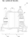
- FIG 1 illustrates an elevation view of an active part of a fluid power equipment 100, that is, a steam turbine, of the state of the art, as mentioned above.
- the steam turbine 100 of the state of the art especially when designed for smaller power ranges, comprises a casing 101 carrying various stages of the turbine there-within in an area 101B of the casing 101, and at a rear end 101A of the fluid power equipment 100, an exhaust casing (not shown) is additionally attached to direct steam flow to a condenser (not shown) for condensing applications or to a customer supply (not shown) for backpressure applications.
- Conventional turbine casings 101 are designed to be of a standard length to avoid design variations which may lead to design delays and increase in manufacturing and fabrication costs.
- Fixed length casings 101 may be optimized based on thermodynamic properties to increase power output and improve performance as demanded by the application. Typically, a fixed length of the turbine casing 101 is determined considering maximum number of stages that are demanded on an average. In cases where the number of stage requirements is less, then there is an extra space indicated in FIG 1 by a distance of Y mm which is about 250 mm for smaller power applications, left in the configured fixed length turbine casing 101 leading to an over-designed equipment.
- the fluid power equipment disclosed in the present invention achieves the aforementioned object, in that the fluid power equipment comprises an exhaust arrangement machineable based on the number of stages to be accommodated in the fluid power equipment.
- the fluid power equipment is a steam turbine with the features of claim 1.
- the steam turbine is an industrial steam turbine and specifically a back-pressure turbine employed in facilities such as oil refineries, petrochemical industry, paper-pulp industry, fibre industry, food industry, etc., where large amounts of steam demand is prevalent.
- the steam turbine includes a plurality of stages and a casing. The stages comprise multiple nozzles and blades. The casing accommodates the stages there-within.
- the casing is configured to have a machineable exhaust arrangement.
- machineable refers to an arrangement permitting removal of a material, for example, cutting of a metal.
- exhaust arrangement refers to a section of a wall of the casing which when machined from the casing, enables exhaust mass produced during operation of the fluid power equipment to flow there-through.
- the exhaust arrangement is configured to have a circular cross section.
- the exhaust arrangement that is, the physical dimensions, are configured based on one or more fluid dynamics parameters associated with a fluid used in the fluid power equipment.
- the fluid dynamics parameters comprise, for example, a pressure of the fluid, a velocity of the fluid, and a volumetric flow of the fluid, etc.
- the casing Upon configuration of the exhaust arrangement, the casing is configured so as to have an area defined by the exhaust arrangement marked on a wall of the casing. This enables the design engineers and other manufacturing personnel to identify the exhaust arrangement.
- the exhaust arrangement is machined based on a number of stages to be accommodated in the fluid power equipment. When the fluid power equipment is being designed for an application requiring up to three stages, then the exhaust arrangement is machined from the casing. Whereas, when the fluid power equipment is being designed for an application requiring more than three stages, then the exhaust arrangement is not machined.
- the casing disclosed herein is configured as a common casing that can accommodate up to five stages of the fluid power equipment without requirement of re-designing of the casing. This is achieved due to the aforementioned exhaust arrangement.
- the exhaust arrangement is configured as a bleed arrangement or an extraction arrangement within the fluid power equipment.
- the fluid power equipment comprises a leakage prevention unit disposable against one of the faces of the casing.
- the leakage prevention unit maintains a direction of flow of exhaust mass generated by the fluid power equipment during operation of the fluid power equipment.
- the leakage prevention unit is configured as a seal, in the shapes comprising, for example, a lid, a plate, a pipe, etc.
- the leakage prevention unit when disposed against the face of the casing, enables maximal flow of exhaust mass of the fluid power equipment via the machined exhaust arrangement. That is, when the fluid power equipment is having less than or equal to three stages, the leakage prevention unit is designed as a sealing plate, so as to direct the exhaust mass flow through the exhaust arrangement.
- the leakage prevention unit is designed as an exhaust pipe, so as to direct the exhaust mass flow through itself into a condenser or to a supply for backpressure applications.
- the exhaust pipe in such cases is, for example, the exhaust casing used in backpressure type steam turbines or condensing type steam turbines.
- one or more physical dimensions of the leakage prevention unit are configured based on a number of stages to be accommodated in the fluid power equipment.
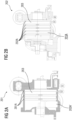
- FIGS 2A-2B illustrate elevation views of steam turbines 201, 202, according to an embodiment of the present invention.
- FIG 2A illustrates a three-stage steam turbine 201.
- Each of the stages 201A of the three-stage steam turbine 201 comprise multiple blades and nozzles (not shown) accommodated within a turbine casing 203.
- FIG 2B illustrates a five-stage steam turbine 202.
- Each of the stages 201A of the five-stage steam turbine 202 are accommodated within the turbine casing 203.
- a common turbine casing 203 can be used to accommodate stages ranging from one to five. This stage accommodation variability using a fixed length turbine casing 203 is possible due to an exhaust arrangement 203A shown in FIG 2A and 2B .
- the exhaust arrangement 203A comprises a portion of the casing configured such that it can be machined, that is, removed if required. After removal of the portion, the machined exhaust arrangement 203A' shown in FIG 2A enables the turbine casing 203 to be used for a three-stage steam turbine 201. Whereas, if there are more than three stages 201A to be accommodated within the turbine casing 203 then the exhaust arrangement 203A is not machined, that is, not removed from the turbine casing 203. Thus, the same turbine casing 203 can be used for up to five stages of a steam turbine.
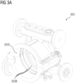
- FIGS 3A-3C illustrate perspective views of turbine casing 203 for the steam turbines 201 and 202 having a machineable exhaust arrangement 203A shown in FIGS 2A-2B , according to an embodiment of the present invention.
- FIG 3A shows the turbine casing 203. Initially, the exhaust arrangement 203A is closed with an inner wall 203C of the turbine casing 203. On the inner wall 203C, multiple grooves 203B are machined, each configured to accommodate a turbine stage 201A therein, shown in FIG 2A .
- FIG 3B shows the turbine casing 203 with a machined exhaust arrangement 203A' as the turbine casing 203 is for a three-stage arrangement.
- a face 203D of the turbine casing 203 is configured so as to be operably coupled with a leakage prevention unit directing the exhaust mass of the steam turbine 201, 202 via the machined exhaust arrangement 203A' only.
- FIG 3C shows the turbine casing 203 having grooves 203B extended in number to accommodate five stages of the steam turbine 201, 202.
- the exhaust arrangement 203A is not machined out from the turbine casing 203 and the face 203D is sealed with help of a standard backpressure or condensing type exhaust casing directing the exhaust mass flow via the exhaust casing.
- FIGS 4A-4C illustrate a leakage prevention unit 401, 402, and 403 disposable against the turbine casing 203 shown in FIGS 3A-3C , according to the present invention.
- FIG 4A shows a leakage prevention unit 401 configured as a circular plate.
- a face 401A of the plate operably couples with the face 203D of the turbine casing 203 shown in FIG 3B to enable the exhaust mass to flow through the machined exhaust arrangement 203A'.
- FIGS 4B and 4C show leakage prevention units 402 and 403 respectively configured such that the faces 402A and 403A operably couple with the face 203D shown in FIG 3C .
- the leakage prevention units 402 and 403 are used for steam turbines having more than three stages, that is, when the exhaust arrangement 203A is not machined from the turbine casing 203. In these cases, the exhaust mass flows through the exhaust pipes 402B and 403B shown respectively in FIGS 4B and 4C .
Landscapes
- Engineering & Computer Science (AREA)
- Mechanical Engineering (AREA)
- General Engineering & Computer Science (AREA)
- Turbine Rotor Nozzle Sealing (AREA)
Description
- The present invention relates to a steam turbine adaptable to a differing number of blade/vane stages. . More particularly the present invention relates to a casing of the steam turbine having a customizable exhaust arrangement to accommodate variations in the quantity of stages of the steam turbine.
-
FIG 1 illustrates an elevation view of an active part of afluid power equipment 100, that is, a steam turbine, of the state of the art, as mentioned above. Thesteam turbine 100 of the state of the art, especially when designed for smaller power ranges, comprises acasing 101 carrying various stages of the turbine there-within in anarea 101B of thecasing 101, and at arear end 101A of thefluid power equipment 100, an exhaust casing (not shown) is additionally attached to direct steam flow to a condenser (not shown) for condensing applications or to a customer supply (not shown) for backpressure applications.Conventional turbine casings 101 are designed to be of a standard length to avoid design variations which may lead to design delays and increase in manufacturing and fabrication costs. Fixedlength casings 101 may be optimized based on thermodynamic properties to increase power output and improve performance as demanded by the application. Typically, a fixed length of theturbine casing 101 is determined considering maximum number of stages that are demanded on an average. In cases where the number of stage requirements is less, then there is an extra space indicated inFIG 1 by a distance of Y mm which is about 250 mm for smaller power applications, left in the configured fixedlength turbine casing 101 leading to an over-designed equipment. - From document
DE 44 25 352 A1 a steam turbine with a casing manufactured in a casting process is known. From documentWO 2008/023046 A1 a steam turbine designed to facilitate modification for operation with power plant incorporating carbon capture facilities is known. From documentDE 197 08 273 C1 a turbine casing is known. From documentUS 2015/252681 A1 modular turbine machine inner and outer casings with multi stage steam extraction sites are known. - Moreover, longer the
turbine casing 101, farther is the bearing centre, indicated in theFIG 1 by a distance of X mm which is about 300mm for smaller power applications. This in turn, requires larger sized rotors thereby posing challenges for rotor-dynamics due to increased flexibility of the rotor. This may lead to an overall increase in the costs and loss of business against competitors. - Therefore, it is an object of the present invention to provide a fluid power equipment of the aforementioned kind, which is cost effective and can be easily configured to accommodate various stage requirements.
- The fluid power equipment disclosed in the present invention achieves the aforementioned object, in that the fluid power equipment comprises an exhaust arrangement machineable based on the number of stages to be accommodated in the fluid power equipment.
- According to the present invention, the fluid power equipment is a steam turbine with the features of claim 1. Advantageously, the steam turbine is an industrial steam turbine and specifically a back-pressure turbine employed in facilities such as oil refineries, petrochemical industry, paper-pulp industry, fibre industry, food industry, etc., where large amounts of steam demand is prevalent. The steam turbine includes a plurality of stages and a casing. The stages comprise multiple nozzles and blades. The casing accommodates the stages there-within.
- The casing is configured to have a machineable exhaust arrangement. As used herein, the term "machineable" refers to an arrangement permitting removal of a material, for example, cutting of a metal. Also used herein, "exhaust arrangement" refers to a section of a wall of the casing which when machined from the casing, enables exhaust mass produced during operation of the fluid power equipment to flow there-through. The exhaust arrangement is configured to have a circular cross section. Advantageously, the exhaust arrangement, that is, the physical dimensions, are configured based on one or more fluid dynamics parameters associated with a fluid used in the fluid power equipment. The fluid dynamics parameters comprise, for example, a pressure of the fluid, a velocity of the fluid, and a volumetric flow of the fluid, etc. Upon configuration of the exhaust arrangement, the casing is configured so as to have an area defined by the exhaust arrangement marked on a wall of the casing. This enables the design engineers and other manufacturing personnel to identify the exhaust arrangement. The exhaust arrangement is machined based on a number of stages to be accommodated in the fluid power equipment. When the fluid power equipment is being designed for an application requiring up to three stages, then the exhaust arrangement is machined from the casing. Whereas, when the fluid power equipment is being designed for an application requiring more than three stages, then the exhaust arrangement is not machined. Thus, advantageously, the casing disclosed herein is configured as a common casing that can accommodate up to five stages of the fluid power equipment without requirement of re-designing of the casing. This is achieved due to the aforementioned exhaust arrangement. According to another embodiment of the present invention, the exhaust arrangement is configured as a bleed arrangement or an extraction arrangement within the fluid power equipment.
- The fluid power equipment comprises a leakage prevention unit disposable against one of the faces of the casing. The leakage prevention unit maintains a direction of flow of exhaust mass generated by the fluid power equipment during operation of the fluid power equipment. The leakage prevention unit is configured as a seal, in the shapes comprising, for example, a lid, a plate, a pipe, etc. The leakage prevention unit, according to one embodiment, when disposed against the face of the casing, enables maximal flow of exhaust mass of the fluid power equipment via the machined exhaust arrangement. That is, when the fluid power equipment is having less than or equal to three stages, the leakage prevention unit is designed as a sealing plate, so as to direct the exhaust mass flow through the exhaust arrangement. Whereas, when the fluid power equipment is having more than three stages, the leakage prevention unit is designed as an exhaust pipe, so as to direct the exhaust mass flow through itself into a condenser or to a supply for backpressure applications. The exhaust pipe in such cases is, for example, the exhaust casing used in backpressure type steam turbines or condensing type steam turbines. Thus, one or more physical dimensions of the leakage prevention unit are configured based on a number of stages to be accommodated in the fluid power equipment.
- The above-mentioned and other features of the invention will now be addressed with reference to the accompanying drawings of the present invention. The illustrated embodiments are intended to illustrate, but not limit the invention.
- The present invention is further described hereinafter with reference to illustrated embodiments shown in the accompanying drawings, in which:
- FIG 1
- illustrates an elevation view of an active part of a steam turbine, of the state of the art.
- FIGS 2A-2B
- illustrate elevation views of steam turbines, according to an embodiment of the present invention.
- FIGS 3A-3C
- illustrate perspective views of turbine casing for the steam turbines shown in
FIGS 2A-2B , having a machineable exhaust arrangement, according to an embodiment of the present invention. - FIGS 4A-4C
- illustrate a leakage prevention unit disposable against the turbine casing shown in
FIGS 3A-3C , according to the present invention. - Various embodiments are described with reference to the drawings, wherein like reference numerals are used to refer to like elements throughout. In the following description, for the purpose of explanation, numerous specific details are set forth in order to provide thorough understanding of one or more embodiments. It may be evident that such embodiments may be practiced without these specific details.
-
FIGS 2A-2B illustrate elevation views ofsteam turbines FIG 2A illustrates a three-stage steam turbine 201. Each of thestages 201A of the three-stage steam turbine 201 comprise multiple blades and nozzles (not shown) accommodated within aturbine casing 203.FIG 2B illustrates a five-stage steam turbine 202. Each of thestages 201A of the five-stage steam turbine 202 are accommodated within theturbine casing 203. As seen inFIGS 2A and 2B , acommon turbine casing 203 can be used to accommodate stages ranging from one to five. This stage accommodation variability using a fixedlength turbine casing 203 is possible due to anexhaust arrangement 203A shown inFIG 2A and 2B . Theexhaust arrangement 203A comprises a portion of the casing configured such that it can be machined, that is, removed if required. After removal of the portion, the machinedexhaust arrangement 203A' shown inFIG 2A enables theturbine casing 203 to be used for a three-stage steam turbine 201. Whereas, if there are more than threestages 201A to be accommodated within theturbine casing 203 then theexhaust arrangement 203A is not machined, that is, not removed from theturbine casing 203. Thus, thesame turbine casing 203 can be used for up to five stages of a steam turbine. -
FIGS 3A-3C illustrate perspective views ofturbine casing 203 for thesteam turbines machineable exhaust arrangement 203A shown inFIGS 2A-2B , according to an embodiment of the present invention.FIG 3A shows theturbine casing 203. Initially, theexhaust arrangement 203A is closed with aninner wall 203C of theturbine casing 203. On theinner wall 203C,multiple grooves 203B are machined, each configured to accommodate aturbine stage 201A therein, shown inFIG 2A .FIG 3B shows theturbine casing 203 with a machinedexhaust arrangement 203A' as theturbine casing 203 is for a three-stage arrangement. In this case, aface 203D of theturbine casing 203 is configured so as to be operably coupled with a leakage prevention unit directing the exhaust mass of thesteam turbine exhaust arrangement 203A' only.FIG 3C shows theturbine casing 203 havinggrooves 203B extended in number to accommodate five stages of thesteam turbine exhaust arrangement 203A is not machined out from theturbine casing 203 and theface 203D is sealed with help of a standard backpressure or condensing type exhaust casing directing the exhaust mass flow via the exhaust casing. -
FIGS 4A-4C illustrate aleakage prevention unit turbine casing 203 shown inFIGS 3A-3C , according to the present invention.FIG 4A shows aleakage prevention unit 401 configured as a circular plate. Aface 401A of the plate operably couples with theface 203D of theturbine casing 203 shown inFIG 3B to enable the exhaust mass to flow through the machinedexhaust arrangement 203A'.FIGS 4B and4C showleakage prevention units faces face 203D shown inFIG 3C . Theleakage prevention units exhaust arrangement 203A is not machined from theturbine casing 203. In these cases, the exhaust mass flows through theexhaust pipes FIGS 4B and4C . -
- 100
- fluid power equipment of state of the art
- 101
- turbine casing of the state of the art
- 101A
- rear end of the fluid power equipment of the state of the art
- 101B
- area of the casing accommodating stages, of the state of the art
- 201, 202
- fluid power equipment (steam turbines having three and five stages respectively)
- 201A, 202A
- stages of the fluid power equipment/steam turbine
- 203
- casing/turbine casing
- 203A
- machineable exhaust arrangement
- 203A'
- machined exhaust arrangement
- 203B
- groove(s)/diaphragm groove accommodating stages there-within
- 203C
- wall of the casing
- 203D
- face of the casing
- 401
- leakage prevention unit for fluid power equipment having less than or equal to 3 stages
- 402, 403
- leakage prevention units/exhaust casings/exhaust pipes for fluid power equipment having more than 3 stages
- 401A
- face of the
leakage prevention unit 401 - 402A
- face of the
leakage prevention unit 402 - 402B
- exhaust pipe of
leakage prevention unit 402 - 403A
- face of the
leakage prevention unit 403 - 403B
- exhaust pipe of
leakage prevention unit 403
Claims (4)
- A steam turbine (201, 202) adaptable to a differing number of blade/vane stages and having:- a plurality of stages (201A, 202A) comprising a plurality of blades and a plurality of nozzles;a casing (203) accommodating the plurality of stages (201A, 202A) there-within and having an open end;characterized in that:if a number of the plurality of stages is larger than 3, the open end of the casing is provided with an exhaust pipe (402B, 403B) configured to direct the exhaust mass flow of the steam turbine into a condenser or to a supply for backpressure applications; andif the number of the plurality of stages is smaller than or equal to 3, the casing is provided with a machined exhaust arrangement (203A') configured as a section of a wall of the casing (203) with removed material not accommodating any of the stages (201A, 202A), and wherein the open end of the casing is provided with a sealing plate (401) configured to direct the exhaust mass flow of the steam turbine through the machined exhaust arrangement (203A') only.
- Steam turbine according to claim 1, wherein the exhaust arrangement (203A') is configured as a bleed arrangement.
- Steam turbine according to claim 1, wherein the exhaust arrangement (203A') is configured as an extraction arrangement.
- Steam turbine (201, 202) according to any one of the claims 1 to 3, wherein a maximum number of stages is 5.
Priority Applications (2)
| Application Number | Priority Date | Filing Date | Title |
|---|---|---|---|
| PL19171955.8T PL3734025T3 (en) | 2019-04-30 | 2019-04-30 | Steam turbine with standardized casing |
| EP19171955.8A EP3734025B1 (en) | 2019-04-30 | 2019-04-30 | Steam turbine with standardized casing |
Applications Claiming Priority (1)
| Application Number | Priority Date | Filing Date | Title |
|---|---|---|---|
| EP19171955.8A EP3734025B1 (en) | 2019-04-30 | 2019-04-30 | Steam turbine with standardized casing |
Publications (2)
| Publication Number | Publication Date |
|---|---|
| EP3734025A1 EP3734025A1 (en) | 2020-11-04 |
| EP3734025B1 true EP3734025B1 (en) | 2025-01-01 |
Family
ID=66349360
Family Applications (1)
| Application Number | Title | Priority Date | Filing Date |
|---|---|---|---|
| EP19171955.8A Active EP3734025B1 (en) | 2019-04-30 | 2019-04-30 | Steam turbine with standardized casing |
Country Status (2)
| Country | Link |
|---|---|
| EP (1) | EP3734025B1 (en) |
| PL (1) | PL3734025T3 (en) |
Family Cites Families (4)
| Publication number | Priority date | Publication date | Assignee | Title |
|---|---|---|---|---|
| DE4425352C2 (en) * | 1994-07-18 | 2001-10-11 | Abb Patent Gmbh | Steam turbine with a turbine housing manufactured in the casting process |
| DE19708273C1 (en) * | 1997-02-28 | 1998-04-30 | Siemens Ag | Industrial steam-turbine housing design |
| GB0616832D0 (en) * | 2006-08-25 | 2006-10-04 | Alstom Technology Ltd | Turbomachine |
| US20150252681A1 (en) * | 2014-03-05 | 2015-09-10 | General Electric Company | Modular turbomachine inner and outer casings with multi-stage steam extraction sites |
-
2019
- 2019-04-30 PL PL19171955.8T patent/PL3734025T3/en unknown
- 2019-04-30 EP EP19171955.8A patent/EP3734025B1/en active Active
Also Published As
| Publication number | Publication date |
|---|---|
| PL3734025T3 (en) | 2025-06-09 |
| EP3734025A1 (en) | 2020-11-04 |
Similar Documents
| Publication | Publication Date | Title |
|---|---|---|
| EP1890059B1 (en) | Compliant plate seals for turbomachinery | |
| EP2540987A1 (en) | Turbine | |
| JP7199160B2 (en) | Adaptive opening cooling path | |
| EP3034818B1 (en) | Steam turbine stationary blade, corresponding steam turbine and modifying method | |
| CN102449268A (en) | turbine | |
| US20170241427A1 (en) | Seal mechanism and rotating machine | |
| EP3039249B1 (en) | Mateface surfaces having a geometry on turbomachinery hardware | |
| CN1092746C (en) | Steam turbine | |
| JP6705742B2 (en) | Compressor having heat shield and operating method | |
| EP3470632A1 (en) | Seal interface with a deflection control feature | |
| EP2759678A1 (en) | Turbine | |
| WO2006046969A8 (en) | Turbine case reinforcement in a gas turbine jet engine | |
| US7118346B2 (en) | Compressor blade | |
| JPS59138701A (en) | Honeycomb labilinth seal | |
| ITMI20071100A1 (en) | ANCHORAGE SYSTEM FOR THE IMPELLERS OF A ROTARY FLUID MACHINE | |
| WO2006065445B1 (en) | Dual pressure euler steam turbine | |
| US20170130737A1 (en) | Rotary machine | |
| US7425114B2 (en) | Shaft seal for a transmission expander or compressor, and transmission expander or compressor having a shaft seal | |
| EP3734025A1 (en) | Steam turbine with standardized casing | |
| US20140271296A1 (en) | No Corner Seal Rotary Vane Actuator | |
| CN102650222B (en) | Turbine shroud and the method for the manufacture of turbine shroud | |
| EP3259480B1 (en) | Internally-cooled compressor diaphragm | |
| US11732720B2 (en) | Turbomachine inner housing | |
| EP1312840A2 (en) | Brush seal element | |
| EP2985426B1 (en) | Blade device for a turbine and corresponding manufacturing method |
Legal Events
| Date | Code | Title | Description |
|---|---|---|---|
| PUAI | Public reference made under article 153(3) epc to a published international application that has entered the european phase |
Free format text: ORIGINAL CODE: 0009012 |
|
| STAA | Information on the status of an ep patent application or granted ep patent |
Free format text: STATUS: THE APPLICATION HAS BEEN PUBLISHED |
|
| AK | Designated contracting states |
Kind code of ref document: A1 Designated state(s): AL AT BE BG CH CY CZ DE DK EE ES FI FR GB GR HR HU IE IS IT LI LT LU LV MC MK MT NL NO PL PT RO RS SE SI SK SM TR |
|
| AX | Request for extension of the european patent |
Extension state: BA ME |
|
| RAP1 | Party data changed (applicant data changed or rights of an application transferred) |
Owner name: SIEMENS ENERGY GLOBAL GMBH & CO. KG |
|
| STAA | Information on the status of an ep patent application or granted ep patent |
Free format text: STATUS: REQUEST FOR EXAMINATION WAS MADE |
|
| 17P | Request for examination filed |
Effective date: 20210430 |
|
| RBV | Designated contracting states (corrected) |
Designated state(s): AL AT BE BG CH CY CZ DE DK EE ES FI FR GB GR HR HU IE IS IT LI LT LU LV MC MK MT NL NO PL PT RO RS SE SI SK SM TR |
|
| STAA | Information on the status of an ep patent application or granted ep patent |
Free format text: STATUS: EXAMINATION IS IN PROGRESS |
|
| 17Q | First examination report despatched |
Effective date: 20220826 |
|
| GRAP | Despatch of communication of intention to grant a patent |
Free format text: ORIGINAL CODE: EPIDOSNIGR1 |
|
| STAA | Information on the status of an ep patent application or granted ep patent |
Free format text: STATUS: GRANT OF PATENT IS INTENDED |
|
| INTG | Intention to grant announced |
Effective date: 20240812 |
|
| GRAS | Grant fee paid |
Free format text: ORIGINAL CODE: EPIDOSNIGR3 |
|
| GRAA | (expected) grant |
Free format text: ORIGINAL CODE: 0009210 |
|
| STAA | Information on the status of an ep patent application or granted ep patent |
Free format text: STATUS: THE PATENT HAS BEEN GRANTED |
|
| AK | Designated contracting states |
Kind code of ref document: B1 Designated state(s): AL AT BE BG CH CY CZ DE DK EE ES FI FR GB GR HR HU IE IS IT LI LT LU LV MC MK MT NL NO PL PT RO RS SE SI SK SM TR |
|
| REG | Reference to a national code |
Ref country code: GB Ref legal event code: FG4D |
|
| REG | Reference to a national code |
Ref country code: DE Ref legal event code: R096 Ref document number: 602019064152 Country of ref document: DE |
|
| REG | Reference to a national code |
Ref country code: CH Ref legal event code: EP |
|
| REG | Reference to a national code |
Ref country code: IE Ref legal event code: FG4D |
|
| REG | Reference to a national code |
Ref country code: LT Ref legal event code: MG9D |
|
| REG | Reference to a national code |
Ref country code: NL Ref legal event code: MP Effective date: 20250101 |
|
| REG | Reference to a national code |
Ref country code: AT Ref legal event code: MK05 Ref document number: 1756435 Country of ref document: AT Kind code of ref document: T Effective date: 20250101 |
|
| PG25 | Lapsed in a contracting state [announced via postgrant information from national office to epo] |
Ref country code: NL Free format text: LAPSE BECAUSE OF FAILURE TO SUBMIT A TRANSLATION OF THE DESCRIPTION OR TO PAY THE FEE WITHIN THE PRESCRIBED TIME-LIMIT Effective date: 20250101 |
|
| PG25 | Lapsed in a contracting state [announced via postgrant information from national office to epo] |
Ref country code: FI Free format text: LAPSE BECAUSE OF FAILURE TO SUBMIT A TRANSLATION OF THE DESCRIPTION OR TO PAY THE FEE WITHIN THE PRESCRIBED TIME-LIMIT Effective date: 20250101 |
|
| PGFP | Annual fee paid to national office [announced via postgrant information from national office to epo] |
Ref country code: PL Payment date: 20250407 Year of fee payment: 7 Ref country code: DE Payment date: 20250428 Year of fee payment: 7 |
|
| PG25 | Lapsed in a contracting state [announced via postgrant information from national office to epo] |
Ref country code: ES Free format text: LAPSE BECAUSE OF FAILURE TO SUBMIT A TRANSLATION OF THE DESCRIPTION OR TO PAY THE FEE WITHIN THE PRESCRIBED TIME-LIMIT Effective date: 20250101 |
|
| PG25 | Lapsed in a contracting state [announced via postgrant information from national office to epo] |
Ref country code: NO Free format text: LAPSE BECAUSE OF FAILURE TO SUBMIT A TRANSLATION OF THE DESCRIPTION OR TO PAY THE FEE WITHIN THE PRESCRIBED TIME-LIMIT Effective date: 20250401 Ref country code: IS Free format text: LAPSE BECAUSE OF FAILURE TO SUBMIT A TRANSLATION OF THE DESCRIPTION OR TO PAY THE FEE WITHIN THE PRESCRIBED TIME-LIMIT Effective date: 20250501 |
|
| PGFP | Annual fee paid to national office [announced via postgrant information from national office to epo] |
Ref country code: IT Payment date: 20250422 Year of fee payment: 7 |
|
| PG25 | Lapsed in a contracting state [announced via postgrant information from national office to epo] |
Ref country code: HR Free format text: LAPSE BECAUSE OF FAILURE TO SUBMIT A TRANSLATION OF THE DESCRIPTION OR TO PAY THE FEE WITHIN THE PRESCRIBED TIME-LIMIT Effective date: 20250101 |
|
| PG25 | Lapsed in a contracting state [announced via postgrant information from national office to epo] |
Ref country code: PT Free format text: LAPSE BECAUSE OF FAILURE TO SUBMIT A TRANSLATION OF THE DESCRIPTION OR TO PAY THE FEE WITHIN THE PRESCRIBED TIME-LIMIT Effective date: 20250502 Ref country code: LV Free format text: LAPSE BECAUSE OF FAILURE TO SUBMIT A TRANSLATION OF THE DESCRIPTION OR TO PAY THE FEE WITHIN THE PRESCRIBED TIME-LIMIT Effective date: 20250101 |
|
| PGFP | Annual fee paid to national office [announced via postgrant information from national office to epo] |
Ref country code: FR Payment date: 20250424 Year of fee payment: 7 |
|
| PG25 | Lapsed in a contracting state [announced via postgrant information from national office to epo] |
Ref country code: BG Free format text: LAPSE BECAUSE OF FAILURE TO SUBMIT A TRANSLATION OF THE DESCRIPTION OR TO PAY THE FEE WITHIN THE PRESCRIBED TIME-LIMIT Effective date: 20250101 Ref country code: GR Free format text: LAPSE BECAUSE OF FAILURE TO SUBMIT A TRANSLATION OF THE DESCRIPTION OR TO PAY THE FEE WITHIN THE PRESCRIBED TIME-LIMIT Effective date: 20250402 |
|
| PG25 | Lapsed in a contracting state [announced via postgrant information from national office to epo] |
Ref country code: AT Free format text: LAPSE BECAUSE OF FAILURE TO SUBMIT A TRANSLATION OF THE DESCRIPTION OR TO PAY THE FEE WITHIN THE PRESCRIBED TIME-LIMIT Effective date: 20250101 |
|
| PGFP | Annual fee paid to national office [announced via postgrant information from national office to epo] |
Ref country code: CZ Payment date: 20250414 Year of fee payment: 7 |
|
| PG25 | Lapsed in a contracting state [announced via postgrant information from national office to epo] |
Ref country code: SE Free format text: LAPSE BECAUSE OF FAILURE TO SUBMIT A TRANSLATION OF THE DESCRIPTION OR TO PAY THE FEE WITHIN THE PRESCRIBED TIME-LIMIT Effective date: 20250101 |
|
| REG | Reference to a national code |
Ref country code: DE Ref legal event code: R097 Ref document number: 602019064152 Country of ref document: DE |
|
| PG25 | Lapsed in a contracting state [announced via postgrant information from national office to epo] |
Ref country code: SM Free format text: LAPSE BECAUSE OF FAILURE TO SUBMIT A TRANSLATION OF THE DESCRIPTION OR TO PAY THE FEE WITHIN THE PRESCRIBED TIME-LIMIT Effective date: 20250101 |
|
| PG25 | Lapsed in a contracting state [announced via postgrant information from national office to epo] |
Ref country code: DK Free format text: LAPSE BECAUSE OF FAILURE TO SUBMIT A TRANSLATION OF THE DESCRIPTION OR TO PAY THE FEE WITHIN THE PRESCRIBED TIME-LIMIT Effective date: 20250101 |
|
| PG25 | Lapsed in a contracting state [announced via postgrant information from national office to epo] |
Ref country code: EE Free format text: LAPSE BECAUSE OF FAILURE TO SUBMIT A TRANSLATION OF THE DESCRIPTION OR TO PAY THE FEE WITHIN THE PRESCRIBED TIME-LIMIT Effective date: 20250101 |
|
| PG25 | Lapsed in a contracting state [announced via postgrant information from national office to epo] |
Ref country code: RO Free format text: LAPSE BECAUSE OF FAILURE TO SUBMIT A TRANSLATION OF THE DESCRIPTION OR TO PAY THE FEE WITHIN THE PRESCRIBED TIME-LIMIT Effective date: 20250101 |
|
| PG25 | Lapsed in a contracting state [announced via postgrant information from national office to epo] |
Ref country code: SK Free format text: LAPSE BECAUSE OF FAILURE TO SUBMIT A TRANSLATION OF THE DESCRIPTION OR TO PAY THE FEE WITHIN THE PRESCRIBED TIME-LIMIT Effective date: 20250101 |
|
| PLBE | No opposition filed within time limit |
Free format text: ORIGINAL CODE: 0009261 |
|
| STAA | Information on the status of an ep patent application or granted ep patent |
Free format text: STATUS: NO OPPOSITION FILED WITHIN TIME LIMIT |
|
| REG | Reference to a national code |
Ref country code: CH Ref legal event code: L10 Free format text: ST27 STATUS EVENT CODE: U-0-0-L10-L00 (AS PROVIDED BY THE NATIONAL OFFICE) Effective date: 20251112 |
|
| REG | Reference to a national code |
Ref country code: CH Ref legal event code: H13 Free format text: ST27 STATUS EVENT CODE: U-0-0-H10-H13 (AS PROVIDED BY THE NATIONAL OFFICE) Effective date: 20251125 |
|
| 26N | No opposition filed |
Effective date: 20251002 |
|
| PG25 | Lapsed in a contracting state [announced via postgrant information from national office to epo] |
Ref country code: LU Free format text: LAPSE BECAUSE OF NON-PAYMENT OF DUE FEES Effective date: 20250430 |
|
| PG25 | Lapsed in a contracting state [announced via postgrant information from national office to epo] |
Ref country code: MC Free format text: LAPSE BECAUSE OF FAILURE TO SUBMIT A TRANSLATION OF THE DESCRIPTION OR TO PAY THE FEE WITHIN THE PRESCRIBED TIME-LIMIT Effective date: 20250101 |
|
| GBPC | Gb: european patent ceased through non-payment of renewal fee |
Effective date: 20250430 |
|
| REG | Reference to a national code |
Ref country code: BE Ref legal event code: MM Effective date: 20250430 |
|
| PG25 | Lapsed in a contracting state [announced via postgrant information from national office to epo] |
Ref country code: GB Free format text: LAPSE BECAUSE OF NON-PAYMENT OF DUE FEES Effective date: 20250430 |
|
| PG25 | Lapsed in a contracting state [announced via postgrant information from national office to epo] |
Ref country code: BE Free format text: LAPSE BECAUSE OF NON-PAYMENT OF DUE FEES Effective date: 20250430 |
|
| PG25 | Lapsed in a contracting state [announced via postgrant information from national office to epo] |
Ref country code: CH Free format text: LAPSE BECAUSE OF NON-PAYMENT OF DUE FEES Effective date: 20250430 |
|
| PG25 | Lapsed in a contracting state [announced via postgrant information from national office to epo] |
Ref country code: IE Free format text: LAPSE BECAUSE OF NON-PAYMENT OF DUE FEES Effective date: 20250430 |