EP3733997A1 - Dispositif de toit amovible - Google Patents
Dispositif de toit amovible Download PDFInfo
- Publication number
- EP3733997A1 EP3733997A1 EP19305552.2A EP19305552A EP3733997A1 EP 3733997 A1 EP3733997 A1 EP 3733997A1 EP 19305552 A EP19305552 A EP 19305552A EP 3733997 A1 EP3733997 A1 EP 3733997A1
- Authority
- EP
- European Patent Office
- Prior art keywords
- carriage
- roof device
- removable roof
- shrouds
- awning
- Prior art date
- Legal status (The legal status is an assumption and is not a legal conclusion. Google has not performed a legal analysis and makes no representation as to the accuracy of the status listed.)
- Granted
Links
- 238000011144 upstream manufacturing Methods 0.000 claims description 26
- 238000013016 damping Methods 0.000 claims description 3
- 239000000725 suspension Substances 0.000 claims 1
- 238000004873 anchoring Methods 0.000 description 7
- 230000005540 biological transmission Effects 0.000 description 3
- 239000002131 composite material Substances 0.000 description 2
- 238000006073 displacement reaction Methods 0.000 description 2
- 230000009182 swimming Effects 0.000 description 2
- 241001503987 Clematis vitalba Species 0.000 description 1
- 238000009825 accumulation Methods 0.000 description 1
- 230000000295 complement effect Effects 0.000 description 1
- 230000000694 effects Effects 0.000 description 1
- 239000004744 fabric Substances 0.000 description 1
- 238000009434 installation Methods 0.000 description 1
- 239000002184 metal Substances 0.000 description 1
- 238000000034 method Methods 0.000 description 1
- 238000012986 modification Methods 0.000 description 1
- 230000004048 modification Effects 0.000 description 1
- 230000002093 peripheral effect Effects 0.000 description 1
- 230000002787 reinforcement Effects 0.000 description 1
- 230000003014 reinforcing effect Effects 0.000 description 1
- 230000000284 resting effect Effects 0.000 description 1
- 230000000717 retained effect Effects 0.000 description 1
- 238000007789 sealing Methods 0.000 description 1
- 238000004804 winding Methods 0.000 description 1
Images


Classifications
-
- E—FIXED CONSTRUCTIONS
- E04—BUILDING
- E04H—BUILDINGS OR LIKE STRUCTURES FOR PARTICULAR PURPOSES; SWIMMING OR SPLASH BATHS OR POOLS; MASTS; FENCING; TENTS OR CANOPIES, IN GENERAL
- E04H15/00—Tents or canopies, in general
- E04H15/02—Tents combined or specially associated with other devices
- E04H15/04—Tents combined or specially associated with other devices suspended type, e.g. from trees or from cantilever supports
-
- E—FIXED CONSTRUCTIONS
- E04—BUILDING
- E04B—GENERAL BUILDING CONSTRUCTIONS; WALLS, e.g. PARTITIONS; ROOFS; FLOORS; CEILINGS; INSULATION OR OTHER PROTECTION OF BUILDINGS
- E04B7/00—Roofs; Roof construction with regard to insulation
- E04B7/14—Suspended roofs
-
- E—FIXED CONSTRUCTIONS
- E04—BUILDING
- E04B—GENERAL BUILDING CONSTRUCTIONS; WALLS, e.g. PARTITIONS; ROOFS; FLOORS; CEILINGS; INSULATION OR OTHER PROTECTION OF BUILDINGS
- E04B7/00—Roofs; Roof construction with regard to insulation
- E04B7/16—Roof structures with movable roof parts
-
- E—FIXED CONSTRUCTIONS
- E04—BUILDING
- E04H—BUILDINGS OR LIKE STRUCTURES FOR PARTICULAR PURPOSES; SWIMMING OR SPLASH BATHS OR POOLS; MASTS; FENCING; TENTS OR CANOPIES, IN GENERAL
- E04H3/00—Buildings or groups of buildings for public or similar purposes; Institutions, e.g. infirmaries or prisons
- E04H3/10—Buildings or groups of buildings for public or similar purposes; Institutions, e.g. infirmaries or prisons for meetings, entertainments, or sports
- E04H3/14—Gymnasiums; Other sporting buildings
Definitions
- the invention relates to a removable roof device of the type comprising a bundle of shrouds, a set of carriages moving along the shrouds and a flexible awning connected to the set of carriages.
- a flexible awning has long been known to cover all or part of a building having an open-air portion on demand.
- a building is for example an outdoor swimming pool or a stadium or an arena or else an open-air amphitheater.
- the devices used for this purpose generally include ropes or cables stretched over the surface of the building to be covered and on which trolleys run, causing in a movement of deployment or folding back the flexible awning suspended from these trolleys.
- Such a device is described in the document FR 1,550,412 .
- the device described in this document comprises a set of self-propelled trolleys which comprise an arrangement of three grooved pulleys, a lower pulley and two upper pulleys, enclosing the cable along which the The self-propelled carriage in question runs so that the cable forms a loop around the lower pulley which is then motorized.
- This method of driving a cable by friction in a pulley groove does not make it possible to obtain high tensile forces. If this is sufficient to move a canopy of a few hundred square meters covering a building such as the basin of a municipal swimming pool, it becomes insufficient to move a velum of several thousand square meters intended to cover a stadium, such as an Olympic stadium by example.
- An object of the invention is to provide a removable roof device which makes it possible to move a very large awning.
- a removable roof device comprising a bundle of shrouds, each of the shrouds extending between a top anchor point and a bottom anchor point of a structure to be covered.
- a mobile awning between a deployed configuration, where the awning covers the structure to be covered, and a collapsed configuration, where the structure to be covered is uncovered, and a set of trolleys on which the awning is hung, arranged so as to move the along the shrouds of the bundle of shrouds between the top and bottom anchor points in order to pass the awning between its extended and retracted configurations and comprising for each of the shrouds of the set of shrouds at least one motorized trolley, at least one trolley motorized cooperating with the associated shroud by meshing or by alternating wedging.
- the removable roof device according to the invention comprises a bundle of shrouds 10.
- Each of the shrouds 10 extends between a so-called high anchor point 2 and a so-called low anchor point 3.
- the top anchor point 2 is here common to all of the shrouds 10 of the bundle of shrouds and overhangs the structure to be covered (not shown).
- the top anchor point 2 is located at the level of a top of a mast or of a pylon.
- the low anchor point 3 is positioned on a periphery of the structure to be covered: there are therefore at least as many stay cables 10 making up the bundle of shrouds as there are low anchor points 3.
- the removable roof device comprises a canopy 1 movable between an extended configuration, where the canopy covers the structure to be covered, and a folded configuration, where the structure to be covered is uncovered.
- the velum 1 is suspended from the bundle of shrouds 10 via a set of carriages 20 which are mounted to move along the shrouds 10 so as to be able to move along the shrouds 10 between the high anchoring points 2 and a positioning point on the stay 10 considered vis-à-vis the awning 1 located between the top 3 and bottom 3 points of the stay 10 considered.
- Connection means 30 are provided between the awning 1 and the carriages 20.
- the removable roof device for each of the shrouds 10 of the bundle of shrouds, the removable roof device according to the invention comprises at least one carriage 20 which is motorized.
- a first embodiment of this motorized carriage 20 will now be described in relation to the figures 2 to 5 . It is associated with a first embodiment of the removable roof device according to the invention.
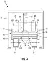
- the stay cable 10 comprises a core 12 which is, here, a flat cable of rectangular section extending between the top 2 and bottom 3 anchor points. edges of the core 12, the shroud 20 comprises a flange 16 extending on either side of the core 12. On an upper face of the core 12, the shroud 10 comprises means 13 forming a circulation path , here two in number, separated by a rack 11 in a central position on the upper face of the core 12. At the level of a lower face of the core 12, the stay cable 10 comprises feed feeders 15 for the carriages 20 motor vehicles which are intended to move along the shroud 10. These feeders 15 are for example conductive cables retained and protected by protection means 14 fixed in a central position and running along the underside of the core 12.
- the stay cable 10 comprises second means ns forming a circulation path, here arranged directly on the underside of the core 12.
- the core 12 is made of a pultruded composite material.
- the rack 11 as well as the means 13 forming the circulation path and the flanges 16 are made of composite materials
- the stay cable 10 further comprises a carrying cable 101 fixed using hoops 102, here on the protection means 14.
- the carrier cable 101 supports all the other elements of the stay cable 10.
- the motorized carriage 20 comprises a housing 21 on which is mounted a drive motor 221.
- the drive motor 221 rotates a motor shaft 220 via means of transmission 222.
- the transmission means 222 comprise for example a chain or a transmission belt.
- a toothed drive wheel 22 is attached to the motor shaft 220. This toothed drive wheel 22 is intended, when using the motorized carriage 20, to cooperate with the rack 13 of the associated stay 10.
- the motorized carriage 20 comprises first rollers 23 mounted on rotation axes 230 fixed to the housing 21 via bearings 231.
- the first rollers 23 are intended, during use of the motorized carriage 20, to cooperate with the first means 13 forming the circulation path of the associated stay cable 10.
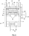
- the first rollers 23 are associated in pairs for the same axis of rotation 230 and are positioned, according to the figures 3 , 4 and 5 , on either side of the toothed drive wheel 22.
- the motorized carriage 20 comprises two pairs of first rollers 23: a pair upstream of the toothed drive wheel 22 and a pair downstream of the toothed drive wheel 22.
- the motorized carriage 20 comprises four pairs of first rollers 23: two pairs upstream and two pairs downstream of the toothed drive wheel 22.
- the main role of the first rollers 23 is to support the entire weight of the carriage 20 thus than the forces transmitted by the connecting means 30 of the velum 1.
- the motorized carriage 20 further comprises second rollers 24 mounted on rotation axes 240 fixed to the housing 21 via bearings 241.
- the second rollers 24 are intended, during use of the motorized carriage 20, to cooperate with the second means forming a circulation path located on the underside of the core 12 of the associated stay cable 10.
- the second rollers 24 are associated in pairs for the same axis of rotation 240 and are positioned, according to the figures 3 , 4 and 5 , on either side of the toothed drive wheel 22.
- the motorized carriage 20 comprises two pairs of second rollers 24: a pair upstream of the toothed drive wheel 22 and a pair downstream of the toothed drive wheel 22, each of the pairs of second rollers 254 being substantially in line with the pairs of first rollers 23.
- the motorized carriage 20 comprises contact means 242 shown diagrammatically on the figure 2 by an arrow.
- these contact means can be one or more contact springs or one or more contact jacks. The use of jacks is to be preferred because it is then possible to achieve safety braking of the motorized carriage 20.
- These contact means 242 are for example interposed between the axis of rotation 240 of the rollers and the casing 21.
- the second rollers 24 are support rollers making it possible to secure the movement of the carriage 20 on the associated stay cable 10, for example preventing a derailment.
- connection means 30 between the carriage 20 and the awning 1 of the removable roof device according to the invention We will now describe in more detail the connection means 30 between the carriage 20 and the awning 1 of the removable roof device according to the invention.
- connection means comprise a tension winch 40 winding / unwinding a hanger cable 33 as needed.
- the tension winch 40 is housed in the housing 21 of the carriage 20.
- the tension winch 40 is fixed to the axes of rotation 230 of the first rollers 23 using a system of bars or connecting rods 211.
- the tension winch 40 is fixed to the casing 21 of the carriage 20. This tension winch 40 will make it possible to adjust the intrinsic tension of the awning 1 in the deployed configuration.
- connection means 30 with caps comprise a bowl 4 fixed to the awning 1.
- This bowl 4 is rigid and serves as an anchoring point of the awning to the connection with the carriage 20: there is therefore as much bowls 4 distributed over the whole of the awning 1 as well as carriages 20 moving on the bundle of shrouds 10 of the removable roof device according to the invention.
- a free end 32 of the hanger cable 33 is fixed directly to the bowl 4.
- the connection means 30 comprise a damper and / or anti-oscillation system 31 which is interposed between the free end 32 of the hanger cable 33 and the bowl 4.
- the damper and / or anti-oscillation system 33 makes it possible to attenuate the risks of the velum 1 flapping, once in the deployed configuration. Indeed, under the effect of gusts of wind, the bowls 4 located in a central zone of the deployed awning 1 can have more or less rapid upward and downward movements with amplitudes which can reach two meters.
- connection means comprise a second tension adjustment winch 41 located and fixed in the bowl 4.
- This second tension adjustment winch 41 complements the tension winch 40 previously described or as a replacement. of it.
- the hanger cable 33 is directly attached to the housing 21 or to the system of connecting rods 211.
- the removable roof device comprises a device for reinforcing the support of the awning in the event of heavy loads on the latter in the deployed configuration. These heavy loads may be due, in winter, to the accumulation of snow on the awning 1 stretched out in the deployed configuration.
- the reinforcement device comprises a set of secondary supporting cables 5 fixed by means of rods 51, 52 to the bowl 4 of the velum 1.
- the rods 51, 52 are articulated 53 to each other and are here positioned on the damping system. and / or anti-oscillation 33.
- the secondary supporting cables 5 are chained together via the rods 51, 52 so as to extend in parallel with the stays 10 between the top 2 and bottom 3 anchor points.
- the installation of the supporting secondary cables 5 is carried out according to the expected weather conditions around the structure to be covered equipped with the removable roof device according to the invention: in particular before the winter season and the secondary cables remain in place until first folding of the velum 1 following the said winter season.
- These secondary cables are only stressed in the event of exceeding a normal capacity of the lines 30 (with the torque limiting device), exceeding due to a snow load, for example.
- the latter comprises a box 6 continuous on the periphery of the structure S.
- the box 6 is fixedly mounted on an upper surface of the periphery of the structure S.
- a fixing of the box 6 on the upper surface of the periphery of the structure S has special anchors , of elastic and / or viscoelastic type, making it possible to take account of a resumption of forces applied by the awning 1 in the deployed position while ensuring freedom of expansion movements while respecting the existing structure S.
- the box 6 supports, movable in translation, the bottom anchoring point 3.
- the bottom anchoring point 3 is connected to a tensioning device comprising a fixed stop 64 and a displacement means 61 (such as a jack) allowing to vary the tension of the stay cable 10 considered, according to the different configurations of the removable roof device according to the invention.
- a removable fixing means 62 of the awning 21 is integral with the box 6. Via an end carriage 20b, an associated canvas point 63 of the awning 1 is introduced and guided in the removable fixing means 62 and a key 631 (like a piston key) locks a connection between the removable fixing means 62 and the canvas point 63, the velum 1 then being in the deployed position. The tensioning of the velum 1 can then be carried out.
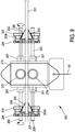
- the removable roof device according to the invention comprises a bundle of shrouds 101 which here are cables carrying circular sections known per se.
- the carriage 200 has a housing 210 in which is mounted so as to rotate freely a first roller 223 (or train of rollers) with a groove coming to bear to roll on the carrying cable 101 of the associated stay cable.
- the carriage 210 comprises a second grooved roller 224, mounted so as to rotate freely in the housing 210.
- This second roller 224 is a support and guide roller which bears to roll under the carrying cable 101 of the associated shroud.
- the role of the second roller 224 is similar to that of the second rollers 24 previously described for the first embodiment of the removable roof device according to the invention.
- the connecting means 30 with the awning 1 are fixed to the casing 210.
- the connecting means 30 for this second embodiment of the removable roof device according to the invention are similar to what had been described previously.
- the carriage 200 comprises means of displacements by alternating wedging which allows the carriage 200 thus motorized to move along the carrying cable 101 forming the associated stay.
- These means of movement by alternating wedging comprise two motorization blocks which are similar.
- the first upstream block is positioned on the side of the carriage which is oriented towards the top anchoring point of the associated stay cable (to the right of the housing 210 on the figure 9 ) and the second downstream block is positioned on the side of the carriage which is oriented towards the bottom anchoring point 3 of the associated stay cable (to the left of the housing 210 on the figure 9 ).
- Each of the upstream and downstream blocks comprises at least one motor 201 which is fixed to the casing 210 of the carriage 210. At the output, the motor 201 drives a threaded rod 202 in rotation which acts as a worm.
- the upstream or downstream block comprises two motors 201 each driving a threaded rod 202 and located on either side of the associated stay.
- Each of the upstream and downstream blocks further comprises a plate 203 possibly associated with a backing plate 203b.
- the plate 203, and possibly the backing plate 203b comprises a threaded through hole in which the threaded rod 202 is screwed / unscrewed.
- the plate 203, and possibly the back plate 203b comprises as many threaded through holes as there are motors 201 of drive / threaded rods 202, here two in number on the figure 9 .
- the plate 203, and possibly the back plate 203b comprises a through opening 206 frustoconical shape through which passes the carrier cable 101 forming the associated stay cable of the carriage 200.
- the orientation of the frustoconical shape of the through opening 206 is such that a small base of the frustoconical shape is on the upstream side (to the right on the figure 9 ) and a large base of the frustoconical shape is on the downstream side (to the left on the figure 9 ).
- the upstream or downstream block further comprises a cover plate 204 which is fixed to and positioned parallel to the plate 203 and which therefore extends at a distance from and opposite the plate 203.
- the cover plate 204 has through holes for the passage. free of the carrying cable 101 forming the stay cable associated with the carriage 200 and of the threaded rod or rods 202.
- the possible backing plate 203b is positioned between the plate 203 and the cover plate 204.
- the frustoconical shape of the set of wedge-wedges 205 is complementary to the shape frustoconical of the through opening 206: thus, once the carriage 200 has been placed on the associated stay, the wedge keys 205 can slide on the supporting cable 101 between a position where they are resting on the cover plate 204, releasing the carrier cable 101, and a position where they come to bear on a frustoconical surface of the through opening 206, consequently clamping the carrier cable 101 by jamming.
- the difference in configuration between the upstream and downstream blocks is in the orientation of the cage.
- the cover plate 204 faces the housing 210 of the carriage 200.
- the plate 203 which is on the side of the housing 210.
- the movement of the carriage 200 takes place in the manner of a rope climber, by alternating wedging between the two downstream and upstream blocks.
- the cage of the downstream block is closest to the casing 210.
- the motors 201 of the downstream block are used to move the cage away from the downstream block of the casing 201 until it is positioned at the end of the threaded rods 202. Therefore, the wedge keys 204 are inserted completely in the through opening 206 thus enclosing the carrier cable 101 by wedging. Consequently, the cage of the downstream block is then blocked on the carrying cable 101 and the casing 210 slides along the carrying cable away from the cage of the downstream block.
- the wedge keys 204 of the upstream block disengage from the through opening 206 of the upstream block and come to bear on the cover plate 204 of the upstream block, which moves them along the carrier cable 101 which they no longer grip.
- the motors 201 of the upstream block are used to move the cage away from the upstream block of the casing 210, until it is positioned at the end of the threaded rods 202.
- the wedge keys 204 of the downstream block disengage from the through opening 206 of the downstream block and come to bear on the cover plate 204 of the downstream block, which moves them along the carrier cable 101 which they no longer grip.
- the motors 201 of the downstream block are used to bring the cage closer to the downstream block of the casing 210, until it is positioned as close as possible to the casing 210 of the carriage 200. Then the cycle begins again.
- the removable roof device according to the invention can also include a sealing device at the periphery of the awning 1 in the deployed position which comprises softer fabric lenses, not participating in the main resistance of the awning 1 but which ensures a closure of the volume of the structure thus covered and therefore a seal in winter for example.
- a sealing device at the periphery of the awning 1 in the deployed position which comprises softer fabric lenses, not participating in the main resistance of the awning 1 but which ensures a closure of the volume of the structure thus covered and therefore a seal in winter for example.
- These skirts positioned in the extension of the awning 1 are fixed, on the one hand all along an edge of the awning 1 between two successive canvas points 63 and come to be closed along the peripheral metal box by means of a zipper type system activated by small dedicated electric trolleys.
Abstract
Description
- L'invention concerne un dispositif de toit amovible du type comportant un faisceau de haubans, un ensemble de chariots se déplaçant le long des haubans et un vélum souple lié à l'ensemble de chariots.
- Il est connu depuis longtemps l'utilisation d'un velum souple pour couvrir à la demande tout ou partie d'un bâtiment présentant une portion à ciel ouvert. Un tel bâtiment est par exemple une piscine extérieure ou un stade ou une arène ou encore un amphithéâtre à ciel ouvert. Les dispositifs utilisés à cette fin comportent généralement des cordes ou des câbles tendus au-dessus de la surface du bâtiment à couvrir et sur lesquels cheminent des chariots entrainant dans un mouvement de déploiement ou reploiement le velum souple suspendu à ces chariots. Un tel dispositif est décrit dans le document
FR 1 550 412 - De manière à faciliter le déploiement ou le reploiement du velum souple, le dispositif décrit dans ce document comporte un ensemble de chariots automoteurs qui comportent une disposition de trois poulies à gorge, une poulie inférieure et deux poulies supérieures, enserrant le câble le long duquel le chariot automoteur considéré chemine de sorte à ce que le câble forme une boucle autour de la poulie inférieure qui est alors motorisée. Ce mode d'entrainement par friction d'un câble dans une gorge de poulie ne permet pas d'obtenir des efforts de traction élevés. Si cela est suffisant pour mouvoir un velum de quelque centaines de mètres carrés couvrant un bâtiment comme le bassin d'une piscine municipale, cela devient insuffisant pour mouvoir un velum de plusieurs milliers de mètres carrés destiné à couvrir un stade, tel un stade olympique par exemple.
- Un but de l'invention est de fournir un dispositif de toit amovible qui permette de mouvoir un velum de très grandes dimensions.
- A cette fin, il est prévu, selon l'invention, un dispositif de toit amovible comportant un faisceau de haubans, chacun des haubans s'étendant entre un point d'ancrage haut et un point d'ancrage bas d'une structure à couvrir, un velum mobile entre une configuration déployée, où le velum couvre la structure à couvrir, et une configuration reployée, où la structure à couvrir est découverte, et un ensemble de chariots sur lesquels est accroché le velum, agencé de sorte à se déplacer le long des haubans du faisceau de haubans entre les points d'ancrages haut et bas afin de faire passer le velum entre ses configurations déployées et reployées et comprenant pour chacun des haubans de l'ensemble de haubans au moins un chariot motorisé, au moins un chariot motorisé coopèrant avec le hauban associé par engrènement ou par coincement alterné.
- Avantageusement, mais facultativement, le dispositif de toit amovible selon l'invention présente au moins l'une des caractéristiques techniques suivantes:
- le hauban comporte des nourrices d'alimentation d'au moins un chariot motorisé associé ;
- le hauban comporte un câble porteur ;
- le velum est accroché à un chariot de l'ensemble de chariots via des moyens de liaisons ;
- les moyens de liaisons comprennent un câble de suspente et un treuil de tension ;
- les moyens de liaisons comportent un système amortisseur ;
- les moyens de liaisons comprennent un système anti-oscillation ;
- les moyens de liaisons comprennent une gamelle fixée sur le vélum ;
- au moins un chariot de l'ensemble de chariots coopère avec le hauban associé par engrènement ;
- le hauban comporte une crémaillère cheminant le long du hauban, le chariot motorisé associé comportant une roue d'entrainement dentée agencée de sorte à coopérer avec la crémaillère pour déplacer le chariot motorisé le long du hauban associé ;
- le hauban comporte des moyens formant chemin de circulation des chariots qui lui sont associés ;
- le chariot comporte des galets agencés de sorte à coopérer avec les moyens formant chemin de circulation ;
- au moins un chariot de l'ensemble de chariots coopère avec le hauban associé par coincement alterné ;
- au moins un chariot comporte des premières mâchoires amonts et des deuxièmes mâchoires avales montées mobiles à translation sur le chariot selon une direction de déplacement du chariot sur le hauban associé, les premières et deuxièmes mâchoires étant agencées de sorte, lors d'un déplacement du chariot sur le hauban associé, à venir serrer par coincement une partie du hauban associé de manière alternative ;
- les mâchoires présentent une forme de coin; et,
- les premières et deuxièmes mâchoires sont entraînées via une liaison hélicoïdale.
- D'autres caractéristiques et avantages de l'invention ressortiront à la lecture de la description qui suit d'un mode de réalisation de l'invention. Aux dessins annexés :
- la
figure 1 est une vue schématique tridimensionnelle d'un dispositif de toit amovible selon l'invention ; - la
figure 2 est une vue schématique de côté d'un premier mode de réalisation d'un chariot automoteur pour le dispositif de toit amovible selon l'invention ; - la
figure 3 est une vue schématique de face du chariot de lafigure 2 ; - la
figure 4 est une vue schématique de face illustrant la coopération du chariot de lafigure 2 avec un hauban du dispositif de toit selon l'invention ; - la
figure 5 est une vue schématique de face illustrant la coopération du chariot de lafigure 2 avec une variante de réalisation du hauban de lafigure 4 ; - la
figure 6 est une vue schématique de côté partielle d'une variante de réalisation du chariot de lafigure 2 ; - la
figure 7 est une vue schématique de côté d'une partie des moyens de liaisons du velum avec un chariot ; - la
figure 8 est une vue schématique de côté d'un point d'ancrage bas pour le dispositif de toit amovible selon l'invention ; et, - la
figure 9 est une vue schématique de côté d'un deuxième mode de réalisation d'un chariot automoteur pour le dispositif de toit selon l'invention. - Pour plus de clarté, les éléments identiques ou similaires sont repérés par des signes de référence identiques sur l'ensemble des figures.
- En référence à la
figure 1 , nous allons décrire un dispositif de toit amovible selon l'invention de manière générale. Le dispositif de toit amovible selon l'invention comporte un faisceau de haubans 10. Chacun des haubans 10 s'étend entre point d'ancrage dit haut 2 et un point d'ancrage dit bas 3. Le point d'ancrage haut 2 est ici commun à l'ensemble des haubans 10 du faisceau de haubans et surplombe la structure à couvrir (non représentée). Par exemple, le point d'ancrage haut 2 est situé au niveau d'un sommet d'un mât ou d'un pylône. Le point d'ancrage bas 3 est positionné sur une périphérie de la structure à couvrir : il y a donc au minimum autant de haubans 10 composant le faisceau de haubans que de points d'ancrages bas 3. L'ensemble des points d'ancrages bas 3 est uniformément répartie sur la périphérie de la structure à couvrir. D'autre part, le dispositif de toit amovible selon l'invention comprend un velum 1 mobile entre une configuration déployée, où le velum couvre la structure à couvrir, et une configuration reployée, où la structure à couvrir est découverte. Le velum 1 est suspendu au faisceau de haubans 10 via un ensemble de chariots 20 qui sont montés mobiles le long des haubans 10 de sorte à pouvoir se déplacer le long des haubans 10 entre les points d'ancrages hauts 2 et un point de positionnement sur le hauban 10 considéré en vis-à-vis du velum 1 situé entre les points haut 3 et bas 3 du hauban 10 considéré. Des moyens de liaisons 30 sont prévus entre le velum 1 et les chariots 20. Ainsi le déplacement des chariots 20 le long des haubans 10 va permettre de faire passer le velum 1 de sa configuration déployée à sa configuration reployée et inversement. Il est à noter que sur lafigure 1 , le velum 1 est représenté de manière partielle et dans sa configuration déployée. - Pour chacun des haubans 10 du faisceau de haubans, le dispositif de toit amovible selon l'invention comprend au moins un chariot 20 qui est motorisé. Un premier mode de réalisation de ce chariot 20 motorisé va maintenant être décrit en relation avec les
figures 2 à 5 . Il est associé à un premier mode de réalisation du dispositif de toit amovible selon l'invention. - Dans ce mode de réalisation du dispositif de toit amovible selon l'invention, le hauban 10 comporte une âme 12 qui est, ici, un câble plat de section rectangulaire s'étendant entre les points d'ancrages haut 2 et bas 3. Sur les chants de l'âme 12, le hauban 20 comprend un rebord 16 s'étendant de part et d'autre de l'âme 12. Sur une face supérieure de l'âme 12, le hauban 10 comporte des moyens 13 formant chemin de circulation, ici au nombre de deux, séparés par une crémaillère 11 en position centrale sur la face supérieure de l'âme 12. Au niveau d'une face inférieure de l'âme 12, le hauban 10 comporte des nourrices d'alimentation 15 des chariots 20 motorisés qui sont destinés à se déplacer le long du hauban 10. Ces nourrices 15 sont par exemple des câbles conducteurs retenus et protégés par des moyens de protection 14 fixés en position centrale et cheminant le long de la face inférieure de l'âme 12. De part et d'autre des moyens de protection 14, le hauban 10 comporte des deuxièmes moyens formant chemin de circulation, ici directement aménagés sur la face inférieure de l'âme 12. Par exemple, au moins l'âme 12 est en un matériau composite pultrudé. La crémaillère 11 ainsi que les moyens 13 formant chemin de circulation et les rebords 16 sont en matériaux composites
- Dans une variante de réalisation illustrée à la
figure 5 , le hauban 10 comporte, en outre, un câble porteur 101 fixé à l'aide d'arceaux 102, ici sur les moyens de protection 14. Ainsi, le câble porteur 101 supporte l'ensemble des autres éléments du hauban 10. - Se déplaçant le long du hauban 10 qui vient d'être décrit, le chariot 20 motorisé comporte un carter 21 sur lequel est monté un moteur d'entrainement 221. Le moteur d'entrainement 221 meut en rotation un axe moteur 220 via des moyens de transmission 222. Les moyens de transmission 222 comprennent par exemple une chaine ou une courroie de transmission. Sur l'axe moteur 220 est montée solidaire une roue d'entrainement dentée 22. Cette roue d'entrainement dentée 22 est destinée, lors d'une utilisation du chariot 20 motorisé, à coopérer avec la crémaillère 13 du hauban 10 associé.
- D'autre part, le chariot 20 motorisé comporte des premiers galets 23 montés sur des axes de rotations 230 fixés au carter 21 via des paliers 231. Les premiers galets 23 sont destinés, lors d'une utilisation du chariot 20 motorisé, à coopérer avec les premiers moyens 13 formant chemin de circulation du hauban 10 associé. Ici, les premiers galets 23 sont associés par paires pour un même axe de rotation 230 et sont positionnés, selon les
figures 3 ,4 et5 , de part et d'autre de la roue d'entrainement dentée 22. Dans une configuration illustrée à lafigure 2 , le chariot 20 motorisé comporte deux paires de premiers galets 23 : une paire en amont de la roue d'entrainement dentée 22 et une paire en aval de la roue d'entrainement dentée 22. Dans une variante, illustrée à lafigure 6 , le chariot 20 motorisé comporte quatre paires de premiers galets 23 : deux paires en amont et deux paires en aval de la roue d'entrainement dentée 22. Le rôle principal des premiers galets 23 est de supporter l'ensemble du poids du chariot 20 ainsi que les efforts transmis par les moyens de liaisons 30 du velum 1. - Le chariot 20 motorisé comprend en outre des deuxièmes galets 24 montés sur des axes de rotations 240 fixés au carter 21 via des paliers 241. Les deuxièmes galets 24 sont destinés, lors d'une utilisation du chariot 20 motorisé, à coopérer avec les deuxièmes moyens formant chemin de circulation situé sur la face inférieure de l'âme 12 du hauban 10 associé. Ici, les deuxièmes galets 24 sont associés par paires pour un même axe de rotation 240 et sont positionnés, selon les
figures 3 ,4 et5 , de part et d'autre de la roue d'entrainement dentée 22. Le chariot 20 motorisé comporte deux paires de deuxièmes galets 24 : une paire en amont de la roue d'entrainement dentée 22 et une paire en aval de la roue d'entrainement dentée 22, chacune des paires de deuxièmes galets 254 étant sensiblement au droit des paires de premiers galets 23. Afin d'assurer un appui des deuxièmes galets 24 sur les deuxièmes moyens formant chemin de circulation, le chariot 20 motorisé comporte des moyens de contact 242 schématisés sur lafigure 2 par une flèche. Par exemple, ces moyens de contact peuvent être un ou plusieurs ressorts de contact ou un ou plusieurs vérins de contact. L'utilisation de vérins est à privilégier car il est alors possible de réaliser un freinage de sécurité du chariot 20 motorisé. Ces moyens de contact 242 sont par exemple interposés entre l'axe de rotation 240 des galets et le carter 21. Les deuxièmes galets 24 sont des galets de support permettant de sécuriser le déplacement du chariot 20 sur le hauban 10 associé, comme par exemple empêcher un déraillement. - Nous allons maintenant décrire plus en détail les moyens de liaisons 30 entre le chariot 20 et le velum 1 du dispositif de toit amovible selon l'invention.
- Au niveau du chariot 20, les moyens de liaisons comprennent un treuil 40 de tension enroulant/déroulant un câble de suspente 33 en fonction des besoins. Le treuil 40 de tension est logé dans le carter 21 du chariot 20. Afin de transmettre directement les efforts aux premiers galets 23, le treuil 40 de tension est fixé sur les axes de rotation 230 des premiers galets 23 à l'aide d'un système de barres ou de bielles 211. Dans une variante de réalisation, le treuil 40 de tension est fixé sur le carter 21 du chariot 20. Ce treuil 40 de tension va permettre de régler la tension intrinsèque du velum 1 en configuration déployée.
- Au niveau du velum 1, les moyens de liaisons 30 avec des chapeaux comprennent une gamelle 4 fixé au velum 1. Cette gamelle 4 est rigide et sert de point d'ancrage du velum à la liaison avec le chariot 20 : il y a donc autant de gamelles 4 réparties sur l'ensemble du velum 1 que de chariots 20 se déplaçant sur le faisceau de haubans 10 du dispositif de toit amovible selon l'invention. Dans une première variante de réalisation, une extrémité libre 32 du câble de suspente 33 est fixée directement sur la gamelle 4. Dans une deuxième variante de réalisation, les moyens de liaisons 30 comprennent un système amortisseur et/ou anti oscillation 31 qui est interposé entre l'extrémité libre 32 du câble de suspente 33 et la gamelle 4. Le système amortisseur et/ou anti-oscillation 33 permet d'atténuer les risques de battement du velum 1, une fois en configuration déployée. En effet, sous l'effet de rafales de vent, les gamelles 4 situées dans une zone centrale du velum 1 déployé peuvent avoir des mouvements ascendants et descendants plus ou moins rapides avec des amplitudes pouvant atteindre deux mètres.
- Selon une variante de réalisation, les moyens de liaisons comportent un deuxième treuil 41 de réglage de la tension situé et fixé dans la gamelle 4. Ce deuxième treuil 41 de réglage de la tension vient en complément du treuil 40 de tension précédemment décrit ou en remplacement de celui-ci. Dans ce dernier cas, le câble de suspente 33 est directement fixé au carter 21 ou au système de bielles 211.
- En référence à la
figure 7 , le dispositif de toit amovible selon l'invention comporte un dispositif de renforcement du support du velum en cas de fortes charges de ce dernier en configuration déployée. Ces fortes charges peuvent être dues, en hiver, par l'accumulation de neige sur le velum 1 tendu en configuration déployée. Pour cela le dispositif de renforcement comporte un ensemble de câbles secondaires porteurs 5 fixés à l'aide de biellettes 51, 52 à la gamelle 4 du velum 1. Les biellettes 51, 52 sont articulées 53 entre elles et sont ici positionnées sur le système amortisseur et/ou anti-oscillation 33. Les câbles secondaires porteurs 5 sont chainés entre eux via les biellettes 51, 52 de sorte à s'étendre en parallèle des haubans 10 entre les points d'ancrages haut 2 et bas 3. En pratique, la mise en place des câbles secondaires porteurs 5 s'effectue en fonction des conditions météo attendues autour de la structure à couvrir équipée du dispositif de toit amovible selon l'invention : en particulier avant la saison hivernale et les câbles secondaires restent en place jusqu'au premier reploiement du velum 1 suivant ladite saison hivernale. Ces câbles secondaires ne sont sollicités qu'en cas de dépassement d'une capacité normale des suspentes 30 (avec le dispositif de limitation de couple), dépassement dû à une charge de neige, par exemple. - Maintenant en référence à la
figure 8 , nous allons décrire plus en détail la structure S à couvrir par le dispositif de toit amovible selon l'invention au niveau d'un point d'ancrage bas 3. Au niveau de la périphérie de la structure S, cette dernière comporte un caisson 6 continu sur la périphérie de la structure S. Le caisson 6 est monté fixe sur une surface supérieure de la périphérie de la structure S. Par exemple, une fixation du caisson 6 sur la surface supérieure de la périphérie de la structure S comporte des ancrages spéciaux, de type élastiques et /ou viscoélastiques, permettant de tenir compte d'une reprise d'efforts appliqués par le velum 1 en position déployée tout en assurant une liberté des mouvements de dilatation tout en respectant la structure S existante. Le caisson 6 supporte, mobile à translation, le point d'ancrage bas 3. Le point d'ancrage bas 3 est relié à un dispositif de mise en tension comprenant une butée fixe 64 et un moyen de déplacement 61 (comme un vérin) permettant de faire varier la tension du hauban 10 considéré, selon les différentes configurations du dispositif de toit amovible selon l'invention. Un moyen de fixation amovible 62 du vélum 21 est solidaire du caisson 6. Par l'intermédiaire d'un chariot d'extrémité 20b, une pointe de toile 63 associée du vélum 1 est introduite et guidée dans le moyen de fixation amovible 62 et une clavette 631 (comme une clavette à piston) vient verrouiller une liaison entre le moyen de fixation amovible 62 et la point de toile 63, le velum 1 étant alors en position déployée. La mise en tension du velum 1 peut alors être réalisée. Un scénario inverse se produit pour le reploiement du velum 1 : après un relâchement des tensions au niveau des différentes gamelles 4, les clavettes 66 sont désengagées de leur pointe de toile 63 associée, qui est alors entrainée vers le haut en éloignement du point d'ancrage bas 3 par le chariot d'extrémité 20b associé. - En référence à la
figure 9 , nous allons décrire un deuxième mode de réalisation d'un dispositif de toit amovible selon l'invention, en particulier d'un chariot 200 motorisé de l'ensemble de chariots du dispositif de toit amovible selon l'invention. - Dans ce deuxième mode de réalisation, le dispositif de toit amovible selon l'invention comporte un faisceau de haubans 101 qui sont ici des câbles porteurs de sections circulaires connus en soi. Le chariot 200 comporte un carter 210 dans lequel est monté libre à rotation un premier galet 223 (ou train de galets) à gorge venant en appui rouler sur le câble porteur 101 du hauban associé. Au droit du premier galet 223, le chariot 210 comporte un deuxième galet 224 à gorge, monté libre à rotation dans le carter 210. Ce deuxième galet 224 est un galet de support et de guidage qui vient en appui rouler sous le câble porteur 101 du hauban associé. Le rôle du deuxième galet 224 est similaire à celui des deuxièmes galets 24 précédemment décrit pour le premier mode de réalisation du dispositif de toit amovible selon l'invention. Comme précédemment les moyens de liaisons 30 avec le velum 1 sont fixés sur le carter 210. Les moyens de liaisons 30 pour ce deuxième mode de réalisation du dispositif de toit amovible selon l'invention sont similaires à ce qui avait été décrit précédemment.
- D'autre part, le chariot 200 comporte des moyens de déplacements par coincement alterné qui permet au chariot 200 ainsi motorisé de se déplacer le long du câble porteur 101 formant le hauban associé. Ces moyens de déplacements par coincement alterné comportent deux blocs de motorisation qui sont semblables. Le premier bloc amont est positionné du côté du chariot qui est orienté vers le point d'ancrage haut du hauban associé (à droite du carter 210 sur la
figure 9 ) et le deuxième bloc aval est positionné du côté du chariot qui est orienté vers le point d'ancrage bas 3 du hauban associé (à gauche du carter 210 sur lafigure 9 ). - Chacun des blocs amont et aval comportent au moins un moteur 201 qui est fixé sur le carter 210 du chariot 210. En sortie le moteur 201 entraine en rotation une tige filetée 202 qui fait office de vis sans fin. Ici, illustré sur la
figure 9 , le bloc amont ou aval comporte deux moteurs 201 entrainement chacun une tige filetée 202 et situés de part et d'autre du hauban associé. Chacun des blocs amont et aval comporte en outre une plaque 203 associée éventuellement à une contre plaque 203b. La plaque 203, et éventuellement la contre plaque 203b comporte un orifice traversant taraudé dans lequel vient se visser/dévisser la tige filetée 202. La plaque 203, et éventuellement la contreplaque 203b, comprend autant d'orifices traversants filetés que de moteurs 201 d'entrainement/tiges filetées 202, ici au nombre de deux sur lafigure 9 . D'autre part, la plaque 203, et éventuellement la contre plaque 203b, comprend une ouverture traversante 206 de forme tronconique à travers laquelle passe le câble porteur 101 formant le hauban associé du chariot 200. L'orientation de la forme tronconique de l'ouverture traversante 206 est telle qu'une petite base de la forme tronconique est côté amont (vers la droite sur lafigure 9 ) et une grande base de la forme tronconique est côté aval (vers la gauche sur lafigure 9 ). Le bloc amont ou aval comporte en outre une plaque capot 204 qui est fixée sur et positionnée parallèlement à la plaque 203 et qui s'étend donc à distance et en regard de la plaque 203. La plaque capot 204 comporte des orifices traversants pour le passage libre du câble porteur 101 formant le hauban associé au chariot 200 et de la ou des tiges filetées 202. L'éventuelle contre plaque 203b est positionnée entre la plaque 203 et la plaque capot 204. Ainsi l'ensemble formé par les plaques 203 et plaques capots 204 délimite une cage dans laquelle est emprisonné une série de clavettes-coins 205 tronconiques orientées de sorte à pouvoir venir s'insérer dans l'ouverture traversante 206. La forme tronconique de l'ensemble de clavettes-coins 205 est complémentaire de la forme tronconique de l'ouverture traversante 206 : ainsi, une fois le chariot 200 mis en place sur le hauban associé, les clavettes-coins 205 peuvent glisser sur le câble porteur 101 entre une position où elles sont en appui sur la plaque capot 204, libérant le câble porteur 101, et une position où elles viennent en appuis sur une surface tronconique de l'ouverture traversante 206, serrant par conséquent le câble porteur 101 par coincement. - La différence de configuration entre les blocs amont et aval est dans l'orientation de la cage. Dans le bloc amont, la plaque capot 204 est face au carter 210 du chariot 200. Dans le bloc aval, c'est la plaque 203 qui est du côté du carter 210.
- En fonctionnement, le déplacement du chariot 200 s'effectue à la manière d'un grimpeur à la corde lisse, par coincement alterné entre les deux blocs aval et amont. Nous allons brièvement décrire une séquence de déplacement du chariot 200 sur le hauban associé. Dans un premier temps, la cage du bloc aval est au plus proche du carter 210. Les moteurs 201 du bloc aval sont mis en oeuvre pour éloigner la cage du bloc aval du carter 201 jusqu'à ce qu'elle soit positionnée en extrémité des tiges filetées 202. Dès lors, les clavettes-coins 204 s'insèrent complètement dans l'ouverture traversante 206 enserrant ainsi le câble porteur 101 par coincement. En conséquence, la cage du bloc aval est alors bloquée sur le câble porteur 101 et le carter 210 coulisse le long du câble porteur en s'éloignant de la cage du bloc aval. Dans le même temps, lors de ce mouvement du carter 210 du chariot 200, les clavettes-coins 204 du bloc amont se désengagent de l'ouverture traversante 206 du bloc amont et viennent en appui sur la plaque capot 204 du bloc amont, ce qui les déplace le long du câble porteur 101 qu'elles n'enserrent plus. Les moteurs 201 du bloc amont sont mis en oeuvre pour éloigner la cage du bloc amont du carter 210, jusqu'à ce qu'elle soit positionnée en extrémité des tiges filetées 202.
- Ensuite, dans un deuxième temps, une fois les cages des blocs amont et aval en extrémité des tiges filetées 202 respectives, le fonctionnement des moteurs 201 du bloc amont est inversé de sorte à rapprocher la cage du bloc amont du carter 210, jusqu'à ce qu'elle soit positionnée au plus près dudit carter 210. Dès lors, les clavettes-coins 204 du bloc amont s'insèrent complètement dans l'ouverture traversante 206 du bloc amont enserrant ainsi le câble porteur 101 par coincement. En conséquence, la cage du bloc amont est alors bloquée sur le câble porteur 101 et le carter 210 coulisse le long du câble porteur en se rapprochant de la cage du bloc amont. Dans le même temps, lors de ce mouvement du carter 210 du chariot 200, les clavettes-coins 204 du bloc aval se désengagent de l'ouverture traversante 206 du bloc aval et viennent en appui sur la plaque capot 204 du bloc aval, ce qui les déplace le long du câble porteur 101 qu'elles n'enserrent plus. Les moteurs 201 du bloc aval sont mis en oeuvre pour rapprocher la cage du bloc aval du carter 210, jusqu'à ce qu'elle soit positionnée en au plus proche du carter 210 du chariot 200. Puis le cycle recommence.
- Avec un dispositif de toit amovible selon l'invention qui vient d'être décrit, il est possible de couvrir un stade olympique comme celui de Montréal au Canada avec un velum 1 de l'ordre de 20000 m2 et un faisceau de dix-sept haubans 10 ou 101 associés avec un ensemble de vingt-cinq à vingt-sept chariots 20, 200 reliés à autant de gamelles 4 ménagées sur le velum 1, ainsi qu'un ensemble de dix-sept chariots d'extrémité 20b. La mise en route des chariots motorisés peut être pilotée de manière manuelle ou automatique ou les deux : pilotage manuel en cas de situations exceptionnelles et pilotage automatique pour les cas d'exploitation normale.
- Au surplus, le dispositif de toit amovible selon l'invention peut comporter également un dispositif de calfeutrement à la périphérie du velum 1 en position déployée qui comprend des lentilles de toile plus souples, ne participant pas à la résistance principale du velum 1 mais qui assure une fermeture du volume de la structure ainsi recouverte et donc un étanchéité en période hivernale par exemple. Ces jupes positionnées dans le prolongement du velum 1 sont fixées, d'une part tout le long d'un bord du velum 1 entre deux pointes de toile 63 successives et viennent se fermer le long du caisson métallique périphérique par l'intermédiaire d'un système type fermeture éclair activé par des petits chariots électriques dédiés.
- Bien entendu, il est possible d'apporter à l'invention de nombreuses modifications sans pour autant sortir du cadre de celle-ci.
Claims (16)
- Dispositif de toit amovible comportant un faisceau de haubans (10), chacun des haubans s'étendant entre un point d'ancrage haut (2) et un point d'ancrage bas (3) d'une structure (S) à couvrir, un velum (1) mobile entre une configuration déployée, où le velum couvre la structure à couvrir, et une configuration reployée, où la structure à couvrir est découverte, et un ensemble de chariots (20,20b;200) sur lesquels est accroché le velum, agencé de sorte à se déplacer le long des haubans du faisceau de haubans entre les points d'ancrages haut et bas afin de faire passer le velum entre ses configurations déployées et reployées et comprenant pour chacun des haubans de l'ensemble de haubans au moins un chariot motorisé, caractérisé en ce qu'au moins un chariot motorisé coopère avec le hauban associé par engrènement ou par coincement alterné.
- Dispositif de toit amovible selon la revendication 1, caractérisé en ce que le hauban comporte des nourrices d'alimentation (15) d'au moins un chariot motorisé associé.
- Dispositif de toit amovible selon la revendication 1 ou 2, caractérisé en ce que le hauban comporte un câble porteur (101).
- Dispositif de toit amovible selon l'une des revendications 1 à 3, caractérisé en ce que le velum est accroché à un chariot de l'ensemble de chariots via des moyens de liaisons (30).
- Dispositif de toit amovible selon la revendication 4, caractérisé en ce que les moyens de liaisons comprennent un câble de suspente (33) et un treuil de tension (40).
- Dispositif de toit amovible selon la revendication 4 ou 5, caractérisé en ce que les moyens de liaisons comportent un système amortisseur (31).
- Dispositif de toit amovible selon l'une des revendications 4 à 6, caractérisé en ce que les moyens de liaisons comprennent un système anti-oscillation (31).
- Dispositif de toit amovible selon l'une des revendications 4 à 7, caractérisé en ce que les moyens de liaisons comprennent une gamelle (4) fixée sur le velum.
- Dispositif de toit amovible selon l'une des revendications 1 à 8, caractérisé en ce qu'au moins un chariot (20) de l'ensemble de chariots coopère avec le hauban associé par engrènement.
- Dispositif de toit amovible selon la revendication 9, caractérisé en ce que le hauban comporte une crémaillère (11) cheminant le long du hauban, le chariot motorisé associé comportant une roue d'entrainement dentée (22) agencée de sorte à coopérer avec la crémaillère pour déplacer le chariot motorisé le long du hauban associé.
- Dispositif de toit amovible selon la revendication 10, caractérisé en ce que le hauban comporte des moyens formant chemin de circulation (13) des chariots qui lui sont associés.
- Dispositif de toit amovible selon la revendication 11, caractérisé en ce que le chariot comporte des galets (23,24) agencés de sorte à coopérer avec les moyens formant chemin de circulation.
- Dispositif de toit amovible selon la revendication 1, caractérisé en ce qu'au moins un chariot (200) de l'ensemble de chariots coopère avec le hauban associé par coincement alterné.
- Dispositif de toit amovible selon la revendication 13, caractérisé en ce qu'au moins un chariot comporte des premières mâchoires (205) amonts et des deuxièmes mâchoires (205) avales montées mobiles à translation sur le chariot selon une direction de déplacement du chariot sur le hauban associé, les premières et deuxièmes mâchoires (205) étant agencées de sorte, lors d'un déplacement du chariot sur le hauban associé, à venir serrer par coincement une partie du hauban associé de manière alternative.
- Dispositif de toit amovible selon la revendication 14, caractérisé en ce que les mâchoires présentent une forme de coin.
- Dispositif de toit amovible selon la revendication 14 ou 15, caractérisé en ce que les premières et deuxièmes mâchoires sont entraînées via une liaison hélicoïdale (202,209,203,203b).
Priority Applications (1)
| Application Number | Priority Date | Filing Date | Title |
|---|---|---|---|
| EP19305552.2A EP3733997B1 (fr) | 2019-04-30 | 2019-04-30 | Dispositif de toit amovible |
Applications Claiming Priority (1)
| Application Number | Priority Date | Filing Date | Title |
|---|---|---|---|
| EP19305552.2A EP3733997B1 (fr) | 2019-04-30 | 2019-04-30 | Dispositif de toit amovible |
Publications (2)
| Publication Number | Publication Date |
|---|---|
| EP3733997A1 true EP3733997A1 (fr) | 2020-11-04 |
| EP3733997B1 EP3733997B1 (fr) | 2021-08-25 |
Family
ID=66625874
Family Applications (1)
| Application Number | Title | Priority Date | Filing Date |
|---|---|---|---|
| EP19305552.2A Active EP3733997B1 (fr) | 2019-04-30 | 2019-04-30 | Dispositif de toit amovible |
Country Status (1)
| Country | Link |
|---|---|
| EP (1) | EP3733997B1 (fr) |
Cited By (1)
| Publication number | Priority date | Publication date | Assignee | Title |
|---|---|---|---|---|
| US11499311B1 (en) | 2021-04-22 | 2022-11-15 | Sophie TAILLIBERT | Removable roof device |
Citations (5)
| Publication number | Priority date | Publication date | Assignee | Title |
|---|---|---|---|---|
| DE1272522B (de) * | 1967-05-16 | 1968-07-11 | Haushahn Fa C | Laengs einer Fuehrung laufender Schleppwagen zum Verziehen von Abdeckplanen |
| FR1550412A (fr) | 1967-11-09 | 1968-12-20 | ||
| DE2316993B1 (de) * | 1973-04-05 | 1974-06-06 | L. Stromeyer & Co Gmbh, 7750 Konstanz | Verfahren zum Herstellen einer Überdachung od.dgl |
| US4802314A (en) * | 1987-11-24 | 1989-02-07 | Schildge Jr Adam T | Cable-stay roof for stadium or arena and method of construction of same |
| AT507675A4 (de) * | 2009-01-16 | 2010-07-15 | Eccon Eng Computer Consult | Befestigungskörper |
-
2019
- 2019-04-30 EP EP19305552.2A patent/EP3733997B1/fr active Active
Patent Citations (5)
| Publication number | Priority date | Publication date | Assignee | Title |
|---|---|---|---|---|
| DE1272522B (de) * | 1967-05-16 | 1968-07-11 | Haushahn Fa C | Laengs einer Fuehrung laufender Schleppwagen zum Verziehen von Abdeckplanen |
| FR1550412A (fr) | 1967-11-09 | 1968-12-20 | ||
| DE2316993B1 (de) * | 1973-04-05 | 1974-06-06 | L. Stromeyer & Co Gmbh, 7750 Konstanz | Verfahren zum Herstellen einer Überdachung od.dgl |
| US4802314A (en) * | 1987-11-24 | 1989-02-07 | Schildge Jr Adam T | Cable-stay roof for stadium or arena and method of construction of same |
| AT507675A4 (de) * | 2009-01-16 | 2010-07-15 | Eccon Eng Computer Consult | Befestigungskörper |
Cited By (1)
| Publication number | Priority date | Publication date | Assignee | Title |
|---|---|---|---|---|
| US11499311B1 (en) | 2021-04-22 | 2022-11-15 | Sophie TAILLIBERT | Removable roof device |
Also Published As
| Publication number | Publication date |
|---|---|
| EP3733997B1 (fr) | 2021-08-25 |
Similar Documents
| Publication | Publication Date | Title |
|---|---|---|
| EP2028074B1 (fr) | Véhicule d'intervention le long d'un câble aérien d'une installation de remontée mécanique | |
| EP2430240A1 (fr) | Pont temporaire perfectionné | |
| FR2912450A1 (fr) | Eolienne dotee d'un mat rabattable et procede d'utilisation d'une telle eolienne. | |
| FR2577510A1 (fr) | Bateau de transbordement vertical et horizontal | |
| EP3733997B1 (fr) | Dispositif de toit amovible | |
| WO2013057449A1 (fr) | Installation de franchissement vertical de la dénivelée d'un escalier d'eau entre un bief haut et un bief bas, pour bateaux | |
| FR2675963A1 (fr) | Nacelle heliportee et son procede d'utilisation pour le remplacement d'une portion d'un cable aerien. | |
| FR2891820A1 (fr) | Systeme d'ascenseur comprenant un dispositif de securite | |
| EP0616079B1 (fr) | Perfectionnements aux procédés et dispositifs pour monter les haubans à torons multiples des ponts | |
| FR2802504A1 (fr) | Dispositif ameliore d'equilibrage d'un navire notamment en roulis | |
| CA3115333A1 (fr) | Dispositif de toit amovible | |
| EP2341199A1 (fr) | Abri mobile pour piscine | |
| FR2705640A1 (fr) | Procédé et dispositif de levage de manutention de charge en mer. | |
| FR2653485A2 (fr) | Dispositif de commande et de limitation de la charge des portes basculantes de garages et similaires en vue de leur relevage ou abaissement. | |
| FR2919659A1 (fr) | Installation de construction pour portes basculantes de garages et similaires en vue de leur relevage ou basculement | |
| WO2018002065A1 (fr) | Plateforme navale comportant une superstructure comprenant une ouverture d'accès à une niche | |
| FR2683516A1 (fr) | Monte-materiaux . | |
| EP3394367B1 (fr) | Installation télescospique de rangement a l'intérieur d'une chambre de stockage d'un élément de couverture | |
| EP3235702B1 (fr) | Installation et procede de transport par cable aerien | |
| FR2518519A1 (fr) | Dispositif elevateur adaptable notamment sur les grues a tour, en vue de faciliter le hissage et la descente du grutier | |
| FR3002511A1 (fr) | Couverture de gare de transport par cable | |
| EP1364851A1 (fr) | Installation de transport de passagers comprenant une station intermédiaire d'angle | |
| FR2650815A1 (fr) | Materiel d'inspection visuelle des faces et parois d'un ouvrage de grandes dimensions | |
| EP2154315A1 (fr) | Dispositif de coffrage de dalle et mât vertical pour lever un coffrage de dalle | |
| FR3056975A1 (fr) | Dispositif de plateau monte-escalier a rampe de guidage retournee, bras articule extensible, et nacelle a toit profile ouvrant |
Legal Events
| Date | Code | Title | Description |
|---|---|---|---|
| STAA | Information on the status of an ep patent application or granted ep patent |
Free format text: STATUS: UNKNOWN |
|
| PUAI | Public reference made under article 153(3) epc to a published international application that has entered the european phase |
Free format text: ORIGINAL CODE: 0009012 |
|
| STAA | Information on the status of an ep patent application or granted ep patent |
Free format text: STATUS: THE APPLICATION HAS BEEN PUBLISHED |
|
| AK | Designated contracting states |
Kind code of ref document: A1 Designated state(s): AL AT BE BG CH CY CZ DE DK EE ES FI FR GB GR HR HU IE IS IT LI LT LU LV MC MK MT NL NO PL PT RO RS SE SI SK SM TR |
|
| AX | Request for extension of the european patent |
Extension state: BA ME |
|
| STAA | Information on the status of an ep patent application or granted ep patent |
Free format text: STATUS: REQUEST FOR EXAMINATION WAS MADE |
|
| 17P | Request for examination filed |
Effective date: 20210324 |
|
| RBV | Designated contracting states (corrected) |
Designated state(s): AL AT BE BG CH CY CZ DE DK EE ES FI FR GB GR HR HU IE IS IT LI LT LU LV MC MK MT NL NO PL PT RO RS SE SI SK SM TR |
|
| REG | Reference to a national code |
Ref country code: DE Ref legal event code: R079 Ref document number: 602019007188 Country of ref document: DE Free format text: PREVIOUS MAIN CLASS: E04H0015040000 Ipc: E04H0003140000 |
|
| GRAP | Despatch of communication of intention to grant a patent |
Free format text: ORIGINAL CODE: EPIDOSNIGR1 |
|
| STAA | Information on the status of an ep patent application or granted ep patent |
Free format text: STATUS: GRANT OF PATENT IS INTENDED |
|
| RIC1 | Information provided on ipc code assigned before grant |
Ipc: E04H 15/04 20060101ALI20210503BHEP Ipc: E04B 7/16 20060101ALI20210503BHEP Ipc: E04B 7/14 20060101ALI20210503BHEP Ipc: E04H 3/14 20060101AFI20210503BHEP |
|
| INTG | Intention to grant announced |
Effective date: 20210519 |
|
| RAP1 | Party data changed (applicant data changed or rights of an application transferred) |
Owner name: TAILLIBERT, SOPHIE |
|
| GRAS | Grant fee paid |
Free format text: ORIGINAL CODE: EPIDOSNIGR3 |
|
| GRAA | (expected) grant |
Free format text: ORIGINAL CODE: 0009210 |
|
| STAA | Information on the status of an ep patent application or granted ep patent |
Free format text: STATUS: THE PATENT HAS BEEN GRANTED |
|
| AK | Designated contracting states |
Kind code of ref document: B1 Designated state(s): AL AT BE BG CH CY CZ DE DK EE ES FI FR GB GR HR HU IE IS IT LI LT LU LV MC MK MT NL NO PL PT RO RS SE SI SK SM TR |
|
| REG | Reference to a national code |
Ref country code: CH Ref legal event code: EP |
|
| REG | Reference to a national code |
Ref country code: IE Ref legal event code: FG4D Free format text: LANGUAGE OF EP DOCUMENT: FRENCH Ref country code: AT Ref legal event code: REF Ref document number: 1423938 Country of ref document: AT Kind code of ref document: T Effective date: 20210915 |
|
| REG | Reference to a national code |
Ref country code: DE Ref legal event code: R096 Ref document number: 602019007188 Country of ref document: DE |
|
| REG | Reference to a national code |
Ref country code: LT Ref legal event code: MG9D |
|
| REG | Reference to a national code |
Ref country code: NL Ref legal event code: MP Effective date: 20210825 |
|
| REG | Reference to a national code |
Ref country code: AT Ref legal event code: MK05 Ref document number: 1423938 Country of ref document: AT Kind code of ref document: T Effective date: 20210825 |
|
| PG25 | Lapsed in a contracting state [announced via postgrant information from national office to epo] |
Ref country code: SE Free format text: LAPSE BECAUSE OF FAILURE TO SUBMIT A TRANSLATION OF THE DESCRIPTION OR TO PAY THE FEE WITHIN THE PRESCRIBED TIME-LIMIT Effective date: 20210825 Ref country code: RS Free format text: LAPSE BECAUSE OF FAILURE TO SUBMIT A TRANSLATION OF THE DESCRIPTION OR TO PAY THE FEE WITHIN THE PRESCRIBED TIME-LIMIT Effective date: 20210825 Ref country code: ES Free format text: LAPSE BECAUSE OF FAILURE TO SUBMIT A TRANSLATION OF THE DESCRIPTION OR TO PAY THE FEE WITHIN THE PRESCRIBED TIME-LIMIT Effective date: 20210825 Ref country code: NO Free format text: LAPSE BECAUSE OF FAILURE TO SUBMIT A TRANSLATION OF THE DESCRIPTION OR TO PAY THE FEE WITHIN THE PRESCRIBED TIME-LIMIT Effective date: 20211125 Ref country code: PT Free format text: LAPSE BECAUSE OF FAILURE TO SUBMIT A TRANSLATION OF THE DESCRIPTION OR TO PAY THE FEE WITHIN THE PRESCRIBED TIME-LIMIT Effective date: 20211227 Ref country code: FI Free format text: LAPSE BECAUSE OF FAILURE TO SUBMIT A TRANSLATION OF THE DESCRIPTION OR TO PAY THE FEE WITHIN THE PRESCRIBED TIME-LIMIT Effective date: 20210825 Ref country code: HR Free format text: LAPSE BECAUSE OF FAILURE TO SUBMIT A TRANSLATION OF THE DESCRIPTION OR TO PAY THE FEE WITHIN THE PRESCRIBED TIME-LIMIT Effective date: 20210825 Ref country code: AT Free format text: LAPSE BECAUSE OF FAILURE TO SUBMIT A TRANSLATION OF THE DESCRIPTION OR TO PAY THE FEE WITHIN THE PRESCRIBED TIME-LIMIT Effective date: 20210825 Ref country code: BG Free format text: LAPSE BECAUSE OF FAILURE TO SUBMIT A TRANSLATION OF THE DESCRIPTION OR TO PAY THE FEE WITHIN THE PRESCRIBED TIME-LIMIT Effective date: 20211125 Ref country code: LT Free format text: LAPSE BECAUSE OF FAILURE TO SUBMIT A TRANSLATION OF THE DESCRIPTION OR TO PAY THE FEE WITHIN THE PRESCRIBED TIME-LIMIT Effective date: 20210825 |
|
| PG25 | Lapsed in a contracting state [announced via postgrant information from national office to epo] |
Ref country code: PL Free format text: LAPSE BECAUSE OF FAILURE TO SUBMIT A TRANSLATION OF THE DESCRIPTION OR TO PAY THE FEE WITHIN THE PRESCRIBED TIME-LIMIT Effective date: 20210825 Ref country code: LV Free format text: LAPSE BECAUSE OF FAILURE TO SUBMIT A TRANSLATION OF THE DESCRIPTION OR TO PAY THE FEE WITHIN THE PRESCRIBED TIME-LIMIT Effective date: 20210825 Ref country code: GR Free format text: LAPSE BECAUSE OF FAILURE TO SUBMIT A TRANSLATION OF THE DESCRIPTION OR TO PAY THE FEE WITHIN THE PRESCRIBED TIME-LIMIT Effective date: 20211126 |
|
| PG25 | Lapsed in a contracting state [announced via postgrant information from national office to epo] |
Ref country code: NL Free format text: LAPSE BECAUSE OF FAILURE TO SUBMIT A TRANSLATION OF THE DESCRIPTION OR TO PAY THE FEE WITHIN THE PRESCRIBED TIME-LIMIT Effective date: 20210825 |
|
| PG25 | Lapsed in a contracting state [announced via postgrant information from national office to epo] |
Ref country code: DK Free format text: LAPSE BECAUSE OF FAILURE TO SUBMIT A TRANSLATION OF THE DESCRIPTION OR TO PAY THE FEE WITHIN THE PRESCRIBED TIME-LIMIT Effective date: 20210825 |
|
| REG | Reference to a national code |
Ref country code: DE Ref legal event code: R097 Ref document number: 602019007188 Country of ref document: DE |
|
| PG25 | Lapsed in a contracting state [announced via postgrant information from national office to epo] |
Ref country code: SM Free format text: LAPSE BECAUSE OF FAILURE TO SUBMIT A TRANSLATION OF THE DESCRIPTION OR TO PAY THE FEE WITHIN THE PRESCRIBED TIME-LIMIT Effective date: 20210825 Ref country code: SK Free format text: LAPSE BECAUSE OF FAILURE TO SUBMIT A TRANSLATION OF THE DESCRIPTION OR TO PAY THE FEE WITHIN THE PRESCRIBED TIME-LIMIT Effective date: 20210825 Ref country code: RO Free format text: LAPSE BECAUSE OF FAILURE TO SUBMIT A TRANSLATION OF THE DESCRIPTION OR TO PAY THE FEE WITHIN THE PRESCRIBED TIME-LIMIT Effective date: 20210825 Ref country code: EE Free format text: LAPSE BECAUSE OF FAILURE TO SUBMIT A TRANSLATION OF THE DESCRIPTION OR TO PAY THE FEE WITHIN THE PRESCRIBED TIME-LIMIT Effective date: 20210825 Ref country code: CZ Free format text: LAPSE BECAUSE OF FAILURE TO SUBMIT A TRANSLATION OF THE DESCRIPTION OR TO PAY THE FEE WITHIN THE PRESCRIBED TIME-LIMIT Effective date: 20210825 Ref country code: AL Free format text: LAPSE BECAUSE OF FAILURE TO SUBMIT A TRANSLATION OF THE DESCRIPTION OR TO PAY THE FEE WITHIN THE PRESCRIBED TIME-LIMIT Effective date: 20210825 |
|
| PLBE | No opposition filed within time limit |
Free format text: ORIGINAL CODE: 0009261 |
|
| STAA | Information on the status of an ep patent application or granted ep patent |
Free format text: STATUS: NO OPPOSITION FILED WITHIN TIME LIMIT |
|
| PG25 | Lapsed in a contracting state [announced via postgrant information from national office to epo] |
Ref country code: IT Free format text: LAPSE BECAUSE OF FAILURE TO SUBMIT A TRANSLATION OF THE DESCRIPTION OR TO PAY THE FEE WITHIN THE PRESCRIBED TIME-LIMIT Effective date: 20210825 |
|
| 26N | No opposition filed |
Effective date: 20220527 |
|
| REG | Reference to a national code |
Ref country code: DE Ref legal event code: R119 Ref document number: 602019007188 Country of ref document: DE |
|
| REG | Reference to a national code |
Ref country code: CH Ref legal event code: PL |
|
| REG | Reference to a national code |
Ref country code: BE Ref legal event code: MM Effective date: 20220430 |
|
| PG25 | Lapsed in a contracting state [announced via postgrant information from national office to epo] |
Ref country code: MC Free format text: LAPSE BECAUSE OF FAILURE TO SUBMIT A TRANSLATION OF THE DESCRIPTION OR TO PAY THE FEE WITHIN THE PRESCRIBED TIME-LIMIT Effective date: 20210825 Ref country code: LU Free format text: LAPSE BECAUSE OF NON-PAYMENT OF DUE FEES Effective date: 20220430 Ref country code: LI Free format text: LAPSE BECAUSE OF NON-PAYMENT OF DUE FEES Effective date: 20220430 Ref country code: DE Free format text: LAPSE BECAUSE OF NON-PAYMENT OF DUE FEES Effective date: 20221103 Ref country code: CH Free format text: LAPSE BECAUSE OF NON-PAYMENT OF DUE FEES Effective date: 20220430 |
|
| PG25 | Lapsed in a contracting state [announced via postgrant information from national office to epo] |
Ref country code: BE Free format text: LAPSE BECAUSE OF NON-PAYMENT OF DUE FEES Effective date: 20220430 |
|
| PG25 | Lapsed in a contracting state [announced via postgrant information from national office to epo] |
Ref country code: IE Free format text: LAPSE BECAUSE OF NON-PAYMENT OF DUE FEES Effective date: 20220430 |
|
| PGFP | Annual fee paid to national office [announced via postgrant information from national office to epo] |
Ref country code: FR Payment date: 20230428 Year of fee payment: 5 |
|
| GBPC | Gb: european patent ceased through non-payment of renewal fee |
Effective date: 20230430 |
|
| PG25 | Lapsed in a contracting state [announced via postgrant information from national office to epo] |
Ref country code: GB Free format text: LAPSE BECAUSE OF NON-PAYMENT OF DUE FEES Effective date: 20230430 |
|
| PG25 | Lapsed in a contracting state [announced via postgrant information from national office to epo] |
Ref country code: GB Free format text: LAPSE BECAUSE OF NON-PAYMENT OF DUE FEES Effective date: 20230430 |