EP3733990B1 - Smart wall - Google Patents
Smart wall Download PDFInfo
- Publication number
- EP3733990B1 EP3733990B1 EP20150180.6A EP20150180A EP3733990B1 EP 3733990 B1 EP3733990 B1 EP 3733990B1 EP 20150180 A EP20150180 A EP 20150180A EP 3733990 B1 EP3733990 B1 EP 3733990B1
- Authority
- EP
- European Patent Office
- Prior art keywords
- frame
- module
- smart wall
- frame module
- vertical
- Prior art date
- Legal status (The legal status is an assumption and is not a legal conclusion. Google has not performed a legal analysis and makes no representation as to the accuracy of the status listed.)
- Active
Links
Images








Classifications
-
- H—ELECTRICITY
- H05—ELECTRIC TECHNIQUES NOT OTHERWISE PROVIDED FOR
- H05K—PRINTED CIRCUITS; CASINGS OR CONSTRUCTIONAL DETAILS OF ELECTRIC APPARATUS; MANUFACTURE OF ASSEMBLAGES OF ELECTRICAL COMPONENTS
- H05K7/00—Constructional details common to different types of electric apparatus
- H05K7/18—Construction of rack or frame
-
- E—FIXED CONSTRUCTIONS
- E04—BUILDING
- E04B—GENERAL BUILDING CONSTRUCTIONS; WALLS, e.g. PARTITIONS; ROOFS; FLOORS; CEILINGS; INSULATION OR OTHER PROTECTION OF BUILDINGS
- E04B2/00—Walls, e.g. partitions, for buildings; Wall construction with regard to insulation; Connections specially adapted to walls
- E04B2/74—Removable non-load-bearing partitions; Partitions with a free upper edge
-
- E—FIXED CONSTRUCTIONS
- E04—BUILDING
- E04F—FINISHING WORK ON BUILDINGS, e.g. STAIRS, FLOORS
- E04F13/00—Coverings or linings, e.g. for walls or ceilings
- E04F13/07—Coverings or linings, e.g. for walls or ceilings composed of covering or lining elements; Sub-structures therefor; Fastening means therefor
- E04F13/08—Coverings or linings, e.g. for walls or ceilings composed of covering or lining elements; Sub-structures therefor; Fastening means therefor composed of a plurality of similar covering or lining elements
-
- B—PERFORMING OPERATIONS; TRANSPORTING
- B44—DECORATIVE ARTS
- B44C—PRODUCING DECORATIVE EFFECTS; MOSAICS; TARSIA WORK; PAPERHANGING
- B44C5/00—Processes for producing special ornamental bodies
-
- E—FIXED CONSTRUCTIONS
- E04—BUILDING
- E04B—GENERAL BUILDING CONSTRUCTIONS; WALLS, e.g. PARTITIONS; ROOFS; FLOORS; CEILINGS; INSULATION OR OTHER PROTECTION OF BUILDINGS
- E04B1/00—Constructions in general; Structures which are not restricted either to walls, e.g. partitions, or floors or ceilings or roofs
- E04B1/62—Insulation or other protection; Elements or use of specified material therefor
- E04B1/66—Sealings
-
- E—FIXED CONSTRUCTIONS
- E04—BUILDING
- E04B—GENERAL BUILDING CONSTRUCTIONS; WALLS, e.g. PARTITIONS; ROOFS; FLOORS; CEILINGS; INSULATION OR OTHER PROTECTION OF BUILDINGS
- E04B2/00—Walls, e.g. partitions, for buildings; Wall construction with regard to insulation; Connections specially adapted to walls
- E04B2/74—Removable non-load-bearing partitions; Partitions with a free upper edge
- E04B2/76—Removable non-load-bearing partitions; Partitions with a free upper edge with framework or posts of metal
-
- E—FIXED CONSTRUCTIONS
- E04—BUILDING
- E04C—STRUCTURAL ELEMENTS; BUILDING MATERIALS
- E04C2/00—Building elements of relatively thin form for the construction of parts of buildings, e.g. sheet materials, slabs, or panels
- E04C2/30—Building elements of relatively thin form for the construction of parts of buildings, e.g. sheet materials, slabs, or panels characterised by the shape or structure
- E04C2/38—Building elements of relatively thin form for the construction of parts of buildings, e.g. sheet materials, slabs, or panels characterised by the shape or structure with attached ribs, flanges, or the like, e.g. framed panels
- E04C2/384—Building elements of relatively thin form for the construction of parts of buildings, e.g. sheet materials, slabs, or panels characterised by the shape or structure with attached ribs, flanges, or the like, e.g. framed panels with a metal frame
-
- E—FIXED CONSTRUCTIONS
- E04—BUILDING
- E04C—STRUCTURAL ELEMENTS; BUILDING MATERIALS
- E04C2/00—Building elements of relatively thin form for the construction of parts of buildings, e.g. sheet materials, slabs, or panels
- E04C2/44—Building elements of relatively thin form for the construction of parts of buildings, e.g. sheet materials, slabs, or panels characterised by the purpose
- E04C2/46—Building elements of relatively thin form for the construction of parts of buildings, e.g. sheet materials, slabs, or panels characterised by the purpose specially adapted for making walls
-
- E—FIXED CONSTRUCTIONS
- E04—BUILDING
- E04F—FINISHING WORK ON BUILDINGS, e.g. STAIRS, FLOORS
- E04F13/00—Coverings or linings, e.g. for walls or ceilings
- E04F13/07—Coverings or linings, e.g. for walls or ceilings composed of covering or lining elements; Sub-structures therefor; Fastening means therefor
- E04F13/08—Coverings or linings, e.g. for walls or ceilings composed of covering or lining elements; Sub-structures therefor; Fastening means therefor composed of a plurality of similar covering or lining elements
- E04F13/0801—Separate fastening elements
-
- F—MECHANICAL ENGINEERING; LIGHTING; HEATING; WEAPONS; BLASTING
- F16—ENGINEERING ELEMENTS AND UNITS; GENERAL MEASURES FOR PRODUCING AND MAINTAINING EFFECTIVE FUNCTIONING OF MACHINES OR INSTALLATIONS; THERMAL INSULATION IN GENERAL
- F16M—FRAMES, CASINGS OR BEDS OF ENGINES, MACHINES OR APPARATUS, NOT SPECIFIC TO ENGINES, MACHINES OR APPARATUS PROVIDED FOR ELSEWHERE; STANDS; SUPPORTS
- F16M13/00—Other supports for positioning apparatus or articles; Means for steadying hand-held apparatus or articles
- F16M13/02—Other supports for positioning apparatus or articles; Means for steadying hand-held apparatus or articles for supporting on, or attaching to, an object, e.g. tree, gate, window-frame, cycle
-
- F—MECHANICAL ENGINEERING; LIGHTING; HEATING; WEAPONS; BLASTING
- F16—ENGINEERING ELEMENTS AND UNITS; GENERAL MEASURES FOR PRODUCING AND MAINTAINING EFFECTIVE FUNCTIONING OF MACHINES OR INSTALLATIONS; THERMAL INSULATION IN GENERAL
- F16M—FRAMES, CASINGS OR BEDS OF ENGINES, MACHINES OR APPARATUS, NOT SPECIFIC TO ENGINES, MACHINES OR APPARATUS PROVIDED FOR ELSEWHERE; STANDS; SUPPORTS
- F16M13/00—Other supports for positioning apparatus or articles; Means for steadying hand-held apparatus or articles
- F16M13/02—Other supports for positioning apparatus or articles; Means for steadying hand-held apparatus or articles for supporting on, or attaching to, an object, e.g. tree, gate, window-frame, cycle
- F16M13/027—Ceiling supports
-
- H—ELECTRICITY
- H04—ELECTRIC COMMUNICATION TECHNIQUE
- H04N—PICTORIAL COMMUNICATION, e.g. TELEVISION
- H04N5/00—Details of television systems
- H04N5/64—Constructional details of receivers, e.g. cabinets or dust covers
- H04N5/645—Mounting of picture tube on chassis or in housing
-
- H—ELECTRICITY
- H04—ELECTRIC COMMUNICATION TECHNIQUE
- H04R—LOUDSPEAKERS, MICROPHONES, GRAMOPHONE PICK-UPS OR LIKE ACOUSTIC ELECTROMECHANICAL TRANSDUCERS; ELECTRIC HEARING AIDS; PUBLIC ADDRESS SYSTEMS
- H04R1/00—Details of transducers, loudspeakers or microphones
- H04R1/02—Casings; Cabinets ; Supports therefor; Mountings therein
- H04R1/025—Arrangements for fixing loudspeaker transducers, e.g. in a box, furniture
-
- E—FIXED CONSTRUCTIONS
- E04—BUILDING
- E04B—GENERAL BUILDING CONSTRUCTIONS; WALLS, e.g. PARTITIONS; ROOFS; FLOORS; CEILINGS; INSULATION OR OTHER PROTECTION OF BUILDINGS
- E04B2/00—Walls, e.g. partitions, for buildings; Wall construction with regard to insulation; Connections specially adapted to walls
- E04B2/74—Removable non-load-bearing partitions; Partitions with a free upper edge
- E04B2002/7483—Details of furniture, e.g. tables or shelves, associated with the partitions
-
- E—FIXED CONSTRUCTIONS
- E04—BUILDING
- E04F—FINISHING WORK ON BUILDINGS, e.g. STAIRS, FLOORS
- E04F2290/00—Specially adapted covering, lining or flooring elements not otherwise provided for
- E04F2290/02—Specially adapted covering, lining or flooring elements not otherwise provided for for accommodating service installations or utility lines, e.g. heating conduits, electrical lines, lighting devices or service outlets
Definitions
- a smart wall includes a plurality of frame modules including at least one mounting cell, a fastener configured to fasten the plurality of frame modules to each other to form a frame structure, a fixing member configured to fix the frame structure to a ceiling and a floor, an electronic appliance disposed in the mounting cell, and an art wall configured to cover a front surface of the frame structure, wherein the plurality of frame modules includes at least one of a first frame module including mounting cells arranged side by side in a horizontal direction, a second frame module including a mounting cell larger than the mounting cells of the first frame module, or a third frame module having a length corresponding to a vertical length of the frame structure and including mounting cells arranged side by side in a vertical direction.
- a sum of an integer multiple of a vertical length of the first frame module and a vertical length of the second frame module may correspond to a vertical length of the third frame module.
- the smart wall further includes a first hook formed on the frame structure, and a second hook formed on the basket and fastened to the first hook.
- the smart wall may further include C-shape steel having a C-shaped cross-section formed by bending both width ends thereof twice, the C-shape steel including an internal space open at one end thereof toward the mounting cell.
- the outlet module may further include a data unit including a data port allowing a data plug to be inserted thereinto for data communication, wherein the data unit may be arranged on a side of the power unit and stacked on top of the base module.
- the smart wall may be modularized, thereby facilitating mounting of any appliance. When a repair is needed, only a module may be easily removed. Thus, installation and maintenance are simple. Additionally, when a multimedia device or an appliance is added, the smart wall may be easily extended by adding a unit.
- FIG. 3 is a view illustrating coupling of frame modules 111, 112, and 113 of the smart wall 100 according to an embodiment of the present disclosure.
- bookcase-type frame modules 111, 112, and 113 including the mounting cell 114 may be used.
- the frame modules 111, 112, and 113 may be manufactured by arranging a plurality of beam-shaped members in a grid form.
- the frame modules 111, 112, and 113 may include a first frame module 111 having mounting cells 114 arranged side by side in a horizontal direction, a second frame module 112 provided to mount a large appliance 160 such as the display device 161, a third frame module 113 having mounting cells 114 arranged side by side in a vertical direction.
- the inner steel positioned inside the outer steel may define the mounting cell 114 by partitioning a space surrounded by the outer steel.
- the inner steel may be immovably connected to the outer steel by welding, and part of the inner steel may be bolted or hooked so as to be removed when necessary.
- the third frame modules 113 may be disposed on both sides of the vertical stack of the first frame module 111 and the second frame module 112.
- the height of a typical house is 220 cm to 230 cm, the third frame module 113 may be configured to have a height a little less than 220 cm. While a five-stage vertical frame is illustrated in the drawings, a six-stage vertical frame may be manufactured in case of a multilayer house or a house having a great floor height.
- the frame structure 110 When installed in a narrower space, the frame structure 110 may be configured using only the first frame module 111a and the second frame module 112a without the third frame module 113. When a large display device 161 is not mounted, only the third frame modules may be arranged in a line to implement the frame structure 110.
- Each frame module 111, 112, 113 may be fastened by bolts, or may be fastened by welding.
- the fixing bracket 125 which is installed on the ceiling or the floor, is a member bent in an L shape. One side 125b of the fixing bracket 125 is disposed on the ceiling or the floor, and the opposite side 125a thereof vertically extends from the ceiling or the floor.
- the frame structure may include a first vertical bracket 122 inserted into an internal space of the vertical steel thereof.
- the first vertical bracket 122 may be formed to be longer than the vertical length of the first frame module 111 to fasten not only the first frame module 111 but also the second frame module 112.
- the frame structure may further include a second vertical bracket 123 disposed in parallel with the first vertical bracket 122 and inserted into the third frame module 113. Since the vertical steel of the third frame module 113 is one member, the vertical steel does not need to be as long as the first vertical bracket 122.
- a coupling bracket 121 may be coupled to an end of each of the first vertical bracket 122 and the second vertical bracket 123 to form a T-shape together with the vertical brackets 122 and 123.
- the coupling bracket 121 may include a seating portion 121b coupled to the vertical brackets 122 and 123 and seated on the top surfaces of the first frame module 111 and the third frame module 113, and a fastening portion 121a vertically extending from the seating portion 121b and fastened to the fixing bracket 125.
- the coupling bracket 121 and the fixing bracket 125 may be fastened to each other using a screw, and may each have a fastening hole, which the screw is fastened.
- the fastening hole may be vertically elongated such that the brackets may be adjusted according to the ceiling height.
- a fixing member 120 may be further provided to fasten the smart wall to the existing wall.
- a sound device such as the loudspeaker 162 is positioned on the smart wall 100. Accordingly, when the smart wall 100 is used as a temporary wall, spaces separated by the wall are formed. In this case, the smart wall 100 may be fixed by adding a soundproof structure to prevent sound from leak to the two spaces through the ceiling, the floor, and the sidewalls which are in contact with the smart wall 100.
- the mounting cell 114 may be formed to have a size which is an integer multiple of a base size in consideration of the difference in size. For example, based on a first mounting cell 1141 having a horizontal dimension equal to a and a vertical dimension equal to b, a second mounting cell 1142 having a horizontal dimension equal to an integer multiple of a or a third mounting cell 1143 having a vertical dimension equal to an integer multiple of b may be provided.
- the horizontal dimension of the first mounting cell 1141 corresponds to the horizontal dimension of the third frame module 113, and the vertical dimension thereof corresponds to the vertical dimension of the first frame module 111.
- the mounting cell 114 refers to an internal space partitioned by the shape steel 115, and thus the difference in size between the first frame module 111 and the third frame module 113 caused by the thickness of the shape steel 115 is ignored.
- the first frame module 111 may include only the first mounting cell 1141 and the second mounting cell 1142. Since the third frame module 113 has a short horizontal length, the third frame module 113 may include only the first mounting cell 1141 and the third mounting cell 1143.
- FIG. 8 is a view illustrating a method of mounting the basket 130 of the smart wall 100 and an appliance 160 according to an embodiment of the present disclosure.
- the basket 130 is a box-shaped member having an open front.
- the lateral surfaces of the bracket 130 may be fastened to the frame modules 111, 112, and 113.
- the bracket 130 is provided with an opening 131 in the lateral surfaces thereof to expose an outlet for connecting a power cable or a data cable.
- a fastening structure 132 for fixing the appliance 160 may be included in the basket 130.
- the second surface 1611b of the display 1611 may realize a color and surface harmonized with the art wall 150, thereby implementing a uniform appearance in the second state.
- the second surface 1611b of the display 1611 may be arranged to form the same plane as the art wall 150.
- Each device may be provided with a remote controller in order to control the functional units mounted on the smart wall 100.
- An integrated remote controller may be used to control the functional units mounted on the smart wall 100 simultaneously.
- the integrated remote controller may control each device individually.
- the integrated remote controller may control each functional unit through a set-top box that integrally controls the functional units.
- FIGS. 13 and 14 are views illustrating an outlet module 140 and a rail 118 of the smart wall according to an embodiment of the present disclosure
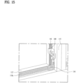
- FIG. 15 is a cross-sectional view taken along line C-C of FIG. 13
- the outlet module 140 may be inserted in the internal space of the C-shape steel 115 of the frame modules 111, 112, and 113 and may be disposed in a portion of the internal space that is open to the mounting cell 114 such that the outlet module 140 is exposed.
- FIGS. 17 and 18 are views illustrating various embodiments of the outlet module 140 of the smart wall 100 according to an embodiment of the present disclosure.
- the outlet module 140 of the present disclosure may include a base module to which a cable 144 for supplying external power is connected, the power outlet, and a power unit 141 fastened to the base module to supply power to a power plug inserted into the power outlet.
- a data module including a data port for Internet connection or a data port for connection between multimedia devices may be further added. Since the data port is smaller than the power outlet, multiple data ports may be stacked and arranged beside one power module as shown in FIG. 17 .
- the outlet module 140 may include a wing 140a that extends beyond the entrance of the second internal space 1152.
- the wing 140a may be located outside the internal space as shown in FIGS. 13 and 15 .
- the wing 140a may support the outlet module 140 such that the outlet module 140 is maintained in contact with the basket without entering the second internal space 1152 even when force is applied to the outlet module 140.
- a rail structure and outlets may be used to supply power to each multimedia device and connect the multimedia devices. Thereby, issues such as tangled wiring may be addressed.
Landscapes
- Engineering & Computer Science (AREA)
- Architecture (AREA)
- Structural Engineering (AREA)
- Civil Engineering (AREA)
- Physics & Mathematics (AREA)
- General Engineering & Computer Science (AREA)
- Electromagnetism (AREA)
- Signal Processing (AREA)
- Acoustics & Sound (AREA)
- Mechanical Engineering (AREA)
- Microelectronics & Electronic Packaging (AREA)
- Multimedia (AREA)
- Casings For Electric Apparatus (AREA)
Description
- The present disclosure relates to a wall on which a multimedia device, such as a TV and a loudspeaker, and a home appliance are mounted, and a unitized smart wall.
- Recently, as the infrastructure in which all media devices and home appliances at home beyond the smartphone are connected to the Internet is built, the smart home is emerging as a keyword of a new smart ecosystem. In particular, user experiences and values accumulated through smartphones, which are personal media devices, have begun to expand to other devices.
- As various attempts such as building a home network system were made in order to make media devices and home appliances to interoperate with each other, the number of electronic devices at home has increased and there is a hassle of connecting the devices one by one.
- In particular, it is a recent trend to minimize the number of pieces of furniture and electronics that are placed near the living room wall, around which the TV is usually placed, to keep a neat appearance of the living room wall, which represents the house. In addition, where there are children in a house, they may be pushed over or bumped and injured due to a TV table or a loudspeaker placed in the living room. Therefore, it is important to reduce the number of pieces of furniture and electronics protruding into the space of the living room.
-
DE 21 49 177 A1 discloses a low-weight composite structure made of standardized, similar and mutually connectable metal elements. -
WO 2012/109739 A1 discloses a smart wall according to the preamble ofclaim 1. - An object of the present disclosure is to provide a smart wall unitized by mounding multimedia devices, such as a TV and a loudspeaker on a wall, and home appliances.
- In one aspect of the present disclosure, according to
claim 1, a smart wall includes a plurality of frame modules including at least one mounting cell, a fastener configured to fasten the plurality of frame modules to each other to form a frame structure, a fixing member configured to fix the frame structure to a ceiling and a floor, an electronic appliance disposed in the mounting cell, and an art wall configured to cover a front surface of the frame structure, wherein the plurality of frame modules includes at least one of a first frame module including mounting cells arranged side by side in a horizontal direction, a second frame module including a mounting cell larger than the mounting cells of the first frame module, or a third frame module having a length corresponding to a vertical length of the frame structure and including mounting cells arranged side by side in a vertical direction. - The first frame module and the second frame module may be stacked in the vertical direction, wherein a horizontal length of the first frame module may be equal to a horizontal length of the second frame module.
- A sum of an integer multiple of a vertical length of the first frame module and a vertical length of the second frame module may correspond to a vertical length of the third frame module.
- Each of the frame modules may be formed by arranging, in a grid, a pair of pieces of vertical steel disposed in the vertical direction and a piece of horizontal steel between the pair of pieces of vertical steel, wherein the vertical steel and the horizontal steel may be C-shape steel having a C-shaped cross-section formed by bending both width ends thereof twice.
- The fixing member may include a fixing bracket fixed to the ceiling or floor, a coupling bracket coupled to the fixing bracket, and a first vertical bracket extending in the vertical direction from the coupling bracket and inserted into the vertical steel of the first frame module and the second frame module, wherein the first vertical bracket may be fastened to the first frame module and the second frame module.
- The third frame module may be disposed on a side of a stack of the first frame module and the second frame module, wherein the fixing member may further include a second vertical bracket inserted into the vertical steel of the third frame module.
- The mounting cells of the first frame module and the third frame module may include at least one of a first mounting cell, a second mounting cell having a horizontal dimension equal to an integer multiple of a horizontal dimension of the first mounting cell, or a third mounting cell having a vertical dimension equal to an integer multiple of a vertical dimension of the first mounting cell.
- The second mounting cell may be provided in the first frame module, and the third mounting cell may be provided in the third frame module.
- The smart wall further includes an outlet module positioned on a lateral surface of the mounting cell, and a basket inserted into the mounting cell, the basket being open forward of the frame structure and including an opening formed in a lateral surface thereof to expose the outlet module.
- The smart wall further includes a first hook formed on the frame structure, and a second hook formed on the basket and fastened to the first hook.
- The first hook may be disposed on one side of the outlet module, and wherein the second hook may be disposed outside the basket so as to be adjacent to the opening of the basket.
- The second hook is hinged to the basket, wherein one side of the second hook is arranged outside of the basket and fastened to the first hook, and an opposite side of the second hook is arranged inside the basket, wherein, when a user applies force to the second hook, the one side of the second hook is separated from the first hook.
- The smart wall may further include a pair of roller modules positioned at one side and an opposite side of the mounting cell of the second frame, a chain wound around the pair of roller modules and configured to move according to rotation of the roller, and a flexible display coupled to the chain and having a first the surface to output an image, the image being output while one side and another side of the flexible display being moved in opposite directions, wherein a position of the flexible display may be switched between a first state and a second state, wherein, in the first state, the first surface may face forward of the frame structure, and wherein, in the second state, a second surface of flexible display opposite to the first surface may face forward of the frame structure.
- In the second state, the second surface is positioned in the same plane as the art wall.
- The smart wall may further include C-shape steel having a C-shaped cross-section formed by bending both width ends thereof twice, the C-shape steel including an internal space open at one end thereof toward the mounting cell.
- The internal space may include a pair of first internal spaces surrounded in a square bracket shape at both ends of the C-shape steel, and a second internal space located between the pair of first internal spaces and including an opening open to the mounting cell, and an outlet module inserted into the second internal space and including an power outlet facing the mounting cell.
- The outlet module may include a base module connected to a cable for supplying external power, and a power unit including the power outlet and fastened to the base module to supply power to a power plug inserted into the power outlet, wherein the power unit may include a plurality of power units stacked in a longitudinal direction of the C-shape steel.
- The outlet module may further include a data unit including a data port allowing a data plug to be inserted thereinto for data communication, wherein the data unit may be arranged on a side of the power unit and stacked on top of the base module.
- A vertical length of the power unit may correspond to an integer (N) multiple of a vertical length of the data unit, wherein the data unit may include N data units stacked on a side of one of the power units.
- The outlet module may further include a wing laterally extending from an outside of the opening so as to abut an outer surface of the C-shape steel.
- The smart wall may further include a rail located in the first internal space and including a cable groove extending in the longitudinal direction of the C-shape steel, wherein the rail include a plurality of rails arranged side by side in a lateral direction of the C-shape steel.
- A smart wall according to the present disclosure may be installed on a wall at the same height as a multimedia device such as a TV or an audio device mounted thereon, and may therefore provide a tidy appearance.
- The size of the smart wall may vary depending on the installation site, and therefore may be customized.
- The smart wall may be modularized, thereby facilitating mounting of any appliance. When a repair is needed, only a module may be easily removed. Thus, installation and maintenance are simple. Additionally, when a multimedia device or an appliance is added, the smart wall may be easily extended by adding a unit.
- Further, it is not necessary to move away unused seasonal appliances into a separate mounting cell, which is advantageous in terms of securing space.
- Further scope of applicability of the present disclosure will become apparent from the detailed description below. Various changes and modifications within the scope of the present disclosure may be clearly understood by those skilled in the art, and therefore, the detailed description and specific embodiments, such as preferred embodiments of the present disclosure, should be understood as given by way of example only.
- The accompanying drawings, which are included to provide a further understanding of the disclosure and are incorporated in and constitute a part of this application, illustrate embodiment(s) of the disclosure and together with the description serve to explain the principle of the disclosure. In the drawings:
-
FIG. 1 is a view illustrating an installation example of a smart wall of the present disclosure; -
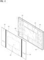
FIG. 2 is an exploded perspective view of the smart wall according to an embodiment of the present disclosure; -
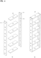
FIG. 3 is a view illustrating a configuration of frames of the smart wall according to an embodiment of the present disclosure; -
FIG. 4 shows examples of various frame structures according to a combination of frame modules of the present disclosure; -
FIG. 5 is a view illustrating a frame module of the smart wall according to an embodiment of the present disclosure; -
FIG. 6 is a view illustrating a method of installing a frame structure of the smart wall according to an embodiment of the present disclosure; -
FIG. 7 is a view illustrating a basket of the smart wall according to an embodiment of the present disclosure; -
FIG. 8 is a view illustrating a method of mounting the basket of the smart wall and a product according to an embodiment of the present disclosure; -
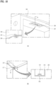
FIGS. 9 and10 are views illustrating a fixing structure of the basket; -
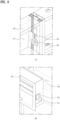
FIGS. 11 and12 are views illustrating a display of the smart wall according to an embodiment of the present disclosure; -
FIGS. 13 and 14 are views illustrating an outlet module and a rail of the smart wall according to an embodiment of the present disclosure; -
FIG. 15 is a cross-sectional view taken along line C-C ofFIG. 13 ; -
FIG. 16 shows examples of arrangement of C-shape steel including a rail of the smart wall according to an embodiment of the present disclosure; and -
FIGS. 17 and 18 are views illustrating various embodiments of the outlet module of the smart wall according to an embodiment of the present disclosure. - Hereinafter, exemplary embodiments disclosed herein will be described in detail with reference to the accompanying drawings. The same reference numbers will be used throughout the drawings to refer to the same or like parts, and redundant description thereof will be omitted. As used herein, the suffixes "module" and "unit" are added or used interchangeably to facilitate preparation of this specification and are not intended to suggest distinct meanings or functions. In the following description of the embodiments of the present disclosure, a detailed description of known technology will be omitted to avoid obscuring the subject matter of the present disclosure. The accompanying drawings are intended to facilitate understanding of the embodiments disclosed herein, and should not be construed as limiting the technical idea disclosed in the present specification. The disclosure is to cover all modifications, equivalents, and alternatives falling within the scope of the embodiments.
- Terms including ordinal numbers such as first, second, etc. may be used to explain various elements. However, it will be appreciated that the elements are not limited to such terms. These terms are merely used to distinguish one element from another.
- Stating that one constituent is "connected" or "linked" to another should be understood as meaning that the one constituent may be directly connected or linked to another constituent or another constituent may be interposed between the constituents. On the other hand, stating that one constituent is "directly connected" or "directly linked" to another should be understood as meaning that no other constituent is interposed between the constituents.
- As used herein, the singular forms "a", "an", and "the" include plural referents unless context clearly dictates otherwise.
- In this specification, terms such as "includes" or "has" are intended to indicate existence of characteristics, figures, steps, operations, constituents, components, or combinations thereof disclosed in the specification. The terms "includes" or "has" should be understood as not precluding possibility of existence or addition of one or more other characteristics, figures, steps, operations, constituents, components, or combinations thereof.
-
FIG. 1 is a view showing a wall-type frame of asmart wall 100 of the present disclosure. The present disclosure relates to asmart wall 100 systemized by integrating electronic devices used at home, such as media devices and home appliances, with a wall so as not to be exposed through the exterior of the smart wall. The present disclosure provides a total space solution that minimizes the exposure of electronic devices in a space by mounting various electronic devices such as a display, an interphone, a loudspeaker, an air purifier, a humidifier, a light, a digital clock, a router, and a set-top box on a wall. - Recently, the thickness of a
display device 161 has become thin. Thus, thesmart wall 100 of the present disclosure may be formed to have a the thickness of 15 to 20 cm, thereby preventing the interior space from being narrowed during installation. Rather, the storage furniture and ahome appliance 160 may be embedded in thesmart wall 100 to provide a neat appearance. When necessary, a part of the wall may be selectively drawn out to allow a necessary home appliance to protrude from the wall, and the space where the home appliances are not embedded may be used as a mountingcell 114 for an item such as a drawer. - Recently, it has become possible to design a thin TV, and thus a thin display is implementable. Accordingly, the TV itself may serve as a cover of a frame and may be coupled to the frame to define a front appearance. An
opening 153 may be formed in anart wall 151 to expose the display of thedisplay device 161. A cover to open and close theopening 153 may be further provided. - A display employing organic light-emitting diodes (OLED) is bendable, and therefore it may be exposed to the outside only when used and may be rolled up and kept inside the wall when not in use, thereby providing a tidy screen by appearance.
- Regarding projectors, a unifocal projector has recently been developed. This projector may be mounted on the wall and drawn out like a drawer to output images on a screen, thereby implementing a large screen. In this case, when the projector is in use, the display is unseeable from the outside of the
smart wall 100, and therefore may provide a tidier appearance. -
FIG. 2 is an exploded view of thesmart wall 100 of the present disclosure. A frame structure formed by a plurality of pieces of shape steel arranged in a grid form may be disposed inside theart wall 150, which is the front. Theframe structure 110 is a rigid member. Theframe structure 110 may support the wall so as not to collapse even when an impact is applied to the wall. A panel may be attached to the front of theframe structure 110 to hide theelectronic appliance 160 mounted on theframe structure 110, thereby looking like a wall. The front wall covered with such a panel is called anart wall 150. - The
art wall 150 may be changed according to the preference of the consumer. Theart wall 150 may be easily changed after being installed to change the mood of the home. - The
shape steel 115 arranged in a grid form may partition the mountingcell 114, and seat theelectronic appliance 160 in each of the partitioned mountingcells 114. The partitioned mountingcells 114 may have the same size or sizes which are multiples of a size. Thus, theelectronic appliance 160 to be mounted may be modularized and disposed at any position in theframe structure 110. - In addition to the
display device 161 described above, asound device 152 such as aloudspeaker 162 may be mounted in the mountingcell 114.Multiple sound devices 152 may be configured according to the number of channels. Theart wall 152 covering the sound device may be configured in a mesh form to allow sound to be output, or may selectively open and close the openings through which the sound is output, such that the openings exposed to the outside are minimized. To prevent infiltration of water, the openings may be formed using a waterproof mesh or the like. - A
dehumidifier 163, ahumidifier 165, an air conditioner, a stove, and the like, which are seasonal household appliances, may be provided. Leaving the seasonal appliances exposed to the outside when not in use may cause dust to accumulate on the appliances and undermine the appearance. Thus, the seasonal appliances are usually kept in a storage area with a cover put thereon when they are not in use. When such appliances are embedded in thesmart wall 100 in the present disclosure, they may be covered with theart wall 150 so as not to be exposed to the outside when they are not used, and therefore the need for the separate mountingcell 114 may be eliminated. - The
dehumidifier 163 or thehumidifier 165 may implement a drawer type space for collecting/storing water to remove collected water or supply water.Openings 154 through which air passes are needed to discharge water or to collect moisture in the surroundings. An air cleaner may be installed at a lower end of thesmart wall 100 to allow a user to easily open the air cleaner to periodically replace the filter with a new one. - The
openings 154 may not be necessarily formed in theart wall 150, but a gap between theart wall 150 and theframe structure 110 may be used. - In addition, when a set-top box or a Wi-Fi router is provided, a home network system may be implemented, a not only functional units mounted on the
smart wall 100 but also other electronic devices such as a computer or a mobile terminal located outside thesmart wall 100 may be connected via the Wi-Fi router and controlled in an interworking manner. - An LED or a small display panel may be arranged on an upper portion of the smart wall to provide a user with simple information such as weather, time, event information, or may be used as lighting. A light may be provided to the
smart wall 100 to obtain an interior effect. - When different communication schemes or signals are used between the devices, the router serves as an intermediate device to coordinate the schemes or signals and guide a path. In addition, a functional unit mounted on the
smart wall 100 may be connected and controlled via a WIFI router, rather than being connected by wire. - The router also serves to connect an external network and the internal network to each other. Accordingly, the user staying outside may control the router connected to the external network to control not only the functional units mounted on the
smart wall 100 but also as home appliances and media devices connected to the internal network. - In addition, the electronic devices of the
smart wall 100 may be controlled in operative connection with a mobile device. That is, when the mobile device is mounted on thesmart wall 100, media images and music on the mobile device may be output. In addition, when a video call is received through the mobile device, the image of the other party may be provided through the display of thesmart wall 100. - In addition, a wall pad connected to a camera or security system of the front door may be provided in the mounting
cell 114 of thesmart wall 100. The wall pad embedded in the existing bearing wall is difficult to repair and replace in case of failure, and there is a difficulty in changing the location thereof. However, when the wall pad is configured in a unit form and provided in thesmart wall 100, maintenance thereof is easy. - The
smart wall 100 may be installed in a room as well as the living room. The wall between the rooms may be configured as thesmart wall 100 to use thesmart wall 100 in both directions in neighboring rooms. For example, one air conditioner or air purifier may be used in both spaces when it is arranged to be reachable in both directions. Instead of the TV andloudspeaker 162 used in the living room, a monitor and a personal computer (PC) may be mounted and used based on the purpose of the room. Alternatively, another functional unit such as an electronic board may be mounted and used according to the age of a child. - When installed in an office, a
smart wall 100 equipped with functional units such as an electronic board, an air purifier, a video conference system, and a PC may be used. Theelectronic appliance 160 mounted on thesmart wall 100 is covered by theart wall 150 and thus do not require a separate exterior case. - When the
smart wall 100 is installed after being manufactured at a factory according to a user's installation location, large quantities of the same module may be manufactured and supplied to a hotel/resort or apartment under construction, thereby reducing defect rate and manufacturing costs. - However, it is difficult to transport the
smart wall 100 that has been assembled. Further, when construction of a building is completed, it is difficult to bring thesmart wall 100 into the building. Accordingly, when thesmart wall 100 is installed at the time of movement into an existing building or remodeling of the interior, thesmart wall 100 may be implemented by installing a frame in the building and inserting a unit module. In this case, for ease of installation and standardization, theframe structure 110 may be implemented using a plurality of module frames. -
FIG. 3 is a view illustrating coupling offrame modules smart wall 100 according to an embodiment of the present disclosure. In order to mount each component, bookcase-type frame modules cell 114 may be used. In order to partition the mountingcell 114, theframe modules - The
frame modules first frame module 111 having mountingcells 114 arranged side by side in a horizontal direction, asecond frame module 112 provided to mount alarge appliance 160 such as thedisplay device 161, athird frame module 113 having mountingcells 114 arranged side by side in a vertical direction. - The
second frame module 112 includes a large space to allow thedisplay device 161 of any size to be mounted therein. When necessary, as shown inFIG. 4 , beams to partition the mountingcell 114 may be provided to fix thedisplay device 161 and to enhance rigidity of theframe structure 110. - The
first frame module 111 and thesecond frame module 112 may be stacked in a vertical direction. The horizontal length of thefirst frame module 111 may be the same as the horizontal length of thesecond frame module 112. Thus, when the modules are stacked in the vertical direction, they may be disposed so as not to be misaligned. - The
first frame module 111 may be disposed both over and under thesecond frame module 112. The number offirst frame modules 111 stacked in the vertical direction may be increased or decreased depending on the sizes of thefirst frame module 111 and thesecond frame module 112 or the size of the installation space. - The
third frame module 113, in which the mountingcells 114 are arranged side by side in the vertical direction, may have the same height as that of thefirst frame module 111 and thesecond frame module 112 stacked in the vertical direction. As shown inFIG. 4 , thethird frame module 113 may be located on the lateral sides of thefirst frame module 111 and thesecond frame module 112. Theframe modules frame structure 110 having a rectangular parallelepiped shape. -
FIG. 4 is a view illustrating a method of manufacturing theframe modules third frame module 113 in which the mountingcells 114 are arranged in the vertical direction will be described as an example. Each of theframe modules shape steel 115 extending in one direction. The shape steel is a structural member and represents all rod-shaped members having various cross-sectional shapes. Rod-shaped steel having the same cross section in the longitudinal direction may be formed by rolling or by bending a sheet material. The shape steel has a hollow space compared to a beam-shaped member having a circular or rectangular cross section. Thus, it is a lightweight member obtaining rigidity greater than or equal to a predetermined value with a little amount of material. - As shown in
FIG. 4 , the present disclosure may employ C-shape steel 115 having a C-shaped cross section. The C-shape steel 115 may be formed by vertically bending both width ends of a metal plate. When both ends of the metal plate are vertically bent only once, the plate may have a square bracket-shaped cross section. When both ends of the metal plate are vertically bent twice, the plate may have a C-shaped cross section. A power line or signal line connected to theelectronic appliance 160 may be disposed in the internal space of the steel, and anoutlet module 140 to which a power cable or a data cable is fastened may be disposed. - The
outlet module 140 may include a power terminal for supplying power, a data terminal for data transmission and reception such as an Internet line or a cable input, and a connector by which a functional unit inserted into the frame is connected to another functional unit. The connector has terminals on both sides of the frame. When data connection lines of electronic devices are inserted into the terminals, the devices may exchange data with each other. Theoutlet module 140 may include a rail structure that moves along theframe modules - A
vent hole 116 may be formed in theshape steel 115 as shown inFIG. 4 . Thevent hole 116 may reduce the weight of theshape steel 115 and discharge heat generated from theelectronic appliance 160. A fan may also be used to discharge hot air to the outside to more actively discharge heat. When the heat of theelectronic appliance 160 is discharged into an indoor space, a heating effect may be obtained in winter. However, in summer, discharging the heat into the indoor space may cause the indoor temperature to rise. Thus, the fan may be used to internally circulate heat, or a structure to discharge heat to the outside may be added to the wiring connected to the outdoor unit of the air conditioner. - Each of the
frame modules cell 114. The outer steel may include vertical steel extending in the vertical direction and horizontal steel extending in the horizontal direction. Thefirst frame module 111 to thethird frame module 113 may be assembled by arranging the horizontal steel between a pair of vertical steels. In order to fasten the vertical steel with a fixingmember 120, which is fixed to the ceiling and the floor, the upper and lower ends of the vertical steel may need to be exposed. Therefore, the vertical steel may be arranged outside the horizontal steel may be fastened by insertingvertical brackets member 120 to the end of the vertical steel (SeeFig. 6 ). - The inner steel positioned inside the outer steel may define the mounting
cell 114 by partitioning a space surrounded by the outer steel. The inner steel may be immovably connected to the outer steel by welding, and part of the inner steel may be bolted or hooked so as to be removed when necessary. - Thus, by fascinating the
frame modules semi-finished appliance 160 in the above-described manner, the number of connection operations to be performed on the site may be reduced. The dimensions of theappliance 160 may be kept constant and the installation time may be reduced. In addition, the product may be modularized into a size that facilitates movement of the product, and therefore may be easily moved to the site. -
FIG. 5 shows examples ofvarious frame structures 110 according to a combination of theframe modules FIG. 5(a) illustrates assembly of aframe structure 110 consisting of a pair of first frame modules 111a, onesecond frame module 112a, and a pair ofthird frame modules 113. Since the first frame module 111a has four mountingcells 114, the width of the first frame module 111a may not fit to a narrow indoor space for installation. - Accordingly, as shown in
FIG. 5(b) , afirst frame module 111b having three mountingcells 114 to have a short horizontal length may be used. Thesecond frame module 112b may have a length corresponding to the horizontal length of thefirst frame module 111b. - In addition, the
third frame modules 113 may be disposed on both sides of the vertical stack of thefirst frame module 111 and thesecond frame module 112. The height of a typical house is 220 cm to 230 cm, thethird frame module 113 may be configured to have a height a little less than 220 cm. While a five-stage vertical frame is illustrated in the drawings, a six-stage vertical frame may be manufactured in case of a multilayer house or a house having a great floor height. - When installed in a narrower space, the
frame structure 110 may be configured using only the first frame module 111a and thesecond frame module 112a without thethird frame module 113. When alarge display device 161 is not mounted, only the third frame modules may be arranged in a line to implement theframe structure 110. Eachframe module -
FIG. 6 is a view illustrating a method of installing aframe structure 110 of thesmart wall 100 according to an embodiment of the present disclosure. Theframe structure 110 formed by fastening theframe modules - The fixing
bracket 125, which is installed on the ceiling or the floor, is a member bent in an L shape. Oneside 125b of the fixingbracket 125 is disposed on the ceiling or the floor, and theopposite side 125a thereof vertically extends from the ceiling or the floor. The frame structure may include a firstvertical bracket 122 inserted into an internal space of the vertical steel thereof. - The first
vertical bracket 122 may be formed to be longer than the vertical length of thefirst frame module 111 to fasten not only thefirst frame module 111 but also thesecond frame module 112. The frame structure may further include a secondvertical bracket 123 disposed in parallel with the firstvertical bracket 122 and inserted into thethird frame module 113. Since the vertical steel of thethird frame module 113 is one member, the vertical steel does not need to be as long as the firstvertical bracket 122. - A
coupling bracket 121 may be coupled to an end of each of the firstvertical bracket 122 and the secondvertical bracket 123 to form a T-shape together with thevertical brackets coupling bracket 121 may include aseating portion 121b coupled to thevertical brackets first frame module 111 and thethird frame module 113, and afastening portion 121a vertically extending from theseating portion 121b and fastened to the fixingbracket 125. Thecoupling bracket 121 and the fixingbracket 125 may be fastened to each other using a screw, and may each have a fastening hole, which the screw is fastened. The fastening hole may be vertically elongated such that the brackets may be adjusted according to the ceiling height. - When the
smart wall 100 is installed on the existing wall, a fixingmember 120 may be further provided to fasten the smart wall to the existing wall. - A sound device such as the
loudspeaker 162 is positioned on thesmart wall 100. Accordingly, when thesmart wall 100 is used as a temporary wall, spaces separated by the wall are formed. In this case, thesmart wall 100 may be fixed by adding a soundproof structure to prevent sound from leak to the two spaces through the ceiling, the floor, and the sidewalls which are in contact with thesmart wall 100. -
FIG. 7 is a view illustrating abasket 130 of thesmart wall 100 according to an embodiment of the present disclosure. Theframe modules cells 114 using theinner shape steel 115. As shown inFIG. 7 , thebasket 130 may be inserted into the mountingcells 114 to provide a space in which theelectronic appliance 160 is seated. Thesecond frame module 112 has a relativelylarge mounting cell 1144 because thedisplay device 161 is located therein. On the other end, the mountingcells 114 of thefirst frame module 111 and thethird frame module 113 may be formed to have standardized sizes. Using the mountingcells 114 of the standardized sizes, thebasket 130 may also be standardized. Thereby, the number of types of parts may be reduced. - However, when the mounting cells are formed to have the same size, a larger space may be needed depending on the
electronic appliance 160 to be mounted. For example, since the size of the air conditioner is different from that of the air cleaner, the mountingcell 114 may be formed to have a size which is an integer multiple of a base size in consideration of the difference in size. For example, based on afirst mounting cell 1141 having a horizontal dimension equal to a and a vertical dimension equal to b, asecond mounting cell 1142 having a horizontal dimension equal to an integer multiple of a or athird mounting cell 1143 having a vertical dimension equal to an integer multiple of b may be provided. - The horizontal dimension of the first mounting
cell 1141 corresponds to the horizontal dimension of thethird frame module 113, and the vertical dimension thereof corresponds to the vertical dimension of thefirst frame module 111. Here, the mountingcell 114 refers to an internal space partitioned by theshape steel 115, and thus the difference in size between thefirst frame module 111 and thethird frame module 113 caused by the thickness of theshape steel 115 is ignored. - Since the
first frame module 111 has a short vertical length, thefirst frame module 111 may include only the first mountingcell 1141 and thesecond mounting cell 1142. Since thethird frame module 113 has a short horizontal length, thethird frame module 113 may include only the first mountingcell 1141 and thethird mounting cell 1143. -
FIG. 8 is a view illustrating a method of mounting thebasket 130 of thesmart wall 100 and anappliance 160 according to an embodiment of the present disclosure. Thebasket 130 is a box-shaped member having an open front. The lateral surfaces of thebracket 130 may be fastened to theframe modules FIG. 8(a) , thebracket 130 is provided with anopening 131 in the lateral surfaces thereof to expose an outlet for connecting a power cable or a data cable. Afastening structure 132 for fixing theappliance 160 may be included in thebasket 130. - A
hook groove 132 may be formed in thebasket 130 and ahook 160a that may be hooked in thehook groove 132 may be coupled to the back of theelectronic appliance 160. Thereby, theelectronic appliance 160 may be fastened to thebasket 130 as shown inFIG. 8(b) . - The
electronic appliance 160 may be spaced apart from thebasket 130 to discharge heat generated from theelectronic appliance 160. Thebasket 130 may further include an opening for discharging heat, and thehook groove 132 may be formed through thebasket 130 in a penetrating manner to discharge heat generated from theelectronic appliance 160 therethrough. -
FIGS. 9 and10 are views illustrating a fixing structure of thebasket 130. Thebasket 130 further includes a fastening structure configured to fix thebasket 130 to theframe modules FIG. 9(a) , afirst hook 145 is disposed on theoutlet module 140 arranged in each mountingcell 114, and asecond hook 133 is disposed on the outer surface of thebasket 130. As thefirst hook 145 is integrated with theoutlet module 140, thesecond hook 133 may be arranged adjacent to the opening for exposing theoutlet module 140 as shown inFIG. 9(b) . - The
first hook 145 may be formed on theframe modules second hook 133 to be engaged with thefirst hook 145 may be implemented in a lever shape. The lever-shapedsecond hook 133 may be hinged to theframe modules second hook 133 may be engaged with thefirst hook 145, and the opposite side thereof is located inside thebasket 130. When the part of thesecond hook 133 located inside thebasket 130 is pulled, thesecond hook 133 may be separated from thefirst hook 145 and thus thebasket 130 may be removed. When the user inserts thebasket 130 into the mounting cell, one side of thesecond hook 133 may be engaged with thefirst hook 145. In this embodiment, thesecond hook 133 may serve as a handle that may be held by hand, and thus enhance convenience in installing or removing the basket 13. - Alternatively, as shown in
FIG. 10(b) , anelastic member 117 may be coupled to theframe module projection 136 to be inserted into the groove formed in theelastic member 117 may be provided to thebasket 130. Thus, thebasket 130 may be fixed to theframe module -
FIGS. 11 and12 are views illustrating adisplay 1611 of thesmart wall 100 according to an embodiment of the present disclosure. Thedisplay device 161 including thedisplay 1611 configured to provide images may be mounted in thesecond frame module 112, and an opening may be formed in theart wall 150 such that thedisplay 1611 is always exposed. Alternatively, theart wall 150 may be selectively opened and closed to expose thedisplay 1611 of thedisplay device 161. Theart wall 150, which covers thedisplay 1611, may be opened or closed in a sliding manner, or may be opened or closed in a rolling manner like a roll blind. - As the
display 1611, aflexible display 1611 of a flexible material that is bendable may be employed. Theflexible display 1611 refers a lightweight, unbreakable, sturdy display while maintaining the characteristics of a conventional flat panel display. The flexible display is manufactured on a thin and flexible substrate that may be warped, bent, folded, twisted or curled like paper - The
flexible display 1611 may employ organic light-emitting diodes (OLEDs). Since the OLED generates light by itself, it does not require a backlight unit to supply light. Thus, a flexible material may be used when the OLED is employed. In addition, electronic paper, which represents a display technology providing the characteristics of general inks, uses reflected light, which is the difference from that of a conventional flat panel display. Electronic paper may change information using twisted balls or electrophoresis, which uses capsules. - When the
flexible display 1611 is in a undeformed state (hereinafter referred to as a default state) (for example, the flexible display has an infinite radius of curvature), the display area of theflexible display 1611 is flat. When theflexible display 1611 in the default state is deformed by an external force (for example, the flexible display has a finite radius of curvature, hereinafter referred to as a deformed state), the display area may be a curved surface. As shown in the figure, the information displayed in the deformed state may be visual information output on the curved surface. The visual information is implemented by independently controlling light emission of unit pixels (sub-pixels) disposed in a matrix form. The unit pixel refers to a minimum unit for implementing one color. - In the default state, the
flexible display 1611 may be in a curved position (for example, a vertically or horizontally curved position) rather than a flat position. In this case, when external force is applied to theflexible display 1611, theflexible display 1611 may be deformed into a flat position (or less curved position) or a more curved position. Theflexible display 1611 may be wound around a roll a plurality of times and mounted inside the frame. Theflexible display 1611 may be unrolled when the user wants to view an image. - The
display device 161 may be implemented by being wound around a roll by only a half turn rather than being wound by a plurality of turns. Thedisplay device 161 of this embodiment includes a pair ofroller modules 1615 coupled to thesecond frame module 112, and achain 1612 wound around the pair ofroller modules 1615 and configured to be moved according to rotation of the roller modules, and aflexible display 1611 coupled to thechain 1612 and configured to output an image on afirst surface 1611a while one side and an opposite side thereof moving in opposite directions. -
FIG. 12(a) is a view showing one side of the second frame module,FIG. 12(b) is a cross-sectional view taken along line A-A ofFIG. 1 1(a) , andFIG. 12(c) is a cross-sectional view taken along line B-B ofFIG. 11(b) . While theroller modules 1615 are illustrated in the drawings as being positioned on the upper and lower portions of thesecond frame module 112, respectively, the roller modules may be positioned on one side and the opposite side of thesecond frame module 112 facing away from each other in the horizontal direction. For simplicity, it is assumed that a pair ofroller modules 1615 is positioned on the upper and lower portions of thesecond frame module 112, and theflexible display 1611 is vertically moved. - The
roller module 1615 may employ one roller having a large diameter. Alternatively, as shown inFIG. 12 , a large roller and a small roller may constitute oneroller module 1615. Thechain 1612 wound around the pair ofroller modules 1615 may form a closed curve as shown inFIG. 12(b) , and move as theroller modules 1615 rotate. - The
roller module 1615 does not need to be formed in the shape of a rod covering the entire one side of thesecond frame module 112. Theroller module 1615 may be configured by positioning discs at both ends of a rotation shaft so as to rotate about the rotation shaft, as shown inFIG. 12(a) . - The
chain 1612 may be formed to be small so as to correspond to the size of theroller modules 1615 as shown inFIG. 12(a) . To ensure stable movement of theflexible display 1611, a pair ofchains 1612 may be provided on both side of the flexible display. In this embodiment, theflexible display 1611 may be moved along a pair ofchains 1612 with both left and right ends thereof coupled to thechains 1612. Theflexible display 1611 may be moved while being wound around theroller modules 1615. -
FIG. 11(a) and12(b) illustrate a first state in which afirst surface 1611a on which an image is output faces forward.FIG. 11(b) and12(c) illustrate a second state in which asecond surface 1611b on which an image is not output faces forward as an opposite surface of thefirst surface 1611a. As shown inFIG. 12(b) , in the first state, thedisplay 1611 may be located inside the frame. As shown inFIG. 12(c) , in the second state, thedisplay 1611 may be disposed father to the front than in the first state. - In the second state, the
second surface 1611b of thedisplay 1611 may realize a color and surface harmonized with theart wall 150, thereby implementing a uniform appearance in the second state. In addition, in the second state, thesecond surface 1611b of thedisplay 1611 may be arranged to form the same plane as theart wall 150. - Each device may be provided with a remote controller in order to control the functional units mounted on the
smart wall 100. However, in this case, use of the devices may be inconvenient. An integrated remote controller may be used to control the functional units mounted on thesmart wall 100 simultaneously. The integrated remote controller may control each device individually. The integrated remote controller may control each functional unit through a set-top box that integrally controls the functional units. -
FIGS. 13 and 14 are views illustrating anoutlet module 140 and arail 118 of the smart wall according to an embodiment of the present disclosure, andFIG. 15 is a cross-sectional view taken along line C-C ofFIG. 13 . Theoutlet module 140 may be inserted in the internal space of the C-shape steel 115 of theframe modules cell 114 such that theoutlet module 140 is exposed. - Referring to
FIG. 15 , the internal space of the C-shape steel 115 has a pair of firstinternal spaces 1151 enclosed in a square bracket shape on both width sides, and a secondinternal space 1152 opened to the mountingcell 114 and positioned between the firstinternal spaces 1151. A pair ofrails 118 may be installed in the pair of the firstinternal space 1151, and theoutlet module 140 may be disposed therebetween. - As shown in
FIG. 13 , therail 118 may extend in the same direction as extension of the C-shape steel 115 and include at least onecable groove 118a extending in the longitudinal direction. Acable 144 connected to theoutlet module 140 may be inserted into the groove, and thus the groove may prevent thecable 144 from being twisted and arranged in a disorderly manner.Multiple cable grooves 118a may be formed in therail 118 in parallel with each other to accommodatemultiple cables 144. Whenmultiple cables 144 are arranged in the internal space, it is difficult to distinguish between acable 144 connected to an electronic appliance, apower cable 144, and adata cable 144, which may cause inconvenience in maintenance and assembly. Thecables 144 may be inserted into the designatedcable grooves 118a to prevent confusion between various types ofcables 144. - As shown in
FIG. 14 , therail 118 may also be installed in a C-shape steel 115 on which theoutlet module 140 is not installed. Thecables 144 including a cable for supplying power to theoutlet module 140, a signal line connected to the outside such as the Internet, and acable 144 of the plug inserted into the outlet of theoutlet module 140 may all be accommodated in thecable grooves 118a of therail 118. -
FIG. 16 shows examples of arrangement of the C-shape steel 115 including therail 118 of thesmart wall 100 according to an embodiment of the present disclosure. At least oneoutlet module 140 is needed in each mountingcell 114, and therail 118 may be disposed in consideration of a position where theoutlet module 140 is disposed. - As described with reference to
FIG. 14 , a rail may be further installed in a position where theoutlet module 140 is not disposed. As shown inFIG. 16 , arranging theoutlet modules 140 at positions where the first to third frame modules overlap each other may prevent the cables connected to theoutlet modules 140 from unnecessarily extending a long distance. -
FIGS. 17 and 18 are views illustrating various embodiments of theoutlet module 140 of thesmart wall 100 according to an embodiment of the present disclosure. Theoutlet module 140 of the present disclosure may include a base module to which acable 144 for supplying external power is connected, the power outlet, and apower unit 141 fastened to the base module to supply power to a power plug inserted into the power outlet. - In addition to the
power unit 141, a data module including a data port for Internet connection or a data port for connection between multimedia devices may be further added. Since the data port is smaller than the power outlet, multiple data ports may be stacked and arranged beside one power module as shown inFIG. 17 . - Accordingly, the
power unit 141 may be formed to have a height correspond to N times (an integer multiple of) the height of thedata unit 142 to arrange thepower unit 141 and thedata units 142 side by side on thebase unit 143. Alternatively, when two or more power plugs are required or a plurality of data porters is required, the power plugs or data ports may be stacked as illustrated inFIG. 18 . Eachpower unit 141 may provide power supplied from thebase unit 143 to anotherpower unit 141 stacked thereon, and thusmultiple power units 141 may be connected to onebase unit 143. - The
outlet module 140 has a width corresponding to the size of the secondinternal space 1152. Anoutlet module 140 having a thickness greater than the thickness of the C-shape steel 115 may protrude into the mountingcell 114, and therefore theoutlet module 140 may have a size corresponding to the size of the secondinternal space 1152. - When the
outlet module 140 is arranged excessively deep into the secondinternal space 1152, theoutlet module 140 exposed through the opening of the basket may be spaced apart from the opening. Even arranging theoutlet module 140 in contact with thebasket 130 may cause theoutlet module 140 to move into the internal space of the C-shape steel 115 when a plug is inserted. - In order to address such issues, the
outlet module 140 may include awing 140a that extends beyond the entrance of the secondinternal space 1152. Thewing 140a may be located outside the internal space as shown inFIGS. 13 and15 . Thewing 140a may support theoutlet module 140 such that theoutlet module 140 is maintained in contact with the basket without entering the secondinternal space 1152 even when force is applied to theoutlet module 140. - As is apparent from the above description, the
smart wall 100 may be installed on a wall at the same height as a multimedia device such as a TV or an audio device mounted thereon, and may therefore provide a tidy appearance. - The size of the
smart wall 100 may vary depending on the installation site, and therefore may be customized. - A rail structure and outlets may be used to supply power to each multimedia device and connect the multimedia devices. Thereby, issues such as tangled wiring may be addressed.
- The smart wall may be modularized, thereby facilitating mounting of any appliance. When a repair is needed, only a module may be easily removed. Thus, installation and maintenance are simple. Additionally, when a multimedia device or an appliance is added, the smart wall may be easily extended by adding a unit.
- Further, it is not necessary to move away unused seasonal appliances into a separate mounting
cell 114, which is advantageous in terms of securing space.
Claims (12)
- A smart wall comprising:a plurality of frame modules (111, 112, 113) including at least one mounting cell;a fastener configured to fasten the plurality of frame modules (111, 112, 113) to each other to form a frame structure;a fixing member (120) configured to fix the frame structure to a ceiling and a floor;a first hook (145) formed on the frame structure;an outlet module (140) positioned on a lateral surface of the mounting; and an electronic appliance (160); andan art wall (150) configured to cover a front surface of the frame structure,wherein the plurality of frame modules (111, 112, 113) comprises at least one of:a first frame module (111) including mounting cells arranged side by side in a horizontal direction;a second frame module (112) including a mounting cell larger than the mounting cells of the first frame module (111); ora third frame module (113) having a length corresponding to a vertical length of the frame structure and including mounting cells arranged side by side in a vertical direction,whereinthe outlet module (140) is configured for a power cable or a data cable to be fastened thereto;the smart wall further comprises a basket (130) inserted into the mounting cell, the basket being open forward of the frame structure and including an opening formed in a lateral surface thereof to expose the outlet module (140); andthe electronic appliance (160) is disposed in the basket (130),characterized in that the smart wall further comprises a second hook (133) hinged to the basket (130) and fastened to the first hook (145),wherein one side of the second hook (133) is arranged outside of the basket (130) and fastened to the first hook (145), and an opposite side of the second hook (133) is arranged inside the basket (130), andwherein, when a user applies force to the second hook (133), the one side of the second hook (133) is separated from the first hook (145).
- The smart wall of claim 1, wherein the first frame module (111) and the second frame module (112) are stacked in the vertical direction,
wherein a horizontal length of the first frame module (111) is equal to a horizontal length of the second frame module (112). - The smart wall of claim 2, wherein a sum of an integer multiple of a vertical length of the first frame module (111) and a vertical length of the second frame module (112) corresponds to a vertical length of the third frame module (113).
- The smart wall of claim 2, wherein each of the frame modules (111, 112, 113) is formed by arranging, in a grid, a pair of pieces of vertical steel disposed in the vertical direction and a piece of horizontal steel between the pair of pieces of vertical steel,wherein the vertical steel and the horizontal steel are C-shape steel having a C-shaped cross-section formed by bending both width ends thereof twice,wherein the fixing member (120) comprises:a fixing bracket (125) fixed to the ceiling or floor;a coupling bracket (121) coupled to the fixing bracket (125); anda first vertical bracket (122) extending in the vertical direction from the coupling bracket (121) and inserted into the vertical steel of the first frame module (111) and the second frame module; andwherein the first vertical bracket (122) is fastened to the first frame module (111) and the second frame module (112).
- The smart wall of claim 4, wherein the third frame module (113) is disposed on a side of a stack of the first frame module (111) and the second frame module (112),
wherein the fixing member (120) further comprises a second vertical bracket inserted into the vertical steel of the third frame module (113). - The smart wall of one of claims 2 to 5, wherein the mounting cells of the first frame module (111) and the third frame module (113) comprise at least one of:a first mounting cell (1141);a second mounting cell (1142) having a horizontal dimension equal to an integer multiple of a horizontal dimension of the first mounting cell (1141), wherein the second mounting cell (1142) is provided in the first frame module (111); ora third mounting cell (1143) having a vertical dimension equal to an integer multiple of a vertical dimension of the first mounting cell (1141), wherein the third mounting cell (1143) is provided
- The smart wall of one of claims 1 to 6, further comprising:a pair of roller modules (1615) positioned at one side and an opposite side of the mounting cell of the second frame;a chain (1612) wound around the pair of roller modules and configured to move according to rotation of the roller; anda flexible display (1611) coupled to the chain and having a first the surface to output an image, the image being output while one side and another side of the flexible display being moved in opposite directions,wherein a position of the flexible display (1611) is switched between a first state and a second state,wherein, in the first state, the first surface faces forward of the frame structure, andwherein, in the second state, a second surface of flexible display opposite to the first surface faces forward of the frame structure.
- The smart wall of one of claims 1 to 7, further comprising:C-shape steel (115) having a C-shaped cross-section formed by bending both width ends thereof twice, the C-shape steel (115) including an internal space open at one end thereof toward the mounting cell,wherein the internal space comprises:a pair of first internal spaces (1151) surrounded in a square bracket shape at both ends of the C-shape steel; anda second internal space (1152) located between the pair of first internal spaces and including an opening open to the mounting cell; andwherein the smart wall further comprises an outlet module inserted into the second internal space and including a power outlet facing the mounting cell.
- The smart wall of claim 8, wherein the outlet module (140) comprises:a base module connected to a cable for supplying external power; anda power unit (141) including the power outlet and fastened to the base module to supply power to a power plug inserted into the power outlet,wherein the power unit (141) comprises a plurality of power units stacked in a longitudinal direction of the C-shape steel (115).
- The smart wall of claim 9, wherein the outlet module (140) further comprises:a data unit (142) including a data port allowing a data plug to be inserted thereinto for data communication,wherein the data unit (142) is arranged on a side of the power unit (141) and stacked on top of the base module.
- The smart wall of one of claims 8 to 10, wherein the outlet module (140) further comprises a wing (140a) laterally extending from an outside of the opening so as to abut an outer surface of the C-shape steel.
- The smart wall of one of claims 8 to 11, further comprising a rail (118) located in the first internal space and comprising a cable groove (118a) extending in the longitudinal direction of the C-shape steel (115),
wherein the rail (118) comprises a plurality of rails arranged side by side in a lateral direction of the C-shape steel (115).
Applications Claiming Priority (3)
| Application Number | Priority Date | Filing Date | Title |
|---|---|---|---|
| KR20180092835 | 2018-08-09 | ||
| KR1020190049981A KR102650347B1 (en) | 2018-08-09 | 2019-04-29 | Medea wall |
| KR1020190049980A KR102650346B1 (en) | 2018-08-09 | 2019-04-29 | Medea wall |
Publications (2)
| Publication Number | Publication Date |
|---|---|
| EP3733990A1 EP3733990A1 (en) | 2020-11-04 |
| EP3733990B1 true EP3733990B1 (en) | 2024-07-10 |
Family
ID=69669842
Family Applications (1)
| Application Number | Title | Priority Date | Filing Date |
|---|---|---|---|
| EP20150180.6A Active EP3733990B1 (en) | 2018-08-09 | 2020-01-03 | Smart wall |
Country Status (4)
| Country | Link |
|---|---|
| US (1) | US10874028B2 (en) |
| EP (1) | EP3733990B1 (en) |
| KR (2) | KR102650347B1 (en) |
| CN (1) | CN111851889A (en) |
Families Citing this family (19)
| Publication number | Priority date | Publication date | Assignee | Title |
|---|---|---|---|---|
| CN107574956A (en) * | 2017-10-25 | 2018-01-12 | 苏州朗捷通智能科技有限公司 | Integrated monitoring video wall |
| JP1704672S (en) * | 2019-09-26 | 2022-01-14 | Interior walls with built-in appliances | |
| JP1704668S (en) * | 2019-09-26 | 2022-01-14 | Interior walls with built-in appliances | |
| JP1708821S (en) * | 2019-09-26 | 2022-03-02 | Interior wall integrated with built-in home appliances | |
| USD963619S1 (en) * | 2019-10-28 | 2022-09-13 | Lg Electronics Inc. | Basket for a wall with built-in home appliances |
| JP1711823S (en) * | 2019-10-28 | 2022-04-06 | Wall basket with built-in appliances | |
| USD930625S1 (en) * | 2019-11-04 | 2021-09-14 | Lg Electronics Inc. | Basket for a frame of built-in home appliances |
| USD931259S1 (en) * | 2019-11-04 | 2021-09-21 | Lg Electronics Inc. | Basket for a frame of built-in home appliances |
| USD930626S1 (en) * | 2019-11-04 | 2021-09-14 | Lg Electronics Inc. | Basket for a frame of built-in home appliances |
| USD922355S1 (en) * | 2019-11-04 | 2021-06-15 | Lg Electronics Inc. | Frame for built-in home appliances |
| USD922356S1 (en) * | 2019-11-04 | 2021-06-15 | Lg Electronics Inc. | Frame for built-in home appliances |
| USD933639S1 (en) * | 2019-11-07 | 2021-10-19 | Lg Electronics Inc. | Basket for a wall with built-in home appliances |
| JP1706496S (en) * | 2019-11-21 | 2022-02-01 | Interior wall connecting members with built-in home appliances | |
| WO2021100915A1 (en) * | 2019-11-21 | 2021-05-27 | 엘지전자 주식회사 | Smart wall |
| WO2021182659A1 (en) * | 2020-03-11 | 2021-09-16 | 엘지전자 주식회사 | Smart wall |
| KR102732688B1 (en) | 2020-09-03 | 2024-11-20 | 엘지전자 주식회사 | Display device |
| KR102434136B1 (en) * | 2020-11-11 | 2022-08-18 | 동서대학교 산학협력단 | Service system using digital wall screen device |
| KR102448910B1 (en) | 2021-06-10 | 2022-09-30 | 한국건설기술연구원 | Variable Smart Wall System |
| KR102832559B1 (en) * | 2024-09-23 | 2025-07-10 | 디자인토큰 주식회사 | Sound room module system |
Family Cites Families (30)
| Publication number | Priority date | Publication date | Assignee | Title |
|---|---|---|---|---|
| FR2109129A5 (en) | 1970-10-02 | 1972-05-26 | Vincens Rene | |
| DE2149177B2 (en) * | 1970-10-02 | 1979-08-23 | S.A. Pour L'etude Et La Promotion Des Entreprises, Freiburg (Schweiz) | Carrier for connecting with other similar components for supporting structures for buildings and room facilities |
| JP2566735Y2 (en) * | 1993-09-29 | 1998-03-30 | 株式会社岡村製作所 | Partition outlet device |
| US5924779A (en) * | 1996-11-01 | 1999-07-20 | Wenger Corporation | Music library system |
| US6230445B1 (en) * | 1999-04-26 | 2001-05-15 | Steelcase Development Inc. | Adjustable rack for partition system |
| US6301837B1 (en) * | 2000-03-13 | 2001-10-16 | Kewaunee Scientific Corp. | Rack assembly for supporting electronic units |
| US6851226B2 (en) * | 2002-02-15 | 2005-02-08 | Steelcase Development Corporation | Partition panel with modular appliance mounting arrangement |
| US7562949B1 (en) * | 2002-07-17 | 2009-07-21 | Furniture Designs By Aspen (Mauritius) Limited | Adjustable furniture systems to accommodate objects of various dimensions |
| US7337024B1 (en) * | 2006-06-02 | 2008-02-26 | Graham Jonathan W | Flat panel display concealment and viewing apparatus and method |
| US7866622B2 (en) * | 2007-01-05 | 2011-01-11 | Milestone Av Technologies Llc | In-wall mount |
| KR20090116162A (en) * | 2008-05-06 | 2009-11-11 | (주)엘지하우시스 | Variable storage wall with excellent sound insulation |
| GB2476225B (en) * | 2009-10-14 | 2014-05-07 | Mode Al Ltd | Improvements in racking systems |
| CN201894525U (en) * | 2010-11-01 | 2011-07-13 | 广州市浩云安防科技工程有限公司 | Television splicing wall and combined television splicing wall |
| KR101210092B1 (en) * | 2010-11-05 | 2012-12-07 | 대림산업 주식회사 | Art Wall with Air Filtering |
| US8657133B2 (en) * | 2010-12-10 | 2014-02-25 | Ameriwood Industries, Inc. | Customizable mounting system for furniture |
| US8678523B2 (en) * | 2011-02-02 | 2014-03-25 | James E. Carr | Universal television lift with enclosure |
| CA2916731C (en) * | 2011-02-17 | 2020-03-24 | Millson Custom Solutions Inc. | Mounting apparatus for an audio/video system and related methods and systems |
| EP2718511B1 (en) * | 2011-06-11 | 2016-10-12 | Dirtt Environmental Solutions, Ltd. | Modular wall nesting system |
| WO2013101298A1 (en) * | 2011-12-28 | 2013-07-04 | Dirtt Environmental Solutions Inc. | Modular walls incorporating recessed, extendable furniture |
| US8970795B2 (en) * | 2013-04-26 | 2015-03-03 | Alain Lemieux | Sliding panels system for hiding a flat screen TV |
| WO2015017671A2 (en) * | 2013-08-01 | 2015-02-05 | Urbaneer LLC | Apparatus and method for reconfigurable space |
| WO2016070280A1 (en) * | 2014-11-06 | 2016-05-12 | Cinnos Technologies, Inc. | Smart mission critical rack |
| CN105696754A (en) * | 2014-12-10 | 2016-06-22 | 顺和系统有限公司 | Modular decorative wall panel |
| JP6497219B2 (en) | 2015-05-29 | 2019-04-10 | 株式会社イトーキ | Adjuster device for partition panel |
| US9936826B2 (en) * | 2015-08-21 | 2018-04-10 | Apple Inc. | Modular wall system for displaying a product |
| ITUB20169963A1 (en) * | 2016-01-13 | 2017-07-13 | Federico Lestini | Modular building structure with integrated systems |
| KR102470945B1 (en) * | 2016-06-15 | 2022-11-25 | 엘지전자 주식회사 | Mobile terminal |
| KR102484505B1 (en) * | 2016-06-20 | 2023-01-05 | 엘지디스플레이 주식회사 | Rollable display device |
| US10433439B2 (en) * | 2016-09-19 | 2019-10-01 | Philip Pecorino | Cover for an ultra-flat panel display |
| CN108487566A (en) * | 2018-03-29 | 2018-09-04 | 绵阳鑫满顺网络科技有限公司 | A kind of network monitoring video wall |
-
2019
- 2019-04-29 KR KR1020190049981A patent/KR102650347B1/en active Active
- 2019-04-29 KR KR1020190049980A patent/KR102650346B1/en active Active
-
2020
- 2020-01-03 EP EP20150180.6A patent/EP3733990B1/en active Active
- 2020-01-29 US US16/776,306 patent/US10874028B2/en active Active
- 2020-02-11 CN CN202010087321.5A patent/CN111851889A/en active Pending
Also Published As
| Publication number | Publication date |
|---|---|
| US20200344910A1 (en) | 2020-10-29 |
| KR102650347B1 (en) | 2024-03-25 |
| KR20200018214A (en) | 2020-02-19 |
| EP3733990A1 (en) | 2020-11-04 |
| CN111851889A (en) | 2020-10-30 |
| KR20200018213A (en) | 2020-02-19 |
| US10874028B2 (en) | 2020-12-22 |
| KR102650346B1 (en) | 2024-03-25 |
Similar Documents
| Publication | Publication Date | Title |
|---|---|---|
| US10874028B2 (en) | Smart wall | |
| US11000126B1 (en) | Smart wall | |
| US10932385B1 (en) | Media wall | |
| KR102765393B1 (en) | Smart wall | |
| KR102757399B1 (en) | Smart wall | |
| US12044005B2 (en) | Smart wall | |
| KR102815009B1 (en) | Smart wall | |
| KR102815008B1 (en) | Smart wall | |
| EP4015725B1 (en) | Smart wall | |
| KR20210051511A (en) | Smart wall | |
| EP4030110A1 (en) | Air purifier and smart wall | |
| KR102757400B1 (en) | Smart wall | |
| KR102677289B1 (en) | Smart wall | |
| KR102757402B1 (en) | Smart wall | |
| KR20210030596A (en) | Air cleaner and smart wall | |
| KR20210033833A (en) | Medea wall | |
| KR20200145626A (en) | Air cleaner and smart wall | |
| KR20200145627A (en) | Air cleaner and smart wall | |
| KR20200145024A (en) | Air cleaner and smart wall |
Legal Events
| Date | Code | Title | Description |
|---|---|---|---|
| PUAI | Public reference made under article 153(3) epc to a published international application that has entered the european phase |
Free format text: ORIGINAL CODE: 0009012 |
|
| STAA | Information on the status of an ep patent application or granted ep patent |
Free format text: STATUS: REQUEST FOR EXAMINATION WAS MADE |
|
| 17P | Request for examination filed |
Effective date: 20200203 |
|
| AK | Designated contracting states |
Kind code of ref document: A1 Designated state(s): AL AT BE BG CH CY CZ DE DK EE ES FI FR GB GR HR HU IE IS IT LI LT LU LV MC MK MT NL NO PL PT RO RS SE SI SK SM TR |
|
| AX | Request for extension of the european patent |
Extension state: BA ME |
|
| RBV | Designated contracting states (corrected) |
Designated state(s): AL AT BE BG CH CY CZ DE DK EE ES FI FR GB GR HR HU IE IS IT LI LT LU LV MC MK MT NL NO PL PT RO RS SE SI SK SM TR |
|
| STAA | Information on the status of an ep patent application or granted ep patent |
Free format text: STATUS: EXAMINATION IS IN PROGRESS |
|
| 17Q | First examination report despatched |
Effective date: 20230120 |
|
| GRAP | Despatch of communication of intention to grant a patent |
Free format text: ORIGINAL CODE: EPIDOSNIGR1 |
|
| STAA | Information on the status of an ep patent application or granted ep patent |
Free format text: STATUS: GRANT OF PATENT IS INTENDED |
|
| INTG | Intention to grant announced |
Effective date: 20240205 |
|
| GRAS | Grant fee paid |
Free format text: ORIGINAL CODE: EPIDOSNIGR3 |
|
| GRAA | (expected) grant |
Free format text: ORIGINAL CODE: 0009210 |
|
| STAA | Information on the status of an ep patent application or granted ep patent |
Free format text: STATUS: THE PATENT HAS BEEN GRANTED |
|
| AK | Designated contracting states |
Kind code of ref document: B1 Designated state(s): AL AT BE BG CH CY CZ DE DK EE ES FI FR GB GR HR HU IE IS IT LI LT LU LV MC MK MT NL NO PL PT RO RS SE SI SK SM TR |
|
| RAP3 | Party data changed (applicant data changed or rights of an application transferred) |
Owner name: LG ELECTRONICS INC. |
|
| RIN1 | Information on inventor provided before grant (corrected) |
Inventor name: LEE, BUMSANG Inventor name: LIM, CHULMIN Inventor name: KIM, YOUNGKYOUNG Inventor name: KIM, TAEHO Inventor name: RYU, JUNGHAN Inventor name: JOO, JUNGHYUN |
|
| REG | Reference to a national code |
Ref country code: CH Ref legal event code: EP |
|
| REG | Reference to a national code |
Ref country code: DE Ref legal event code: R096 Ref document number: 602020033591 Country of ref document: DE |
|
| REG | Reference to a national code |
Ref country code: LT Ref legal event code: MG9D |
|
| REG | Reference to a national code |
Ref country code: NL Ref legal event code: MP Effective date: 20240710 |
|
| PG25 | Lapsed in a contracting state [announced via postgrant information from national office to epo] |
Ref country code: PT Free format text: LAPSE BECAUSE OF FAILURE TO SUBMIT A TRANSLATION OF THE DESCRIPTION OR TO PAY THE FEE WITHIN THE PRESCRIBED TIME-LIMIT Effective date: 20241111 |
|
| REG | Reference to a national code |
Ref country code: AT Ref legal event code: MK05 Ref document number: 1702148 Country of ref document: AT Kind code of ref document: T Effective date: 20240710 |
|
| PG25 | Lapsed in a contracting state [announced via postgrant information from national office to epo] |
Ref country code: NL Free format text: LAPSE BECAUSE OF FAILURE TO SUBMIT A TRANSLATION OF THE DESCRIPTION OR TO PAY THE FEE WITHIN THE PRESCRIBED TIME-LIMIT Effective date: 20240710 |
|
| PG25 | Lapsed in a contracting state [announced via postgrant information from national office to epo] |
Ref country code: PT Free format text: LAPSE BECAUSE OF FAILURE TO SUBMIT A TRANSLATION OF THE DESCRIPTION OR TO PAY THE FEE WITHIN THE PRESCRIBED TIME-LIMIT Effective date: 20241111 Ref country code: NL Free format text: LAPSE BECAUSE OF FAILURE TO SUBMIT A TRANSLATION OF THE DESCRIPTION OR TO PAY THE FEE WITHIN THE PRESCRIBED TIME-LIMIT Effective date: 20240710 |
|
| PG25 | Lapsed in a contracting state [announced via postgrant information from national office to epo] |
Ref country code: NO Free format text: LAPSE BECAUSE OF FAILURE TO SUBMIT A TRANSLATION OF THE DESCRIPTION OR TO PAY THE FEE WITHIN THE PRESCRIBED TIME-LIMIT Effective date: 20241010 |
|
| PG25 | Lapsed in a contracting state [announced via postgrant information from national office to epo] |
Ref country code: PL Free format text: LAPSE BECAUSE OF FAILURE TO SUBMIT A TRANSLATION OF THE DESCRIPTION OR TO PAY THE FEE WITHIN THE PRESCRIBED TIME-LIMIT Effective date: 20240710 Ref country code: GR Free format text: LAPSE BECAUSE OF FAILURE TO SUBMIT A TRANSLATION OF THE DESCRIPTION OR TO PAY THE FEE WITHIN THE PRESCRIBED TIME-LIMIT Effective date: 20241011 Ref country code: FI Free format text: LAPSE BECAUSE OF FAILURE TO SUBMIT A TRANSLATION OF THE DESCRIPTION OR TO PAY THE FEE WITHIN THE PRESCRIBED TIME-LIMIT Effective date: 20240710 |
|
| PG25 | Lapsed in a contracting state [announced via postgrant information from national office to epo] |
Ref country code: BG Free format text: LAPSE BECAUSE OF FAILURE TO SUBMIT A TRANSLATION OF THE DESCRIPTION OR TO PAY THE FEE WITHIN THE PRESCRIBED TIME-LIMIT Effective date: 20240710 |
|
| PG25 | Lapsed in a contracting state [announced via postgrant information from national office to epo] |
Ref country code: LV Free format text: LAPSE BECAUSE OF FAILURE TO SUBMIT A TRANSLATION OF THE DESCRIPTION OR TO PAY THE FEE WITHIN THE PRESCRIBED TIME-LIMIT Effective date: 20240710 |
|
| PG25 | Lapsed in a contracting state [announced via postgrant information from national office to epo] |
Ref country code: AT Free format text: LAPSE BECAUSE OF FAILURE TO SUBMIT A TRANSLATION OF THE DESCRIPTION OR TO PAY THE FEE WITHIN THE PRESCRIBED TIME-LIMIT Effective date: 20240710 Ref country code: IS Free format text: LAPSE BECAUSE OF FAILURE TO SUBMIT A TRANSLATION OF THE DESCRIPTION OR TO PAY THE FEE WITHIN THE PRESCRIBED TIME-LIMIT Effective date: 20241110 |
|
| PG25 | Lapsed in a contracting state [announced via postgrant information from national office to epo] |
Ref country code: HR Free format text: LAPSE BECAUSE OF FAILURE TO SUBMIT A TRANSLATION OF THE DESCRIPTION OR TO PAY THE FEE WITHIN THE PRESCRIBED TIME-LIMIT Effective date: 20240710 |
|
| PG25 | Lapsed in a contracting state [announced via postgrant information from national office to epo] |
Ref country code: ES Free format text: LAPSE BECAUSE OF FAILURE TO SUBMIT A TRANSLATION OF THE DESCRIPTION OR TO PAY THE FEE WITHIN THE PRESCRIBED TIME-LIMIT Effective date: 20240710 Ref country code: RS Free format text: LAPSE BECAUSE OF FAILURE TO SUBMIT A TRANSLATION OF THE DESCRIPTION OR TO PAY THE FEE WITHIN THE PRESCRIBED TIME-LIMIT Effective date: 20241010 |
|
| PG25 | Lapsed in a contracting state [announced via postgrant information from national office to epo] |
Ref country code: RS Free format text: LAPSE BECAUSE OF FAILURE TO SUBMIT A TRANSLATION OF THE DESCRIPTION OR TO PAY THE FEE WITHIN THE PRESCRIBED TIME-LIMIT Effective date: 20241010 Ref country code: PL Free format text: LAPSE BECAUSE OF FAILURE TO SUBMIT A TRANSLATION OF THE DESCRIPTION OR TO PAY THE FEE WITHIN THE PRESCRIBED TIME-LIMIT Effective date: 20240710 Ref country code: NO Free format text: LAPSE BECAUSE OF FAILURE TO SUBMIT A TRANSLATION OF THE DESCRIPTION OR TO PAY THE FEE WITHIN THE PRESCRIBED TIME-LIMIT Effective date: 20241010 Ref country code: LV Free format text: LAPSE BECAUSE OF FAILURE TO SUBMIT A TRANSLATION OF THE DESCRIPTION OR TO PAY THE FEE WITHIN THE PRESCRIBED TIME-LIMIT Effective date: 20240710 Ref country code: IS Free format text: LAPSE BECAUSE OF FAILURE TO SUBMIT A TRANSLATION OF THE DESCRIPTION OR TO PAY THE FEE WITHIN THE PRESCRIBED TIME-LIMIT Effective date: 20241110 Ref country code: HR Free format text: LAPSE BECAUSE OF FAILURE TO SUBMIT A TRANSLATION OF THE DESCRIPTION OR TO PAY THE FEE WITHIN THE PRESCRIBED TIME-LIMIT Effective date: 20240710 Ref country code: GR Free format text: LAPSE BECAUSE OF FAILURE TO SUBMIT A TRANSLATION OF THE DESCRIPTION OR TO PAY THE FEE WITHIN THE PRESCRIBED TIME-LIMIT Effective date: 20241011 Ref country code: FI Free format text: LAPSE BECAUSE OF FAILURE TO SUBMIT A TRANSLATION OF THE DESCRIPTION OR TO PAY THE FEE WITHIN THE PRESCRIBED TIME-LIMIT Effective date: 20240710 Ref country code: ES Free format text: LAPSE BECAUSE OF FAILURE TO SUBMIT A TRANSLATION OF THE DESCRIPTION OR TO PAY THE FEE WITHIN THE PRESCRIBED TIME-LIMIT Effective date: 20240710 Ref country code: BG Free format text: LAPSE BECAUSE OF FAILURE TO SUBMIT A TRANSLATION OF THE DESCRIPTION OR TO PAY THE FEE WITHIN THE PRESCRIBED TIME-LIMIT Effective date: 20240710 Ref country code: AT Free format text: LAPSE BECAUSE OF FAILURE TO SUBMIT A TRANSLATION OF THE DESCRIPTION OR TO PAY THE FEE WITHIN THE PRESCRIBED TIME-LIMIT Effective date: 20240710 |
|
| REG | Reference to a national code |
Ref country code: DE Ref legal event code: R097 Ref document number: 602020033591 Country of ref document: DE |
|
| PG25 | Lapsed in a contracting state [announced via postgrant information from national office to epo] |
Ref country code: DK Free format text: LAPSE BECAUSE OF FAILURE TO SUBMIT A TRANSLATION OF THE DESCRIPTION OR TO PAY THE FEE WITHIN THE PRESCRIBED TIME-LIMIT Effective date: 20240710 Ref country code: SM Free format text: LAPSE BECAUSE OF FAILURE TO SUBMIT A TRANSLATION OF THE DESCRIPTION OR TO PAY THE FEE WITHIN THE PRESCRIBED TIME-LIMIT Effective date: 20240710 Ref country code: RO Free format text: LAPSE BECAUSE OF FAILURE TO SUBMIT A TRANSLATION OF THE DESCRIPTION OR TO PAY THE FEE WITHIN THE PRESCRIBED TIME-LIMIT Effective date: 20240710 |
|
| PG25 | Lapsed in a contracting state [announced via postgrant information from national office to epo] |
Ref country code: EE Free format text: LAPSE BECAUSE OF FAILURE TO SUBMIT A TRANSLATION OF THE DESCRIPTION OR TO PAY THE FEE WITHIN THE PRESCRIBED TIME-LIMIT Effective date: 20240710 |
|
| PG25 | Lapsed in a contracting state [announced via postgrant information from national office to epo] |
Ref country code: CZ Free format text: LAPSE BECAUSE OF FAILURE TO SUBMIT A TRANSLATION OF THE DESCRIPTION OR TO PAY THE FEE WITHIN THE PRESCRIBED TIME-LIMIT Effective date: 20240710 |
|
| PG25 | Lapsed in a contracting state [announced via postgrant information from national office to epo] |
Ref country code: IT Free format text: LAPSE BECAUSE OF FAILURE TO SUBMIT A TRANSLATION OF THE DESCRIPTION OR TO PAY THE FEE WITHIN THE PRESCRIBED TIME-LIMIT Effective date: 20240710 Ref country code: SK Free format text: LAPSE BECAUSE OF FAILURE TO SUBMIT A TRANSLATION OF THE DESCRIPTION OR TO PAY THE FEE WITHIN THE PRESCRIBED TIME-LIMIT Effective date: 20240710 |
|
| PLBE | No opposition filed within time limit |
Free format text: ORIGINAL CODE: 0009261 |
|
| STAA | Information on the status of an ep patent application or granted ep patent |
Free format text: STATUS: NO OPPOSITION FILED WITHIN TIME LIMIT |
|
| 26N | No opposition filed |
Effective date: 20250411 |
|
| REG | Reference to a national code |
Ref country code: CH Ref legal event code: PL |
|
| PG25 | Lapsed in a contracting state [announced via postgrant information from national office to epo] |
Ref country code: SE Free format text: LAPSE BECAUSE OF FAILURE TO SUBMIT A TRANSLATION OF THE DESCRIPTION OR TO PAY THE FEE WITHIN THE PRESCRIBED TIME-LIMIT Effective date: 20240710 |
|
| PG25 | Lapsed in a contracting state [announced via postgrant information from national office to epo] |
Ref country code: MC Free format text: LAPSE BECAUSE OF FAILURE TO SUBMIT A TRANSLATION OF THE DESCRIPTION OR TO PAY THE FEE WITHIN THE PRESCRIBED TIME-LIMIT Effective date: 20240710 Ref country code: LU Free format text: LAPSE BECAUSE OF NON-PAYMENT OF DUE FEES Effective date: 20250103 |
|
| GBPC | Gb: european patent ceased through non-payment of renewal fee |
Effective date: 20250103 |
|
| PG25 | Lapsed in a contracting state [announced via postgrant information from national office to epo] |
Ref country code: GB Free format text: LAPSE BECAUSE OF NON-PAYMENT OF DUE FEES Effective date: 20250103 Ref country code: BE Free format text: LAPSE BECAUSE OF NON-PAYMENT OF DUE FEES Effective date: 20250131 |
|
| PG25 | Lapsed in a contracting state [announced via postgrant information from national office to epo] |
Ref country code: FR Free format text: LAPSE BECAUSE OF NON-PAYMENT OF DUE FEES Effective date: 20250131 |
|
| PG25 | Lapsed in a contracting state [announced via postgrant information from national office to epo] |
Ref country code: CH Free format text: LAPSE BECAUSE OF NON-PAYMENT OF DUE FEES Effective date: 20250131 |
|
| REG | Reference to a national code |
Ref country code: BE Ref legal event code: MM Effective date: 20250131 |
|
| PG25 | Lapsed in a contracting state [announced via postgrant information from national office to epo] |
Ref country code: IE Free format text: LAPSE BECAUSE OF NON-PAYMENT OF DUE FEES Effective date: 20250103 |
|
| PGFP | Annual fee paid to national office [announced via postgrant information from national office to epo] |
Ref country code: DE Payment date: 20251208 Year of fee payment: 7 |