EP3733585A1 - Modular sheave unit - Google Patents
Modular sheave unit Download PDFInfo
- Publication number
- EP3733585A1 EP3733585A1 EP19219665.7A EP19219665A EP3733585A1 EP 3733585 A1 EP3733585 A1 EP 3733585A1 EP 19219665 A EP19219665 A EP 19219665A EP 3733585 A1 EP3733585 A1 EP 3733585A1
- Authority
- EP
- European Patent Office
- Prior art keywords
- sleeve
- modular
- mandrel
- race
- modular sheave
- Prior art date
- Legal status (The legal status is an assumption and is not a legal conclusion. Google has not performed a legal analysis and makes no representation as to the accuracy of the status listed.)
- Pending
Links
Images


Classifications
-
- B—PERFORMING OPERATIONS; TRANSPORTING
- B66—HOISTING; LIFTING; HAULING
- B66B—ELEVATORS; ESCALATORS OR MOVING WALKWAYS
- B66B15/00—Main component parts of mining-hoist winding devices
- B66B15/02—Rope or cable carriers
- B66B15/04—Friction sheaves; "Koepe" pulleys
-
- B—PERFORMING OPERATIONS; TRANSPORTING
- B66—HOISTING; LIFTING; HAULING
- B66B—ELEVATORS; ESCALATORS OR MOVING WALKWAYS
- B66B15/00—Main component parts of mining-hoist winding devices
- B66B15/02—Rope or cable carriers
-
- B—PERFORMING OPERATIONS; TRANSPORTING
- B66—HOISTING; LIFTING; HAULING
- B66B—ELEVATORS; ESCALATORS OR MOVING WALKWAYS
- B66B7/00—Other common features of elevators
- B66B7/06—Arrangements of ropes or cables
- B66B7/10—Arrangements of ropes or cables for equalising rope or cable tension
-
- B—PERFORMING OPERATIONS; TRANSPORTING
- B66—HOISTING; LIFTING; HAULING
- B66B—ELEVATORS; ESCALATORS OR MOVING WALKWAYS
- B66B11/00—Main component parts of lifts in, or associated with, buildings or other structures
- B66B11/0065—Roping
-
- B—PERFORMING OPERATIONS; TRANSPORTING
- B66—HOISTING; LIFTING; HAULING
- B66B—ELEVATORS; ESCALATORS OR MOVING WALKWAYS
- B66B11/00—Main component parts of lifts in, or associated with, buildings or other structures
- B66B11/04—Driving gear ; Details thereof, e.g. seals
-
- B—PERFORMING OPERATIONS; TRANSPORTING
- B66—HOISTING; LIFTING; HAULING
- B66B—ELEVATORS; ESCALATORS OR MOVING WALKWAYS
- B66B15/00—Main component parts of mining-hoist winding devices
- B66B15/02—Rope or cable carriers
- B66B15/06—Drums
-
- B—PERFORMING OPERATIONS; TRANSPORTING
- B66—HOISTING; LIFTING; HAULING
- B66B—ELEVATORS; ESCALATORS OR MOVING WALKWAYS
- B66B17/00—Hoistway equipment
- B66B17/12—Counterpoises
-
- F—MECHANICAL ENGINEERING; LIGHTING; HEATING; WEAPONS; BLASTING
- F16—ENGINEERING ELEMENTS AND UNITS; GENERAL MEASURES FOR PRODUCING AND MAINTAINING EFFECTIVE FUNCTIONING OF MACHINES OR INSTALLATIONS; THERMAL INSULATION IN GENERAL
- F16H—GEARING
- F16H55/00—Elements with teeth or friction surfaces for conveying motion; Worms, pulleys or sheaves for gearing mechanisms
- F16H55/32—Friction members
- F16H55/36—Pulleys
-
- F—MECHANICAL ENGINEERING; LIGHTING; HEATING; WEAPONS; BLASTING
- F16—ENGINEERING ELEMENTS AND UNITS; GENERAL MEASURES FOR PRODUCING AND MAINTAINING EFFECTIVE FUNCTIONING OF MACHINES OR INSTALLATIONS; THERMAL INSULATION IN GENERAL
- F16H—GEARING
- F16H57/00—General details of gearing
- F16H57/0018—Shaft assemblies for gearings
- F16H57/0031—Shaft assemblies for gearings with gearing elements rotatable supported on the shaft
Definitions
- the disclosure relates generally to sheave assemblies for guiding belts that move elevator cars, and more specifically to modular sheave units of a sheave assembly for an elevator car.
- Idler sheaves may be located intermediate the drive sheave and the elevator car and may be used to maintain proper alignment and tension of belts during operation. Idler sheaves may have belt receiving grooves with a profile contours that constrict sideway motion of belts to ensure alignment. Manufacturing of idler sheaves with contoured outer surfaces may be costly.
- a modular sheave unit comprising: a bearing that includes an outer race, an inner race and one or more rolling elements therebetween; and a sleeve that comprises one or both of: an outer sleeve axially surrounding the outer race, the outer sleeve including an outer surface defining a groove, the groove configured to receive a belt; and an inner sleeve axially surrounded by the inner race and disposed between the inner race and a mandrel.
- the sleeve comprises the outer sleeve; and the inner race includes the inner surface configured to be positioned against a mandrel.
- the sleeve comprises the inner sleeve; and the outer race includes the outer surface that defines the groove.
- the sleeve comprises both the outer sleeve and the inner sleeve.
- the sleeve is formed from one of aluminum, plastic, thermoplastic polyurethane and rubber.
- the sleeve comprises the outer sleeve and the inner sleeve; the outer sleeve is formed from one of aluminum, plastic, thermoplastic polyurethane and rubber; and the inner sleeve is formed from another of aluminum, plastic, thermoplastic polyurethane and rubber.
- the bearing is a ball bearing.
- an elevator sheave system comprising: a plurality of modular sheave units arranged side by side along a mandrel; and each of the modular sheave units including: a bearing that includes an outer race, an inner race and one or more rolling elements therebetween; and a sleeve that comprises one or both of: an outer sleeve axially surrounding the outer race, the outer sleeve including an outer surface defining a groove, the groove configured to receive a belt; and an inner sleeve axially surrounded by the inner race and disposed between the inner race and a mandrel.
- the sleeve comprises the outer sleeve; the inner race includes the inner surface positioned against a mandrel; and adjacent pairs of the modular sheave units are configured so that axially facing surfaces of the outer sleeve are spaced from one another.
- the sleeve comprises the inner sleeve; the outer race includes the outer surface that defines the groove; and adjacent pairs of the modular sheave units are configured so that axially facing surfaces the inner sleeve are pressed against one another.
- the sleeve comprises the outer sleeve and the inner sleeve; and adjacent pairs of the modular sheave units are configured so that: axially facing surfaces of the inner sleeve are pressed against one another; and axially facing surfaces of the outer sleeve are spaced from one another.
- the sleeve is formed from one of aluminum, plastic, thermoplastic polyurethane and rubber.
- the sleeve comprises the outer sleeve and the inner sleeve; the outer sleeve is formed from one of aluminum, plastic, thermoplastic polyurethane and rubber; and the inner sleeve is formed from another of aluminum, plastic, thermoplastic polyurethane and rubber.
- the bearing is a ball bearing.
- system further includes fastening devices located on opposing ends of the mandrel to secure the modular sheave units to the mandrel.
- a method of configuring a modular sheave unit comprising arranging, a plurality of modular sheave units, side by side along a mandrel, wherein the plurality of the modular sheave units include one or more of the above disclosed features.
- the method further includes arranging a fastening device on opposing ends of the mandrel to secure the plurality of modular sheave units to the mandrel.
- FIG. 1 is a perspective view of an elevator system 101 including an elevator car 103, a counterweight 105, a tension member 107, a guide rail 109, a machine 111, a position reference system 113, and a controller 115.
- the elevator car 103 and counterweight 105 are connected to each other by the tension member 107.
- the tension member 107 may include or be configured as, for example, ropes, steel cables, and/or coated-steel belts.
- the counterweight 105 is configured to balance a load of the elevator car 103 and is configured to facilitate movement of the elevator car 103 concurrently and in an opposite direction with respect to the counterweight 105 within an elevator shaft 117 and along the guide rail 109.
- the tension member 107 engages the machine 111, which is part of an overhead structure of the elevator system 101.
- the machine 111 is configured to control movement between the elevator car 103 and the counterweight 105.
- the controller 115 is located, as shown, in a controller room 121 of the elevator shaft 117 and is configured to control the operation of the elevator system 101, and particularly the elevator car 103, for example, to stop at one or more landings 125.
- FIGS. 2 and 3 an elevator sheave system 200 and modular sheave units 220 thereof are illustrated, which may employ various features of the disclosed embodiments, and wherein one modular sheave unit 220 is illustrated in FIG. 3 .
- the modular sheave units 220 may each include an outer annulus 201, an inner annulus 202, a fixing frame 203, two annular rows of ball bodies 204 and seal rings 205.
- the outer annulus 201 is provided with a belt receiving groove 211 on its radial outer surface to support, and guide, a belt.
- the belt receiving groove 211 may have a belt seating portion 311 which may be an axial center portion having an arcuate convex curvature forming a belt seat and opposing flanged side walls 312 for centering and providing transition fit with a belt. This configuration reduces the friction against a belt disposed against the belt receiving groove 211 and increase a usage life of the modular sheave unit 220.
- the two rows of ball bodies 204 may be respectively seated on axial left (distal) and right (proximate) sides of radial inner ball seating grooves 212 of the outer annulus 201 and axial left and right sides of radial outer ball seating grooves 221 of the inner annulus 202.
- the fixing frame 203 may secure the rows of ball bodies 204 between the outer annulus 201 and the inner annulus 202.
- the outer annulus 201 and inner annulus 202 are configured to be respective outer and inner races of a ball bearing structure formed by the sheave system 200.
- the axial end faces of the outer annulus 201 and the inner annulus 202 may be provided with radially opposing seal ring grooves 206.
- the seal ring 205 may be provided in the seal ring grooves 206 between the outer annulus 201 and the inner annulus 202.
- the sheave system 200 includes a mandrel 210 and a plurality of the modular sheave units 220 arranged axially side by side along the mandrel 210.
- the modular sheave unit 220 and the outer surface of the mandrel 210 may form a transition fit.
- Axial end faces of the inner annulus 202 of axially adjacent modular sheave units 220 may be axially pressed against each other.
- Axial end faces of the outer portion 201 of axially adjacent modular sheave units 220 may be axially spaced from each other to allow relative rotation therebetween.
- Abrasion resistance paddings 207 may be arranged between the axial end faces of the inner annulus 202 of axially adjacent modular sheave units 220.
- Jump rings may be used on the axial ends of the mandrel 210 to secure the modular sheave units 220 to the mandrel 210.
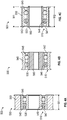
- each of FIG. 4a-4c illustrates a single module sheave unit 500.
- the modular sheave units 500 may each include a bearing 510 that spans a width W1, which is an axial length relative to an axis of rotation for the bearing 510.
- the width W1 may be the same as that of a belt receiving groove 520 of the modular sheave units 500, wherein the belt receiving groove 520 has the same features of the belt receiving groove 211 identified above.
- the bearing 510 may be a ball bearing with an inner race 530, an outer race 540, rolling elements 545, fixing elements 546, and seal rings 547, manufactured from materials that are strong enough for the bearing operation.
- the ball bearing 510 may be, for example, an off-the-shelf product and/or a product having a generalized design that is usable across various elevator sheave configurations and platforms.
- the use of a generic and interchangeable ball bearing 510 may reduce customization requirements as compared with modular sheave units 220 usable for only specific configurations or platforms.
- a radial outer sleeve (outer sleeve) 550 ( FIG. 4a ), which may be an outer annulus, may be placed over the bearing outer race 540.
- the outer sleeve 550 may have the same width W1 as the bearing 510 and may comprise one or more corrosion resistant, energy absorption materials comprising aluminum, plastic, thermoplastic polyurethane (TPU) and rubber.
- TPU thermoplastic polyurethane
- the modular sheave units 500 may be customized without the need for additional surface treatments, such as plating, to the bearing 510.
- a radial inner sleeve (inner sleeve) 560 which may be an inner annulus, may utilized alternatively ( FIG. 4b ) or in addition ( FIG. 4c ) to the outer sleeve 550, and may be placed inside the bearing inner race 530.
- the outer race 540 of the bearing 510 may be formed with the belt receiving groove 520.
- the inner sleeve 560 may comprise the same or different energy absorption material as the outer sleeve 550. Both the outer sleeve 550 and the inner sleeve 560 may be molded or casted to minimize machining.
- the modular sheave 500 units may be individually and inexpensively replaced when damaged, so that it is easier to maintain and reduce repairing costs.
- FIG. 4c Illustrated in FIG. 4c is an embodiment in which the inner sleeve 560 has a width W2 that is larger than the width W1 of the bearing 510 and the outer sleeve 550. This provides for axial spacing between adjacent modular sheave units 500, as further illustrated in FIGS. 5a-5b .
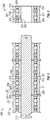
- FIGS. 5a-5b a plurality of the modular sheave units 500 are illustrate in a sheave system 600.
- the sheave system 600 includes a mandrel 610 that may be similar in configuration to the mandrel 210 disclosed above.
- the modular sheave units 500 may be configured against the mandrel 610 similarly to the configuration between the modular sheave units 220 and the mandrel 210 disclosed above.
- set screws 620 or other fastening devices may be on axial ends 630 of the mandrel 610 to secure the modular sheave units 500 against the mandrel 610.
- the modular sheave units 500 may have respective inner sleeves 560 with widths W2 that are larger than the widths W1 for the respective outer sleeves 550 and bearings 510.
- W2 widths
- the inner sleeves 560 of adjacent pairs of the modular shave units 500 are pressed against each other there is a separation between the bearings 510 and the outer sleeves 550.
- This configuration enables relative rotation between adjacent ones of the modular sheave units 500.
- Abrasion resistance paddings may not need to be used between adjacent modular sheave units 500 because the inner sleeves 550 may provide the same function of reducing the occurrence of abrasion between the adjacent modular sheave units 500.
Landscapes
- Engineering & Computer Science (AREA)
- General Engineering & Computer Science (AREA)
- Mechanical Engineering (AREA)
- Civil Engineering (AREA)
- Structural Engineering (AREA)
- Pulleys (AREA)
- Rolling Contact Bearings (AREA)
Abstract
Description
- The disclosure relates generally to sheave assemblies for guiding belts that move elevator cars, and more specifically to modular sheave units of a sheave assembly for an elevator car.
- Commercial elevator systems may use belt sheaves as part of driving system to operate an elevator car. Drive sheaves are used to both drive and guide belts. Idler sheaves may be located intermediate the drive sheave and the elevator car and may be used to maintain proper alignment and tension of belts during operation. Idler sheaves may have belt receiving grooves with a profile contours that constrict sideway motion of belts to ensure alignment. Manufacturing of idler sheaves with contoured outer surfaces may be costly.
- Disclosed is a modular sheave unit comprising: a bearing that includes an outer race, an inner race and one or more rolling elements therebetween; and a sleeve that comprises one or both of: an outer sleeve axially surrounding the outer race, the outer sleeve including an outer surface defining a groove, the groove configured to receive a belt; and an inner sleeve axially surrounded by the inner race and disposed between the inner race and a mandrel.
- In one or more embodiments, the sleeve comprises the outer sleeve; and the inner race includes the inner surface configured to be positioned against a mandrel.
- In one or more embodiments, the sleeve comprises the inner sleeve; and the outer race includes the outer surface that defines the groove.
- In one or more embodiments, the sleeve comprises both the outer sleeve and the inner sleeve.
- In one or more embodiments, the sleeve is formed from one of aluminum, plastic, thermoplastic polyurethane and rubber.
- In one or more embodiments, the sleeve comprises the outer sleeve and the inner sleeve; the outer sleeve is formed from one of aluminum, plastic, thermoplastic polyurethane and rubber; and the inner sleeve is formed from another of aluminum, plastic, thermoplastic polyurethane and rubber.
- In one or more embodiments, the bearing is a ball bearing.
- Further disclosed is an elevator sheave system comprising: a plurality of modular sheave units arranged side by side along a mandrel; and each of the modular sheave units including: a bearing that includes an outer race, an inner race and one or more rolling elements therebetween; and a sleeve that comprises one or both of: an outer sleeve axially surrounding the outer race, the outer sleeve including an outer surface defining a groove, the groove configured to receive a belt; and an inner sleeve axially surrounded by the inner race and disposed between the inner race and a mandrel.
- In one or more embodiments of the elevator sheave system, the sleeve comprises the outer sleeve; the inner race includes the inner surface positioned against a mandrel; and adjacent pairs of the modular sheave units are configured so that axially facing surfaces of the outer sleeve are spaced from one another.
- In one or more embodiments of the elevator sheave system, the sleeve comprises the inner sleeve; the outer race includes the outer surface that defines the groove; and adjacent pairs of the modular sheave units are configured so that axially facing surfaces the inner sleeve are pressed against one another.
- In one or more embodiments of the elevator sheave system, the sleeve comprises the outer sleeve and the inner sleeve; and adjacent pairs of the modular sheave units are configured so that: axially facing surfaces of the inner sleeve are pressed against one another; and axially facing surfaces of the outer sleeve are spaced from one another.
- In one or more embodiments of the elevator sheave system, the sleeve is formed from one of aluminum, plastic, thermoplastic polyurethane and rubber.
- In one or more embodiments of the elevator sheave system, the sleeve comprises the outer sleeve and the inner sleeve; the outer sleeve is formed from one of aluminum, plastic, thermoplastic polyurethane and rubber; and the inner sleeve is formed from another of aluminum, plastic, thermoplastic polyurethane and rubber.
- In one or more embodiments of the elevator sheave system, the bearing is a ball bearing.
- In one or more embodiments, the system further includes fastening devices located on opposing ends of the mandrel to secure the modular sheave units to the mandrel.
- Further disclosed is a method of configuring a modular sheave unit, comprising arranging, a plurality of modular sheave units, side by side along a mandrel, wherein the plurality of the modular sheave units include one or more of the above disclosed features. The method further includes arranging a fastening device on opposing ends of the mandrel to secure the plurality of modular sheave units to the mandrel.
- The following descriptions should not be considered limiting in any way. With reference to the accompanying drawings, like elements are numbered alike:
-
FIG. 1 is a schematic illustration of an elevator system that may employ various embodiments of the present disclosure; -
FIG. 2 is an illustration of an elevator sheave system, configured with modular sheave units, and which may be configured with modular sheave units according to disclosed embodiments; -
FIG. 3 is an illustration of a modular sheave unit of the system ofFIG. 2 ; -
FIGS. 4a-4c illustrate modular sheave units according to disclosed embodiments; and -
FIGS. 5a-5b illustrate an elevator sheave system according to disclosed embodiments. - A detailed description of one or more embodiments of the disclosed apparatus and method are presented herein by way of exemplification and not limitation with reference to the Figures.
-
FIG. 1 is a perspective view of anelevator system 101 including anelevator car 103, acounterweight 105, atension member 107, aguide rail 109, amachine 111, aposition reference system 113, and acontroller 115. Theelevator car 103 andcounterweight 105 are connected to each other by thetension member 107. Thetension member 107 may include or be configured as, for example, ropes, steel cables, and/or coated-steel belts. Thecounterweight 105 is configured to balance a load of theelevator car 103 and is configured to facilitate movement of theelevator car 103 concurrently and in an opposite direction with respect to thecounterweight 105 within anelevator shaft 117 and along theguide rail 109. Thetension member 107 engages themachine 111, which is part of an overhead structure of theelevator system 101. Themachine 111 is configured to control movement between theelevator car 103 and thecounterweight 105. Thecontroller 115 is located, as shown, in acontroller room 121 of theelevator shaft 117 and is configured to control the operation of theelevator system 101, and particularly theelevator car 103, for example, to stop at one ormore landings 125. - In
FIGS. 2 and 3 , anelevator sheave system 200 andmodular sheave units 220 thereof are illustrated, which may employ various features of the disclosed embodiments, and wherein onemodular sheave unit 220 is illustrated inFIG. 3 . Themodular sheave units 220 may each include anouter annulus 201, aninner annulus 202, afixing frame 203, two annular rows ofball bodies 204 andseal rings 205. Theouter annulus 201 is provided with abelt receiving groove 211 on its radial outer surface to support, and guide, a belt. Thebelt receiving groove 211 may have abelt seating portion 311 which may be an axial center portion having an arcuate convex curvature forming a belt seat and opposing flangedside walls 312 for centering and providing transition fit with a belt. This configuration reduces the friction against a belt disposed against thebelt receiving groove 211 and increase a usage life of themodular sheave unit 220. - The two rows of
ball bodies 204 may be respectively seated on axial left (distal) and right (proximate) sides of radial innerball seating grooves 212 of theouter annulus 201 and axial left and right sides of radial outerball seating grooves 221 of theinner annulus 202. Thefixing frame 203 may secure the rows ofball bodies 204 between theouter annulus 201 and theinner annulus 202. As can be appreciated, theouter annulus 201 andinner annulus 202 are configured to be respective outer and inner races of a ball bearing structure formed by thesheave system 200. The axial end faces of theouter annulus 201 and theinner annulus 202 may be provided with radially opposingseal ring grooves 206. Theseal ring 205 may be provided in theseal ring grooves 206 between theouter annulus 201 and theinner annulus 202. - The
sheave system 200 includes amandrel 210 and a plurality of themodular sheave units 220 arranged axially side by side along themandrel 210. Themodular sheave unit 220 and the outer surface of themandrel 210 may form a transition fit. Axial end faces of theinner annulus 202 of axially adjacentmodular sheave units 220 may be axially pressed against each other. Axial end faces of theouter portion 201 of axially adjacentmodular sheave units 220 may be axially spaced from each other to allow relative rotation therebetween.Abrasion resistance paddings 207 may be arranged between the axial end faces of theinner annulus 202 of axially adjacentmodular sheave units 220. This configuration reduces friction between the adjacentmodular sheave units 220 and further increases usage life of themodular sheave units 220. Jump rings may be used on the axial ends of themandrel 210 to secure themodular sheave units 220 to themandrel 210. - Various issues may result with the above disclosed modular sheave units. Manufacturing modular sheave units as disclosed above may result in significant costs. Moving surfaces may need to be plated. If damaged, such units may be difficult to repair and replace.
- Turning now to
FIGS. 4a-4c ,modular sheave units 500 are disclosed according to one or more embodiments, wherein each ofFIG. 4a-4c illustrates a singlemodule sheave unit 500. Themodular sheave units 500 may each include abearing 510 that spans a width W1, which is an axial length relative to an axis of rotation for thebearing 510. The width W1 may be the same as that of abelt receiving groove 520 of themodular sheave units 500, wherein thebelt receiving groove 520 has the same features of thebelt receiving groove 211 identified above. - The
bearing 510 may be a ball bearing with aninner race 530, anouter race 540, rollingelements 545, fixingelements 546, and seal rings 547, manufactured from materials that are strong enough for the bearing operation. Theball bearing 510 may be, for example, an off-the-shelf product and/or a product having a generalized design that is usable across various elevator sheave configurations and platforms. The use of a generic andinterchangeable ball bearing 510 may reduce customization requirements as compared withmodular sheave units 220 usable for only specific configurations or platforms. - A radial outer sleeve (outer sleeve) 550 (
FIG. 4a ), which may be an outer annulus, may be placed over the bearingouter race 540. Theouter sleeve 550 may have the same width W1 as thebearing 510 and may comprise one or more corrosion resistant, energy absorption materials comprising aluminum, plastic, thermoplastic polyurethane (TPU) and rubber. By including anouter sleeve 550 with ageneric ball bearing 510, themodular sheave units 500 may be customized without the need for additional surface treatments, such as plating, to thebearing 510. - A radial inner sleeve (inner sleeve) 560, which may be an inner annulus, may utilized alternatively (
FIG. 4b ) or in addition (FIG. 4c ) to theouter sleeve 550, and may be placed inside the bearinginner race 530. In embodiments with aninner sleeve 560 and without the outer sleeve 550 (FIG. 4b ), theouter race 540 of thebearing 510 may be formed with thebelt receiving groove 520. Theinner sleeve 560 may comprise the same or different energy absorption material as theouter sleeve 550. Both theouter sleeve 550 and theinner sleeve 560 may be molded or casted to minimize machining. Thus, themodular sheave 500 units may be individually and inexpensively replaced when damaged, so that it is easier to maintain and reduce repairing costs. - Illustrated in
FIG. 4c is an embodiment in which theinner sleeve 560 has a width W2 that is larger than the width W1 of thebearing 510 and theouter sleeve 550. This provides for axial spacing between adjacentmodular sheave units 500, as further illustrated inFIGS. 5a-5b . Turning now toFIGS. 5a-5b , a plurality of themodular sheave units 500 are illustrate in asheave system 600. Thesheave system 600 includes amandrel 610 that may be similar in configuration to themandrel 210 disclosed above. Themodular sheave units 500 may be configured against themandrel 610 similarly to the configuration between themodular sheave units 220 and themandrel 210 disclosed above. In addition, setscrews 620 or other fastening devices may be onaxial ends 630 of themandrel 610 to secure themodular sheave units 500 against themandrel 610. As indicated withFIG. 4c , themodular sheave units 500 may have respectiveinner sleeves 560 with widths W2 that are larger than the widths W1 for the respectiveouter sleeves 550 andbearings 510. Thus, when theinner sleeves 560 of adjacent pairs of themodular shave units 500 are pressed against each other there is a separation between thebearings 510 and theouter sleeves 550. This configuration enables relative rotation between adjacent ones of themodular sheave units 500. Abrasion resistance paddings, however, may not need to be used between adjacentmodular sheave units 500 because theinner sleeves 550 may provide the same function of reducing the occurrence of abrasion between the adjacentmodular sheave units 500. - The terminology used herein is for the purpose of describing particular embodiments only and is not intended to be limiting of the present disclosure. As used herein, the singular forms "a", "an" and "the" are intended to include the plural forms as well, unless the context clearly indicates otherwise. It will be further understood that the terms "comprises" and/or "comprising," when used in this specification, specify the presence of stated features, integers, steps, operations, elements, and/or components, but do not preclude the presence or addition of one or more other features, integers, steps, operations, element components, and/or groups thereof.
- While the present disclosure has been described with reference to an exemplary embodiment or embodiments, it will be understood by those skilled in the art that various changes may be made and equivalents may be substituted for elements thereof without departing from the scope of the present disclosure. In addition, many modifications may be made to adapt a particular situation or material to the teachings of the present disclosure without departing from the essential scope thereof. Therefore, it is intended that the present disclosure not be limited to the particular embodiment disclosed as the best mode contemplated for carrying out this present disclosure, but that the present disclosure will include all embodiments falling within the scope of the claims.
Claims (15)
- A modular sheave unit comprising:a bearing that includes an outer race, an inner race and one or more rolling elements therebetween; anda sleeve that comprises one or both of:an outer sleeve axially surrounding the outer race, the outer sleeve including an outer surface defining a groove, the groove configured to receive a belt; andan inner sleeve axially surrounded by the inner race and disposed between the inner race and a mandrel.
- The modular sleeve unit of claim 1, wherein:the sleeve comprises the outer sleeve; andthe inner race includes the inner surface configured to be positioned against a mandrel.
- The modular sheave unit of claim 1 or 2, wherein:the sleeve comprises the inner sleeve; andthe outer race includes the outer surface that defines the groove.
- The modular sheave unit of any preceding claim, wherein the sleeve comprises the outer sleeve and the inner sleeve.
- The modular sheave unit of any preceding claim, wherein the sleeve is formed from one of aluminum, plastic, thermoplastic polyurethane and rubber.
- The modular sheave unit of any preceding claim, wherein:the sleeve comprises the outer sleeve and the inner sleeve;the outer sleeve is formed from one of aluminum, plastic, thermoplastic polyurethane and rubber; andthe inner sleeve is formed from another of aluminum, plastic, thermoplastic polyurethane and rubber.
- The modular sheave unit of any preceding claim, wherein the bearing is a ball bearing.
- An elevator sheave system comprising:
a plurality of modular sheave units according to any preceding claim arranged side by side along a mandrel. - The system of claim 8, wherein:the sleeve comprises the outer sleeve;the inner race includes the inner surface positioned against the mandrel; andadjacent pairs of the modular sheave units are configured so that axially facing surfaces of the outer sleeve are spaced from one another.
- The system of claim 8 or 9, wherein:the sleeve comprises the inner sleeve;the outer race includes the outer surface that defines the groove; andadjacent pairs of the modular sheave units are configured so that axially facing surfaces the inner sleeve are pressed against one another.
- The system of any of claims 8-10, wherein:the sleeve comprises the outer sleeve and the inner sleeve; andadjacent pairs of the modular sheave units are configured so that:axially facing surfaces of the inner sleeve are pressed against one another; andaxially facing surfaces of the outer sleeve are spaced from one another.
- The system of any of claims 8-11, including:
fastening devices located on opposing ends of the mandrel to secure the modular sheave units to the mandrel. - A method of configuring a modular sheave unit, comprising:
arranging, a plurality of modular sheave units, side by side along a mandrel, each of the modular sheave units including:a bearing that includes an outer race, an inner race and one or more rolling elements therebetween; anda sleeve that comprises one or both of:an outer sleeve axially surrounding the outer race, the outer sleeve including an outer surface defining a groove, the groove configured to receive a belt; andan inner sleeve axially surrounded by the inner race and disposed between the inner race and a mandrel. - The method of claim 13, wherein:the sleeve comprises the outer sleeve;the inner race includes the inner surface positioned against a mandrel; andadjacent pairs of the modular sheave units are configured so that axially facing surfaces of the outer sleeve of are spaced from one another;
and/orthe sleeve comprises the inner sleeve;the outer race includes the outer surface that defines the groove; andadjacent pairs of the modular sheave units are configured so that axially facing surfaces of the inner sleeve are pressed against one another;
and/orthe sleeve comprises both the outer sleeve and the inner sleeve; andadjacent pairs of the modular sheave units are arranged so that:axially facing surfaces of the inner sleeve are pressed against one another; andaxially facing surfaces of the outer sleeve are spaced from one another. - The method of claim 13 or 14, comprising:
arranging a fastening device on opposing ends of the mandrel to secure the plurality of modular sheave units to the mandrel.
Applications Claiming Priority (1)
| Application Number | Priority Date | Filing Date | Title |
|---|---|---|---|
| US16/403,216 US11261062B2 (en) | 2019-05-03 | 2019-05-03 | Modular sheave unit |
Publications (1)
| Publication Number | Publication Date |
|---|---|
| EP3733585A1 true EP3733585A1 (en) | 2020-11-04 |
Family
ID=69024200
Family Applications (1)
| Application Number | Title | Priority Date | Filing Date |
|---|---|---|---|
| EP19219665.7A Pending EP3733585A1 (en) | 2019-05-03 | 2019-12-24 | Modular sheave unit |
Country Status (3)
| Country | Link |
|---|---|
| US (1) | US11261062B2 (en) |
| EP (1) | EP3733585A1 (en) |
| CN (1) | CN111874777A (en) |
Families Citing this family (5)
| Publication number | Priority date | Publication date | Assignee | Title |
|---|---|---|---|---|
| US11473989B2 (en) * | 2018-07-31 | 2022-10-18 | Illinois Tool Works Inc. | Multi-dimensional sheave for use in tension measurement systems |
| ES2993504T3 (en) * | 2021-06-28 | 2025-01-02 | Otis Elevator Co | Belt sheave for passenger conveyor systems |
| US11999590B2 (en) | 2022-01-03 | 2024-06-04 | Otis Elevator Company | Modular elevator sheave assembly |
| US12606421B2 (en) | 2022-06-09 | 2026-04-21 | Cable Arm Inc. | Level cut clamshell bucket assembly |
| AT528058A1 (en) * | 2024-03-11 | 2025-09-15 | Faigle Kunststoffe Gmbh | Roller for a traction device |
Citations (4)
| Publication number | Priority date | Publication date | Assignee | Title |
|---|---|---|---|---|
| CN103171946B (en) * | 2013-03-08 | 2015-05-06 | 宁波谷达机电有限公司 | Elevator guiding wheel assembly and adjustment method of same |
| WO2016019135A1 (en) * | 2014-07-31 | 2016-02-04 | Otis Elevator Company | Sheave for elevator system |
| US20170349410A1 (en) * | 2016-06-07 | 2017-12-07 | Xu Ming WEN | Modular Elevator Sheave |
| US20190047826A1 (en) * | 2017-08-08 | 2019-02-14 | Otis Elevator Company | Unitized segmented sheave assembly |
Family Cites Families (26)
| Publication number | Priority date | Publication date | Assignee | Title |
|---|---|---|---|---|
| US2459290A (en) * | 1945-08-30 | 1949-01-18 | Aetna Ball & Roller Bearing Co | Pulley block and bearing assembly |
| US3279762A (en) * | 1964-03-11 | 1966-10-18 | Otis Elevator Co | Noise abating and traction improving elevator sheave |
| DE2862182D1 (en) * | 1978-09-25 | 1983-03-24 | Plumettaz Sa | Suspending apparatus for a facade's maintenance platform |
| US6896415B2 (en) | 2001-07-10 | 2005-05-24 | Nsk, Ltd. | Rolling bearing and bearing apparatus |
| JP2008215564A (en) | 2007-03-07 | 2008-09-18 | Jtekt Corp | Resin wound parts |
| CN101126424A (en) | 2007-09-26 | 2008-02-20 | 洛阳轴研科技股份有限公司 | A slanted roller clutch combined pulley |
| FR2923281B1 (en) | 2007-11-06 | 2010-04-09 | Skf Ab | ROLLER OR ROLLER DEVICE |
| JP2009174588A (en) | 2008-01-22 | 2009-08-06 | Ntn Corp | Bearing with resin pulley |
| US20110114908A1 (en) | 2008-07-03 | 2011-05-19 | Fargo Richard N | Wear and corrosion resistant coating having a roughened surface |
| JP5396060B2 (en) | 2008-10-22 | 2014-01-22 | 日本オーチス・エレベータ株式会社 | Rotating body unit preload setting device and rotating body unit preload setting method |
| WO2010113195A1 (en) | 2009-04-03 | 2010-10-07 | Aktiebolaget Skf | An idler and bearing assembly and a method of manufacturing same |
| CN201961925U (en) | 2011-01-21 | 2011-09-07 | 苏州海仑士科技有限公司 | Steel wire rope pulley |
| EP2687737A1 (en) | 2012-07-20 | 2014-01-22 | Aktiebolaget SKF | Roller unit with bearing and a mounting means and method for manufacturing the same |
| CN203308892U (en) | 2013-05-06 | 2013-11-27 | 北汽福田汽车股份有限公司 | Multi-pulley assembly |
| US9416863B2 (en) | 2013-05-29 | 2016-08-16 | Schaeffler Technologies AG & Co. KG | Pulley ring |
| FR3018886B1 (en) | 2014-03-19 | 2016-03-11 | Skf Ab | ROLLER OR ROLLER DEVICE |
| WO2016096718A1 (en) | 2014-12-18 | 2016-06-23 | Inventio Ag | Electrical energy generation within an elevator installation |
| CN204512360U (en) | 2014-12-25 | 2015-07-29 | 舍弗勒技术有限两合公司 | Isolator belt pulley |
| EP3056461B1 (en) | 2015-02-12 | 2017-09-06 | Kone Corporation | Arrangement and elevator |
| JP2017032096A (en) | 2015-08-04 | 2017-02-09 | Ntn株式会社 | Resin pulley |
| CN205937733U (en) | 2016-08-10 | 2017-02-08 | 莱顿汽车部件(苏州)有限公司 | Pilled -in selvedge timing belt idler |
| CN205956205U (en) * | 2016-08-30 | 2017-02-15 | 龙工(上海)叉车有限公司 | Pulley with bearing |
| CN106744440A (en) | 2016-11-30 | 2017-05-31 | 常州市双强机械制造有限公司 | Tackle-block device |
| EP3470359B1 (en) * | 2017-10-11 | 2021-08-18 | KONE Corporation | Rope wheel assembly, compensator and elevator arrangement |
| CN207500438U (en) | 2017-10-30 | 2018-06-15 | 浙江五洲新春集团股份有限公司 | A kind of improvement steel band of model rope wheel component having unit structure |
| US11059699B2 (en) * | 2018-02-28 | 2021-07-13 | Tk Elevator Innovation And Operations Gmbh | Elevator sheave assembly |
-
2019
- 2019-05-03 US US16/403,216 patent/US11261062B2/en active Active
- 2019-12-24 EP EP19219665.7A patent/EP3733585A1/en active Pending
- 2019-12-31 CN CN201911408209.0A patent/CN111874777A/en active Pending
Patent Citations (4)
| Publication number | Priority date | Publication date | Assignee | Title |
|---|---|---|---|---|
| CN103171946B (en) * | 2013-03-08 | 2015-05-06 | 宁波谷达机电有限公司 | Elevator guiding wheel assembly and adjustment method of same |
| WO2016019135A1 (en) * | 2014-07-31 | 2016-02-04 | Otis Elevator Company | Sheave for elevator system |
| US20170349410A1 (en) * | 2016-06-07 | 2017-12-07 | Xu Ming WEN | Modular Elevator Sheave |
| US20190047826A1 (en) * | 2017-08-08 | 2019-02-14 | Otis Elevator Company | Unitized segmented sheave assembly |
Also Published As
| Publication number | Publication date |
|---|---|
| US20200346899A1 (en) | 2020-11-05 |
| CN111874777A (en) | 2020-11-03 |
| US11261062B2 (en) | 2022-03-01 |
Similar Documents
| Publication | Publication Date | Title |
|---|---|---|
| US11261062B2 (en) | Modular sheave unit | |
| EP1591403B1 (en) | Traction elevator system having multiple machines | |
| US10773929B2 (en) | Sheave for elevator system | |
| US20080223665A1 (en) | Flexible load-bearing member for elevator system | |
| US11059699B2 (en) | Elevator sheave assembly | |
| US12180040B2 (en) | Belt with layered load bearing elements | |
| CN100537395C (en) | Belt drive assembly and method for a passenger conveyor | |
| CA2896146C (en) | Conveyor system for the transport of passengers/goods | |
| US10968080B2 (en) | Drive belt for people conveyors | |
| EP4206108B1 (en) | Modular elevator sheave assembly comprising a plurality of polymer rings | |
| EP1492722B1 (en) | Escalator chain drive mechanism | |
| CN110891890A (en) | Guide wheels in traction tool drives | |
| EP2406167B1 (en) | Modular chain newel with standard bearing | |
| US10435276B2 (en) | Chain link for a highly resilient conveyor chain of a moving walkway, an escalator or a lift | |
| KR102729976B1 (en) | Pully for elevator and elevator system having the same | |
| JP2008156080A (en) | Passenger conveyor | |
| HK1087088B (en) | A passenger conveyor system and a method of moving its step chain along a chain loop | |
| HK1087088A1 (en) | A passenger conveyor system and a method of moving its step chain along a chain loop |
Legal Events
| Date | Code | Title | Description |
|---|---|---|---|
| PUAI | Public reference made under article 153(3) epc to a published international application that has entered the european phase |
Free format text: ORIGINAL CODE: 0009012 |
|
| STAA | Information on the status of an ep patent application or granted ep patent |
Free format text: STATUS: THE APPLICATION HAS BEEN PUBLISHED |
|
| AK | Designated contracting states |
Kind code of ref document: A1 Designated state(s): AL AT BE BG CH CY CZ DE DK EE ES FI FR GB GR HR HU IE IS IT LI LT LU LV MC MK MT NL NO PL PT RO RS SE SI SK SM TR |
|
| AX | Request for extension of the european patent |
Extension state: BA ME |
|
| STAA | Information on the status of an ep patent application or granted ep patent |
Free format text: STATUS: REQUEST FOR EXAMINATION WAS MADE |
|
| 17P | Request for examination filed |
Effective date: 20210504 |
|
| RBV | Designated contracting states (corrected) |
Designated state(s): AL AT BE BG CH CY CZ DE DK EE ES FI FR GB GR HR HU IE IS IT LI LT LU LV MC MK MT NL NO PL PT RO RS SE SI SK SM TR |
|
| STAA | Information on the status of an ep patent application or granted ep patent |
Free format text: STATUS: EXAMINATION IS IN PROGRESS |
|
| 17Q | First examination report despatched |
Effective date: 20221213 |