EP3733523B1 - Method and apparatus for aircraft anti-icing - Google Patents
Method and apparatus for aircraft anti-icing Download PDFInfo
- Publication number
- EP3733523B1 EP3733523B1 EP19216738.5A EP19216738A EP3733523B1 EP 3733523 B1 EP3733523 B1 EP 3733523B1 EP 19216738 A EP19216738 A EP 19216738A EP 3733523 B1 EP3733523 B1 EP 3733523B1
- Authority
- EP
- European Patent Office
- Prior art keywords
- nozzle
- eductor
- hot gas
- shroud
- flow
- Prior art date
- Legal status (The legal status is an assumption and is not a legal conclusion. Google has not performed a legal analysis and makes no representation as to the accuracy of the status listed.)
- Active
Links
Images


Classifications
-
- B—PERFORMING OPERATIONS; TRANSPORTING
- B64—AIRCRAFT; AVIATION; COSMONAUTICS
- B64D—EQUIPMENT FOR FITTING IN OR TO AIRCRAFT; FLIGHT SUITS; PARACHUTES; ARRANGEMENT OR MOUNTING OF POWER PLANTS OR PROPULSION TRANSMISSIONS IN AIRCRAFT
- B64D15/00—De-icing or preventing icing on exterior surfaces of aircraft
- B64D15/02—De-icing or preventing icing on exterior surfaces of aircraft by ducted hot gas or liquid
- B64D15/04—Hot gas application
-
- B—PERFORMING OPERATIONS; TRANSPORTING
- B64—AIRCRAFT; AVIATION; COSMONAUTICS
- B64D—EQUIPMENT FOR FITTING IN OR TO AIRCRAFT; FLIGHT SUITS; PARACHUTES; ARRANGEMENT OR MOUNTING OF POWER PLANTS OR PROPULSION TRANSMISSIONS IN AIRCRAFT
- B64D29/00—Power-plant nacelles, fairings or cowlings
-
- F—MECHANICAL ENGINEERING; LIGHTING; HEATING; WEAPONS; BLASTING
- F02—COMBUSTION ENGINES; HOT-GAS OR COMBUSTION-PRODUCT ENGINE PLANTS
- F02C—GAS-TURBINE PLANTS; AIR INTAKES FOR JET-PROPULSION PLANTS; CONTROLLING FUEL SUPPLY IN AIR-BREATHING JET-PROPULSION PLANTS
- F02C7/00—Features, components parts, details or accessories, not provided for in, or of interest apart form groups F02C1/00 - F02C6/00; Air intakes for jet-propulsion plants
- F02C7/04—Air intakes for gas-turbine plants or jet-propulsion plants
- F02C7/047—Heating to prevent icing
-
- B—PERFORMING OPERATIONS; TRANSPORTING
- B64—AIRCRAFT; AVIATION; COSMONAUTICS
- B64D—EQUIPMENT FOR FITTING IN OR TO AIRCRAFT; FLIGHT SUITS; PARACHUTES; ARRANGEMENT OR MOUNTING OF POWER PLANTS OR PROPULSION TRANSMISSIONS IN AIRCRAFT
- B64D33/00—Arrangement in aircraft of power plant parts or auxiliaries not otherwise provided for
- B64D33/02—Arrangement in aircraft of power plant parts or auxiliaries not otherwise provided for of combustion air intakes
- B64D2033/0233—Arrangement in aircraft of power plant parts or auxiliaries not otherwise provided for of combustion air intakes comprising de-icing means
-
- B—PERFORMING OPERATIONS; TRANSPORTING
- B64—AIRCRAFT; AVIATION; COSMONAUTICS
- B64D—EQUIPMENT FOR FITTING IN OR TO AIRCRAFT; FLIGHT SUITS; PARACHUTES; ARRANGEMENT OR MOUNTING OF POWER PLANTS OR PROPULSION TRANSMISSIONS IN AIRCRAFT
- B64D33/00—Arrangement in aircraft of power plant parts or auxiliaries not otherwise provided for
- B64D33/02—Arrangement in aircraft of power plant parts or auxiliaries not otherwise provided for of combustion air intakes
- B64D2033/0266—Arrangement in aircraft of power plant parts or auxiliaries not otherwise provided for of combustion air intakes specially adapted for particular type of power plants
- B64D2033/0286—Arrangement in aircraft of power plant parts or auxiliaries not otherwise provided for of combustion air intakes specially adapted for particular type of power plants for turbofan engines
Definitions
- the present disclosure relates to anti-icing systems for aircraft jet engine propulsion systems, and more particularly to nozzles for anti-icing systems.
- Typical anti-ice techniques include the ducting of hot gases into a housing adjacent to the likely icing area.
- Current techniques to solve this problem generally fall into one of two types of systems: Impingement style ring systems or swirl nozzle systems.
- the hot gas conduits simply dump hot gases into a housing, such as the leading edge of a jet engine housing or a wing leading edge. While often useful, these systems may not be fully effective due to the low quantity of hot gases introduced relative to the mass of air in the housing, the heating effect tending to be limited to the region near the hot gas introduction point, and the complexity of the hot gas duct system.
- WO 2015/059489 A1 discloses a prior art apparatus for aircraft anti-icing as set forth in the preamble of claim 1.
- US 2013/327012 A1 discloses a prior art gas turbine anti-icing system.
- any reference to attached, fixed, connected or the like may include permanent, removable, temporary, partial, full and/or any other possible attachment option. Additionally, any reference to without contact (or similar phrases) may also include reduced contact or minimal contact. Surface shading and/or crosshatching lines may be used throughout the figures to denote different parts, but not necessarily to denote the same or different materials.
- An anti-icing system of the present disclosure may provide an improved swirling rotational anti-icing system for a leading edge housing, such as the nose cowl of a transport aircraft jet engine, which enhances the mixing of injected hot, high pressure gas with the larger mass of air within the leading edge housing.
- An anti-icing system of the present disclosure may further improve the mixing of hot, high pressure gas with the mass of air within the leading edge housing and thereby materially reduce any tendency for the injection of such hot, high pressure gas to create an area of elevated temperature in the leading edge housing at a position downstream of the injection of such hot gas under severe operating condition.
- Various embodiments of the present disclosure may enhance the circumference uniformity of nose lip temperature and nose lip heat rejection to improve the anti-icing efficiency and to prevent ice accumulation on the exterior of the nose lip upstream of the point of hot gas injection.
- FIG.1 there is seen a schematic representation of a jet turbine engine 10 of the type suitable for aircraft propulsion.
- the turbine engine 10 is housed within a central housing 12. Air enters the engine 10 through an air inlet section 20, between the spinner 16 of the engine and the nose lip or annular single skin housing 14 which constitutes the forward most section of the air inlet 20 of the engine nacelle, though it is noted that certain components have been omitted from the figure for simplicity.
- Engine thrust is produced by mixing incoming air and fuel to form a combustible mixture within the central housing 12 and passing the hot, high pressure exhaust gases through exhaust outlet 22 and out the rear of the engine.
- ice may tend to form on the nose lip 14 (in addition to other leading edge housing aircraft components omitted for simplicity).
- the ice changes the geometry of the inlet area 18 between the nose lip 14 and the spinner 16, adversely affecting the quantity, flow path and quality of incoming air.
- pieces of ice may periodically break free from these components and enter the engine, damaging rotor blades and other internal engine components.
- the hot region is the environmental bleed air manifold although in various embodiments the hot region may be any other hot air source such as the compressor discharge bleed air manifold.
- the other end 30 penetrates a bulkhead 32 that substantially closes the nose lip 14 to form the D-duct to enclose a quantity of air with the annular space created by such bulkhead 32 and the nose lip 14.
- the conduit 26 carrying the hot, high pressure gas from the compressor section of a jet engine 10 extends through the bulkhead 32 that closes off the annular nose lip 14 of the inlet 18 to create an annular chamber filled with air.
- the conduit 26 has an outlet nozzle 34 connected to its outlet end. The outlet nozzle 34 directs the hot gas around the circumference of the annular chamber.
- Outlet nozzle 34 may be made from a metallic material suitable to withstand high temperature gasses, for example from compressor section 24 of the jet engine 10.
- outlet nozzle 34 may comprise one of a steel, a stainless steel, a tungsten carbide, a titanium, a titanium alloy, a nickel, nickel alloy, a nickel steel (e.g., an austenitic nickel-chromium-based alloy such as that available under the trade name INCONEL), or any other material suitable to withstand high temperature gasses from compressor section 24.
- outlet nozzle 34 is additively manufactured.
- additive manufacturing encompasses any method or process whereby a three-dimensional object is produced by creation of a substrate or material to an object, such as by addition of successive layers of a material to an object to produce a manufactured product having an increased mass or bulk at the end of the additive manufacturing process than the beginning of the process.
- traditional manufacturing e.g., forms of subtractive manufacturing
- material removal or subtractive processes such as cutting, lathing, drilling, grinding, and/or the like, to produce a final manufactured object that has a decreased mass or bulk relative to the starting workpiece.
- additive manufacturing should not be construed to encompass fabrication or joining of previously formed objects.
- outlet nozzle 34 is a monolithic structure, in accordance with various embodiments. In various embodiments, outlet nozzle 34 is a combination of monolithic sub-structures that are joined together, for example via welding, fasteners, or a threaded connection, among others.
- outlet nozzle 34 may turn the flow of hot gas substantially 90 degrees so that the outlet of outlet nozzle 34 directs the flow of hot gas approximately tangent to the centerline of the annular nose lip 14. In various embodiments, the outlet of outlet nozzle 34 directs the flow of hot gas in a direction more or less than tangent to the centerline of the annular nose lip 14.
- a suitable exhaust means shown as suitably sized holes 36 formed in an outboard position of the nose lip 14, permit a portion of such entrained air to escape the nose lip 14 equal to the mass flow rate of hot gas being injected into the nose lip 14 to maintain an equilibrium of flow.
- holes 36 may be located in other areas including but not limited to the rear of housing 14.
- the conduit 30 carries hot, high pressure gas from the jet engine 10 to a leading edge housing of other aircraft components, such as a wing for example.
- outlet nozzle 34 may be used for anti-ice systems associated with other aircraft components without departing from the scope of the present disclosure.
- Outlet nozzle 34 may be configured to increase a speed of the hot gas exiting the outlet nozzle 34.
- outlet nozzle 34 is illustrated in accordance with various embodiments.
- an anti-ice nozzle may include outlet nozzle 34 which may be configured to receive heated gases from a compression stage of an engine nacelle and further configured to conduct the gases to an internal volume of a leading edge housing mounted to the leading edge of the engine nacelle.
- outlet nozzle 34 conducts the hot gas based on a flow pattern, wherein the flow pattern is determined based, at least in part, on a geometry of the outlet nozzle 34, as described herein.
- outlet nozzle 34 comprises a nozzle body 50 comprising an inlet 40 whereby the hot gas enters nozzle body 50 and one or more nozzles, such as first nozzle 52, second nozzle 54, and third nozzle 56, whereby the hot gas exits nozzle body 50.
- outlet nozzle 34 may comprise a collar 42 whereby nozzle body 50 is secured to bulkhead 32.
- collar 42 may include one or more holes, such as hole 43, which match holes in an internal bulkhead of the leading edge housing, and one or more fasteners, such as nuts and bolts, may be used to fasten collar 42, as well as nozzle body 50, to the internal bulkhead.
- the holes and fasteners may control or determine the positional tolerances of nozzles, such as nozzle body 50, that may be included in the leading edge housing.
- the inlet 40 may comprise one or more flanges, such as first flange 44, configured to couple nozzle body 50 to a source of the gases.
- first flange 44 may be configured to be coupled to a pipe, tube, or conduit (e.g., conduit 30 of FIG. 3 ) that may be included in a manifold system coupled to a compression stage of the engine.
- a second flange 46 may be configured to provide further coupling with the pipe or conduit and/or may provide additional structural support for the coupling or connection between nozzle body 50 and the manifold system coupled to the compression stage. Furthermore, second flange 46 may provide structural support for coupling nozzle body 50 to bulkhead 32.
- first nozzle 52, second nozzle 54, and third nozzle 56 may be oriented such that the direction of flows generated by first nozzle 52, second nozzle 54, and third nozzle 56 are substantially parallel to the internal bulkhead that may be attached to collar 42.
- the orientation of the nozzles may form about a 90 degree angle with a centerline of the nozzle body 50.
- the centerline axes of first nozzle 52, second nozzle 54, and/or third nozzle 56 may be orthogonal with respect to the centerline axis of nozzle body 50.
- first nozzle 52 may be included in a first portion of nozzle body 50 and may be a flanged opening that provides a first flow path through which a first portion of gases received from the manifold system associated with the compression stage may be released into the internal volume of the leading edge housing of the engine nacelle.
- second nozzle 54 may be included in a second portion of nozzle body 50 and may be a flanged opening that provides a second flow path through which a second portion of gases received from the manifold system associated with the compression stage may be released into the internal volume of the leading edge housing of the engine nacelle.
- Third nozzle 56 may similarly be included in a third portion of nozzle body 50.
- First nozzle 52 may comprise an annular flange extending from nozzle body 50, in accordance with various embodiments.
- outlet nozzle 534 is illustrated, in accordance with various embodiments.
- outlet nozzle 534 is similar to outlet nozzle 34 of FIG. 4 , except that outlet nozzle 34 further includes one or more eductor shrouds, such as eductor shroud 562, eductor shroud 564, and eductor shroud 566, configured to entrain a secondary lower pressure ambient air 502 using the pressure energy found within the hot, high pressure gas 570.
- eductor shrouds such as eductor shroud 562, eductor shroud 564, and eductor shroud 566, configured to entrain a secondary lower pressure ambient air 502 using the pressure energy found within the hot, high pressure gas 570.
- eductor shroud 562 may be disposed concentrically with respect to nozzle 552.
- Eductor shroud 562 may at least partially surround nozzle 552.
- Eductor shroud 562 may completely surround nozzle 552.
- Eductor shroud 562 may be supported, for example via a structural support 553, by nozzle 552.
- eductor shrouds of the present disclosure may be supported by a nozzle body (see FIG. 6A ) or a collar (see FIG. 7 ).
- Eductor shroud 562 may comprise a truncated conical geometry. Eductor shroud 562 may comprise an inlet aperture 571 at a first end thereof. Eductor shroud 562 may comprise an exit aperture 572 at a second, opposite end thereof. In various embodiments, the cross-sectional area of inlet aperture 571 is greater than the cross-sectional area of outlet aperture 572. In this manner, ambient air 502 may be focused towards the high pressure gas 570 exiting nozzle 552. In this manner, ambient air 502 may be accelerated towards the high pressure gas 570 exiting nozzle 552. In this regard, eductor shroud 562 may be tapered towards outlet aperture 572.
- the cross-sectional area of outlet aperture 572 is greater than the cross-sectional area of exit 555 of nozzle 552.
- the exit plane of outlet aperture 572 is located downstream from the exit plane of the exit 555 of nozzle 552. In this manner, high pressure gas 570 may entrain the flow of ambient air 502 through eductor shroud 562.
- Outlet aperture 572 may comprises a circular geometry, an ovular geometry, a corrugated geometry, a polygonal geometry, or any other suitable geometry.
- Exit 555 may comprises a circular geometry, an ovular geometry, a corrugated geometry (see FIG. 7 ), a polygonal geometry, or any other suitable geometry.
- each nozzle 552, 554, 556 may be oriented at a non-orthogonal angle with respect to the longitudinal axis 590 of nozzle body 550.
- the centerline axis 591 of nozzle 552 may be oriented at a non-orthogonal angle ⁇ with respect to longitudinal axis 590 of nozzle body 550.
- angle ⁇ is between one and fifty degrees (1°-50°). In various embodiments, angle ⁇ is between five and forty-five degrees (5°-45°).
- each nozzle 552, 554, 556 may be oriented at an angle with respect to any of the other nozzles 552, 554, 556.
- nozzle 556 may be rotated about the longitudinal axis 590 of nozzle body 550 such that the centerline axis 593 of nozzle 556 is oriented at an angle ⁇ with respect to centerline axis 591 of nozzle 552 (represented by dashed line 591').
- angle ⁇ is between one and ninety degrees (1°-90°).
- angle ⁇ is between five and forty-five degrees (5°-45°).
- angle ⁇ is between five and thirty degrees (5°-30°).
- hot spots on the inlet lip may be reduced in response to orientating one or more individual nozzles 552, 554, 556.
- mixing efficiency may be increased in response to orientating one or more individual nozzles 552, 554, 556.
- the eductor geometry or design of outlet nozzle 534 provides enhanced and efficient mixing of the flow stream emitted by outlet nozzle 534 with the gases included in the internal volume of the annular chamber defined between the bulkhead 32 and the annular nose lip 14. In this way, the flow pattern generated by the eductor geometry of outlet nozzle 534 may minimize the temperature of the hot spot associated with the annular nose lip 14 that includes outlet nozzle 534.
- outlet nozzle 634 is illustrated, in accordance with various embodiments.
- outlet nozzle 634 is similar to outlet nozzle 534 of FIG. 5A , except that the eductor shrouds 660, such as eductor shroud 662, eductor shroud 664, and eductor shroud 666, are supported by nozzle body 650.
- eductor shroud 662, eductor shroud 664, and eductor shroud 666 may extend from nozzle body 650.
- each eductor shroud may intersect with an adjacent eductor shroud, in accordance with various embodiments.
- eductor shroud 664 may intersect with eductor shroud 652 at a first side 691 thereof, and eductor shroud 664 may intersect with eductor shroud 656 at a second, opposite side 692 thereof.
- outlet nozzle 734 is illustrated, in accordance with various embodiments.
- outlet nozzle 734 is similar to outlet nozzle 34 of FIG. 4 and/or outlet nozzle 534 of FIG. 5A , except that the outlet nozzle 734 includes a single eductor shroud 762 configured to entrain a secondary lower pressure ambient air 702 using the pressure energy found within the hot, high pressure gas 770, and direct the entrained ambient air 702 towards a plurality of nozzles, such as nozzle 752, nozzle 754, and nozzle 756.
- eductor shroud 762 extends from collar 742. Eductor shroud 762 may comprise an inlet aperture 771 and an outlet aperture 772.
- inlet aperture 771 comprises a high aspect ratio. In various embodiments, inlet aperture 771 comprises an aspect ratio of greater than 2. In various embodiments, inlet aperture 771 comprises an aspect ratio of greater than 3. In various embodiments, outlet aperture 772 comprises a high aspect ratio. In various embodiments, outlet aperture 772 comprises an aspect ratio of greater than 2. In various embodiments, outlet aperture 772 comprises an aspect ratio of greater than 3.
- references to "various embodiments”, “one embodiment”, “an embodiment”, “an example embodiment”, etc. indicate that the embodiment described may include a particular feature, structure, or characteristic, but every embodiment may not necessarily include the particular feature, structure, or characteristic. Moreover, such phrases are not necessarily referring to the same embodiment. Further, when a particular feature, structure, or characteristic is described in connection with an embodiment, it is submitted that it is within the knowledge of one skilled in the art to affect such feature, structure, or characteristic in connection with other embodiments whether or not explicitly described. After reading the description, it will be apparent to one skilled in the relevant art(s) how to implement the disclosure in alternative embodiments.
Landscapes
- Engineering & Computer Science (AREA)
- Aviation & Aerospace Engineering (AREA)
- Chemical & Material Sciences (AREA)
- Combustion & Propulsion (AREA)
- Mechanical Engineering (AREA)
- General Engineering & Computer Science (AREA)
- Jet Pumps And Other Pumps (AREA)
Description
- The present disclosure relates to anti-icing systems for aircraft jet engine propulsion systems, and more particularly to nozzles for anti-icing systems.
- The formation of ice on aircraft wings, propellers, air inlets of engines, etc. adds considerable weight, and changes the airfoil or inlet configuration, which may make the aircraft more difficult to fly and in some cases has caused loss of aircraft. In the case of jet aircraft, large pieces of ice breaking loose from the leading edge of an engine inlet housing can damage rotating turbine blades or other internal engine components and cause engine failure.
- Typical anti-ice techniques include the ducting of hot gases into a housing adjacent to the likely icing area. Current techniques to solve this problem generally fall into one of two types of systems: Impingement style ring systems or swirl nozzle systems. In each case, the hot gas conduits simply dump hot gases into a housing, such as the leading edge of a jet engine housing or a wing leading edge. While often useful, these systems may not be fully effective due to the low quantity of hot gases introduced relative to the mass of air in the housing, the heating effect tending to be limited to the region near the hot gas introduction point, and the complexity of the hot gas duct system.
-
WO 2015/059489 A1 discloses a prior art apparatus for aircraft anti-icing as set forth in the preamble of claim 1. -
US 4 688 745 A discloses a prior art swirl anti-ice system. -
US 2013/327012 A1 discloses a prior art gas turbine anti-icing system. - From a first aspect, there is provided an apparatus for aircraft anti-icing as recited in claim 1.
- There is also provided a method for preventing formation of ice as recited in
claim 14. - Features of embodiments of the invention are set forth in the dependent claims.
- The foregoing features, elements, steps, or methods may be combined in various combinations without exclusivity, unless expressly indicated herein otherwise. These features, elements, steps, or methods as well as the operation of the disclosed embodiments will become more apparent in light of the following description and accompanying drawings.
- The subject matter of the present disclosure is as defined by the appended claims. A more complete understanding of the present disclosure, however, may best be obtained by referring to the detailed description and claims when considered in connection with the drawing figures, wherein like numerals denote like elements.
-
FIG. 1 illustrates a schematic representation of a typical jet turbine engine, in accordance with various embodiments. -
FIG. 2 illustrates a schematic view of a jet engine inlet, in accordance with various embodiments. -
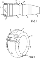
FIG. 3 illustrates a perspective view, partially in section, of an outlet nozzle installed in a leading edge housing, in accordance with various embodiments. -
FIG. 4 illustrates a perspective view of an outlet nozzle having a plurality of nozzles extending from a nozzle body, with an eductor shroud omitted for clarity, in accordance with various embodiments. -
FIG. 5A illustrates a perspective view of an outlet nozzle having a plurality of nozzles extending from a nozzle body and having a plurality of eductor shrouds associated with each nozzle, in accordance with various embodiments. -
FIG. 5B illustrates a perspective view of an outlet nozzle having a plurality of nozzles extending from a nozzle body and having a plurality of eductor shrouds associated with each nozzle, wherein each nozzle may be angled, in accordance with various embodiments. -
FIG. 6A and FIG. 6B illustrate a perspective view and a section view, respectively, of an outlet nozzle having a plurality of nozzles extending from a nozzle body and having a plurality of eductor shrouds associated with each nozzle, in accordance with various embodiments. -
FIG. 7 illustrates a perspective view of an outlet nozzle having a plurality of nozzles extending from a nozzle body and having a single eductor shroud for the plurality of nozzles, in accordance with various embodiments. - The detailed description of exemplary embodiments herein makes reference to the accompanying drawings, which show exemplary embodiments by way of illustration. While these exemplary embodiments are described in sufficient detail to enable those skilled in the art to practice the inventions, it should be understood that other embodiments may be realized and that logical changes and adaptations in design and construction may be made in accordance with this invention and the teachings herein. Thus, the detailed description herein is presented for purposes of illustration only and not of limitation. The scope of the invention is defined by the appended claims. For example, the steps recited in any of the method or process descriptions may be executed in any order and are not necessarily limited to the order presented. Furthermore, any reference to singular includes plural embodiments, and any reference to more than one component or step may include a singular embodiment or step. Also, any reference to attached, fixed, connected or the like may include permanent, removable, temporary, partial, full and/or any other possible attachment option. Additionally, any reference to without contact (or similar phrases) may also include reduced contact or minimal contact. Surface shading and/or crosshatching lines may be used throughout the figures to denote different parts, but not necessarily to denote the same or different materials.
- An anti-icing system of the present disclosure may provide an improved swirling rotational anti-icing system for a leading edge housing, such as the nose cowl of a transport aircraft jet engine, which enhances the mixing of injected hot, high pressure gas with the larger mass of air within the leading edge housing. An anti-icing system of the present disclosure may further improve the mixing of hot, high pressure gas with the mass of air within the leading edge housing and thereby materially reduce any tendency for the injection of such hot, high pressure gas to create an area of elevated temperature in the leading edge housing at a position downstream of the injection of such hot gas under severe operating condition.
- Various embodiments of the present disclosure may enhance the circumference uniformity of nose lip temperature and nose lip heat rejection to improve the anti-icing efficiency and to prevent ice accumulation on the exterior of the nose lip upstream of the point of hot gas injection.
- With reference to
FIG.1 , there is seen a schematic representation of ajet turbine engine 10 of the type suitable for aircraft propulsion. Theturbine engine 10 is housed within acentral housing 12. Air enters theengine 10 through anair inlet section 20, between thespinner 16 of the engine and the nose lip or annularsingle skin housing 14 which constitutes the forward most section of theair inlet 20 of the engine nacelle, though it is noted that certain components have been omitted from the figure for simplicity. Engine thrust is produced by mixing incoming air and fuel to form a combustible mixture within thecentral housing 12 and passing the hot, high pressure exhaust gases through exhaust outlet 22 and out the rear of the engine. - In flight, ice may tend to form on the nose lip 14 (in addition to other leading edge housing aircraft components omitted for simplicity). The ice changes the geometry of the
inlet area 18 between thenose lip 14 and thespinner 16, adversely affecting the quantity, flow path and quality of incoming air. Also, pieces of ice may periodically break free from these components and enter the engine, damaging rotor blades and other internal engine components. - With combined reference to
FIG. 1, FIG. 2 , andFIG. 3 , within thecompressor section 24 of thejet engine 10 there is a region containing hot gases. Asuitable conduit 26 or tube is connected at afirst end 28 to that hot region. In various embodiments, the hot region is the environmental bleed air manifold although in various embodiments the hot region may be any other hot air source such as the compressor discharge bleed air manifold. Theother end 30 penetrates abulkhead 32 that substantially closes thenose lip 14 to form the D-duct to enclose a quantity of air with the annular space created bysuch bulkhead 32 and thenose lip 14. - The
conduit 26 carrying the hot, high pressure gas from the compressor section of ajet engine 10 extends through thebulkhead 32 that closes off theannular nose lip 14 of theinlet 18 to create an annular chamber filled with air. Theconduit 26 has anoutlet nozzle 34 connected to its outlet end. Theoutlet nozzle 34 directs the hot gas around the circumference of the annular chamber. -
Outlet nozzle 34 may be made from a metallic material suitable to withstand high temperature gasses, for example fromcompressor section 24 of thejet engine 10. In various embodiments,outlet nozzle 34 may comprise one of a steel, a stainless steel, a tungsten carbide, a titanium, a titanium alloy, a nickel, nickel alloy, a nickel steel (e.g., an austenitic nickel-chromium-based alloy such as that available under the trade name INCONEL), or any other material suitable to withstand high temperature gasses fromcompressor section 24. - In various embodiments,
outlet nozzle 34 is additively manufactured. As used herein, the term "additive manufacturing" encompasses any method or process whereby a three-dimensional object is produced by creation of a substrate or material to an object, such as by addition of successive layers of a material to an object to produce a manufactured product having an increased mass or bulk at the end of the additive manufacturing process than the beginning of the process. In contrast, traditional manufacturing (e.g., forms of subtractive manufacturing) by machining or tooling typically relies on material removal or subtractive processes, such as cutting, lathing, drilling, grinding, and/or the like, to produce a final manufactured object that has a decreased mass or bulk relative to the starting workpiece. Other traditional manufacturing methods includes forging or casting, such as investment casting, which utilizes the steps of creating a form, making a mold of the form, and casting or forging a material (such as metal) using the mold. As used herein, the term "additive manufacturing" should not be construed to encompass fabrication or joining of previously formed objects. - A variety of additive manufacturing technologies are commercially available. Such technologies include, for example, fused deposition modeling, polyjet 3D printing, electron beam freeform fabrication, direct metal laser sintering, electron-beam melting, selective laser melting, selective heat sintering, selective laser sintering, stereolithography, multiphoton photopolymerization, and digital light processing. These technologies may use a variety of materials as substrates for an additive manufacturing process, including various plastics and polymers, metals and metal alloys, ceramic materials, metal clays, organic materials, and the like. Any method of additive manufacturing and associated compatible materials, whether presently available or yet to be developed, are intended to be included within the scope of the present disclosure. In this regard,
outlet nozzle 34 is a monolithic structure, in accordance with various embodiments. In various embodiments,outlet nozzle 34 is a combination of monolithic sub-structures that are joined together, for example via welding, fasteners, or a threaded connection, among others. - In operation,
outlet nozzle 34 may turn the flow of hot gas substantially 90 degrees so that the outlet ofoutlet nozzle 34 directs the flow of hot gas approximately tangent to the centerline of theannular nose lip 14. In various embodiments, the outlet ofoutlet nozzle 34 directs the flow of hot gas in a direction more or less than tangent to the centerline of theannular nose lip 14. - It will be recognized that the injection of the hot gas stream into the housing air will cause the entrained mass of air to rotate within the
nose lip 14 in a rotational direction. Also, as seen inFIG. 2 , as the mass of entrained air rotates within the nose lip 14 a suitable exhaust means, shown as suitablysized holes 36 formed in an outboard position of thenose lip 14, permit a portion of such entrained air to escape thenose lip 14 equal to the mass flow rate of hot gas being injected into thenose lip 14 to maintain an equilibrium of flow. In various embodiments holes 36 may be located in other areas including but not limited to the rear ofhousing 14. - It will be recognized that as the hot gas is emitted from the
outlet nozzle 34 the hot gases rapidly mix with the ambient air in thenose lip 14, to rapidly reach a temperature intermediate between the entering hot gas temperature and that of the ambient air. The temperature of the air within thenose lip 14 will continue to rise until an equilibrium condition is reached. As the temperature in thenose lip 14 rises higher amounts of energy will be lost through the skin in the form of conduction and will be lost in the air leaving thenose lip 14. When the amount of energy leaving thenose lips 14 equals the amount entering then the temperature will hold steady at a maximum temperature. With theoutlet nozzle 34 and the enhanced mixing of the hot, high pressure gas and the air contained within thenose lip 14, any tendency of the rotating heated air mass to generate a localized area of elevated temperature in the skin of thenose lip 14 will be materially reduced. - In various embodiments, the
conduit 30 carries hot, high pressure gas from thejet engine 10 to a leading edge housing of other aircraft components, such as a wing for example. In this regard,outlet nozzle 34 may be used for anti-ice systems associated with other aircraft components without departing from the scope of the present disclosure.Outlet nozzle 34 may be configured to increase a speed of the hot gas exiting theoutlet nozzle 34. - With reference to
FIG. 4 ,outlet nozzle 34 is illustrated in accordance with various embodiments. Thus, an anti-ice nozzle may includeoutlet nozzle 34 which may be configured to receive heated gases from a compression stage of an engine nacelle and further configured to conduct the gases to an internal volume of a leading edge housing mounted to the leading edge of the engine nacelle. In various embodiments,outlet nozzle 34 conducts the hot gas based on a flow pattern, wherein the flow pattern is determined based, at least in part, on a geometry of theoutlet nozzle 34, as described herein. In various embodiments,outlet nozzle 34 comprises anozzle body 50 comprising aninlet 40 whereby the hot gas entersnozzle body 50 and one or more nozzles, such asfirst nozzle 52, second nozzle 54, and third nozzle 56, whereby the hot gas exitsnozzle body 50. In various embodiments,outlet nozzle 34 may comprise acollar 42 wherebynozzle body 50 is secured tobulkhead 32. For example,collar 42 may include one or more holes, such ashole 43, which match holes in an internal bulkhead of the leading edge housing, and one or more fasteners, such as nuts and bolts, may be used to fastencollar 42, as well asnozzle body 50, to the internal bulkhead. In various embodiments, the holes and fasteners may control or determine the positional tolerances of nozzles, such asnozzle body 50, that may be included in the leading edge housing. Theinlet 40 may comprise one or more flanges, such as first flange 44, configured to couplenozzle body 50 to a source of the gases. For example, first flange 44 may be configured to be coupled to a pipe, tube, or conduit (e.g.,conduit 30 ofFIG. 3 ) that may be included in a manifold system coupled to a compression stage of the engine. In various embodiments, a second flange 46 may be configured to provide further coupling with the pipe or conduit and/or may provide additional structural support for the coupling or connection betweennozzle body 50 and the manifold system coupled to the compression stage. Furthermore, second flange 46 may provide structural support forcoupling nozzle body 50 tobulkhead 32. - In various embodiments,
first nozzle 52, second nozzle 54, and third nozzle 56 may be oriented such that the direction of flows generated byfirst nozzle 52, second nozzle 54, and third nozzle 56 are substantially parallel to the internal bulkhead that may be attached tocollar 42. In various embodiments, the orientation of the nozzles may form about a 90 degree angle with a centerline of thenozzle body 50. Stated differently, the centerline axes offirst nozzle 52, second nozzle 54, and/or third nozzle 56 may be orthogonal with respect to the centerline axis ofnozzle body 50. - In various embodiments,
first nozzle 52 may be included in a first portion ofnozzle body 50 and may be a flanged opening that provides a first flow path through which a first portion of gases received from the manifold system associated with the compression stage may be released into the internal volume of the leading edge housing of the engine nacelle. Similarly, second nozzle 54 may be included in a second portion ofnozzle body 50 and may be a flanged opening that provides a second flow path through which a second portion of gases received from the manifold system associated with the compression stage may be released into the internal volume of the leading edge housing of the engine nacelle. Third nozzle 56 may similarly be included in a third portion ofnozzle body 50.First nozzle 52 may comprise an annular flange extending fromnozzle body 50, in accordance with various embodiments. - With reference to
FIG. 5A , anoutlet nozzle 534 is illustrated, in accordance with various embodiments. In various embodiments,outlet nozzle 534 is similar tooutlet nozzle 34 ofFIG. 4 , except thatoutlet nozzle 34 further includes one or more eductor shrouds, such aseductor shroud 562,eductor shroud 564, andeductor shroud 566, configured to entrain a secondary lower pressureambient air 502 using the pressure energy found within the hot,high pressure gas 570. With particular focus oneductor shroud 562, and appreciating thateductor shroud 564 andeductor shroud 566 may be similar toeductor shroud 562, theeductor shroud 562 may be disposed concentrically with respect tonozzle 552.Eductor shroud 562 may at least partially surroundnozzle 552.Eductor shroud 562 may completely surroundnozzle 552.Eductor shroud 562 may be supported, for example via astructural support 553, bynozzle 552. However, it is appreciated that eductor shrouds of the present disclosure may be supported by a nozzle body (seeFIG. 6A ) or a collar (seeFIG. 7 ).Eductor shroud 562 may comprise a truncated conical geometry.Eductor shroud 562 may comprise aninlet aperture 571 at a first end thereof.Eductor shroud 562 may comprise anexit aperture 572 at a second, opposite end thereof. In various embodiments, the cross-sectional area ofinlet aperture 571 is greater than the cross-sectional area ofoutlet aperture 572. In this manner,ambient air 502 may be focused towards thehigh pressure gas 570 exitingnozzle 552. In this manner,ambient air 502 may be accelerated towards thehigh pressure gas 570 exitingnozzle 552. In this regard,eductor shroud 562 may be tapered towardsoutlet aperture 572. - In various embodiments, the cross-sectional area of
outlet aperture 572 is greater than the cross-sectional area ofexit 555 ofnozzle 552. In various embodiments, the exit plane ofoutlet aperture 572 is located downstream from the exit plane of theexit 555 ofnozzle 552. In this manner,high pressure gas 570 may entrain the flow ofambient air 502 througheductor shroud 562.Outlet aperture 572 may comprises a circular geometry, an ovular geometry, a corrugated geometry, a polygonal geometry, or any other suitable geometry.Exit 555 may comprises a circular geometry, an ovular geometry, a corrugated geometry (seeFIG. 7 ), a polygonal geometry, or any other suitable geometry. - With reference to
FIG. 5B , eachnozzle longitudinal axis 590 ofnozzle body 550. In this regard, thecenterline axis 591 ofnozzle 552 may be oriented at a non-orthogonal angle α with respect tolongitudinal axis 590 ofnozzle body 550. In various embodiments, angle α is between one and fifty degrees (1°-50°). In various embodiments, angle α is between five and forty-five degrees (5°-45°). - In various embodiments, each
nozzle other nozzles nozzle 556 may be rotated about thelongitudinal axis 590 ofnozzle body 550 such that thecenterline axis 593 ofnozzle 556 is oriented at an angle β with respect tocenterline axis 591 of nozzle 552 (represented by dashed line 591'). In various embodiments, angle β is between one and ninety degrees (1°-90°). In various embodiments, angle α is between five and forty-five degrees (5°-45°). In various embodiments, angle α is between five and thirty degrees (5°-30°). In various embodiments, hot spots on the inlet lip may be reduced in response to orientating one or moreindividual nozzles individual nozzles - With combined reference to
FIG. 3 andFIG. 5A , the eductor geometry or design ofoutlet nozzle 534 provides enhanced and efficient mixing of the flow stream emitted byoutlet nozzle 534 with the gases included in the internal volume of the annular chamber defined between thebulkhead 32 and theannular nose lip 14. In this way, the flow pattern generated by the eductor geometry ofoutlet nozzle 534 may minimize the temperature of the hot spot associated with theannular nose lip 14 that includesoutlet nozzle 534. - With combined reference to
FIG. 6A and FIG. 6B , anoutlet nozzle 634 is illustrated, in accordance with various embodiments. In various embodiments,outlet nozzle 634 is similar tooutlet nozzle 534 ofFIG. 5A , except that the eductor shrouds 660, such aseductor shroud 662,eductor shroud 664, and eductor shroud 666, are supported bynozzle body 650. Stated differently,eductor shroud 662,eductor shroud 664, and eductor shroud 666 may extend fromnozzle body 650. Furthermore, each eductor shroud may intersect with an adjacent eductor shroud, in accordance with various embodiments. For example,eductor shroud 664 may intersect witheductor shroud 652 at afirst side 691 thereof, andeductor shroud 664 may intersect witheductor shroud 656 at a second,opposite side 692 thereof. - With reference to
FIG. 7 , anoutlet nozzle 734 is illustrated, in accordance with various embodiments. In various embodiments,outlet nozzle 734 is similar tooutlet nozzle 34 ofFIG. 4 and/oroutlet nozzle 534 ofFIG. 5A , except that theoutlet nozzle 734 includes a single eductor shroud 762 configured to entrain a secondary lower pressureambient air 702 using the pressure energy found within the hot,high pressure gas 770, and direct the entrainedambient air 702 towards a plurality of nozzles, such asnozzle 752,nozzle 754, andnozzle 756. In various embodiments, eductor shroud 762 extends fromcollar 742. Eductor shroud 762 may comprise aninlet aperture 771 and anoutlet aperture 772. - In various embodiments, the cross-sectional area of
inlet aperture 771 is greater than the cross-sectional area ofoutlet aperture 772. In this manner,ambient air 702 may be focused towards thehigh pressure gas 770 exitingnozzle 752,nozzle 754, and/ornozzle 756. In this manner,ambient air 702 may be accelerated towards thehigh pressure gas 770 exitingnozzle 752. In various embodiments,inlet aperture 771 comprises a high aspect ratio. In various embodiments,inlet aperture 771 comprises an aspect ratio of greater than 2. In various embodiments,inlet aperture 771 comprises an aspect ratio of greater than 3. In various embodiments,outlet aperture 772 comprises a high aspect ratio. In various embodiments,outlet aperture 772 comprises an aspect ratio of greater than 2. In various embodiments,outlet aperture 772 comprises an aspect ratio of greater than 3. - Benefits, other advantages, and solutions to problems have been described herein with regard to specific embodiments. Furthermore, the connecting lines shown in the various figures contained herein are intended to represent exemplary functional relationships and/or physical couplings between the various elements. It should be noted that many alternative or additional functional relationships or physical connections may be present in a practical system. However, the benefits, advantages, solutions to problems, and any elements that may cause any benefit, advantage, or solution to occur or become more pronounced are not to be construed as critical, required, or essential features or elements of the inventions. The scope of the inventions is accordingly to be limited by nothing other than the appended claims, in which reference to an element in the singular is not intended to mean "one and only one" unless explicitly so stated, but rather "one or more." Moreover, where a phrase similar to "at least one of A, B, or C" is used in the claims, it is intended that the phrase be interpreted to mean that A alone may be present in an embodiment, B alone may be present in an embodiment, C alone may be present in an embodiment, or that any combination of the elements A, B and C may be present in a single embodiment; for example, A and B, A and C, B and C, or A and B and C.
- Systems, methods and apparatus are provided herein. In the detailed description herein, references to "various embodiments", "one embodiment", "an embodiment", "an example embodiment", etc., indicate that the embodiment described may include a particular feature, structure, or characteristic, but every embodiment may not necessarily include the particular feature, structure, or characteristic. Moreover, such phrases are not necessarily referring to the same embodiment. Further, when a particular feature, structure, or characteristic is described in connection with an embodiment, it is submitted that it is within the knowledge of one skilled in the art to affect such feature, structure, or characteristic in connection with other embodiments whether or not explicitly described. After reading the description, it will be apparent to one skilled in the relevant art(s) how to implement the disclosure in alternative embodiments.
- As used herein, the terms "comprises", "comprising", or any other variation thereof, are intended to cover a non-exclusive inclusion, such that a process, method, article, or apparatus that comprises a list of elements does not include only those elements but may include other elements not expressly listed or inherent to such process, method, article, or apparatus
Claims (15)
- An apparatus (534; 634; 734) for aircraft anti-icing, the apparatus comprising:a nozzle body (550; 650);a first nozzle (552; 652; 752) extending from the nozzle body (550; 650); anda first eductor shroud (562; 662; 762) at least partially surrounding the first nozzle (552; 652; 752), the first eductor shroud (552; 652; 752) configured to focus a first flow of ambient air (502; 702) towards a first flow of hot gas (570; 770) exiting the first nozzle (552; 652; 752),characterized in thatthe apparatus (534; 634; 734) further comprises a second nozzle (554; 654; 754) extending from the nozzle body (550; 650), wherein the second nozzle (554; 654; 754) provides a second flow path configured to release a second flow of hot gas (550; 750), wherein a centerline axis of the second nozzle (554; 654; 754) is oriented at an angle with respect to a centerline axis of the first nozzle (552; 652; 752).
- The apparatus (534; 634; 734) of claim 1, wherein the first nozzle (552; 652; 752) comprises an annular flange extending from the nozzle body (550; 650).
- The apparatus (634; 734) of claim 1 or 2, wherein an exit plane of the first eductor shroud (662; 762) is disposed downstream from an exit plane of the first nozzle (652; 752).
- The apparatus (534; 634; 734) of claim 1, 2 or 3, wherein a cross-sectional area of an inlet aperture (571; 771) of the first eductor shroud (552; 652; 752) is greater than a cross-sectional area of an outlet aperture (572; 772) of the first eductor shroud (552; 652; 752).
- The apparatus (534; 634; 734) of any preceding claim, wherein:
the first eductor shroud (552; 652; 752) is supported by at least one of the nozzle body (550; 650) and the first nozzle (552; 652; 752). - The apparatus (734) of any preceding claim, further comprising a collar (742) extending from the nozzle body, the collar (742) configured to secure the apparatus (734) to a leading edge housing, wherein the first eductor shroud (752) extends from the collar (742).
- The apparatus (534; 634; 734) of any preceding claim, wherein a centerline axis of the nozzle body (550; 650) is orthogonal with respect to a centerline axis of the first nozzle (552; 652; 752).
- The apparatus (534; 634; 734) of any of claims 1 to 6, wherein a centerline axis (590) of the nozzle body (550; 650) is oriented at a non-orthogonal angle (α) with respect to a centerline axis (591) of the first nozzle (552; 652; 752).
- The apparatus (534; 634) of any preceding claim, further comprising a second eductor shroud (564; 664) configured to focus a second flow of ambient air towards a second flow of hot gas exiting the second nozzle (554; 654).
- The apparatus (734) of any preceding claim, wherein the first eductor shroud (762) is configured to focus the first flow of ambient air towards a second flow of hot gas exiting the second nozzle (754), and the first eductor shroud (762) at least partially surrounds the second nozzle (754).
- The apparatus (534; 634; 734) of any preceding claim, wherein:the nozzle body (550; 650) is configured to receive the hot gas (570; 770) from a compression stage (24) of an engine (10); and/orthe apparatus (534; 634; 734) is configured to provide at least a portion of the first flow of hot gas (570; 770) to a leading edge housing (14) of an aircraft component (20).
- An aircraft anti-icing system comprising:a source (24) of a hot gas (570; 770);a housing (14);a conduit (26) configured to carry the hot gas (570; 770) from the source (24) to the housing (14); andan outlet nozzle (34; 534; 634; 734) coupled to the conduit (26), the outlet nozzle (34; 534; 634; 734) comprising the apparatus (34; 534; 634; 734) of any preceding claim.
- The aircraft anti-icing system of claim 12, further comprising a port for exhausting air from the housing (14), wherein the outlet nozzle (34; 534; 634; 734) is configured to increase a speed of the hot gas (570; 770) exiting the first nozzle (552; 652; 752), and the hot gas (570; 770) mixes with air from the housing (14) after the hot gas (570; 770) exits the first nozzle (552; 652; 752).
- A method for preventing formation of ice, the method comprising:receiving, at an outlet nozzle (34; 534; 634; 734), a hot gas (570; 770) from a compression stage (24) of an engine (10); andconducting, via the outlet nozzle (34; 534; 634; 734), the hot gas (570; 770) received from the compression stage (24) to an internal volume of a leading edge housing (14), wherein the outlet nozzle (34; 534; 634; 734) conducts the hot gas (570; 770) based on a flow pattern, wherein the flow pattern is determined based, at least in part, on a geometry of the outlet nozzle (34; 534; 634; 734) that has:a nozzle body (550; 650);a first nozzle (552; 652; 752) extending from the nozzle body (550; 650);a first eductor shroud (562; 662; 762) at least partially surrounding the first nozzle (552; 652; 752), the first eductor shroud (562; 662; 762) configured to focus a first flow of ambient air (502; 702) towards a first flow of hot gas (570; 770) exiting the first nozzle (552; 652; 752);characterized in that the outlet nozzle further has a second nozzle (554; 654; 754) extending from the nozzle body (550; 650), wherein a centerline axis of the second nozzle (554; 654; 754) is oriented at an angle with respect to a centerline axis of the first nozzle (552; 652; 752).
- The method of claim 14, further comprising exhausting the hot gas (570; 770) from the leading edge housing (14).
Applications Claiming Priority (1)
| Application Number | Priority Date | Filing Date | Title |
|---|---|---|---|
| US16/399,699 US11279491B2 (en) | 2019-04-30 | 2019-04-30 | Method and apparatus for aircraft anti-icing |
Publications (2)
| Publication Number | Publication Date |
|---|---|
| EP3733523A1 EP3733523A1 (en) | 2020-11-04 |
| EP3733523B1 true EP3733523B1 (en) | 2022-07-27 |
Family
ID=68917731
Family Applications (1)
| Application Number | Title | Priority Date | Filing Date |
|---|---|---|---|
| EP19216738.5A Active EP3733523B1 (en) | 2019-04-30 | 2019-12-16 | Method and apparatus for aircraft anti-icing |
Country Status (2)
| Country | Link |
|---|---|
| US (1) | US11279491B2 (en) |
| EP (1) | EP3733523B1 (en) |
Families Citing this family (6)
| Publication number | Priority date | Publication date | Assignee | Title |
|---|---|---|---|---|
| US11130583B2 (en) * | 2018-11-02 | 2021-09-28 | Rohr, Inc. | Control system for aircraft anti-icing |
| US11167855B2 (en) * | 2019-04-30 | 2021-11-09 | Rohr, Inc. | Method and apparatus for aircraft anti-icing |
| US11465758B2 (en) | 2019-04-30 | 2022-10-11 | Rohr, Inc. | Method and apparatus for aircraft anti-icing |
| BE1028506B1 (en) * | 2020-12-24 | 2022-02-11 | Sonaca Sa | SYSTEM FOR AIRCRAFT PROTECTION AGAINST ICE BY HOT AIR BLOW WITH REDUCED ENERGY PENALTY |
| EP4331992A1 (en) * | 2022-09-02 | 2024-03-06 | Rohr, Inc. | Thermal anti-icing system for an aircraft propulsion system |
| US12241410B1 (en) * | 2024-03-04 | 2025-03-04 | The Boeing Company | Engine nacelle anti-ice swirl system with unsteady fluid flow |
Family Cites Families (36)
| Publication number | Priority date | Publication date | Assignee | Title |
|---|---|---|---|---|
| US3749336A (en) | 1972-03-10 | 1973-07-31 | Midland Ross Corp | Aircraft anti-icing apparatus |
| US3936013A (en) | 1973-12-17 | 1976-02-03 | Shao Wen Yuan | Vortex control |
| US4351150A (en) | 1980-02-25 | 1982-09-28 | General Electric Company | Auxiliary air system for gas turbine engine |
| US4688745A (en) | 1986-01-24 | 1987-08-25 | Rohr Industries, Inc. | Swirl anti-ice system |
| FI100019B (en) | 1996-09-10 | 1997-08-29 | Aarrekorpi Aapo Tapani | Apparatus for treating hair, especially for drying hair and / or your hairstyle design |
| US6267328B1 (en) | 1999-10-21 | 2001-07-31 | Rohr, Inc. | Hot air injection for swirling rotational anti-icing system |
| US6688558B2 (en) | 1999-11-23 | 2004-02-10 | The Boeing Company | Method and apparatus for aircraft inlet ice protection |
| FR2802573B1 (en) | 1999-12-21 | 2002-02-15 | Aerospatiale Matra Airbus | HOT AIR DISCHARGE DEVICE FOR REACTION ENGINE AIR INTAKE COVER WITH DEFROSTING CIRCUIT |
| FR2823533B1 (en) * | 2001-04-17 | 2003-08-08 | Eads Airbus Sa | AIR INLET HOOD FOR REACTION ENGINE, PROVIDED WITH DEFROSTING MEANS |
| US20030079366A1 (en) | 2001-10-25 | 2003-05-01 | Chun-Chuan Chang | Hair dryer |
| US6957500B2 (en) | 2002-11-01 | 2005-10-25 | Wahl Clipper Corporation | Attachment for handheld dryer |
| US20060059891A1 (en) * | 2004-09-23 | 2006-03-23 | Honeywell International, Inc. | Quiet chevron/tab exhaust eductor system |
| US20110004993A1 (en) * | 2007-09-07 | 2011-01-13 | Thomas J. Germinario | Swimming pool with eductor jets |
| GB2466058B (en) | 2008-12-11 | 2010-12-22 | Dyson Technology Ltd | Fan nozzle with spacers |
| US8061657B2 (en) | 2008-12-31 | 2011-11-22 | General Electric Company | Method and apparatus for aircraft anti-icing |
| FR2953254B1 (en) | 2009-12-01 | 2012-01-20 | Airbus Operations Sas | AIR INLET HOOD FOR REACTION ENGINE AND HOT AIR MIXER FOR SUCH HOOD |
| FR2954279B1 (en) | 2009-12-18 | 2014-08-22 | Airbus Operations Sas | AIR INTAKE OF AN AIRCRAFT NACELLE INCORPORATING HOT AIR INJECTION MEANS FOR OPTIMIZED GEL TREATMENT |
| US8220420B2 (en) * | 2010-03-19 | 2012-07-17 | General Electric Company | Device to improve effectiveness of pulse detonation cleaning |
| KR101229109B1 (en) | 2011-01-21 | 2013-02-05 | (주)엠파워텍 | Hair dryer |
| US20120260516A1 (en) | 2011-04-15 | 2012-10-18 | Kiss Nail Products, Inc. | Rotating air directing apparatus for a hair dryer |
| US20130327012A1 (en) | 2012-06-11 | 2013-12-12 | General Electric Company | Gas turbine anti-icing system |
| CN103876440B (en) | 2012-08-01 | 2017-08-11 | 凯司指甲制品公司 | Rotary air guide device for hair drier |
| FR3003902A1 (en) | 2013-03-26 | 2014-10-03 | Aircelle Sa | COOLING DEVICE FOR A TURBOMOTOR OF AN AIRCRAFT NACELLE |
| US9494050B2 (en) | 2013-09-20 | 2016-11-15 | The Boeing Company | Concentric nozzles for enhanced mixing of fluids |
| CN105992867B (en) | 2013-10-25 | 2018-01-30 | 肖特兄弟公司 | Anti-icing system and its method for aircraft |
| US10167086B2 (en) | 2013-10-25 | 2019-01-01 | Short Brothers Plc | Anti-icing system for an aircraft |
| US9488067B2 (en) * | 2014-01-14 | 2016-11-08 | The Boeing Company | Aircraft anti-icing systems having deflector vanes |
| US10138811B2 (en) | 2014-03-13 | 2018-11-27 | The Boeing Company | Enhanced temperature control anti-ice nozzle |
| DE202014002795U1 (en) | 2014-03-31 | 2015-04-02 | Reinz-Dichtungs-Gmbh | liquid separation |
| US10144520B2 (en) | 2014-04-14 | 2018-12-04 | Rohr, Inc. | De-icing system with thermal management |
| US10723464B2 (en) | 2015-08-26 | 2020-07-28 | Rohr, Inc. | Injector nozzle configuration for swirl anti-icing system |
| US10393020B2 (en) | 2015-08-26 | 2019-08-27 | Rohr, Inc. | Injector nozzle configuration for swirl anti-icing system |
| US9815558B2 (en) | 2015-12-09 | 2017-11-14 | King Fahd University Of Petroleum And Minerals | Anti-icing apparatus and system |
| US9950799B2 (en) | 2016-03-09 | 2018-04-24 | Honeywell International Inc. | Shielded anti-icing system and methods |
| US10513978B2 (en) | 2016-05-02 | 2019-12-24 | General Electric Company | Directed flow nozzle swirl enhancer |
| US11117669B2 (en) | 2018-07-30 | 2021-09-14 | Gulfstream Aerospace Corporation | Vane assembly for distribution of a stratified fluid in an aircraft |
-
2019
- 2019-04-30 US US16/399,699 patent/US11279491B2/en active Active
- 2019-12-16 EP EP19216738.5A patent/EP3733523B1/en active Active
Also Published As
| Publication number | Publication date |
|---|---|
| EP3733523A1 (en) | 2020-11-04 |
| US11279491B2 (en) | 2022-03-22 |
| US20200346767A1 (en) | 2020-11-05 |
Similar Documents
| Publication | Publication Date | Title |
|---|---|---|
| EP3733523B1 (en) | Method and apparatus for aircraft anti-icing | |
| EP3733521B1 (en) | Novel shape nacelle anti-ice nozzles to increase flow mixing | |
| US11167855B2 (en) | Method and apparatus for aircraft anti-icing | |
| US11543133B2 (en) | Spall plate for consumable combustor support structures | |
| EP2481893B1 (en) | Heated booster splitter plenum | |
| EP3444446B1 (en) | Inlet frame for a gas turbine engine | |
| US9791153B2 (en) | Line replaceable fuel nozzle apparatus, system and method | |
| EP3062022B1 (en) | Gas turbine engine mixer assembly with cooling holes | |
| EP3216981B1 (en) | Radial turbine blade comprising a diverging-converging cooling passage | |
| EP3444441B1 (en) | Gas turbine engine with inlet frame | |
| EP4187155B1 (en) | Assembly for a gas turbine engine and manufacturing method | |
| US10941944B2 (en) | Consumable support structures for additively manufactured combustor components | |
| US11118474B2 (en) | Vane cooling structures | |
| US10982852B2 (en) | Cowl integration to combustor wall | |
| US10072524B2 (en) | Method of making a turbine wheel axial retention device | |
| EP3590846B1 (en) | Engine enclosure air inlet section | |
| US20220220896A1 (en) | Impingement baffle for gas turbine engine | |
| US12264624B2 (en) | Build plate integrated into additive manufactured component | |
| US20250067438A1 (en) | Heat shield for a gas turbine engine | |
| EP4481160A1 (en) | Support structure for forming turbine engine rotating structure | |
| CN115962481A (en) | Additive one-piece hole cooled combustor dome |
Legal Events
| Date | Code | Title | Description |
|---|---|---|---|
| PUAI | Public reference made under article 153(3) epc to a published international application that has entered the european phase |
Free format text: ORIGINAL CODE: 0009012 |
|
| STAA | Information on the status of an ep patent application or granted ep patent |
Free format text: STATUS: THE APPLICATION HAS BEEN PUBLISHED |
|
| AK | Designated contracting states |
Kind code of ref document: A1 Designated state(s): AL AT BE BG CH CY CZ DE DK EE ES FI FR GB GR HR HU IE IS IT LI LT LU LV MC MK MT NL NO PL PT RO RS SE SI SK SM TR |
|
| AX | Request for extension of the european patent |
Extension state: BA ME |
|
| STAA | Information on the status of an ep patent application or granted ep patent |
Free format text: STATUS: REQUEST FOR EXAMINATION WAS MADE |
|
| 17P | Request for examination filed |
Effective date: 20210504 |
|
| RBV | Designated contracting states (corrected) |
Designated state(s): AL AT BE BG CH CY CZ DE DK EE ES FI FR GB GR HR HU IE IS IT LI LT LU LV MC MK MT NL NO PL PT RO RS SE SI SK SM TR |
|
| GRAP | Despatch of communication of intention to grant a patent |
Free format text: ORIGINAL CODE: EPIDOSNIGR1 |
|
| STAA | Information on the status of an ep patent application or granted ep patent |
Free format text: STATUS: GRANT OF PATENT IS INTENDED |
|
| RIC1 | Information provided on ipc code assigned before grant |
Ipc: B64D 33/02 20060101ALN20220201BHEP Ipc: F02C 7/047 20060101ALI20220201BHEP Ipc: B64D 15/04 20060101AFI20220201BHEP |
|
| INTG | Intention to grant announced |
Effective date: 20220217 |
|
| GRAS | Grant fee paid |
Free format text: ORIGINAL CODE: EPIDOSNIGR3 |
|
| GRAA | (expected) grant |
Free format text: ORIGINAL CODE: 0009210 |
|
| STAA | Information on the status of an ep patent application or granted ep patent |
Free format text: STATUS: THE PATENT HAS BEEN GRANTED |
|
| AK | Designated contracting states |
Kind code of ref document: B1 Designated state(s): AL AT BE BG CH CY CZ DE DK EE ES FI FR GB GR HR HU IE IS IT LI LT LU LV MC MK MT NL NO PL PT RO RS SE SI SK SM TR |
|
| REG | Reference to a national code |
Ref country code: CH Ref legal event code: EP |
|
| REG | Reference to a national code |
Ref country code: DE Ref legal event code: R096 Ref document number: 602019017448 Country of ref document: DE |
|
| REG | Reference to a national code |
Ref country code: AT Ref legal event code: REF Ref document number: 1506923 Country of ref document: AT Kind code of ref document: T Effective date: 20220815 |
|
| REG | Reference to a national code |
Ref country code: IE Ref legal event code: FG4D |
|
| REG | Reference to a national code |
Ref country code: LT Ref legal event code: MG9D |
|
| REG | Reference to a national code |
Ref country code: NL Ref legal event code: MP Effective date: 20220727 |
|
| PG25 | Lapsed in a contracting state [announced via postgrant information from national office to epo] |
Ref country code: SE Free format text: LAPSE BECAUSE OF FAILURE TO SUBMIT A TRANSLATION OF THE DESCRIPTION OR TO PAY THE FEE WITHIN THE PRESCRIBED TIME-LIMIT Effective date: 20220727 Ref country code: RS Free format text: LAPSE BECAUSE OF FAILURE TO SUBMIT A TRANSLATION OF THE DESCRIPTION OR TO PAY THE FEE WITHIN THE PRESCRIBED TIME-LIMIT Effective date: 20220727 Ref country code: PT Free format text: LAPSE BECAUSE OF FAILURE TO SUBMIT A TRANSLATION OF THE DESCRIPTION OR TO PAY THE FEE WITHIN THE PRESCRIBED TIME-LIMIT Effective date: 20221128 Ref country code: NO Free format text: LAPSE BECAUSE OF FAILURE TO SUBMIT A TRANSLATION OF THE DESCRIPTION OR TO PAY THE FEE WITHIN THE PRESCRIBED TIME-LIMIT Effective date: 20221027 Ref country code: NL Free format text: LAPSE BECAUSE OF FAILURE TO SUBMIT A TRANSLATION OF THE DESCRIPTION OR TO PAY THE FEE WITHIN THE PRESCRIBED TIME-LIMIT Effective date: 20220727 Ref country code: LV Free format text: LAPSE BECAUSE OF FAILURE TO SUBMIT A TRANSLATION OF THE DESCRIPTION OR TO PAY THE FEE WITHIN THE PRESCRIBED TIME-LIMIT Effective date: 20220727 Ref country code: LT Free format text: LAPSE BECAUSE OF FAILURE TO SUBMIT A TRANSLATION OF THE DESCRIPTION OR TO PAY THE FEE WITHIN THE PRESCRIBED TIME-LIMIT Effective date: 20220727 Ref country code: FI Free format text: LAPSE BECAUSE OF FAILURE TO SUBMIT A TRANSLATION OF THE DESCRIPTION OR TO PAY THE FEE WITHIN THE PRESCRIBED TIME-LIMIT Effective date: 20220727 Ref country code: ES Free format text: LAPSE BECAUSE OF FAILURE TO SUBMIT A TRANSLATION OF THE DESCRIPTION OR TO PAY THE FEE WITHIN THE PRESCRIBED TIME-LIMIT Effective date: 20220727 |
|
| REG | Reference to a national code |
Ref country code: AT Ref legal event code: MK05 Ref document number: 1506923 Country of ref document: AT Kind code of ref document: T Effective date: 20220727 |
|
| PG25 | Lapsed in a contracting state [announced via postgrant information from national office to epo] |
Ref country code: PL Free format text: LAPSE BECAUSE OF FAILURE TO SUBMIT A TRANSLATION OF THE DESCRIPTION OR TO PAY THE FEE WITHIN THE PRESCRIBED TIME-LIMIT Effective date: 20220727 Ref country code: IS Free format text: LAPSE BECAUSE OF FAILURE TO SUBMIT A TRANSLATION OF THE DESCRIPTION OR TO PAY THE FEE WITHIN THE PRESCRIBED TIME-LIMIT Effective date: 20221127 Ref country code: HR Free format text: LAPSE BECAUSE OF FAILURE TO SUBMIT A TRANSLATION OF THE DESCRIPTION OR TO PAY THE FEE WITHIN THE PRESCRIBED TIME-LIMIT Effective date: 20220727 Ref country code: GR Free format text: LAPSE BECAUSE OF FAILURE TO SUBMIT A TRANSLATION OF THE DESCRIPTION OR TO PAY THE FEE WITHIN THE PRESCRIBED TIME-LIMIT Effective date: 20221028 |
|
| PG25 | Lapsed in a contracting state [announced via postgrant information from national office to epo] |
Ref country code: SM Free format text: LAPSE BECAUSE OF FAILURE TO SUBMIT A TRANSLATION OF THE DESCRIPTION OR TO PAY THE FEE WITHIN THE PRESCRIBED TIME-LIMIT Effective date: 20220727 Ref country code: RO Free format text: LAPSE BECAUSE OF FAILURE TO SUBMIT A TRANSLATION OF THE DESCRIPTION OR TO PAY THE FEE WITHIN THE PRESCRIBED TIME-LIMIT Effective date: 20220727 Ref country code: DK Free format text: LAPSE BECAUSE OF FAILURE TO SUBMIT A TRANSLATION OF THE DESCRIPTION OR TO PAY THE FEE WITHIN THE PRESCRIBED TIME-LIMIT Effective date: 20220727 Ref country code: CZ Free format text: LAPSE BECAUSE OF FAILURE TO SUBMIT A TRANSLATION OF THE DESCRIPTION OR TO PAY THE FEE WITHIN THE PRESCRIBED TIME-LIMIT Effective date: 20220727 Ref country code: AT Free format text: LAPSE BECAUSE OF FAILURE TO SUBMIT A TRANSLATION OF THE DESCRIPTION OR TO PAY THE FEE WITHIN THE PRESCRIBED TIME-LIMIT Effective date: 20220727 |
|
| REG | Reference to a national code |
Ref country code: DE Ref legal event code: R097 Ref document number: 602019017448 Country of ref document: DE |
|
| PG25 | Lapsed in a contracting state [announced via postgrant information from national office to epo] |
Ref country code: SK Free format text: LAPSE BECAUSE OF FAILURE TO SUBMIT A TRANSLATION OF THE DESCRIPTION OR TO PAY THE FEE WITHIN THE PRESCRIBED TIME-LIMIT Effective date: 20220727 Ref country code: EE Free format text: LAPSE BECAUSE OF FAILURE TO SUBMIT A TRANSLATION OF THE DESCRIPTION OR TO PAY THE FEE WITHIN THE PRESCRIBED TIME-LIMIT Effective date: 20220727 |
|
| PLBE | No opposition filed within time limit |
Free format text: ORIGINAL CODE: 0009261 |
|
| STAA | Information on the status of an ep patent application or granted ep patent |
Free format text: STATUS: NO OPPOSITION FILED WITHIN TIME LIMIT |
|
| PG25 | Lapsed in a contracting state [announced via postgrant information from national office to epo] |
Ref country code: AL Free format text: LAPSE BECAUSE OF FAILURE TO SUBMIT A TRANSLATION OF THE DESCRIPTION OR TO PAY THE FEE WITHIN THE PRESCRIBED TIME-LIMIT Effective date: 20220727 |
|
| 26N | No opposition filed |
Effective date: 20230502 |
|
| REG | Reference to a national code |
Ref country code: CH Ref legal event code: PL |
|
| REG | Reference to a national code |
Ref country code: BE Ref legal event code: MM Effective date: 20221231 |
|
| PG25 | Lapsed in a contracting state [announced via postgrant information from national office to epo] |
Ref country code: SI Free format text: LAPSE BECAUSE OF FAILURE TO SUBMIT A TRANSLATION OF THE DESCRIPTION OR TO PAY THE FEE WITHIN THE PRESCRIBED TIME-LIMIT Effective date: 20220727 Ref country code: LU Free format text: LAPSE BECAUSE OF NON-PAYMENT OF DUE FEES Effective date: 20221216 |
|
| PG25 | Lapsed in a contracting state [announced via postgrant information from national office to epo] |
Ref country code: LI Free format text: LAPSE BECAUSE OF NON-PAYMENT OF DUE FEES Effective date: 20221231 Ref country code: IE Free format text: LAPSE BECAUSE OF NON-PAYMENT OF DUE FEES Effective date: 20221216 Ref country code: CH Free format text: LAPSE BECAUSE OF NON-PAYMENT OF DUE FEES Effective date: 20221231 |
|
| PG25 | Lapsed in a contracting state [announced via postgrant information from national office to epo] |
Ref country code: BE Free format text: LAPSE BECAUSE OF NON-PAYMENT OF DUE FEES Effective date: 20221231 |
|
| PG25 | Lapsed in a contracting state [announced via postgrant information from national office to epo] |
Ref country code: CY Free format text: LAPSE BECAUSE OF FAILURE TO SUBMIT A TRANSLATION OF THE DESCRIPTION OR TO PAY THE FEE WITHIN THE PRESCRIBED TIME-LIMIT Effective date: 20220727 |
|
| PG25 | Lapsed in a contracting state [announced via postgrant information from national office to epo] |
Ref country code: MK Free format text: LAPSE BECAUSE OF FAILURE TO SUBMIT A TRANSLATION OF THE DESCRIPTION OR TO PAY THE FEE WITHIN THE PRESCRIBED TIME-LIMIT Effective date: 20220727 Ref country code: IT Free format text: LAPSE BECAUSE OF FAILURE TO SUBMIT A TRANSLATION OF THE DESCRIPTION OR TO PAY THE FEE WITHIN THE PRESCRIBED TIME-LIMIT Effective date: 20220727 Ref country code: HU Free format text: LAPSE BECAUSE OF FAILURE TO SUBMIT A TRANSLATION OF THE DESCRIPTION OR TO PAY THE FEE WITHIN THE PRESCRIBED TIME-LIMIT; INVALID AB INITIO Effective date: 20191216 |
|
| PG25 | Lapsed in a contracting state [announced via postgrant information from national office to epo] |
Ref country code: MC Free format text: LAPSE BECAUSE OF FAILURE TO SUBMIT A TRANSLATION OF THE DESCRIPTION OR TO PAY THE FEE WITHIN THE PRESCRIBED TIME-LIMIT Effective date: 20220727 |
|
| PG25 | Lapsed in a contracting state [announced via postgrant information from national office to epo] |
Ref country code: TR Free format text: LAPSE BECAUSE OF FAILURE TO SUBMIT A TRANSLATION OF THE DESCRIPTION OR TO PAY THE FEE WITHIN THE PRESCRIBED TIME-LIMIT Effective date: 20220727 Ref country code: MC Free format text: LAPSE BECAUSE OF FAILURE TO SUBMIT A TRANSLATION OF THE DESCRIPTION OR TO PAY THE FEE WITHIN THE PRESCRIBED TIME-LIMIT Effective date: 20220727 |
|
| PG25 | Lapsed in a contracting state [announced via postgrant information from national office to epo] |
Ref country code: BG Free format text: LAPSE BECAUSE OF FAILURE TO SUBMIT A TRANSLATION OF THE DESCRIPTION OR TO PAY THE FEE WITHIN THE PRESCRIBED TIME-LIMIT Effective date: 20220727 |
|
| PG25 | Lapsed in a contracting state [announced via postgrant information from national office to epo] |
Ref country code: MT Free format text: LAPSE BECAUSE OF FAILURE TO SUBMIT A TRANSLATION OF THE DESCRIPTION OR TO PAY THE FEE WITHIN THE PRESCRIBED TIME-LIMIT Effective date: 20220727 |
|
| PGFP | Annual fee paid to national office [announced via postgrant information from national office to epo] |
Ref country code: DE Payment date: 20251126 Year of fee payment: 7 |
|
| PGFP | Annual fee paid to national office [announced via postgrant information from national office to epo] |
Ref country code: GB Payment date: 20251119 Year of fee payment: 7 |
|
| PGFP | Annual fee paid to national office [announced via postgrant information from national office to epo] |
Ref country code: FR Payment date: 20251120 Year of fee payment: 7 |
|
| P01 | Opt-out of the competence of the unified patent court (upc) registered |
Free format text: CASE NUMBER: UPC_APP_0018985_3733523/2025 Effective date: 20251222 |