EP3733520A1 - Thermal management system with cooling turbine and generator - Google Patents
Thermal management system with cooling turbine and generator Download PDFInfo
- Publication number
- EP3733520A1 EP3733520A1 EP19212129.1A EP19212129A EP3733520A1 EP 3733520 A1 EP3733520 A1 EP 3733520A1 EP 19212129 A EP19212129 A EP 19212129A EP 3733520 A1 EP3733520 A1 EP 3733520A1
- Authority
- EP
- European Patent Office
- Prior art keywords
- turbines
- thermal
- aircraft
- bleed airflow
- management system
- Prior art date
- Legal status (The legal status is an assumption and is not a legal conclusion. Google has not performed a legal analysis and makes no representation as to the accuracy of the status listed.)
- Granted
Links
Images


Classifications
-
- F—MECHANICAL ENGINEERING; LIGHTING; HEATING; WEAPONS; BLASTING
- F02—COMBUSTION ENGINES; HOT-GAS OR COMBUSTION-PRODUCT ENGINE PLANTS
- F02C—GAS-TURBINE PLANTS; AIR INTAKES FOR JET-PROPULSION PLANTS; CONTROLLING FUEL SUPPLY IN AIR-BREATHING JET-PROPULSION PLANTS
- F02C7/00—Features, components parts, details or accessories, not provided for in, or of interest apart form groups F02C1/00 - F02C6/00; Air intakes for jet-propulsion plants
- F02C7/12—Cooling of plants
- F02C7/16—Cooling of plants characterised by cooling medium
- F02C7/18—Cooling of plants characterised by cooling medium the medium being gaseous, e.g. air
- F02C7/185—Cooling means for reducing the temperature of the cooling air or gas
-
- B—PERFORMING OPERATIONS; TRANSPORTING
- B64—AIRCRAFT; AVIATION; COSMONAUTICS
- B64D—EQUIPMENT FOR FITTING IN OR TO AIRCRAFT; FLIGHT SUITS; PARACHUTES; ARRANGEMENT OR MOUNTING OF POWER PLANTS OR PROPULSION TRANSMISSIONS IN AIRCRAFT
- B64D13/00—Arrangements or adaptations of air-treatment apparatus for aircraft crew or passengers, or freight space
- B64D13/06—Arrangements or adaptations of air-treatment apparatus for aircraft crew or passengers, or freight space the air being conditioned
- B64D13/08—Arrangements or adaptations of air-treatment apparatus for aircraft crew or passengers, or freight space the air being conditioned the air being heated or cooled
-
- B—PERFORMING OPERATIONS; TRANSPORTING
- B64—AIRCRAFT; AVIATION; COSMONAUTICS
- B64D—EQUIPMENT FOR FITTING IN OR TO AIRCRAFT; FLIGHT SUITS; PARACHUTES; ARRANGEMENT OR MOUNTING OF POWER PLANTS OR PROPULSION TRANSMISSIONS IN AIRCRAFT
- B64D33/00—Arrangement in aircraft of power plant parts or auxiliaries not otherwise provided for
- B64D33/08—Arrangement in aircraft of power plant parts or auxiliaries not otherwise provided for of power plant cooling systems
-
- B—PERFORMING OPERATIONS; TRANSPORTING
- B64—AIRCRAFT; AVIATION; COSMONAUTICS
- B64D—EQUIPMENT FOR FITTING IN OR TO AIRCRAFT; FLIGHT SUITS; PARACHUTES; ARRANGEMENT OR MOUNTING OF POWER PLANTS OR PROPULSION TRANSMISSIONS IN AIRCRAFT
- B64D41/00—Power installations for auxiliary purposes
-
- F—MECHANICAL ENGINEERING; LIGHTING; HEATING; WEAPONS; BLASTING
- F02—COMBUSTION ENGINES; HOT-GAS OR COMBUSTION-PRODUCT ENGINE PLANTS
- F02C—GAS-TURBINE PLANTS; AIR INTAKES FOR JET-PROPULSION PLANTS; CONTROLLING FUEL SUPPLY IN AIR-BREATHING JET-PROPULSION PLANTS
- F02C6/00—Plural gas-turbine plants; Combinations of gas-turbine plants with other apparatus; Adaptations of gas-turbine plants for special use
- F02C6/04—Gas-turbine plants providing heated or pressurised working fluid for other apparatus, e.g. without mechanical power output
- F02C6/06—Gas-turbine plants providing heated or pressurised working fluid for other apparatus, e.g. without mechanical power output providing compressed gas
- F02C6/08—Gas-turbine plants providing heated or pressurised working fluid for other apparatus, e.g. without mechanical power output providing compressed gas the gas being bled from the gas-turbine compressor
-
- B—PERFORMING OPERATIONS; TRANSPORTING
- B64—AIRCRAFT; AVIATION; COSMONAUTICS
- B64D—EQUIPMENT FOR FITTING IN OR TO AIRCRAFT; FLIGHT SUITS; PARACHUTES; ARRANGEMENT OR MOUNTING OF POWER PLANTS OR PROPULSION TRANSMISSIONS IN AIRCRAFT
- B64D13/00—Arrangements or adaptations of air-treatment apparatus for aircraft crew or passengers, or freight space
- B64D13/06—Arrangements or adaptations of air-treatment apparatus for aircraft crew or passengers, or freight space the air being conditioned
- B64D2013/0603—Environmental Control Systems
-
- B—PERFORMING OPERATIONS; TRANSPORTING
- B64—AIRCRAFT; AVIATION; COSMONAUTICS
- B64D—EQUIPMENT FOR FITTING IN OR TO AIRCRAFT; FLIGHT SUITS; PARACHUTES; ARRANGEMENT OR MOUNTING OF POWER PLANTS OR PROPULSION TRANSMISSIONS IN AIRCRAFT
- B64D13/00—Arrangements or adaptations of air-treatment apparatus for aircraft crew or passengers, or freight space
- B64D13/06—Arrangements or adaptations of air-treatment apparatus for aircraft crew or passengers, or freight space the air being conditioned
- B64D2013/0603—Environmental Control Systems
- B64D2013/0644—Environmental Control Systems including electric motors or generators
-
- B—PERFORMING OPERATIONS; TRANSPORTING
- B64—AIRCRAFT; AVIATION; COSMONAUTICS
- B64D—EQUIPMENT FOR FITTING IN OR TO AIRCRAFT; FLIGHT SUITS; PARACHUTES; ARRANGEMENT OR MOUNTING OF POWER PLANTS OR PROPULSION TRANSMISSIONS IN AIRCRAFT
- B64D13/00—Arrangements or adaptations of air-treatment apparatus for aircraft crew or passengers, or freight space
- B64D13/06—Arrangements or adaptations of air-treatment apparatus for aircraft crew or passengers, or freight space the air being conditioned
- B64D2013/0603—Environmental Control Systems
- B64D2013/0648—Environmental Control Systems with energy recovery means, e.g. using turbines
-
- F—MECHANICAL ENGINEERING; LIGHTING; HEATING; WEAPONS; BLASTING
- F05—INDEXING SCHEMES RELATING TO ENGINES OR PUMPS IN VARIOUS SUBCLASSES OF CLASSES F01-F04
- F05D—INDEXING SCHEME FOR ASPECTS RELATING TO NON-POSITIVE-DISPLACEMENT MACHINES OR ENGINES, GAS-TURBINES OR JET-PROPULSION PLANTS
- F05D2260/00—Function
- F05D2260/20—Heat transfer, e.g. cooling
- F05D2260/201—Heat transfer, e.g. cooling by impingement of a fluid
-
- F—MECHANICAL ENGINEERING; LIGHTING; HEATING; WEAPONS; BLASTING
- F05—INDEXING SCHEMES RELATING TO ENGINES OR PUMPS IN VARIOUS SUBCLASSES OF CLASSES F01-F04
- F05D—INDEXING SCHEME FOR ASPECTS RELATING TO NON-POSITIVE-DISPLACEMENT MACHINES OR ENGINES, GAS-TURBINES OR JET-PROPULSION PLANTS
- F05D2260/00—Function
- F05D2260/20—Heat transfer, e.g. cooling
- F05D2260/213—Heat transfer, e.g. cooling by the provision of a heat exchanger within the cooling circuit
-
- Y—GENERAL TAGGING OF NEW TECHNOLOGICAL DEVELOPMENTS; GENERAL TAGGING OF CROSS-SECTIONAL TECHNOLOGIES SPANNING OVER SEVERAL SECTIONS OF THE IPC; TECHNICAL SUBJECTS COVERED BY FORMER USPC CROSS-REFERENCE ART COLLECTIONS [XRACs] AND DIGESTS
- Y02—TECHNOLOGIES OR APPLICATIONS FOR MITIGATION OR ADAPTATION AGAINST CLIMATE CHANGE
- Y02T—CLIMATE CHANGE MITIGATION TECHNOLOGIES RELATED TO TRANSPORTATION
- Y02T50/00—Aeronautics or air transport
- Y02T50/50—On board measures aiming to increase energy efficiency
-
- Y—GENERAL TAGGING OF NEW TECHNOLOGICAL DEVELOPMENTS; GENERAL TAGGING OF CROSS-SECTIONAL TECHNOLOGIES SPANNING OVER SEVERAL SECTIONS OF THE IPC; TECHNICAL SUBJECTS COVERED BY FORMER USPC CROSS-REFERENCE ART COLLECTIONS [XRACs] AND DIGESTS
- Y02—TECHNOLOGIES OR APPLICATIONS FOR MITIGATION OR ADAPTATION AGAINST CLIMATE CHANGE
- Y02T—CLIMATE CHANGE MITIGATION TECHNOLOGIES RELATED TO TRANSPORTATION
- Y02T50/00—Aeronautics or air transport
- Y02T50/60—Efficient propulsion technologies, e.g. for aircraft
Definitions
- Exemplary embodiments pertain to the art of environmental control systems (ECSs) for aircraft coupled to a gas turbine engine of the aircraft.
- ECSs environmental control systems
- ECSs provide a supply of conditioned air to an enclosure, such as an aircraft cabin and cockpit, or other heat loads.
- a flow of bleed air is taken from a bleed source, for example, an intermediate or high pressure stage of a gas turbine engine compressor.
- the bleed air is pre-cooled via an air-to-air heat exchanger with heat being rejected to ram air.
- the pre-cooled bleed air is then flowed to a turbine. After expansion at the turbine the expanded air is flowed across one or more heat exchangers for thermal exchange with cooling flow, either air or liquid.
- the cooling flow after being cooled by the airflow at the heat exchanger, is used to cool a heat load, for example, an enclosure, cockpit or component of the aircraft.
- the ECS uses a compressor-turbine set up, known as a bootstrap air cycle.
- turbines are coupled to a gearbox of the gas turbine engine, with the gearbox serving to load the turbines.
- Such a configuration places the turbines on the engine gearbox, which requires long ducts to the gearbox to provide the airflow thereto.
- the ducts may be at sub-freezing temperatures, resulting in ice accretion in the ducts. The ice restricts flow and inhibits ECS system performance. Further, since the system is connected to the engine gearbox, it will need to be de-clutched from the engine core and loaded in come other manner to achieve cooling performance when the engine is off.
- a thermal management system for one or more aircraft components includes a bleed airflow source at a gas turbine engine of the aircraft, one or more turbines configured to expand the bleed airflow, thus lowering a temperature of the bleed airflow, the bleed airflow driving rotation of the one or more turbines.
- One or more heat exchangers are in fluid communication with the one or more turbines. The one or more heat exchangers are configured to exchange thermal energy between the bleed airflow and a thermal load.
- One or more electrical generators are operably connected to the one or more turbines. The one or more electrical generators are configured to convert rotational energy of the one or more turbines to electrical energy.
- the electrical energy is transmitted to a power management system of the aircraft for use to power one or more aircraft components.
- the one or more turbines are closely coupled to the one or more electrical generators.
- the one or more turbines is at least two turbines, and each turbine of the at least two turbines is operably connected to a different electrical generator of the one or more electrical generators.
- the one or more thermal loads are one or more of an aircraft cockpit, passenger cabin, cargo compartment or one or more components of the aircraft.
- the bleed airflow source is a compressor section of a gas turbine engine.
- the one or more heat exchangers exchange thermal energy between the bleed airflow and a thermal load via a cooling medium flowed between the thermal load and the one or more heat exchangers.
- an aircraft in another embodiment, includes a gas turbine engine, one or more thermal loads, and a thermal management system.
- the thermal management system includes a bleed airflow source at the gas turbine engine, one or more turbines configured to expand the cooling airflow, thus lowering a temperature of the bleed airflow, the bleed airflow driving rotation of the one or more turbines, and one or more heat exchangers in fluid communication with the one or more turbines.
- the one or more heat exchangers are configured to exchange thermal energy between the bleed airflow and the one or more thermal loads.
- One or more electrical generators are operably connected to the one or more turbines.
- the one or more electrical generators are configured to convert rotational energy of the one or more turbines to electrical energy.
- the electrical energy is transmitted to a power management system of the aircraft for use to power one or more aircraft components.
- the one or more turbines are closely coupled to the one or more electrical generators.
- the one or more turbines is at least two turbines, and each turbine of the at least two turbines is operably connected to a different electrical generator of the one or more electrical generators.
- the one or more thermal loads are one or more of an aircraft cockpit, passenger cabin, cargo compartment or one or more components of the aircraft.
- the bleed airflow source is a compressor section of the gas turbine engine.
- the one or more heat exchangers exchange thermal energy between the bleed airflow and a thermal load via a cooling medium flowed between the thermal load and the one or more heat exchangers.
- a method of thermal management of one or more aircraft components includes urging a bleed airflow from a bleed airflow source at a gas turbine engine of the aircraft toward one or more turbines of a thermal management system, expanding and cooling the bleed airflow at the one or more turbines, thereby rotating the one or more turbines, urging the cooling airflow through one or more heat exchangers for thermal energy exchange with one or more thermal loads, and converting the rotational energy of the one or more turbines to electrical energy at an electrical generator operably connected to the one or more turbines.
- the electrical energy is transmitted to a power management system of the aircraft for use to power one or more aircraft components.
- the one or more turbines is at least two turbines, and each turbine of the at least two turbines is operably connected to a different electrical generator of the one or more electrical generators.
- the one or more thermal loads are one or more of an aircraft cockpit, passenger cabin, cargo compartment or one or more components of the aircraft.
- urging the bleed airflow from the bleed airflow source includes urging the bleed airflow from a compressor section of gas turbine engine.
- the one or more heat exchangers exchange thermal energy between the bleed airflow and a thermal load via a cooling medium flowed between the thermal load and the one or more heat exchangers.
- FIG. 1 shown is a schematic illustration of an aircraft 10.
- the aircraft 10 includes one or more areas or components that are thermal loads and require cooling or other thermal management.
- thermal loads may include an aircraft cockpit 12, cargo hold 14, passenger cabin 16 or one or more electronic components 18 or systems throughout the aircraft 10.
- the aircraft 10 is powered by one or more gas turbine engines 20.
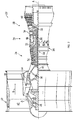
- FIG. 2 a schematic view of a gas turbine engine 20 is shown.
- the gas turbine engine 20 is disclosed herein as a two-spool turbofan that generally incorporates a fan section 22, a compressor section 24, a combustor section 26 and a turbine section 28.
- Alternative engines might include other systems or features.
- the fan section 22 drives air along a bypass flow path B in a bypass duct, while the compressor section 24 drives air along a core flow path C for compression and communication into the combustor section 26 then expansion through the turbine section 28.
- the exemplary engine 20 generally includes a low speed spool 30 and a high speed spool 32 mounted for rotation about an engine central longitudinal axis A relative to an engine static structure 36 via several bearing systems 38. It should be understood that various bearing systems 38 at various locations may alternatively or additionally be provided, and the location of bearing systems 38 may be varied as appropriate to the application.
- the low speed spool 30 generally includes an inner shaft 40 that interconnects a fan 42, a low pressure compressor 44 and a low pressure turbine 46.
- the high speed spool 32 includes an outer shaft 50 that interconnects a high pressure compressor 52 and high pressure turbine 54.
- a combustor 56 is arranged in exemplary gas turbine 20 between the high pressure compressor 52 and the high pressure turbine 54.
- An engine static structure 36 is arranged generally between the high pressure turbine 54 and the low pressure turbine 46.
- the engine static structure 36 further supports bearing systems 38 in the turbine section 28.
- the inner shaft 40 and the outer shaft 50 are concentric and rotate via bearing systems 38 about the engine central longitudinal axis A which is collinear with their longitudinal axes.
- the core airflow is compressed by the low pressure compressor 44 then the high pressure compressor 52, mixed and burned with fuel in the combustor 56, then expanded over the high pressure turbine 54 and low pressure turbine 46.
- the turbines 46, 54 rotationally drive the respective low speed spool 30 and high speed spool 32 in response to the expansion.
- FIG. 3 illustrated is a schematic of an exemplary thermal management system 60 for, thermal management of one or more of the thermal loads of the aircraft 10 (shown in FIG. 1 ).
- the thermal management system 60 is utilized to provide conditioned airflow to cool the one or more thermal loads, such as the aircraft cockpit 12, the cargo hold 14, the passenger cabin 16 or the one or more electronic components 18 or systems of the aircraft 10.
- the thermal management system 60 utilizes airflow from the gas turbine engine 20 of the aircraft as the airflow source for use by the thermal management system 60.
- the source airflow is bleed airflow 62 from the compressor section 24 of the gas turbine engine 20 via a bleed passage 64.
- the bleed passage 64 directs the bleed airflow 62 through a precooler 102 and through an intermediate heat exchanger 66.
- the bleed airflow 62 is expanded at a first turbine 68 downstream of the intermediate heat exchanger 66.
- the expanded and thus cooled bleed airflow 62 is then directed through a first heat exchanger 70.
- the bleed airflow 62 exchanges thermal energy with a first cooling medium 72.
- the first cooling medium 72 may be, for example, air or a liquid refrigerant, and is flowed between the first heat exchanger 70 and a first thermal load 74.
- the bleed airflow 62 cools the first cooling medium 72 at the first heat exchanger 70, and the first cooling medium 72 is directed to the first thermal load 74 to condition or cool the first thermal load 74.
- the bleed airflow 62 is directed back to the intermediate heat exchanger 66 along passageway 76 for thermal exchange with the bleed airflow 62 entering the intermediate heat exchanger 66 via the bleed passage 64.
- the bleed airflow in passageway 76 is directed toward a second turbine 78, where the bleed airflow 62 is expanded and thereby cooled.
- the bleed airflow 62 is then directed through a second heat exchanger 80.
- the bleed airflow 62 exchanges thermal energy with a second cooling medium 82.
- the second cooling medium 82 may be, for example, air or a liquid refrigerant, and is flowed between the second heat exchanger 80 and a second thermal load 84.
- the bleed airflow 62 cools the second cooling medium 82 at the second heat exchanger 80, and the second cooling medium 82 is directed to the second thermal load 84 to condition or cool the second thermal load 84.
- the thermal management system 60 includes a first turbine bypass passage 86 and/or a second turbine bypass passage 88 allowing the bleed airflow 62 to bypass the first turbine 68 or the second turbine 78, respectively.
- a first bypass valve 90 is located at the first turbine bypass passage 86 and is operated to selectably direct the bleed airflow 62 to the first turbine 68 or along the first turbine bypass passage 86 based on, for example, operational needs of the thermal management system 60 for cooling of the first thermal load 74.
- a second bypass valve 92 is located at the second turbine bypass passage 88 and is operated to selectably direct the bleed airflow 62 to the second turbine 78 or along the first turbine bypass passage 88 based on, for example, operational needs of the thermal management system 60 for cooling of the second thermal load 84.
- the thermal energy of the bypass airflow 62 flowing through the first turbine 68 and the second turbine 78 is converted to rotational energy of the first turbine 68 and the second turbine 78.
- This rotational energy is converted to electrical energy by an electrical generator 94 connected to the first turbine 68 and the second turbine 78 through, for example, a first turbine shaft 96 and a second turbine shaft 98, respectively.
- FIG. 3 illustrates the first turbine 68 and the second turbine 78 connected to the same electrical generator 94
- the first turbine 68 and the second turbine 78 may be operably connected to separate electrical generators 94.
- two turbines 68, 78 are shown in the FIGs. and described herein, it is to be appreciated that other quantities of turbines, for example, three, four or five turbines, may be utilized.
- Electrical energy from the electrical generator 94 is utilized by a power distribution system 100 of the aircraft 10 to power components and systems of the aircraft 10.
- the turbines 68, 78 are closely-coupled to the electrical generator 94 and with the heat exchangers 66, 70, 80. Further, the turbines 68, 78 are not connected to a gearbox of the engine 20, and are therefore not dependent on gearbox rotation and loading for operation of the turbines 68, 78., and also eliminates integration concerns with the gearbox. Further, the turbines 68, 78, via the electrical generator 94 provide an additional source of electrical power for the aircraft 10.
Landscapes
- Engineering & Computer Science (AREA)
- Chemical & Material Sciences (AREA)
- Combustion & Propulsion (AREA)
- Aviation & Aerospace Engineering (AREA)
- Mechanical Engineering (AREA)
- General Engineering & Computer Science (AREA)
- Health & Medical Sciences (AREA)
- General Health & Medical Sciences (AREA)
- Pulmonology (AREA)
- Control Of Turbines (AREA)
Abstract
Description
- Exemplary embodiments pertain to the art of environmental control systems (ECSs) for aircraft coupled to a gas turbine engine of the aircraft.
- ECSs provide a supply of conditioned air to an enclosure, such as an aircraft cabin and cockpit, or other heat loads. In a conventional system, a flow of bleed air is taken from a bleed source, for example, an intermediate or high pressure stage of a gas turbine engine compressor. The bleed air is pre-cooled via an air-to-air heat exchanger with heat being rejected to ram air. The pre-cooled bleed air is then flowed to a turbine. After expansion at the turbine the expanded air is flowed across one or more heat exchangers for thermal exchange with cooling flow, either air or liquid. The cooling flow, after being cooled by the airflow at the heat exchanger, is used to cool a heat load, for example, an enclosure, cockpit or component of the aircraft.
- In a typical system, the ECS uses a compressor-turbine set up, known as a bootstrap air cycle. In other ECS systems, turbines are coupled to a gearbox of the gas turbine engine, with the gearbox serving to load the turbines. Such a configuration, however, places the turbines on the engine gearbox, which requires long ducts to the gearbox to provide the airflow thereto. In some operating conditions, the ducts may be at sub-freezing temperatures, resulting in ice accretion in the ducts. The ice restricts flow and inhibits ECS system performance. Further, since the system is connected to the engine gearbox, it will need to be de-clutched from the engine core and loaded in come other manner to achieve cooling performance when the engine is off.
- In one embodiment, a thermal management system for one or more aircraft components includes a bleed airflow source at a gas turbine engine of the aircraft, one or more turbines configured to expand the bleed airflow, thus lowering a temperature of the bleed airflow, the bleed airflow driving rotation of the one or more turbines. One or more heat exchangers are in fluid communication with the one or more turbines. The one or more heat exchangers are configured to exchange thermal energy between the bleed airflow and a thermal load. One or more electrical generators are operably connected to the one or more turbines. The one or more electrical generators are configured to convert rotational energy of the one or more turbines to electrical energy.
- Additionally or alternatively, in this or other embodiments the electrical energy is transmitted to a power management system of the aircraft for use to power one or more aircraft components.
- Additionally or alternatively, in this or other embodiments the one or more turbines are closely coupled to the one or more electrical generators.
- Additionally or alternatively, in this or other embodiments the one or more turbines is at least two turbines, and each turbine of the at least two turbines is operably connected to a different electrical generator of the one or more electrical generators.
- Additionally or alternatively, in this or other embodiments the one or more thermal loads are one or more of an aircraft cockpit, passenger cabin, cargo compartment or one or more components of the aircraft.
- Additionally or alternatively, in this or other embodiments the bleed airflow source is a compressor section of a gas turbine engine.
- Additionally or alternatively, in this or other embodiments the one or more heat exchangers exchange thermal energy between the bleed airflow and a thermal load via a cooling medium flowed between the thermal load and the one or more heat exchangers.
- In another embodiment, an aircraft includes a gas turbine engine, one or more thermal loads, and a thermal management system. The thermal management system includes a bleed airflow source at the gas turbine engine, one or more turbines configured to expand the cooling airflow, thus lowering a temperature of the bleed airflow, the bleed airflow driving rotation of the one or more turbines, and one or more heat exchangers in fluid communication with the one or more turbines. The one or more heat exchangers are configured to exchange thermal energy between the bleed airflow and the one or more thermal loads. One or more electrical generators are operably connected to the one or more turbines. The one or more electrical generators are configured to convert rotational energy of the one or more turbines to electrical energy.
- Additionally or alternatively, in this or other embodiments the electrical energy is transmitted to a power management system of the aircraft for use to power one or more aircraft components.
- Additionally or alternatively, in this or other embodiments the one or more turbines are closely coupled to the one or more electrical generators.
- Additionally or alternatively, in this or other embodiments the one or more turbines is at least two turbines, and each turbine of the at least two turbines is operably connected to a different electrical generator of the one or more electrical generators.
- Additionally or alternatively, in this or other embodiments the one or more thermal loads are one or more of an aircraft cockpit, passenger cabin, cargo compartment or one or more components of the aircraft.
- Additionally or alternatively, in this or other embodiments the bleed airflow source is a compressor section of the gas turbine engine.
- Additionally or alternatively, in this or other embodiments the one or more heat exchangers exchange thermal energy between the bleed airflow and a thermal load via a cooling medium flowed between the thermal load and the one or more heat exchangers.
- In another embodiment, a method of thermal management of one or more aircraft components includes urging a bleed airflow from a bleed airflow source at a gas turbine engine of the aircraft toward one or more turbines of a thermal management system, expanding and cooling the bleed airflow at the one or more turbines, thereby rotating the one or more turbines, urging the cooling airflow through one or more heat exchangers for thermal energy exchange with one or more thermal loads, and converting the rotational energy of the one or more turbines to electrical energy at an electrical generator operably connected to the one or more turbines.
- Additionally or alternatively, in this or other embodiments the electrical energy is transmitted to a power management system of the aircraft for use to power one or more aircraft components.
- Additionally or alternatively, in this or other embodiments the one or more turbines is at least two turbines, and each turbine of the at least two turbines is operably connected to a different electrical generator of the one or more electrical generators.
- Additionally or alternatively, in this or other embodiments the one or more thermal loads are one or more of an aircraft cockpit, passenger cabin, cargo compartment or one or more components of the aircraft.
- Additionally or alternatively, in this or other embodiments urging the bleed airflow from the bleed airflow source includes urging the bleed airflow from a compressor section of gas turbine engine.
- Additionally or alternatively, in this or other embodiments the one or more heat exchangers exchange thermal energy between the bleed airflow and a thermal load via a cooling medium flowed between the thermal load and the one or more heat exchangers.
- The following descriptions should not be considered limiting in any way. With reference to the accompanying drawings, like elements are numbered alike:
-
FIG. 1 is a schematic illustration of an aircraft; -
FIG. 2 is a partial cross-sectional view of an embodiment of a gas turbine engine of an aircraft; and -
FIG. 3 is a schematic illustration of an embodiment of a thermal management system for one or more components of an aircraft. - A detailed description of one or more embodiments of the disclosed apparatus and method are presented herein by way of exemplification and not limitation with reference to the Figures.
- Referring to
FIG. 1 , shown is a schematic illustration of anaircraft 10. Theaircraft 10 includes one or more areas or components that are thermal loads and require cooling or other thermal management. Such thermal loads may include anaircraft cockpit 12, cargo hold 14,passenger cabin 16 or one or moreelectronic components 18 or systems throughout theaircraft 10. Theaircraft 10 is powered by one or moregas turbine engines 20. - Referring to
FIG. 2 , a schematic view of agas turbine engine 20 is shown. Thegas turbine engine 20 is disclosed herein as a two-spool turbofan that generally incorporates afan section 22, acompressor section 24, acombustor section 26 and aturbine section 28. Alternative engines might include other systems or features. Thefan section 22 drives air along a bypass flow path B in a bypass duct, while thecompressor section 24 drives air along a core flow path C for compression and communication into thecombustor section 26 then expansion through theturbine section 28. Although depicted as a two-spool turbofan gas turbine engine in the disclosed non-limiting embodiment, it should be understood that the concepts described herein are not limited to use with two-spool turbofans as the teachings may be applied to other types of turbine engines including single-spool and three-spool architectures. - The
exemplary engine 20 generally includes alow speed spool 30 and ahigh speed spool 32 mounted for rotation about an engine central longitudinal axis A relative to an enginestatic structure 36 viaseveral bearing systems 38. It should be understood thatvarious bearing systems 38 at various locations may alternatively or additionally be provided, and the location ofbearing systems 38 may be varied as appropriate to the application. - The
low speed spool 30 generally includes aninner shaft 40 that interconnects a fan 42, alow pressure compressor 44 and alow pressure turbine 46. Thehigh speed spool 32 includes anouter shaft 50 that interconnects ahigh pressure compressor 52 andhigh pressure turbine 54. Acombustor 56 is arranged inexemplary gas turbine 20 between thehigh pressure compressor 52 and thehigh pressure turbine 54. An enginestatic structure 36 is arranged generally between thehigh pressure turbine 54 and thelow pressure turbine 46. The enginestatic structure 36 furthersupports bearing systems 38 in theturbine section 28. Theinner shaft 40 and theouter shaft 50 are concentric and rotate via bearingsystems 38 about the engine central longitudinal axis A which is collinear with their longitudinal axes. - The core airflow is compressed by the
low pressure compressor 44 then thehigh pressure compressor 52, mixed and burned with fuel in thecombustor 56, then expanded over thehigh pressure turbine 54 andlow pressure turbine 46. Theturbines low speed spool 30 andhigh speed spool 32 in response to the expansion. - Referring to
FIG. 3 , illustrated is a schematic of an exemplarythermal management system 60 for, thermal management of one or more of the thermal loads of the aircraft 10 (shown inFIG. 1 ). Thethermal management system 60 is utilized to provide conditioned airflow to cool the one or more thermal loads, such as theaircraft cockpit 12, thecargo hold 14, thepassenger cabin 16 or the one or moreelectronic components 18 or systems of theaircraft 10. Thethermal management system 60 utilizes airflow from thegas turbine engine 20 of the aircraft as the airflow source for use by thethermal management system 60. - In some embodiments, the source airflow is bleed
airflow 62 from thecompressor section 24 of thegas turbine engine 20 via ableed passage 64. Thebleed passage 64 directs thebleed airflow 62 through aprecooler 102 and through an intermediate heat exchanger 66. Thebleed airflow 62 is expanded at afirst turbine 68 downstream of the intermediate heat exchanger 66. The expanded and thus cooledbleed airflow 62 is then directed through afirst heat exchanger 70. At thefirst heat exchanger 70, thebleed airflow 62 exchanges thermal energy with afirst cooling medium 72. Thefirst cooling medium 72 may be, for example, air or a liquid refrigerant, and is flowed between thefirst heat exchanger 70 and a firstthermal load 74. Thebleed airflow 62 cools thefirst cooling medium 72 at thefirst heat exchanger 70, and thefirst cooling medium 72 is directed to the firstthermal load 74 to condition or cool the firstthermal load 74. - From the
first heat exchanger 70, thebleed airflow 62 is directed back to the intermediate heat exchanger 66 alongpassageway 76 for thermal exchange with thebleed airflow 62 entering the intermediate heat exchanger 66 via thebleed passage 64. Upon leaving the intermediate heat exchanger 66, the bleed airflow inpassageway 76 is directed toward asecond turbine 78, where thebleed airflow 62 is expanded and thereby cooled. Thebleed airflow 62 is then directed through asecond heat exchanger 80. At thesecond heat exchanger 80, thebleed airflow 62 exchanges thermal energy with a second cooling medium 82. The second cooling medium 82 may be, for example, air or a liquid refrigerant, and is flowed between thesecond heat exchanger 80 and a secondthermal load 84. Thebleed airflow 62 cools the second cooling medium 82 at thesecond heat exchanger 80, and the second cooling medium 82 is directed to the secondthermal load 84 to condition or cool the secondthermal load 84. - In some embodiments, the
thermal management system 60 includes a firstturbine bypass passage 86 and/or a secondturbine bypass passage 88 allowing thebleed airflow 62 to bypass thefirst turbine 68 or thesecond turbine 78, respectively. Afirst bypass valve 90 is located at the firstturbine bypass passage 86 and is operated to selectably direct thebleed airflow 62 to thefirst turbine 68 or along the firstturbine bypass passage 86 based on, for example, operational needs of thethermal management system 60 for cooling of the firstthermal load 74. Similarly, asecond bypass valve 92 is located at the secondturbine bypass passage 88 and is operated to selectably direct thebleed airflow 62 to thesecond turbine 78 or along the firstturbine bypass passage 88 based on, for example, operational needs of thethermal management system 60 for cooling of the secondthermal load 84. - The thermal energy of the
bypass airflow 62 flowing through thefirst turbine 68 and thesecond turbine 78 is converted to rotational energy of thefirst turbine 68 and thesecond turbine 78. This rotational energy is converted to electrical energy by anelectrical generator 94 connected to thefirst turbine 68 and thesecond turbine 78 through, for example, afirst turbine shaft 96 and asecond turbine shaft 98, respectively. WhileFIG. 3 illustrates thefirst turbine 68 and thesecond turbine 78 connected to the sameelectrical generator 94, in other embodiments thefirst turbine 68 and thesecond turbine 78 may be operably connected to separateelectrical generators 94. Further, while twoturbines - Electrical energy from the
electrical generator 94 is utilized by apower distribution system 100 of theaircraft 10 to power components and systems of theaircraft 10. In some embodiments, theturbines electrical generator 94 and with theheat exchangers turbines engine 20, and are therefore not dependent on gearbox rotation and loading for operation of theturbines 68, 78., and also eliminates integration concerns with the gearbox. Further, theturbines electrical generator 94 provide an additional source of electrical power for theaircraft 10. - The term "about" is intended to include the degree of error associated with measurement of the particular quantity based upon the equipment available at the time of filing the application.
- The terminology used herein is for the purpose of describing particular embodiments only and is not intended to be limiting of the present disclosure. As used herein, the singular forms "a", "an" and "the" are intended to include the plural forms as well, unless the context clearly indicates otherwise. It will be further understood that the terms "comprises" and/or "comprising," when used in this specification, specify the presence of stated features, integers, steps, operations, elements, and/or components, but do not preclude the presence or addition of one or more other features, integers, steps, operations, element components, and/or groups thereof.
- While the present disclosure has been described with reference to an exemplary embodiment or embodiments, it will be understood by those skilled in the art that various changes may be made and equivalents may be substituted for elements thereof without departing from the scope of the present disclosure. In addition, many modifications may be made to adapt a particular situation or material to the teachings of the present disclosure without departing from the essential scope thereof. Therefore, it is intended that the present disclosure not be limited to the particular embodiment disclosed as the best mode contemplated for carrying out this present disclosure, but that the present disclosure will include all embodiments falling within the scope of the claims.
Claims (14)
- A thermal management system for one or more aircraft components, comprising:a bleed airflow source at a gas turbine engine (20) of the aircraft;one or more turbines (68) configured to expand the bleed airflow, thus lowering a temperature of the bleed airflow, the bleed airflow driving rotation of the one or more turbines;one or more heat exchangers (70) in fluid communication with the one or more turbines, the one or more heat exchangers configured to exchange thermal energy between the bleed airflow and a thermal load; andone or more electrical generators (94) operably connected to the one or more turbines, the one or more electrical generators configured to convert rotational energy of the one or more turbines to electrical energy.
- The thermal management system of claim 1, wherein the electrical energy is transmitted to a power management system of the aircraft for use to power one or more aircraft components.
- The thermal management system of claim 1 or 2, wherein the one or more turbines are closely coupled to the one or more electrical generators.
- The thermal management system of any preceding claim, wherein the one or more turbines is at least two turbines, and each turbine of the at least two turbines is operably connected to a different electrical generator of the one or more electrical generators.
- The thermal management system of any preceding claim, wherein the one or more thermal loads are one or more of an aircraft cockpit, passenger cabin, cargo compartment or one or more components of the aircraft.
- The thermal management system of any preceding claim, wherein the bleed airflow source is a compressor section of a gas turbine engine.
- The thermal management system of any preceding claim, wherein the one or more heat exchangers exchange thermal energy between the bleed airflow and a thermal load via a cooling medium flowed between the thermal load and the one or more heat exchangers.
- An aircraft comprising:a gas turbine engine;one or more thermal loads; andthe thermal management system of any preceding claim, including:
the one or more heat exchangers configured to exchange thermal energy between the bleed airflow and the one or more thermal loads. - A method of thermal management of one or more aircraft components, comprising:urging a bleed airflow from a bleed airflow source at a gas turbine engine (20) of the aircraft toward one or more turbines of a thermal management system;expanding and cooling the bleed airflow at the one or more turbines (68), thereby rotating the one or more turbines;urging the cooling airflow through one or more heat exchangers (70) for thermal energy exchange with one or more thermal loads; andconverting the rotational energy of the one or more turbines to electrical energy at an electrical generator (94) operably connected to the one or more turbines.
- The method of claim 9, further comprising transmitting the electrical energy to a power management system of the aircraft for use to power one or more aircraft components.
- The method of claim 9 or 10, wherein the one or more turbines is at least two turbines, and each turbine of the at least two turbines is operably connected to a different electrical generator of the one or more electrical generators.
- The method of any of claims 9 to 11, wherein the one or more thermal loads are one or more of an aircraft cockpit, passenger cabin, cargo compartment or one or more components of the aircraft.
- The method of any of claims 9 to 12, wherein urging the bleed airflow from the bleed airflow source comprises urging the bleed airflow from a compressor section of gas turbine engine.
- The method of any of claims 9 to 13, wherein the one or more heat exchangers exchange thermal energy between the bleed airflow and a thermal load via a cooling medium flowed between the thermal load and the one or more heat exchangers.
Applications Claiming Priority (1)
| Application Number | Priority Date | Filing Date | Title |
|---|---|---|---|
| US16/397,165 US11286857B2 (en) | 2019-04-29 | 2019-04-29 | Turbine-turbine generator power thermal management system |
Publications (2)
| Publication Number | Publication Date |
|---|---|
| EP3733520A1 true EP3733520A1 (en) | 2020-11-04 |
| EP3733520B1 EP3733520B1 (en) | 2023-05-03 |
Family
ID=68731840
Family Applications (1)
| Application Number | Title | Priority Date | Filing Date |
|---|---|---|---|
| EP19212129.1A Active EP3733520B1 (en) | 2019-04-29 | 2019-11-28 | Thermal management system with cooling turbine and generator |
Country Status (2)
| Country | Link |
|---|---|
| US (1) | US11286857B2 (en) |
| EP (1) | EP3733520B1 (en) |
Families Citing this family (9)
| Publication number | Priority date | Publication date | Assignee | Title |
|---|---|---|---|---|
| US11221186B2 (en) * | 2019-07-18 | 2022-01-11 | Hamilton Sundstrand Corporation | Heat exchanger closure bar with shield |
| EP4334211A1 (en) * | 2021-05-07 | 2024-03-13 | ZeroAvia, Inc. | Cooling architecture for hydrogen fuel cell-powered aircraft |
| US11788465B2 (en) * | 2022-01-19 | 2023-10-17 | General Electric Company | Bleed flow assembly for a gas turbine engine |
| US12291337B2 (en) | 2022-02-18 | 2025-05-06 | Rtx Corporation | Aircraft hybrid cooling system |
| US11913377B2 (en) | 2022-02-18 | 2024-02-27 | Rtx Corporation | Environmental control systems |
| US12583615B2 (en) | 2023-06-30 | 2026-03-24 | Hamilton Sundstrand Corporation | Environmental control system with liquid hydrogen fuel vaporization for a combustion engine |
| US12583614B2 (en) | 2023-06-30 | 2026-03-24 | Hamilton Sundstrand Corporation | Environmental control system with liquid hydrogen fuel vaporization for a hydrogen fuel cell |
| US12473093B2 (en) * | 2023-06-30 | 2025-11-18 | Hamilton Sundstrand Corporation | Outflow energy recovery system |
| US12378888B1 (en) | 2024-02-01 | 2025-08-05 | Rtx Corporation | Airfoil-mounted acoustic resonator array for gas turbine engine component |
Citations (6)
| Publication number | Priority date | Publication date | Assignee | Title |
|---|---|---|---|---|
| US5899085A (en) * | 1997-08-01 | 1999-05-04 | Mcdonnell Douglas Corporation | Integrated air conditioning and power unit |
| EP1279594A1 (en) * | 2001-07-27 | 2003-01-29 | Honeywell Normalair-Garrett (Holdings) Limited | Air cycle cooling system |
| US20130111917A1 (en) * | 2011-11-03 | 2013-05-09 | Northrop Grumman Systems Corporation | Apparatus for aircraft with high peak power equipment |
| EP2647571A1 (en) * | 2012-04-04 | 2013-10-09 | Airbus Operations GmbH | Method for controlling an aircraft air conditioning system during maintenance |
| EP3263866A1 (en) * | 2016-06-29 | 2018-01-03 | Airbus Operations GmbH | System and method for generating electrical energy in a vehicle |
| EP3489488A1 (en) * | 2017-11-28 | 2019-05-29 | United Technologies Corporation | Complex air supply system for gas turbine engine and associated aircraft |
Family Cites Families (22)
| Publication number | Priority date | Publication date | Assignee | Title |
|---|---|---|---|---|
| US4503666A (en) * | 1983-05-16 | 1985-03-12 | Rockwell International Corporation | Aircraft environmental control system with auxiliary power output |
| US5442905A (en) | 1994-04-08 | 1995-08-22 | Alliedsignal Inc. | Integrated power and cooling environmental control system |
| US5461882A (en) | 1994-07-22 | 1995-10-31 | United Technologies Corporation | Regenerative condensing cycle |
| US5924293A (en) * | 1997-07-11 | 1999-07-20 | Alliedsignal Inc. | Air cycle environmental control system with fully energy regenerative high pressure water condensation and extraction |
| US6124646A (en) | 1998-02-11 | 2000-09-26 | Alliedsignal Inc. | Aircraft air conditioning system including electric generator for providing AC power having limited frequency range |
| US5939800A (en) | 1998-02-11 | 1999-08-17 | Alliedsignal Inc. | Aircraft electrical power system including air conditioning system generator |
| US6148622A (en) * | 1998-04-03 | 2000-11-21 | Alliedsignal Inc. | Environmental control system no condenser high pressure water separation system |
| US6128909A (en) * | 1998-06-04 | 2000-10-10 | Alliedsignal Inc. | Air cycle environmental control systems with two stage compression and expansion and separate ambient air fan |
| US6415595B1 (en) * | 2000-08-22 | 2002-07-09 | Hamilton Sundstrand Corporation | Integrated thermal management and coolant system for an aircraft |
| US6526775B1 (en) * | 2001-09-14 | 2003-03-04 | The Boeing Company | Electric air conditioning system for an aircraft |
| US6615606B2 (en) * | 2002-01-10 | 2003-09-09 | Hamilton Sundstrand | Dual turbine bootstrap cycle environmental control system |
| US6848261B2 (en) * | 2003-04-03 | 2005-02-01 | Honeywell International Inc. | Condensing cycle with energy recovery augmentation |
| GB0414341D0 (en) * | 2004-06-26 | 2004-07-28 | Honeywell Normalair Garrett | Closed loop air conditioning system |
| US8347647B2 (en) * | 2004-09-22 | 2013-01-08 | Hamilton Sundstrand Corporation | Air cycle machine for an aircraft environmental control system |
| US7779644B2 (en) * | 2006-07-31 | 2010-08-24 | Hamilton Sundstrand Corporation | Air cycle machine for an aircraft environmental control system |
| US8019522B2 (en) | 2008-09-30 | 2011-09-13 | General Electric Company | Method and system for providing cooling and power |
| US9669936B1 (en) | 2012-10-24 | 2017-06-06 | The Boeing Company | Aircraft air conditioning systems and methods |
| US20150314878A1 (en) * | 2014-05-02 | 2015-11-05 | Hamilton Sundstrand Corporation | Aircraft environmental conditioning system and method |
| US10155592B2 (en) * | 2014-05-05 | 2018-12-18 | Hamilton Sundstrand Corporation | Environmental control system with air cycle machine bypass shutoff valves |
| US10160547B2 (en) * | 2015-05-26 | 2018-12-25 | Hamilton Sundstrand Corporation | Aircraft environmental control system |
| US9534538B1 (en) | 2015-10-27 | 2017-01-03 | General Electric Company | Systems and methods for integrated power and thermal management in a turbine-powered aircraft |
| US11077949B2 (en) * | 2018-10-05 | 2021-08-03 | The Boeing Company | Dual turbine thermal management system (TMS) |
-
2019
- 2019-04-29 US US16/397,165 patent/US11286857B2/en active Active
- 2019-11-28 EP EP19212129.1A patent/EP3733520B1/en active Active
Patent Citations (6)
| Publication number | Priority date | Publication date | Assignee | Title |
|---|---|---|---|---|
| US5899085A (en) * | 1997-08-01 | 1999-05-04 | Mcdonnell Douglas Corporation | Integrated air conditioning and power unit |
| EP1279594A1 (en) * | 2001-07-27 | 2003-01-29 | Honeywell Normalair-Garrett (Holdings) Limited | Air cycle cooling system |
| US20130111917A1 (en) * | 2011-11-03 | 2013-05-09 | Northrop Grumman Systems Corporation | Apparatus for aircraft with high peak power equipment |
| EP2647571A1 (en) * | 2012-04-04 | 2013-10-09 | Airbus Operations GmbH | Method for controlling an aircraft air conditioning system during maintenance |
| EP3263866A1 (en) * | 2016-06-29 | 2018-01-03 | Airbus Operations GmbH | System and method for generating electrical energy in a vehicle |
| EP3489488A1 (en) * | 2017-11-28 | 2019-05-29 | United Technologies Corporation | Complex air supply system for gas turbine engine and associated aircraft |
Also Published As
| Publication number | Publication date |
|---|---|
| US20200340403A1 (en) | 2020-10-29 |
| US11286857B2 (en) | 2022-03-29 |
| EP3733520B1 (en) | 2023-05-03 |
Similar Documents
| Publication | Publication Date | Title |
|---|---|---|
| EP3733520B1 (en) | Thermal management system with cooling turbine and generator | |
| US9863318B2 (en) | Thermal management system for gas turbine engine | |
| US11286853B2 (en) | Cooling system | |
| US9957051B2 (en) | Method of operating a multi-pack environmental control system | |
| US10160547B2 (en) | Aircraft environmental control system | |
| EP1295789B1 (en) | Environmental control system | |
| US6415595B1 (en) | Integrated thermal management and coolant system for an aircraft | |
| US20120192578A1 (en) | Gas turbine bleed ecs cooling | |
| US10830133B2 (en) | Aircraft environmental control system selectively powered by three bleed ports | |
| JPH04224235A (en) | Auxiliary cooling air system | |
| US20220145796A1 (en) | Combustion engine including turbomachine | |
| US11465770B2 (en) | Air cycle machine connected to engine gearbox | |
| US12378914B2 (en) | Fuel management system | |
| US20250263170A1 (en) | Aircraft Hybrid Cooling System | |
| US11454424B2 (en) | Air cycle machines and methods of communicating fluid through air cycle machines | |
| EP3623290B1 (en) | Two-turbine environmental control system | |
| EP4336029A1 (en) | A thermal management system for an aircraft | |
| EP3112268B1 (en) | Aircraft environmental control system selectively powered by three bleed ports | |
| Erez et al. | DESIGN OF A RAM AIR DRIVEN REVERSE BOOTSTRAP AIRCYCLE FOR AIRCRAFT PODS |
Legal Events
| Date | Code | Title | Description |
|---|---|---|---|
| PUAI | Public reference made under article 153(3) epc to a published international application that has entered the european phase |
Free format text: ORIGINAL CODE: 0009012 |
|
| STAA | Information on the status of an ep patent application or granted ep patent |
Free format text: STATUS: THE APPLICATION HAS BEEN PUBLISHED |
|
| AK | Designated contracting states |
Kind code of ref document: A1 Designated state(s): AL AT BE BG CH CY CZ DE DK EE ES FI FR GB GR HR HU IE IS IT LI LT LU LV MC MK MT NL NO PL PT RO RS SE SI SK SM TR |
|
| AX | Request for extension of the european patent |
Extension state: BA ME |
|
| STAA | Information on the status of an ep patent application or granted ep patent |
Free format text: STATUS: REQUEST FOR EXAMINATION WAS MADE |
|
| 17P | Request for examination filed |
Effective date: 20210504 |
|
| RBV | Designated contracting states (corrected) |
Designated state(s): AL AT BE BG CH CY CZ DE DK EE ES FI FR GB GR HR HU IE IS IT LI LT LU LV MC MK MT NL NO PL PT RO RS SE SI SK SM TR |
|
| STAA | Information on the status of an ep patent application or granted ep patent |
Free format text: STATUS: EXAMINATION IS IN PROGRESS |
|
| 17Q | First examination report despatched |
Effective date: 20210923 |
|
| GRAP | Despatch of communication of intention to grant a patent |
Free format text: ORIGINAL CODE: EPIDOSNIGR1 |
|
| STAA | Information on the status of an ep patent application or granted ep patent |
Free format text: STATUS: GRANT OF PATENT IS INTENDED |
|
| INTG | Intention to grant announced |
Effective date: 20221212 |
|
| GRAS | Grant fee paid |
Free format text: ORIGINAL CODE: EPIDOSNIGR3 |
|
| GRAA | (expected) grant |
Free format text: ORIGINAL CODE: 0009210 |
|
| STAA | Information on the status of an ep patent application or granted ep patent |
Free format text: STATUS: THE PATENT HAS BEEN GRANTED |
|
| AK | Designated contracting states |
Kind code of ref document: B1 Designated state(s): AL AT BE BG CH CY CZ DE DK EE ES FI FR GB GR HR HU IE IS IT LI LT LU LV MC MK MT NL NO PL PT RO RS SE SI SK SM TR |
|
| REG | Reference to a national code |
Ref country code: GB Ref legal event code: FG4D |
|
| REG | Reference to a national code |
Ref country code: DE Ref legal event code: R096 Ref document number: 602019028316 Country of ref document: DE |
|
| REG | Reference to a national code |
Ref country code: AT Ref legal event code: REF Ref document number: 1564404 Country of ref document: AT Kind code of ref document: T Effective date: 20230515 Ref country code: CH Ref legal event code: EP |
|
| REG | Reference to a national code |
Ref country code: IE Ref legal event code: FG4D |
|
| REG | Reference to a national code |
Ref country code: LT Ref legal event code: MG9D |
|
| REG | Reference to a national code |
Ref country code: NL Ref legal event code: MP Effective date: 20230503 |
|
| REG | Reference to a national code |
Ref country code: AT Ref legal event code: MK05 Ref document number: 1564404 Country of ref document: AT Kind code of ref document: T Effective date: 20230503 |
|
| PG25 | Lapsed in a contracting state [announced via postgrant information from national office to epo] |
Ref country code: SE Free format text: LAPSE BECAUSE OF FAILURE TO SUBMIT A TRANSLATION OF THE DESCRIPTION OR TO PAY THE FEE WITHIN THE PRESCRIBED TIME-LIMIT Effective date: 20230503 Ref country code: PT Free format text: LAPSE BECAUSE OF FAILURE TO SUBMIT A TRANSLATION OF THE DESCRIPTION OR TO PAY THE FEE WITHIN THE PRESCRIBED TIME-LIMIT Effective date: 20230904 Ref country code: NO Free format text: LAPSE BECAUSE OF FAILURE TO SUBMIT A TRANSLATION OF THE DESCRIPTION OR TO PAY THE FEE WITHIN THE PRESCRIBED TIME-LIMIT Effective date: 20230803 Ref country code: NL Free format text: LAPSE BECAUSE OF FAILURE TO SUBMIT A TRANSLATION OF THE DESCRIPTION OR TO PAY THE FEE WITHIN THE PRESCRIBED TIME-LIMIT Effective date: 20230503 Ref country code: ES Free format text: LAPSE BECAUSE OF FAILURE TO SUBMIT A TRANSLATION OF THE DESCRIPTION OR TO PAY THE FEE WITHIN THE PRESCRIBED TIME-LIMIT Effective date: 20230503 Ref country code: AT Free format text: LAPSE BECAUSE OF FAILURE TO SUBMIT A TRANSLATION OF THE DESCRIPTION OR TO PAY THE FEE WITHIN THE PRESCRIBED TIME-LIMIT Effective date: 20230503 |
|
| PG25 | Lapsed in a contracting state [announced via postgrant information from national office to epo] |
Ref country code: RS Free format text: LAPSE BECAUSE OF FAILURE TO SUBMIT A TRANSLATION OF THE DESCRIPTION OR TO PAY THE FEE WITHIN THE PRESCRIBED TIME-LIMIT Effective date: 20230503 Ref country code: PL Free format text: LAPSE BECAUSE OF FAILURE TO SUBMIT A TRANSLATION OF THE DESCRIPTION OR TO PAY THE FEE WITHIN THE PRESCRIBED TIME-LIMIT Effective date: 20230503 Ref country code: LV Free format text: LAPSE BECAUSE OF FAILURE TO SUBMIT A TRANSLATION OF THE DESCRIPTION OR TO PAY THE FEE WITHIN THE PRESCRIBED TIME-LIMIT Effective date: 20230503 Ref country code: LT Free format text: LAPSE BECAUSE OF FAILURE TO SUBMIT A TRANSLATION OF THE DESCRIPTION OR TO PAY THE FEE WITHIN THE PRESCRIBED TIME-LIMIT Effective date: 20230503 Ref country code: IS Free format text: LAPSE BECAUSE OF FAILURE TO SUBMIT A TRANSLATION OF THE DESCRIPTION OR TO PAY THE FEE WITHIN THE PRESCRIBED TIME-LIMIT Effective date: 20230903 Ref country code: HR Free format text: LAPSE BECAUSE OF FAILURE TO SUBMIT A TRANSLATION OF THE DESCRIPTION OR TO PAY THE FEE WITHIN THE PRESCRIBED TIME-LIMIT Effective date: 20230503 Ref country code: GR Free format text: LAPSE BECAUSE OF FAILURE TO SUBMIT A TRANSLATION OF THE DESCRIPTION OR TO PAY THE FEE WITHIN THE PRESCRIBED TIME-LIMIT Effective date: 20230804 |
|
| PG25 | Lapsed in a contracting state [announced via postgrant information from national office to epo] |
Ref country code: FI Free format text: LAPSE BECAUSE OF FAILURE TO SUBMIT A TRANSLATION OF THE DESCRIPTION OR TO PAY THE FEE WITHIN THE PRESCRIBED TIME-LIMIT Effective date: 20230503 |
|
| PG25 | Lapsed in a contracting state [announced via postgrant information from national office to epo] |
Ref country code: SK Free format text: LAPSE BECAUSE OF FAILURE TO SUBMIT A TRANSLATION OF THE DESCRIPTION OR TO PAY THE FEE WITHIN THE PRESCRIBED TIME-LIMIT Effective date: 20230503 |
|
| PG25 | Lapsed in a contracting state [announced via postgrant information from national office to epo] |
Ref country code: SM Free format text: LAPSE BECAUSE OF FAILURE TO SUBMIT A TRANSLATION OF THE DESCRIPTION OR TO PAY THE FEE WITHIN THE PRESCRIBED TIME-LIMIT Effective date: 20230503 Ref country code: SK Free format text: LAPSE BECAUSE OF FAILURE TO SUBMIT A TRANSLATION OF THE DESCRIPTION OR TO PAY THE FEE WITHIN THE PRESCRIBED TIME-LIMIT Effective date: 20230503 Ref country code: RO Free format text: LAPSE BECAUSE OF FAILURE TO SUBMIT A TRANSLATION OF THE DESCRIPTION OR TO PAY THE FEE WITHIN THE PRESCRIBED TIME-LIMIT Effective date: 20230503 Ref country code: EE Free format text: LAPSE BECAUSE OF FAILURE TO SUBMIT A TRANSLATION OF THE DESCRIPTION OR TO PAY THE FEE WITHIN THE PRESCRIBED TIME-LIMIT Effective date: 20230503 Ref country code: DK Free format text: LAPSE BECAUSE OF FAILURE TO SUBMIT A TRANSLATION OF THE DESCRIPTION OR TO PAY THE FEE WITHIN THE PRESCRIBED TIME-LIMIT Effective date: 20230503 Ref country code: CZ Free format text: LAPSE BECAUSE OF FAILURE TO SUBMIT A TRANSLATION OF THE DESCRIPTION OR TO PAY THE FEE WITHIN THE PRESCRIBED TIME-LIMIT Effective date: 20230503 |
|
| REG | Reference to a national code |
Ref country code: DE Ref legal event code: R097 Ref document number: 602019028316 Country of ref document: DE |
|
| PLBE | No opposition filed within time limit |
Free format text: ORIGINAL CODE: 0009261 |
|
| STAA | Information on the status of an ep patent application or granted ep patent |
Free format text: STATUS: NO OPPOSITION FILED WITHIN TIME LIMIT |
|
| 26N | No opposition filed |
Effective date: 20240206 |
|
| PG25 | Lapsed in a contracting state [announced via postgrant information from national office to epo] |
Ref country code: SI Free format text: LAPSE BECAUSE OF FAILURE TO SUBMIT A TRANSLATION OF THE DESCRIPTION OR TO PAY THE FEE WITHIN THE PRESCRIBED TIME-LIMIT Effective date: 20230503 |
|
| PG25 | Lapsed in a contracting state [announced via postgrant information from national office to epo] |
Ref country code: SI Free format text: LAPSE BECAUSE OF FAILURE TO SUBMIT A TRANSLATION OF THE DESCRIPTION OR TO PAY THE FEE WITHIN THE PRESCRIBED TIME-LIMIT Effective date: 20230503 |
|
| REG | Reference to a national code |
Ref country code: CH Ref legal event code: PL |
|
| PG25 | Lapsed in a contracting state [announced via postgrant information from national office to epo] |
Ref country code: MC Free format text: LAPSE BECAUSE OF FAILURE TO SUBMIT A TRANSLATION OF THE DESCRIPTION OR TO PAY THE FEE WITHIN THE PRESCRIBED TIME-LIMIT Effective date: 20230503 |
|
| PG25 | Lapsed in a contracting state [announced via postgrant information from national office to epo] |
Ref country code: LU Free format text: LAPSE BECAUSE OF NON-PAYMENT OF DUE FEES Effective date: 20231128 |
|
| PG25 | Lapsed in a contracting state [announced via postgrant information from national office to epo] |
Ref country code: CH Free format text: LAPSE BECAUSE OF NON-PAYMENT OF DUE FEES Effective date: 20231130 |
|
| PG25 | Lapsed in a contracting state [announced via postgrant information from national office to epo] |
Ref country code: MC Free format text: LAPSE BECAUSE OF FAILURE TO SUBMIT A TRANSLATION OF THE DESCRIPTION OR TO PAY THE FEE WITHIN THE PRESCRIBED TIME-LIMIT Effective date: 20230503 Ref country code: LU Free format text: LAPSE BECAUSE OF NON-PAYMENT OF DUE FEES Effective date: 20231128 Ref country code: CH Free format text: LAPSE BECAUSE OF NON-PAYMENT OF DUE FEES Effective date: 20231130 |
|
| REG | Reference to a national code |
Ref country code: BE Ref legal event code: MM Effective date: 20231130 |
|
| REG | Reference to a national code |
Ref country code: IE Ref legal event code: MM4A |
|
| PG25 | Lapsed in a contracting state [announced via postgrant information from national office to epo] |
Ref country code: IE Free format text: LAPSE BECAUSE OF NON-PAYMENT OF DUE FEES Effective date: 20231128 |
|
| PG25 | Lapsed in a contracting state [announced via postgrant information from national office to epo] |
Ref country code: BE Free format text: LAPSE BECAUSE OF NON-PAYMENT OF DUE FEES Effective date: 20231130 |
|
| PG25 | Lapsed in a contracting state [announced via postgrant information from national office to epo] |
Ref country code: IE Free format text: LAPSE BECAUSE OF NON-PAYMENT OF DUE FEES Effective date: 20231128 Ref country code: BE Free format text: LAPSE BECAUSE OF NON-PAYMENT OF DUE FEES Effective date: 20231130 |
|
| PG25 | Lapsed in a contracting state [announced via postgrant information from national office to epo] |
Ref country code: BG Free format text: LAPSE BECAUSE OF FAILURE TO SUBMIT A TRANSLATION OF THE DESCRIPTION OR TO PAY THE FEE WITHIN THE PRESCRIBED TIME-LIMIT Effective date: 20230503 |
|
| PG25 | Lapsed in a contracting state [announced via postgrant information from national office to epo] |
Ref country code: BG Free format text: LAPSE BECAUSE OF FAILURE TO SUBMIT A TRANSLATION OF THE DESCRIPTION OR TO PAY THE FEE WITHIN THE PRESCRIBED TIME-LIMIT Effective date: 20230503 |
|
| PG25 | Lapsed in a contracting state [announced via postgrant information from national office to epo] |
Ref country code: CY Free format text: LAPSE BECAUSE OF FAILURE TO SUBMIT A TRANSLATION OF THE DESCRIPTION OR TO PAY THE FEE WITHIN THE PRESCRIBED TIME-LIMIT; INVALID AB INITIO Effective date: 20191128 |
|
| PG25 | Lapsed in a contracting state [announced via postgrant information from national office to epo] |
Ref country code: HU Free format text: LAPSE BECAUSE OF FAILURE TO SUBMIT A TRANSLATION OF THE DESCRIPTION OR TO PAY THE FEE WITHIN THE PRESCRIBED TIME-LIMIT; INVALID AB INITIO Effective date: 20191128 |
|
| PG25 | Lapsed in a contracting state [announced via postgrant information from national office to epo] |
Ref country code: TR Free format text: LAPSE BECAUSE OF FAILURE TO SUBMIT A TRANSLATION OF THE DESCRIPTION OR TO PAY THE FEE WITHIN THE PRESCRIBED TIME-LIMIT Effective date: 20230503 |
|
| PGFP | Annual fee paid to national office [announced via postgrant information from national office to epo] |
Ref country code: DE Payment date: 20251022 Year of fee payment: 7 |
|
| PGFP | Annual fee paid to national office [announced via postgrant information from national office to epo] |
Ref country code: GB Payment date: 20251023 Year of fee payment: 7 |
|
| PGFP | Annual fee paid to national office [announced via postgrant information from national office to epo] |
Ref country code: IT Payment date: 20251022 Year of fee payment: 7 |
|
| PGFP | Annual fee paid to national office [announced via postgrant information from national office to epo] |
Ref country code: FR Payment date: 20251022 Year of fee payment: 7 |
|
| P01 | Opt-out of the competence of the unified patent court (upc) registered |
Free format text: CASE NUMBER: UPC_APP_0018878_3733520/2025 Effective date: 20251222 |