EP3733503A1 - One piece multifunctional nanolaminated composite window pane - Google Patents
One piece multifunctional nanolaminated composite window pane Download PDFInfo
- Publication number
- EP3733503A1 EP3733503A1 EP20172622.1A EP20172622A EP3733503A1 EP 3733503 A1 EP3733503 A1 EP 3733503A1 EP 20172622 A EP20172622 A EP 20172622A EP 3733503 A1 EP3733503 A1 EP 3733503A1
- Authority
- EP
- European Patent Office
- Prior art keywords
- structural
- window assembly
- layer
- panel
- protection
- Prior art date
- Legal status (The legal status is an assumption and is not a legal conclusion. Google has not performed a legal analysis and makes no representation as to the accuracy of the status listed.)
- Granted
Links
Images

Classifications
-
- B—PERFORMING OPERATIONS; TRANSPORTING
- B64—AIRCRAFT; AVIATION; COSMONAUTICS
- B64C—AEROPLANES; HELICOPTERS
- B64C1/00—Fuselages; Constructional features common to fuselages, wings, stabilising surfaces or the like
- B64C1/14—Windows; Doors; Hatch covers or access panels; Surrounding frame structures; Canopies; Windscreens accessories therefor, e.g. pressure sensors, water deflectors, hinges, seals, handles, latches, windscreen wipers
- B64C1/1476—Canopies; Windscreens or similar transparent elements
- B64C1/1492—Structure and mounting of the transparent elements in the window or windscreen
-
- B—PERFORMING OPERATIONS; TRANSPORTING
- B32—LAYERED PRODUCTS
- B32B—LAYERED PRODUCTS, i.e. PRODUCTS BUILT-UP OF STRATA OF FLAT OR NON-FLAT, e.g. CELLULAR OR HONEYCOMB, FORM
- B32B3/00—Layered products comprising a layer with external or internal discontinuities or unevennesses, or a layer of non-planar shape; Layered products comprising a layer having particular features of form
- B32B3/26—Layered products comprising a layer with external or internal discontinuities or unevennesses, or a layer of non-planar shape; Layered products comprising a layer having particular features of form characterised by a particular shape of the outline of the cross-section of a continuous layer; characterised by a layer with cavities or internal voids ; characterised by an apertured layer
- B32B3/263—Layered products comprising a layer with external or internal discontinuities or unevennesses, or a layer of non-planar shape; Layered products comprising a layer having particular features of form characterised by a particular shape of the outline of the cross-section of a continuous layer; characterised by a layer with cavities or internal voids ; characterised by an apertured layer characterised by a layer having non-uniform thickness
-
- B—PERFORMING OPERATIONS; TRANSPORTING
- B64—AIRCRAFT; AVIATION; COSMONAUTICS
- B64F—GROUND OR AIRCRAFT-CARRIER-DECK INSTALLATIONS SPECIALLY ADAPTED FOR USE IN CONNECTION WITH AIRCRAFT; DESIGNING, MANUFACTURING, ASSEMBLING, CLEANING, MAINTAINING OR REPAIRING AIRCRAFT, NOT OTHERWISE PROVIDED FOR; HANDLING, TRANSPORTING, TESTING OR INSPECTING AIRCRAFT COMPONENTS, NOT OTHERWISE PROVIDED FOR
- B64F5/00—Designing, manufacturing, assembling, cleaning, maintaining or repairing aircraft, not otherwise provided for; Handling, transporting, testing or inspecting aircraft components, not otherwise provided for
- B64F5/10—Manufacturing or assembling aircraft, e.g. jigs therefor
-
- C—CHEMISTRY; METALLURGY
- C08—ORGANIC MACROMOLECULAR COMPOUNDS; THEIR PREPARATION OR CHEMICAL WORKING-UP; COMPOSITIONS BASED THEREON
- C08J—WORKING-UP; GENERAL PROCESSES OF COMPOUNDING; AFTER-TREATMENT NOT COVERED BY SUBCLASSES C08B, C08C, C08F, C08G or C08H
- C08J7/00—Chemical treatment or coating of shaped articles made of macromolecular substances
- C08J7/04—Coating
- C08J7/042—Coating with two or more layers, where at least one layer of a composition contains a polymer binder
- C08J7/0423—Coating with two or more layers, where at least one layer of a composition contains a polymer binder with at least one layer of inorganic material and at least one layer of a composition containing a polymer binder
-
- C—CHEMISTRY; METALLURGY
- C08—ORGANIC MACROMOLECULAR COMPOUNDS; THEIR PREPARATION OR CHEMICAL WORKING-UP; COMPOSITIONS BASED THEREON
- C08K—Use of inorganic or non-macromolecular organic substances as compounding ingredients
- C08K3/00—Use of inorganic substances as compounding ingredients
- C08K3/02—Elements
- C08K3/04—Carbon
- C08K3/041—Carbon nanotubes
-
- C—CHEMISTRY; METALLURGY
- C08—ORGANIC MACROMOLECULAR COMPOUNDS; THEIR PREPARATION OR CHEMICAL WORKING-UP; COMPOSITIONS BASED THEREON
- C08K—Use of inorganic or non-macromolecular organic substances as compounding ingredients
- C08K3/00—Use of inorganic substances as compounding ingredients
- C08K3/02—Elements
- C08K3/04—Carbon
- C08K3/042—Graphene or derivatives, e.g. graphene oxides
-
- C—CHEMISTRY; METALLURGY
- C08—ORGANIC MACROMOLECULAR COMPOUNDS; THEIR PREPARATION OR CHEMICAL WORKING-UP; COMPOSITIONS BASED THEREON
- C08K—Use of inorganic or non-macromolecular organic substances as compounding ingredients
- C08K3/00—Use of inorganic substances as compounding ingredients
- C08K3/18—Oxygen-containing compounds, e.g. metal carbonyls
- C08K3/20—Oxides; Hydroxides
- C08K3/22—Oxides; Hydroxides of metals
-
- C—CHEMISTRY; METALLURGY
- C08—ORGANIC MACROMOLECULAR COMPOUNDS; THEIR PREPARATION OR CHEMICAL WORKING-UP; COMPOSITIONS BASED THEREON
- C08K—Use of inorganic or non-macromolecular organic substances as compounding ingredients
- C08K3/00—Use of inorganic substances as compounding ingredients
- C08K3/34—Silicon-containing compounds
- C08K3/36—Silica
-
- C—CHEMISTRY; METALLURGY
- C08—ORGANIC MACROMOLECULAR COMPOUNDS; THEIR PREPARATION OR CHEMICAL WORKING-UP; COMPOSITIONS BASED THEREON
- C08L—COMPOSITIONS OF MACROMOLECULAR COMPOUNDS
- C08L25/00—Compositions of, homopolymers or copolymers of compounds having one or more unsaturated aliphatic radicals, each having only one carbon-to-carbon double bond, and at least one being terminated by an aromatic carbocyclic ring; Compositions of derivatives of such polymers
- C08L25/02—Homopolymers or copolymers of hydrocarbons
- C08L25/04—Homopolymers or copolymers of styrene
- C08L25/06—Polystyrene
-
- B—PERFORMING OPERATIONS; TRANSPORTING
- B32—LAYERED PRODUCTS
- B32B—LAYERED PRODUCTS, i.e. PRODUCTS BUILT-UP OF STRATA OF FLAT OR NON-FLAT, e.g. CELLULAR OR HONEYCOMB, FORM
- B32B2255/00—Coating on the layer surface
- B32B2255/20—Inorganic coating
-
- B—PERFORMING OPERATIONS; TRANSPORTING
- B32—LAYERED PRODUCTS
- B32B—LAYERED PRODUCTS, i.e. PRODUCTS BUILT-UP OF STRATA OF FLAT OR NON-FLAT, e.g. CELLULAR OR HONEYCOMB, FORM
- B32B2255/00—Coating on the layer surface
- B32B2255/26—Polymeric coating
-
- B—PERFORMING OPERATIONS; TRANSPORTING
- B32—LAYERED PRODUCTS
- B32B—LAYERED PRODUCTS, i.e. PRODUCTS BUILT-UP OF STRATA OF FLAT OR NON-FLAT, e.g. CELLULAR OR HONEYCOMB, FORM
- B32B2307/00—Properties of the layers or laminate
- B32B2307/20—Properties of the layers or laminate having particular electrical or magnetic properties, e.g. piezoelectric
- B32B2307/212—Electromagnetic interference shielding
-
- B—PERFORMING OPERATIONS; TRANSPORTING
- B32—LAYERED PRODUCTS
- B32B—LAYERED PRODUCTS, i.e. PRODUCTS BUILT-UP OF STRATA OF FLAT OR NON-FLAT, e.g. CELLULAR OR HONEYCOMB, FORM
- B32B2605/00—Vehicles
- B32B2605/18—Aircraft
-
- C—CHEMISTRY; METALLURGY
- C08—ORGANIC MACROMOLECULAR COMPOUNDS; THEIR PREPARATION OR CHEMICAL WORKING-UP; COMPOSITIONS BASED THEREON
- C08J—WORKING-UP; GENERAL PROCESSES OF COMPOUNDING; AFTER-TREATMENT NOT COVERED BY SUBCLASSES C08B, C08C, C08F, C08G or C08H
- C08J2425/00—Characterised by the use of homopolymers or copolymers of compounds having one or more unsaturated aliphatic radicals, each having only one carbon-to-carbon double bond, and at least one being terminated by an aromatic carbocyclic ring; Derivatives of such polymers
- C08J2425/02—Homopolymers or copolymers of hydrocarbons
- C08J2425/04—Homopolymers or copolymers of styrene
- C08J2425/06—Polystyrene
-
- C—CHEMISTRY; METALLURGY
- C08—ORGANIC MACROMOLECULAR COMPOUNDS; THEIR PREPARATION OR CHEMICAL WORKING-UP; COMPOSITIONS BASED THEREON
- C08J—WORKING-UP; GENERAL PROCESSES OF COMPOUNDING; AFTER-TREATMENT NOT COVERED BY SUBCLASSES C08B, C08C, C08F, C08G or C08H
- C08J2479/00—Characterised by the use of macromolecular compounds obtained by reactions forming in the main chain of the macromolecule a linkage containing nitrogen with or without oxygen, or carbon only, not provided for in groups C08J2461/00 - C08J2477/00
- C08J2479/04—Polycondensates having nitrogen-containing heterocyclic rings in the main chain; Polyhydrazides; Polyamide acids or similar polyimide precursors
- C08J2479/08—Polyimides; Polyester-imides; Polyamide-imides; Polyamide acids or similar polyimide precursors
-
- C—CHEMISTRY; METALLURGY
- C08—ORGANIC MACROMOLECULAR COMPOUNDS; THEIR PREPARATION OR CHEMICAL WORKING-UP; COMPOSITIONS BASED THEREON
- C08K—Use of inorganic or non-macromolecular organic substances as compounding ingredients
- C08K3/00—Use of inorganic substances as compounding ingredients
- C08K3/18—Oxygen-containing compounds, e.g. metal carbonyls
- C08K3/20—Oxides; Hydroxides
- C08K3/22—Oxides; Hydroxides of metals
- C08K2003/2227—Oxides; Hydroxides of metals of aluminium
-
- C—CHEMISTRY; METALLURGY
- C08—ORGANIC MACROMOLECULAR COMPOUNDS; THEIR PREPARATION OR CHEMICAL WORKING-UP; COMPOSITIONS BASED THEREON
- C08K—Use of inorganic or non-macromolecular organic substances as compounding ingredients
- C08K3/00—Use of inorganic substances as compounding ingredients
- C08K3/18—Oxygen-containing compounds, e.g. metal carbonyls
- C08K3/20—Oxides; Hydroxides
- C08K3/22—Oxides; Hydroxides of metals
- C08K2003/2237—Oxides; Hydroxides of metals of titanium
Definitions
- the present disclosure generally relates to window assemblies and, more particularly, to methods and systems for frameless, structural window assemblies.
- Window assemblies for vehicles or structures typically include windows made of glass, plastic, or composite materials mounted in a frame.
- the frame supports the window and reinforces the cutout in the vehicle or structure in which the window is installed.
- an aircraft window assembly generally includes a window formed of two panes of acrylic mounted in a metal frame. The window fits into a cutout in the aircraft skin and the metal frame mechanically attaches to the aircraft skin forming the fuselage. The frame insures that the structural load is born by the frame instead of the acrylic windows.
- FIG. 1 depicts an aircraft 100 including an enlarged cross-sectional view of a window assembly 110.
- Window assembly 110 consists of an inner window 120 and an outer window 125 both formed of acrylic. Inner window 120 and outer window 125 and are attached to and supported by a frame 130.
- Frame 130 is attached to an aircraft skin 190 of aircraft 100 by a plurality of fasteners 185.
- Window assemblies that include a frame, however, have several limitations.
- the cutouts can increase the local stress, for example, in the aircraft skin.
- a material property mismatch between the acrylic windows and the metal frame can generate local stress at the cutout.
- the frame provides structural support to the window assembly, it also adds weight and limits window size.
- acrylic windows are not ideal because acrylic has low thermal conductivity and low strength. As a result, window sizes are generally small affecting passenger experience. And, because acrylic windows are not electrically conductive, additional electromagnetic effect (EME) solutions need to be added to the window and frame.
- EME electromagnetic effect
- a window assembly includes a protection panel comprising a protection panel edge and a structural panel disposed on the protection panel.
- the structural panel comprises a structural panel edge that extends beyond the protection panel edge.
- the structural panel may have a tensile stress of about 30 ksi to about 2,000 ksi and the window assembly may have a transmissivity of about 45% to about 99% to visible light.
- the window assembly includes a protection panel comprising a surface barrier layer, and an electromagnetic effect (EME) protection coating disposed on the surface barrier layer.
- the window assembly further includes a structural panel disposed on the protection panel.
- the structural panel comprises a bottom surface protection layer, a structural layer disposed on the bottom surface protection layer, and a transparent conductive coating layer disposed on the structural layer.
- the window assembly may have a transmissivity of about 45% to about 99% to visible light.
- a method for making a frameless, nanolaminated window assembly includes forming a bottom surface protection layer by depositing a first reinforcement layer comprising one or more layers of Al 2 O 3 , one or more layers of graphene, or one or more layers of Al 2 O 3 and graphene and then depositing a first transparent polymer layer comprising a thermoplastic material on the first reinforcement layer.
- the method further includes forming a structural layer disposed on the bottom surface protection layer by depositing a second reinforcement layer comprising one or more layers of Al 2 O 3 , one or more layers of graphene, one or more layers SiO 2 , or a combination thereof, then depositing a second transparent polymer layer comprising a thermoplastic material on the second reinforcement layer, and depositing a third reinforcement layer comprising one or more layers of Al 2 O 3 , one or more layers of graphene, or one or more layers of Al 2 O 3 and graphene on the second transparent polymer layer.
- the method further includes forming a transparent conductive coating layer comprising one or more of ITO and graphene on the third reinforcement layer.
- the method further includes forming a surface barrier layer on the transparent conductive coating layer by depositing a third transparent polymer layer comprising a thermoplastic material on the transparent conductive coating layer and depositing a fourth reinforcement layer comprising one or more layers of Al 2 O 3 , one or more layers of graphene, or one or more layers of Al 2 O 3 and graphene on the third transparent polymer layer.
- the method further includes depositing an electromagnetic effect coating on the fourth reinforcement layer.
- window assemblies include a transparent window mounted in a frame. While the frame provides structural support for the window assembly, it also adds weight and limits the size of the window. Glass, plastics or composite window materials are generally low strength and may also require additional coatings to prevent ice build-up and protect against EME. Implementations of the present disclosure address the need for a one piece structural window that can be directly attached, for example to a vehicle, equipment, or structure, without a frame (or frameless).
- the disclosed nanolaminated window assembly is self-supporting, therefore eliminating the need for a frame for support.
- the self-supporting nature of the nanolaminated window allows direct attachment to the aircraft skin to provide structural support and load bearing capability. Because no frame is needed, the disclosed nanolaminated window can also provide a larger window area with reduced weight.
- the one piece multifunctional design can provide one or more of impact protection, ice buildup prevention, and EME protection.
- nano-laminate and “nanolaminated” refer to a composite material formed by alternating layers of materials having a thickness in a range of about 20 nm to about 1,000 nm.
- Use of nanolaminated layers in the disclosed window assemblies provides the ability to tailor specific properties of the window assembly including one or more of thickness, composition, isotropic stiffness, and strength.
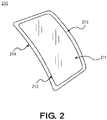
- FIG. 2 depicts a window assembly 210 in accordance with the present teachings.
- window assembly 210 is described with reference to an aircraft window, one of ordinary skill in the art will understand that the disclosed window assembly can be used for other purposes including, but not limited to, vehicles, equipment, and buildings and other structures.
- the one piece design of window assembly 210 includes a protection panel 211 and a structural panel 213.
- Structural panel 213 provides structural support and impact protection for window assembly 210. It further allows mounting without use of a frame. Protection panel 211 provides resistance to one or more of electromagnetic effect (EME), icing, scratching, and corrosion.
- EME electromagnetic effect
- Structural panel 213 is disposed on and attached to protection panel 211.
- Both protection panel 211 and structural panel 213 are formed of a plurality of nanolaminated layers. Structural panel 213 is larger than protection panel 211 so a structural panel edge 214 extends beyond a protection panel edge 212. As further discussed below, a portion of structural panel 213 that extends beyond protection panel edge 212 can be used to attach window assembly 210, for example, to an aircraft skin forming a fuselage without need for a frame. Protection panel 211 is sized to fill a cutout and sit flush, for example, with an outside of the aircraft fuselage. It provides a view through the aircraft fuselage, prevents air drag and provides surface protection from EME, ice, and corrosion. Structural panel 213 provides load bearing capability to window assembly 210 and a location to attach window assembly 210 to, for example, the aircraft skin forming the fuselage.
- window assembly 210 is transparent, for example having a transmissivity of about 45% to about 99% to visible light. It can optionally have a transmissivity of about 55% to about 98%, or about 65% to about 95% to visible light. Transmissivity can be measured, for example, using ASTM-D1003 with a hazemeter (Byk Gardner).
- a shape of window assembly 210 is generally a polygon or a polygon with rounded corners, where the rounded corners have a radius arc r c of about 0.25 inches or more.
- the shape of window assembly 210 can also range from a convex shape with a radius R of about 5 inches or more to an essentially flat shape with an infinite radius. This can allow window assembly 210 to mount flush with, for example, an aircraft fuselage having a curvature or equipment/structure having no curvature.
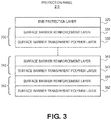
- protection panel 211 can include a surface barrier layer 330 and an electromagnetic effect (EME) protection layer 320.
- EME protection layer 320 has a thickness of about 50 nm to about 20,000 nm and is formed of carbon nanotubes or indium tin oxide (ITO) with graphene.
- EME protection layer 320 is disposed on surface barrier layer 330.
- Surface barrier layer 330 is formed of a plurality of nanolaminated layers including a surface barrier reinforcement layer 331.
- Surface barrier reinforcement layer 331 is formed of Al 2 O 3 or graphene and has a thickness of about 500 nm to about 50,000 nm.
- Surface barrier reinforcement layer 331 serves as a moisture barrier for corrosion protection and provides protection from impact, scratching, and burn thorough.
- Surface barrier reinforcement layer 331 is disposed on a surface barrier transparent polymer layer 332.
- Surface barrier transparent polymer layer 332 has a thickness of about 20 nm to about 2,000 nm and is formed of a high temperature thermoplastic material having a glass transition temperature Tg of about 120°F to about 750°F, including, but not limited to, polystyrene (PS), polyetherimide (PEI), and mixtures thereof.
- PS polystyrene
- PEI polyetherimide
- Protection panel 211 can optionally include one or more additional surface barrier layers having similar thickness and composition to surface barrier layer 330, as shown in FIG. 3 .
- the additional one or more surface barrier layers can serve as fail safe layers against corrosion, scratching, impact, and burn through.
- protection panel 211 can include two or more surface barrier layers, for example, surface barrier layer 340 and surface barrier layer 350.
- Surface barrier layer 340 can include a surface barrier reinforcement layer 341 formed of Al 2 O 3 or graphene and having a thickness of about 500 nm to about 50,000 nm.
- Surface barrier reinforcement layer 341 can be disposed on surface barrier transparent polymer layer 342, have a thickness of about 20 nm to about 2,000 nm, and be formed of a high temperature thermoplastic material including, but not limited to, polystyrene (PS), polyetherimide (PEI), and mixtures thereof.
- surface barrier layer 350 can include a surface barrier reinforcement layer 351 formed of Al 2 O 3 or graphene, have a thickness of about 500 nm to about 50,000 nm.
- Surface barrier reinforcement layer 351 can be disposed on surface barrier transparent polymer layer 352, have a thickness of about 20 nm to about 2,000 nm, and be formed of a high temperature thermoplastic material including, but not limited to, polystyrene (PS) and polyetherimide (PEI). Protection panel 211 can further optionally include additional surface barrier reinforcement layers or surface barrier transparent polymer layers.
- PS polystyrene
- PEI polyetherimide
- Protection panel 211 has a thickness of about 0.05 to about 0.8 inches and provides resistance to one or more of EME, icing, and corrosion. When window assembly 210 is used in an aircraft, protection panel 211 can be sized to provide an increased view outside of the aircraft and mounted flush to the outside of the fuselage to prevent air drag.
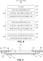
- structural panel 213 can include a transparent conductive coating (TCC) layer 420, a structural layer 430, and a bottom surface protection layer 450.
- TCC transparent conductive coating
- Structural panel 213 is formed of a plurality of nanolaminated layers and has a thickness of about 0.04 inches to about 0.6 inches.
- TCC layer 420 has a thickness of about 50 nm to about 10,000 nm and can be formed of carbon nanotubes or ITO with graphene to provide EME protection. TCC layer 420 is disposed on structural layer 430.
- Structural layer 430 is formed of a plurality of nanolaminated layers and includes one or more first structural reinforcement layers 431, where each first structural reinforcement layer has a thickness of about 20 nm to about 1,000 nm.
- the one or more first structural reinforcement layers 431 are disposed on a structural transparent polymer layer 432 having a thickness of about 20 nm to about 1,000 nm.
- Structural transparent polymer layer 432 is disposed on one or more second structural reinforcement layer 433, where each second structural reinforcement layer has a thickness of about 20 nm to about 1,000 nm.
- First structural reinforcement layer 431 and second structural reinforcement layer 433 can be formed of Al 2 O 3 , SiO 2 , or graphene.
- Structural transparent polymer layer 432 can be formed of a high temperature thermoplastic material including, but not limited to, polystyrene (PS) and polyetherimide (PEI).
- the high temperature thermoplastic material can have a glass transition temperature of at least 120°F or more.
- Structural panel 213 can optionally include one or more additional structural layers.
- Structural panel 213, for example, can include two or more structural layers, such as structural layer 440 as shown in FIG 4 .
- Structural layer 440 can include: i) one or more first structural reinforcement layers 441 each having a thickness of about 20 nm to about 1,000 nm and formed of Al 2 O 3 or graphene or SiO 2 ; ii) a structural transparent polymer layer 442, having a thickness of about 20 nm to about 1,000 nm and formed of a high temperature thermoplastic material including, but not limited to, polystyrene (PS) and polyetherimide (PEI); and, iii) one or more second structural reinforcement layers 443 each having a thickness of about 20 nm to about 1,000 nm and formed of Al 2 O 3 , SiO 2 , or graphene.
- PS polystyrene
- PEI polyetherimide
- Structural panel 213 further includes a bottom surface protection layer 450 formed of a plurality of nanolaminated layers.
- Bottom surface protection layer 450 includes a bottom surface transparent polymer layer 451 formed of a high temperature thermoplastic material including, but not limited to, polystyrene (PS) and polyetherimide (PEI), and having a thickness of about 20 nm to about 1,000 nm.
- Bottom surface transparent polymer layer 451 is disposed on bottom surface reinforcement layer 452.
- Bottom surface reinforcement layer 452 is formed of Al 2 O 3 or graphene and can have a thickness of about 20 nm to about 1,000 nm.
- structural panel 213 When window assembly 210 is attached to a vehicle, equipment, or structure, structural panel 213 bears the load. Accordingly, structural panel 213 can include about 33% to about 90% volume fraction of Al 2 O 3 and/or graphene or SiO 2 with at least about 5% to about 30% volume fraction of Al 2 O 3 . Structural panel 213 can have a tensile strength (which may also be referred to as tensile stress limit, i.e.
- Tensile strength, tensile stress and modulus of structural panel 213 can be measured, for example, using ASTM-D3039-17. Bearing strength can be measured, for example, using ASTM-D5961-17.
- bearing strength may be ultimate bearing strength measured as specified in Fig.1 of ASTM-D5961-17 utilizing procedure A, at room temperature, under ambient conditions and using a steel protruding head fastener.
- structural panel 213 can have a coefficient of thermal expansion of about 5 to about 20 ppm in/in/°F. Coefficient of thermal expansion can be measured, for example, using ASTM-E831-14. Glass transition temperature (Tg) can be measured, for example, using ASTM-D7028-07 (R2015).
- Structural panel 213 can have a von Mises stress of about 10 ksi to about 200 ksi. The von Mises stress can be determined, for example, using Abaqus FEA software available from Dassault Systemes (Johnstown, RI).
- FIG. 5 depicts a cross sectional view of a window assembly 510 mounted in an aircraft in accordance with the teachings of the present disclosure.
- Window assembly 510 includes a protection panel 511 and a structural panel 513.
- Window assembly 510 is mounted to an aircraft skin 590, for example forming a fuselage, without use of a frame, for example, using one or more fasteners 585 and/or adhesive to attach structural panel 513 to aircraft skin 590.
- Structural panel can include a tapered edge 514 having an angle of about 12 to about 90 degrees. Tapered edge 514 minimizes local stress at and near edges of structural panel 513.
- Protection panel 511 can be sized to fit into a cutout in aircraft skin 590.
- protection panel 511 can include a tapered edge 512 having an angle of about 30 to about 80 degrees. Tapered edge 512 allows window assembly 510 to attach and seal securely to aircraft skin 590. Because aircraft skin 590 has a curved surface, window assembly 510 can have a convex shape and a radius of curvature R to match aircraft skin 590. Both protection panel 511 and structural panel 513 have a polygon shape with multiple edges connected by a radius arc r c of at least 0.25 inches. To enable mounting to aircraft skin 590 without a frame, a distance 519 from edge 512 to edge 514 can be 0.375 inches or more.
- Window assembly 510 can optionally include an electronic shade 599, for example, a smart sensor based electronic shade, to reduce the amount of light that reaches the interior of the aircraft through window assembly 510.
- Electronic shade 599 can be made of electrochromic glass layers deposited onto an inside 515 of window assembly 510 or self-sticking electrochromic films attached to inside 515 of window assembly 510.
- Electronic shade 599 can be controlled by smart light sensors 516 to reduce or increase an amount of sunlight entering through window assembly 510, for example, by turning from clear to dark blue or gray to reduce the amount of sunlight.
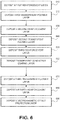
- a method 600 for forming window assembly 510 by depositing a plurality of nanolaminated layers is shown in FIG. 6 .
- Each of the plurality of nanolaminated layers can be deposited using vacuum vapor depositional processes including, but not limited to, physical vapor deposition (PVD), chemical vapor deposition (CVD), pulsed laser deposition (PLD), and/or vacuum spraying.
- PVD physical vapor deposition
- CVD chemical vapor deposition
- PLD pulsed laser deposition
- a structural panel for example, structural panel 213 shown in FIGS. 2 and 3 or structural panel 513 shown in FIG. 5 , can be formed by deposing a plurality of nanolaminated layers to form a bottom surface protection layer, one or more structural layers, and a transparent conductive coating (TCC) layer.
- TCC transparent conductive coating
- a bottom surface protection layer is formed by depositing a first reinforcement layer comprising one or more layers of Al 2 O 3 , one or more layers of graphene, or one or more layers of Al 2 O 3 and graphene.
- a first transparent polymer layer comprising a thermoplastic material is then deposited on the first reinforcement layer.
- one or more structural layers can be formed on the bottom surface protection layer by depositing a second reinforcement layer comprising one or more layers of Al 2 O 3 , one or more layers of graphene, one or more layers SiO 2 , or a combination thereof, on the bottom surface protection layer.
- a second transparent polymer layer comprising a thermoplastic material can be deposited on the second reinforcement layer at 640 of method 600.
- a third reinforcement layer comprising one or more layers of Al 2 O 3 , one or more layers of graphene, or one or more layers of Al 2 O 3 and graphene can be deposited on the second transparent polymer layer at 650 of method 600. Additional structural layers can be formed by repeating 630 to 650 of method 600 shown in FIG. 6 .
- a transparent conductive coating layer comprising one or more of ITO and graphene on the third reinforcement layer is formed on the third reinforcement layer.
- protection panel for example protection panel 211 as shown in FIGS. 2 and 3 or protection panel 511 shown in FIG. 5 can then formed on the structural panel.
- a surface barrier layer is formed by depositing a third transparent polymer layer comprising a thermoplastic material on the transparent conductive coating layer.
- a fourth reinforcement layer comprising one or more layers of Al 2 O 3 , one or more layers of graphene, or one or more layers of Al 2 O 3 and graphene is deposited on the third transparent polymer layer. Additional surface barrier layers can be formed by repeating 670 to 680 of method 600.
- the protection panel is completed by depositing an electromagnetic effect coating on the fourth reinforcement layer as shown at 690 of method 600.
- fabrication of one piece multifunction window assembly 510 using method 600 can be accomplished by forming the structural panel after forming the protection panel.
- 670 to 690 of method 600 can be performed prior 630 to 660 of method 600 being performed.
- fabrication of the structural panel and/ or protection panel can be in a piecemeal manner.
- a first group of several layers can be deposited and a second group of several layers can be separately deposited.
- the first group of layers can then be bonded to the second group of layers.
- a first structural layer composed of a first group of layers can be formed by performing 630 to 650 of method 600 shown in FIG. 6 .
- a second structural layer composed of a second group of layers can then be separately formed by performing 630 to 650 of method 600.
- the first structural layer and the second structural layer can then be bonded together to form a portion of a structural panel, for example, structural panel 513 shown in FIG. 5 .
- Bonding can use, for example, glue that has a similar transparency and a similar or higher glass transition temperature Tg compared to the transparent thermoplastic material forming the structural panel and/or the protection panel.
- method 600 to form one piece multifunction window assembly 510 allows the number of layers, the placement of the layers relative to each other, the composition of the layers, and the thickness of the layers to be controlled. This can result in improved properties, including isotropic stiffness and strength and reduced defects that can be tailored for specific use and environments. Additionally, method 600 can be used to form net-shape or near net shape window assemblies of desired dimensions, so no pre-trimming or post-trimming is needed.
Landscapes
- Chemical & Material Sciences (AREA)
- Engineering & Computer Science (AREA)
- Medicinal Chemistry (AREA)
- Polymers & Plastics (AREA)
- Organic Chemistry (AREA)
- Chemical Kinetics & Catalysis (AREA)
- Health & Medical Sciences (AREA)
- Aviation & Aerospace Engineering (AREA)
- Mechanical Engineering (AREA)
- Manufacturing & Machinery (AREA)
- Transportation (AREA)
- Inorganic Chemistry (AREA)
- Materials Engineering (AREA)
- Nanotechnology (AREA)
- Laminated Bodies (AREA)
- Aiming, Guidance, Guns With A Light Source, Armor, Camouflage, And Targets (AREA)
- Joining Of Glass To Other Materials (AREA)
Abstract
Description
- The present disclosure generally relates to window assemblies and, more particularly, to methods and systems for frameless, structural window assemblies.
- Window assemblies for vehicles or structures typically include windows made of glass, plastic, or composite materials mounted in a frame. The frame supports the window and reinforces the cutout in the vehicle or structure in which the window is installed. For example, an aircraft window assembly generally includes a window formed of two panes of acrylic mounted in a metal frame. The window fits into a cutout in the aircraft skin and the metal frame mechanically attaches to the aircraft skin forming the fuselage. The frame insures that the structural load is born by the frame instead of the acrylic windows.
FIG. 1 depicts anaircraft 100 including an enlarged cross-sectional view of awindow assembly 110.Window assembly 110 consists of aninner window 120 and anouter window 125 both formed of acrylic.Inner window 120 andouter window 125 and are attached to and supported by aframe 130.Frame 130 is attached to anaircraft skin 190 ofaircraft 100 by a plurality offasteners 185. - Window assemblies that include a frame, however, have several limitations. The cutouts can increase the local stress, for example, in the aircraft skin. And, a material property mismatch between the acrylic windows and the metal frame can generate local stress at the cutout. While the frame provides structural support to the window assembly, it also adds weight and limits window size.
- Particularly for aircraft applications, acrylic windows are not ideal because acrylic has low thermal conductivity and low strength. As a result, window sizes are generally small affecting passenger experience. And, because acrylic windows are not electrically conductive, additional electromagnetic effect (EME) solutions need to be added to the window and frame.
- According to the present teachings, a window assembly is provided. The window assembly includes a protection panel comprising a protection panel edge and a structural panel disposed on the protection panel. The structural panel comprises a structural panel edge that extends beyond the protection panel edge. The structural panel may have a tensile stress of about 30 ksi to about 2,000 ksi and the window assembly may have a transmissivity of about 45% to about 99% to visible light.
- According to the present teachings, another window assembly is provided. The window assembly includes a protection panel comprising a surface barrier layer, and an electromagnetic effect (EME) protection coating disposed on the surface barrier layer. The window assembly further includes a structural panel disposed on the protection panel. The structural panel comprises a bottom surface protection layer, a structural layer disposed on the bottom surface protection layer, and a transparent conductive coating layer disposed on the structural layer. The window assembly may have a transmissivity of about 45% to about 99% to visible light.
- According to the present teachings, a method for making a frameless, nanolaminated window assembly is provided. The method includes forming a bottom surface protection layer by depositing a first reinforcement layer comprising one or more layers of Al2O3, one or more layers of graphene, or one or more layers of Al2O3 and graphene and then depositing a first transparent polymer layer comprising a thermoplastic material on the first reinforcement layer. The method further includes forming a structural layer disposed on the bottom surface protection layer by depositing a second reinforcement layer comprising one or more layers of Al2O3, one or more layers of graphene, one or more layers SiO2, or a combination thereof, then depositing a second transparent polymer layer comprising a thermoplastic material on the second reinforcement layer, and depositing a third reinforcement layer comprising one or more layers of Al2O3, one or more layers of graphene, or one or more layers of Al2O3 and graphene on the second transparent polymer layer. The method further includes forming a transparent conductive coating layer comprising one or more of ITO and graphene on the third reinforcement layer. The method further includes forming a surface barrier layer on the transparent conductive coating layer by depositing a third transparent polymer layer comprising a thermoplastic material on the transparent conductive coating layer and depositing a fourth reinforcement layer comprising one or more layers of Al2O3, one or more layers of graphene, or one or more layers of Al2O3 and graphene on the third transparent polymer layer. The method further includes depositing an electromagnetic effect coating on the fourth reinforcement layer.
- It is to be understood that both the foregoing general description and the following detailed description are exemplary and explanatory only and are not restrictive of the disclosure, as claimed.
- The accompanying drawings, which are incorporated in and constitute a part of this specification, illustrate the present disclosure and together with the description, serve to explain the principles of the present disclosure.
-
FIG. 1 schematically depicts a conventional window assembly mounted in an aircraft and an enlarged cross-sectional view of the conventional window assembly. -
FIG. 2 schematically depicts a nanolaminated window in accordance with the present teachings. -
FIG. 3 schematically depicts a plurality of nanolaminated layers forming a protection panel in accordance with the present teachings. -
FIG. 4 schematically depicts a plurality of nanolaminated layers forming a structural panel in accordance with the present teachings. -
FIG. 5 schematically depicts a cross-sectional view of a nanolaminated window in accordance with the present teachings. -
FIG. 6 is a flowchart depicting a method for making a nanolaminated window assembly in accordance with the present teachings - Reference will now be made in detail to exemplary implementations of the present disclosure, examples of which are illustrated in the accompanying drawings. Wherever possible, the same reference numbers will be used throughout the drawings to refer to the same or like parts. In the following description, reference is made to the accompanying drawings that form a part thereof, and in which is shown by way of illustration specific exemplary implementations in which the present disclosure may be practiced. These implementations are described in sufficient detail to enable those skilled in the art to practice the present disclosure and it is to be understood that other implementations may be utilized and that changes may be made without departing from the scope of the present disclosure. The following description is, therefore, merely exemplary.
- Currently, window assemblies include a transparent window mounted in a frame. While the frame provides structural support for the window assembly, it also adds weight and limits the size of the window. Glass, plastics or composite window materials are generally low strength and may also require additional coatings to prevent ice build-up and protect against EME. Implementations of the present disclosure address the need for a one piece structural window that can be directly attached, for example to a vehicle, equipment, or structure, without a frame (or frameless).
- The disclosed nanolaminated window assembly is self-supporting, therefore eliminating the need for a frame for support. For particular applications, such as in an aircraft, the self-supporting nature of the nanolaminated window allows direct attachment to the aircraft skin to provide structural support and load bearing capability. Because no frame is needed, the disclosed nanolaminated window can also provide a larger window area with reduced weight. And, the one piece multifunctional design can provide one or more of impact protection, ice buildup prevention, and EME protection.
- As used herein, the term "nano-laminate" and "nanolaminated" refer to a composite material formed by alternating layers of materials having a thickness in a range of about 20 nm to about 1,000 nm. Use of nanolaminated layers in the disclosed window assemblies provides the ability to tailor specific properties of the window assembly including one or more of thickness, composition, isotropic stiffness, and strength.
-
FIG. 2 depicts awindow assembly 210 in accordance with the present teachings. Althoughwindow assembly 210 is described with reference to an aircraft window, one of ordinary skill in the art will understand that the disclosed window assembly can be used for other purposes including, but not limited to, vehicles, equipment, and buildings and other structures. The one piece design ofwindow assembly 210 includes aprotection panel 211 and astructural panel 213.Structural panel 213 provides structural support and impact protection forwindow assembly 210. It further allows mounting without use of a frame.Protection panel 211 provides resistance to one or more of electromagnetic effect (EME), icing, scratching, and corrosion.Structural panel 213 is disposed on and attached toprotection panel 211. Bothprotection panel 211 andstructural panel 213 are formed of a plurality of nanolaminated layers.Structural panel 213 is larger thanprotection panel 211 so astructural panel edge 214 extends beyond aprotection panel edge 212. As further discussed below, a portion ofstructural panel 213 that extends beyondprotection panel edge 212 can be used to attachwindow assembly 210, for example, to an aircraft skin forming a fuselage without need for a frame.Protection panel 211 is sized to fill a cutout and sit flush, for example, with an outside of the aircraft fuselage. It provides a view through the aircraft fuselage, prevents air drag and provides surface protection from EME, ice, and corrosion.Structural panel 213 provides load bearing capability towindow assembly 210 and a location to attachwindow assembly 210 to, for example, the aircraft skin forming the fuselage. - To function as a window,
window assembly 210 is transparent, for example having a transmissivity of about 45% to about 99% to visible light. It can optionally have a transmissivity of about 55% to about 98%, or about 65% to about 95% to visible light. Transmissivity can be measured, for example, using ASTM-D1003 with a hazemeter (Byk Gardner). A shape ofwindow assembly 210 is generally a polygon or a polygon with rounded corners, where the rounded corners have a radius arc rc of about 0.25 inches or more. The shape ofwindow assembly 210 can also range from a convex shape with a radius R of about 5 inches or more to an essentially flat shape with an infinite radius. This can allowwindow assembly 210 to mount flush with, for example, an aircraft fuselage having a curvature or equipment/structure having no curvature. - As shown in
FIG. 3 ,protection panel 211 can include asurface barrier layer 330 and an electromagnetic effect (EME)protection layer 320.EME protection layer 320 has a thickness of about 50 nm to about 20,000 nm and is formed of carbon nanotubes or indium tin oxide (ITO) with graphene.EME protection layer 320 is disposed onsurface barrier layer 330. -
Surface barrier layer 330 is formed of a plurality of nanolaminated layers including a surfacebarrier reinforcement layer 331. Surfacebarrier reinforcement layer 331 is formed of Al2O3 or graphene and has a thickness of about 500 nm to about 50,000 nm. Surfacebarrier reinforcement layer 331 serves as a moisture barrier for corrosion protection and provides protection from impact, scratching, and burn thorough. Surfacebarrier reinforcement layer 331 is disposed on a surface barriertransparent polymer layer 332. Surface barriertransparent polymer layer 332 has a thickness of about 20 nm to about 2,000 nm and is formed of a high temperature thermoplastic material having a glass transition temperature Tg of about 120°F to about 750°F, including, but not limited to, polystyrene (PS), polyetherimide (PEI), and mixtures thereof. -
Protection panel 211 can optionally include one or more additional surface barrier layers having similar thickness and composition to surfacebarrier layer 330, as shown inFIG. 3 . The additional one or more surface barrier layers can serve as fail safe layers against corrosion, scratching, impact, and burn through. As depicted inFIG. 3 ,protection panel 211 can include two or more surface barrier layers, for example,surface barrier layer 340 andsurface barrier layer 350.Surface barrier layer 340 can include a surfacebarrier reinforcement layer 341 formed of Al2O3 or graphene and having a thickness of about 500 nm to about 50,000 nm. Surfacebarrier reinforcement layer 341 can be disposed on surface barriertransparent polymer layer 342, have a thickness of about 20 nm to about 2,000 nm, and be formed of a high temperature thermoplastic material including, but not limited to, polystyrene (PS), polyetherimide (PEI), and mixtures thereof. Similarly,surface barrier layer 350 can include a surfacebarrier reinforcement layer 351 formed of Al2O3 or graphene, have a thickness of about 500 nm to about 50,000 nm. Surfacebarrier reinforcement layer 351 can be disposed on surface barriertransparent polymer layer 352, have a thickness of about 20 nm to about 2,000 nm, and be formed of a high temperature thermoplastic material including, but not limited to, polystyrene (PS) and polyetherimide (PEI).Protection panel 211 can further optionally include additional surface barrier reinforcement layers or surface barrier transparent polymer layers. -
Protection panel 211 has a thickness of about 0.05 to about 0.8 inches and provides resistance to one or more of EME, icing, and corrosion. Whenwindow assembly 210 is used in an aircraft,protection panel 211 can be sized to provide an increased view outside of the aircraft and mounted flush to the outside of the fuselage to prevent air drag. - As shown in
FIG. 4 ,structural panel 213 can include a transparent conductive coating (TCC)layer 420, astructural layer 430, and a bottomsurface protection layer 450.Structural panel 213 is formed of a plurality of nanolaminated layers and has a thickness of about 0.04 inches to about 0.6 inches. -
TCC layer 420 has a thickness of about 50 nm to about 10,000 nm and can be formed of carbon nanotubes or ITO with graphene to provide EME protection.TCC layer 420 is disposed onstructural layer 430. -
Structural layer 430 is formed of a plurality of nanolaminated layers and includes one or more first structural reinforcement layers 431, where each first structural reinforcement layer has a thickness of about 20 nm to about 1,000 nm. The one or more first structural reinforcement layers 431 are disposed on a structuraltransparent polymer layer 432 having a thickness of about 20 nm to about 1,000 nm. Structuraltransparent polymer layer 432 is disposed on one or more secondstructural reinforcement layer 433, where each second structural reinforcement layer has a thickness of about 20 nm to about 1,000 nm. Firststructural reinforcement layer 431 and secondstructural reinforcement layer 433 can be formed of Al2O3, SiO2, or graphene. Structuraltransparent polymer layer 432 can be formed of a high temperature thermoplastic material including, but not limited to, polystyrene (PS) and polyetherimide (PEI). The high temperature thermoplastic material can have a glass transition temperature of at least 120°F or more. -
Structural panel 213 can optionally include one or more additional structural layers.Structural panel 213, for example, can include two or more structural layers, such asstructural layer 440 as shown inFIG 4 .Structural layer 440 can include: i) one or more first structural reinforcement layers 441 each having a thickness of about 20 nm to about 1,000 nm and formed of Al2O3 or graphene or SiO2; ii) a structuraltransparent polymer layer 442, having a thickness of about 20 nm to about 1,000 nm and formed of a high temperature thermoplastic material including, but not limited to, polystyrene (PS) and polyetherimide (PEI); and, iii) one or more second structural reinforcement layers 443 each having a thickness of about 20 nm to about 1,000 nm and formed of Al2O3, SiO2, or graphene. -
Structural panel 213 further includes a bottomsurface protection layer 450 formed of a plurality of nanolaminated layers. Bottomsurface protection layer 450 includes a bottom surfacetransparent polymer layer 451 formed of a high temperature thermoplastic material including, but not limited to, polystyrene (PS) and polyetherimide (PEI), and having a thickness of about 20 nm to about 1,000 nm. Bottom surfacetransparent polymer layer 451 is disposed on bottomsurface reinforcement layer 452. Bottomsurface reinforcement layer 452 is formed of Al2O3 or graphene and can have a thickness of about 20 nm to about 1,000 nm. - When
window assembly 210 is attached to a vehicle, equipment, or structure,structural panel 213 bears the load. Accordingly,structural panel 213 can include about 33% to about 90% volume fraction of Al2O3 and/or graphene or SiO2 with at least about 5% to about 30% volume fraction of Al2O3. Structural panel 213 can have a tensile strength (which may also be referred to as tensile stress limit, i.e. the limit of tensile stress before failure) of about 30 ksi to about 2,000 ksi, a bearing strength of about 50 ksi or more, a modulus (also referred to as tensile modulus) of about 3 msi to about 30 msi, and/or a glass transition temperature (Tg) of about 100°F or more. Tensile strength, tensile stress and modulus ofstructural panel 213 can be measured, for example, using ASTM-D3039-17. Bearing strength can be measured, for example, using ASTM-D5961-17. By means of example, bearing strength may be ultimate bearing strength measured as specified inFig.1 of ASTM-D5961-17 utilizing procedure A, at room temperature, under ambient conditions and using a steel protruding head fastener. To minimize material property mismatch,structural panel 213 can have a coefficient of thermal expansion of about 5 to about 20 ppm in/in/°F. Coefficient of thermal expansion can be measured, for example, using ASTM-E831-14. Glass transition temperature (Tg) can be measured, for example, using ASTM-D7028-07 (R2015).Structural panel 213 can have a von Mises stress of about 10 ksi to about 200 ksi. The von Mises stress can be determined, for example, using Abaqus FEA software available from Dassault Systemes (Johnstown, RI). -
FIG. 5 depicts a cross sectional view of awindow assembly 510 mounted in an aircraft in accordance with the teachings of the present disclosure.Window assembly 510 includes aprotection panel 511 and astructural panel 513.Window assembly 510 is mounted to anaircraft skin 590, for example forming a fuselage, without use of a frame, for example, using one ormore fasteners 585 and/or adhesive to attachstructural panel 513 toaircraft skin 590. Structural panel can include atapered edge 514 having an angle of about 12 to about 90 degrees.Tapered edge 514 minimizes local stress at and near edges ofstructural panel 513.Protection panel 511 can be sized to fit into a cutout inaircraft skin 590. Additionally,protection panel 511 can include atapered edge 512 having an angle of about 30 to about 80 degrees.Tapered edge 512 allowswindow assembly 510 to attach and seal securely toaircraft skin 590. Becauseaircraft skin 590 has a curved surface,window assembly 510 can have a convex shape and a radius of curvature R to matchaircraft skin 590. Bothprotection panel 511 andstructural panel 513 have a polygon shape with multiple edges connected by a radius arc rc of at least 0.25 inches. To enable mounting toaircraft skin 590 without a frame, adistance 519 fromedge 512 to edge 514 can be 0.375 inches or more. -
Window assembly 510 can optionally include anelectronic shade 599, for example, a smart sensor based electronic shade, to reduce the amount of light that reaches the interior of the aircraft throughwindow assembly 510.Electronic shade 599 can be made of electrochromic glass layers deposited onto an inside 515 ofwindow assembly 510 or self-sticking electrochromic films attached to inside 515 ofwindow assembly 510.Electronic shade 599 can be controlled by smartlight sensors 516 to reduce or increase an amount of sunlight entering throughwindow assembly 510, for example, by turning from clear to dark blue or gray to reduce the amount of sunlight. - A method 600 for forming
window assembly 510 by depositing a plurality of nanolaminated layers is shown inFIG. 6 . Each of the plurality of nanolaminated layers can be deposited using vacuum vapor depositional processes including, but not limited to, physical vapor deposition (PVD), chemical vapor deposition (CVD), pulsed laser deposition (PLD), and/or vacuum spraying. - A structural panel, for example,
structural panel 213 shown inFIGS. 2 and3 orstructural panel 513 shown inFIG. 5 , can be formed by deposing a plurality of nanolaminated layers to form a bottom surface protection layer, one or more structural layers, and a transparent conductive coating (TCC) layer. - At 610 of method 600, a bottom surface protection layer is formed by depositing a first reinforcement layer comprising one or more layers of Al2O3, one or more layers of graphene, or one or more layers of Al2O3 and graphene. At 620 of method 600, a first transparent polymer layer comprising a thermoplastic material is then deposited on the first reinforcement layer.
- At 630 of method 600, one or more structural layers can be formed on the bottom surface protection layer by depositing a second reinforcement layer comprising one or more layers of Al2O3, one or more layers of graphene, one or more layers SiO2, or a combination thereof, on the bottom surface protection layer. A second transparent polymer layer comprising a thermoplastic material can be deposited on the second reinforcement layer at 640 of method 600. A third reinforcement layer comprising one or more layers of Al2O3, one or more layers of graphene, or one or more layers of Al2O3 and graphene can be deposited on the second transparent polymer layer at 650 of method 600. Additional structural layers can be formed by repeating 630 to 650 of method 600 shown in
FIG. 6 . - At 660 of method 600, a transparent conductive coating layer comprising one or more of ITO and graphene on the third reinforcement layer is formed on the third reinforcement layer.
- A protection panel, for
example protection panel 211 as shown inFIGS. 2 and3 orprotection panel 511 shown inFIG. 5 can then formed on the structural panel. - At 670 of method 600, a surface barrier layer is formed by depositing a third transparent polymer layer comprising a thermoplastic material on the transparent conductive coating layer. At 680 of method 600, a fourth reinforcement layer comprising one or more layers of Al2O3, one or more layers of graphene, or one or more layers of Al2O3 and graphene is deposited on the third transparent polymer layer. Additional surface barrier layers can be formed by repeating 670 to 680 of method 600.
- The protection panel is completed by depositing an electromagnetic effect coating on the fourth reinforcement layer as shown at 690 of method 600.
- One of ordinary skill in the art will understand that fabrication of one piece
multifunction window assembly 510 using method 600 can be accomplished by forming the structural panel after forming the protection panel. In other words, 670 to 690 of method 600 can be performed prior 630 to 660 of method 600 being performed. Furthermore, fabrication of the structural panel and/ or protection panel can be in a piecemeal manner. In other words, a first group of several layers can be deposited and a second group of several layers can be separately deposited. The first group of layers can then be bonded to the second group of layers. For example, a first structural layer composed of a first group of layers can be formed by performing 630 to 650 of method 600 shown inFIG. 6 . A second structural layer composed of a second group of layers can then be separately formed by performing 630 to 650 of method 600. The first structural layer and the second structural layer can then be bonded together to form a portion of a structural panel, for example,structural panel 513 shown inFIG. 5 . Bonding can use, for example, glue that has a similar transparency and a similar or higher glass transition temperature Tg compared to the transparent thermoplastic material forming the structural panel and/or the protection panel. - Using method 600 to form one piece
multifunction window assembly 510 allows the number of layers, the placement of the layers relative to each other, the composition of the layers, and the thickness of the layers to be controlled. This can result in improved properties, including isotropic stiffness and strength and reduced defects that can be tailored for specific use and environments. Additionally, method 600 can be used to form net-shape or near net shape window assemblies of desired dimensions, so no pre-trimming or post-trimming is needed. - Further, the disclosure comprises examples according to the following clauses:
- Clause 1a. A window assembly comprising: a protection panel comprising a protection panel edge; and a structural panel disposed on the protection panel, the structural panel comprising a structural panel edge that extends beyond the protection panel edge, optionally wherein the structural panel has a tensile stress of about 30 ksi to about 2,000 ksi, and wherein the window assembly has a transmissivity of about 45% to about 99% to visible light.
- Clause 1b. A window assembly comprising: a protection panel comprising a protection panel edge; and a structural panel disposed on the protection panel, the structural panel comprising a structural panel edge that extends beyond the protection panel edge, optionally wherein the structural panel has a tensile strength of about 30 ksi to about 2,000 ksi, and wherein the window assembly has a transmissivity of about 45% to about 99% to visible light.
- Clause 2.The window assembly of clause 1a or 1b, wherein a shape of the window assembly is convex comprising a radius R of about 5 inches or more, or is essentially flat.
-
Clause 3. The window assembly ofclause 1a, 1b or 2, wherein the structural panel comprises one or more of: a bearing strength of about 50 ksi or more; a modulus of about 3 msi to about 30 msi; a glass transition temperature (Tg) of about 100°F or more; and a coefficient of thermal expansion of about 5 to about 20 ppm in/in/°F. - Clause 4.The window assembly of any of clauses 1a, 1b or 2-3, wherein the protection panel provides resistance to one or more of electromagnetic effect, icing, and corrosion.
-
Clause 5. The window assembly of any of clauses 1a, 1b or 2-4, wherein the protection panel is sized to fit in a cutout of an aircraft skin, and wherein a portion of the structural panel that extends beyond the protection panel edge comprises a distance of 0.375 inches or more and is configured to attach directly to the aircraft skin. - Clause 6. The window assembly of any of clauses 1a, 1b or 2-5, wherein the protection panel comprises a plurality of nanolaminated layers and has a thickness of about 0.05 to about 0.80 inches.
- Clause 7. The window assembly of any of clauses 1a, 1b or 2-6, wherein the structural panel comprises a plurality of nanolaminated layers and has a thickness of about 0.04 to about 0.60 inches.
- Clause 8. The window assembly of any of clauses 1a, 1b or 2-7, wherein the protection panel edge comprises a tapered edge having an angle of about 30 to about 80 degrees.
- Clause 9. The window assembly of any of clauses 1a, 1b or 2-8, wherein the structural panel edge comprises a tapered edge having an angle of about 12 to about 90 degrees.
- Clause 10. The window assembly of any of clauses 1a, 1b or 2-9, further comprising a smart sensor based electronic shade, wherein the smart sensor based electronic shade comprises electrochromic glass or film.
- Clause 11. The window assembly of any of clauses 1a, 1b or 2-10, wherein the window assembly is self-supporting and does not need a frame.
- Clause 12. The window assembly of any of clauses 1a, 1b or 2-11, wherein the protection panel comprises: a surface barrier layer, and an electromagnetic effect (EME) protection layer disposed on the surface barrier layer; and wherein the surface barrier layer comprises: a surface barrier transparent polymer layer comprising a thermoplastic material; and one or more surface barrier reinforcement layers disposed on the surface barrier transparent polymer layer, wherein each of the one or more surface barrier reinforcement layers comprises Al2O3 or graphene, and wherein the EME protection layer is disposed on the one or more surface barrier reinforcement layers.
- Clause 13. The window assembly of clause 12, wherein the electromagnetic effect (EME) protection layer comprises carbon nanotubes or indium tin oxide (ITO) with graphene.
- Clause 14. The window assembly of any of clauses 1a, 1b or 2-13, wherein the structural panel comprises: a bottom surface protection layer, a structural layer disposed on the bottom surface protection layer, and a transparent conductive coating layer disposed on the structural layer, optionally wherein the structural layer comprises; one or more first structural reinforcement layers, wherein each of the one or more first structural reinforcement layers comprises Al2O3, graphene, or SiO2; a structural transparent polymer layer comprising a thermoplastic material disposed on the one or more first structural reinforcement layers; and one or more second structural reinforcement layers disposed on the structural transparent polymer layer, wherein each of the one or more second structural reinforcement layers comprises Al2O3, graphene, or SiO2.
- Clause 15. The window assembly of any of clauses 12-14, wherein the thermoplastic material is polystyrene (PS), polyetherimide (PEI), or a mixture thereof.
- Clause 16. A window assembly comprising: a protection panel comprising, a surface barrier layer, and an electromagnetic effect (EME) protection layer disposed on the surface barrier layer; and a structural panel disposed on the protection panel, the structural panel comprising, a bottom surface protection layer, a structural layer disposed on the bottom surface protection layer, and a transparent conductive coating layer disposed on the structural layer, optionally wherein the window assembly has a transmissivity of about 45% to about 99% to visible light. Clause 17. The window assembly of clause 16, wherein the surface barrier layer comprises: a surface barrier transparent polymer layer comprising a thermoplastic material; and one or more surface barrier reinforcement layers disposed on the surface barrier transparent polymer layer, wherein each of the one or more surface barrier reinforcement layers comprises Al2O3 or graphene, and wherein the EME protection layer is disposed on the one or more surface barrier reinforcement layers.
- Clause 18. The window assembly of clause 16 or 17, wherein the bottom surface protection layer comprises; a bottom surface reinforcement layer, wherein the bottom surface reinforcement layer comprising Al2O3 or graphene; and a bottom surface transparent polymer layer comprising a thermoplastic material and disposed on the bottom surface reinforcement layer.
- Clause 19. The window assembly of clause 18, wherein the structural layer comprises; one or more first structural reinforcement layers, wherein each of the one or more first structural reinforcement layers comprises Al2O3, graphene, or SiO2; a structural transparent polymer layer comprising a thermoplastic material disposed on the one or more first structural reinforcement layers; and one or more second structural reinforcement layers disposed on the structural transparent polymer layer, wherein each of the one or more second structural reinforcement layers comprises Al2O3, graphene, or SiO2.
- Clause 20. The window assembly of any of clauses 16-19, wherein the protection panel has thickness of about 0.05 to about 0.80 inches and the structural panel has a thickness of about 0.04 to about 0.60 inches.
- Clause 21. The window assembly of any of clauses 16-20, wherein the surface barrier layer comprising: the surface barrier transparent polymer layer has a thickness of about 20 to about 2000 nm; the one or more surface barrier reinforcement layers have a thickness of about 20 to about 2000 nm; and the EME protection layer has a thickness of about 50 to about 20,000 nm.
- Clause 22. The window assembly of any of clauses 16-21, wherein the bottom surface protection layer comprising; the bottom surface reinforcement layer has a thickness of about 200 to about 50,000 nm; and the bottom surface transparent polymer layer has a thickness of about 20 to about 1000 nm; and wherein the structural layer comprising; the one or more first structural reinforcement layers have a thickness of about 20 to about 1000 nm; the structural transparent polymer layer has a thickness of about 20 to about 1000 nm; one or more second structural reinforcement layers have a thickness of about 20 to about 1000 nm; and wherein the transparent conductive coating layer has thickness of about 20 to about 1000 nm.
- Clause 23. The window assembly of any of clauses 16-22, wherein the protection panel further comprises two or more surface barrier layers.
- Clause 24. The window assembly of any of clauses 16-23, wherein the structural panel further 25. A method for making a frameless, nanolaminated window assembly comprising: forming a bottom surface protection layer by, depositing a first reinforcement layer comprising one or more layers of Al2O3, one or more layers of graphene, or one or more layers of Al2O3 and graphene; depositing a first transparent polymer layer comprising a thermoplastic material on the first reinforcement layer; forming a structural layer disposed on the bottom surface protection layer by, depositing a second reinforcement layer comprising one or more layers of Al2O3, one or more layers of graphene, one or more layers SiO2, or a combination thereof, depositing a second transparent polymer layer comprising a thermoplastic material on the second reinforcement layer, and depositing a third reinforcement layer comprising one or more layers of Al2O3, one or more layers of graphene, or one or more layers of Al2O3 and graphene on the second transparent polymer layer; and forming a transparent conductive coating layer comprising one or more of ITO and graphene on the third reinforcement layer.
- Clause 26. The method of clause 25, further comprising: forming a surface barrier layer on the transparent conductive coating layer by, depositing a third transparent polymer layer comprising a thermoplastic material on the transparent conductive coating layer, and depositing a fourth reinforcement layer comprising one or more layers of Al2O3, one or more layers of graphene, or one or more layers of Al2O3 and graphene on the third transparent polymer layer; and depositing an electromagnetic effect coating on the fourth reinforcement layer.
- While the present teachings have been illustrated with respect to one or more implementations, alterations and/or modifications can be made to the illustrated examples without departing from the spirit and scope of the appended claims. For example, it will be appreciated that while the process is described as a series of acts or events, the present teachings are not limited by the ordering of such acts or events. Some acts may occur in different orders and/or concurrently with other acts or events apart from those described herein. For example, steps of the methods have been described as first, second, third, etc. As used herein, these terms refer only to relative order with respect to each other, e.g., first occurs before second. Also, not all process stages may be required to implement a methodology in accordance with one or more aspects or implementations of the present teachings. It will be appreciated that structural components and/or processing stages can be added or existing structural components and/or processing stages can be removed or modified. Further, one or more of the acts depicted herein may be carried out in one or more separate acts and/or phases. Furthermore, to the extent that the terms "including," "includes," "having," "has," "with," or variants thereof are used in either the detailed description and the claims, such terms are intended to be inclusive in a manner similar to the term "comprising." The term "at least one of" is used to mean one or more of the listed items can be selected. As used herein, the term "one or more of" with respect to a listing of items such as, for example, A and B, means A alone, B alone, or A and B. The term "at least one of" is used to mean one or more of the listed items can be selected. Further, in the discussion and claims herein, the term "on" used with respect to two materials, one "on" the other, means at least some contact between the materials, while "over" means the materials are in proximity, but possibly with one or more additional intervening materials such that contact is possible but not required. Neither "on" nor "over" implies any directionality as used herein. The term "about" indicates that the value listed may be somewhat altered, as long as the alteration does not result in nonconformance of the process or structure to the illustrated implementation. Finally, "exemplary" indicates the description is used as an example, rather than implying that it is an ideal. Other implementations of the present teachings will be apparent to those skilled in the art from consideration of the specification and practice of the disclosure herein. It is intended that the specification and examples be considered as exemplary only, with a true scope and spirit of the present teachings being indicated by the following claims.
Claims (15)
- A window assembly (210, 510) comprising:a protection panel (211, 511) comprising a protection panel edge (212, 512); anda structural panel (213, 513) disposed on the protection panel (211, 511), the structural panel (213, 513) comprising a structural panel edge (214, 514) that extends beyond the protection panel edge (212, 512),wherein the structural panel (213, 513) has a tensile strength of about 30 ksi to about 2,000 ksi, andwherein the window assembly (210, 510) has a transmissivity of about 45% to about 99% to visible light.
- The window assembly (210, 510) of claim 1, wherein a shape of the window assembly (210, 510) is convex comprising a radius R of about 5 inches or more, or is essentially flat.
- The window assembly (210, 510) of claim 1, wherein the structural panel (213, 513) comprises one or more of:a bearing strength of about 50 ksi or more;a modulus of about 3 msi to about 30 msi;a glass transition temperature (Tg) of about 100°F or more; anda coefficient of thermal expansion of about 5 to about 20 ppm in/in/°F.
- The window assembly (210, 510) of claim 1, wherein the protection panel (211, 511) provides resistance to one or more of electromagnetic effect, icing, and corrosion.
- The window assembly (210, 510) of claim 1, wherein the protection panel (211, 511) is sized to fit in a cutout of an aircraft skin (590), and wherein a portion of the structural panel (213, 513) that extends beyond the protection panel edge (212, 512) comprises a distance (519) of 0.375 inches or more and is configured to attach directly to the aircraft (100) skin.
- The window assembly (210, 510) of claim 1, wherein the protection panel (211, 511) comprises a plurality of nanolaminated layers and has a thickness of about 0.05 to about 0.80 inches.
- The window assembly (210, 510) of claim 1, wherein the structural panel (213, 513) comprises a plurality of nanolaminated layers and has a thickness of about 0.04 to about 0.60 inches.
- The window assembly (210, 510) of claim 1, wherein the protection panel edge (212, 512) comprises a tapered edge (512) having an angle of about 30 to about 80 degrees.
- The window assembly (210, 510) of claim 1, wherein the structural panel edge (214, 514) comprises a tapered edge (514) having an angle of about 12 to about 90 degrees.
- The window assembly of any of claims 1-10, wherein the window assembly is self-supporting and does not need a frame.
- The window assembly (210, 510) of any of claims 1-10 further comprising a smart sensor based electronic shade (599), wherein the smart sensor based electronic shade (599) comprises electrochromic glass or film.
- The window assembly (210, 510) of any of claims 1-11, wherein the protection panel (211, 511) comprises:a surface barrier layer (330), andan electromagnetic effect (EME) protection layer (320) disposed on the surface barrier layer (330); and wherein the surface barrier layer (330) comprises:a surface barrier transparent polymer layer (332, 342, 352) comprising a thermoplastic material; andone or more surface barrier reinforcement layers (331, 341, 351) disposed on the surface barrier transparent polymer layer (332, 342, 352), wherein each of the one or more surface barrier reinforcement layers (331, 341, 351) comprises Al2O3 or graphene, and wherein the EME protection layer (320) is disposed on the one or more surface barrier reinforcement layers (331, 341, 351).
- The window assembly (210, 510) of claim 12, wherein the electromagnetic effect (EME) protection layer (320) comprises carbon nanotubes or indium tin oxide (ITO) with graphene.
- The window assembly (210, 510) of any of claims 1-13, wherein the structural panel (213, 513) comprisesa bottom surface protection layer (450),a structural layer (430, 440) disposed on the bottom surface protection layer (450), anda transparent conductive coating layer (420) disposed on the structural layer (430, 440),optionally wherein the structural layer (430, 440) comprises;one or more first structural reinforcement layers (431), wherein each of the one or more first structural reinforcement layers (431) comprises Al2O3, graphene, or SiO2;
a structural transparent polymer layer (432, 442) comprising a thermoplastic material disposed on the one or more first structural reinforcement layers (431); and
one or more second structural reinforcement layers (433) disposed on the structural transparent polymer layer (432, 442), wherein each of the one or more second structural reinforcement layers (433) comprises Al2O3, graphene, or SiO2. - The window assembly (210, 510) of any of claims 12-14, wherein the thermoplastic material is polystyrene (PS), polyetherimide (PEI), or a mixture thereof.
Priority Applications (1)
| Application Number | Priority Date | Filing Date | Title |
|---|---|---|---|
| EP25166705.1A EP4553108A3 (en) | 2019-05-02 | 2020-05-01 | One piece multifunctional nanolaminated composite window pane |
Applications Claiming Priority (1)
| Application Number | Priority Date | Filing Date | Title |
|---|---|---|---|
| US16/402,034 US11453474B2 (en) | 2019-05-02 | 2019-05-02 | One piece multifunctional nanolaminated composite window panel |
Related Child Applications (2)
| Application Number | Title | Priority Date | Filing Date |
|---|---|---|---|
| EP25166705.1A Division EP4553108A3 (en) | 2019-05-02 | 2020-05-01 | One piece multifunctional nanolaminated composite window pane |
| EP25166705.1A Division-Into EP4553108A3 (en) | 2019-05-02 | 2020-05-01 | One piece multifunctional nanolaminated composite window pane |
Publications (2)
| Publication Number | Publication Date |
|---|---|
| EP3733503A1 true EP3733503A1 (en) | 2020-11-04 |
| EP3733503B1 EP3733503B1 (en) | 2025-09-10 |
Family
ID=70482505
Family Applications (2)
| Application Number | Title | Priority Date | Filing Date |
|---|---|---|---|
| EP25166705.1A Pending EP4553108A3 (en) | 2019-05-02 | 2020-05-01 | One piece multifunctional nanolaminated composite window pane |
| EP20172622.1A Active EP3733503B1 (en) | 2019-05-02 | 2020-05-01 | One piece multifunctional nanolaminated composite window pane |
Family Applications Before (1)
| Application Number | Title | Priority Date | Filing Date |
|---|---|---|---|
| EP25166705.1A Pending EP4553108A3 (en) | 2019-05-02 | 2020-05-01 | One piece multifunctional nanolaminated composite window pane |
Country Status (6)
| Country | Link |
|---|---|
| US (2) | US11453474B2 (en) |
| EP (2) | EP4553108A3 (en) |
| JP (1) | JP7568422B2 (en) |
| CN (1) | CN111874205B (en) |
| CA (1) | CA3079589A1 (en) |
| RU (1) | RU2020114985A (en) |
Families Citing this family (1)
| Publication number | Priority date | Publication date | Assignee | Title |
|---|---|---|---|---|
| CN112706491B (en) * | 2020-12-22 | 2025-03-14 | 东风越野车有限公司 | A gunfire impact-proof glass mechanism and vehicle |
Citations (4)
| Publication number | Priority date | Publication date | Assignee | Title |
|---|---|---|---|---|
| GB896060A (en) * | 1959-06-15 | 1962-05-09 | Pittsburgh Plate Glass Co | Laminated glass panel |
| US4232080A (en) * | 1972-06-09 | 1980-11-04 | Saint-Gobain Industries | Safety window comprising self-healing polymeric layer |
| EP0459704A1 (en) * | 1990-05-26 | 1991-12-04 | Triplex Aircraft And Special Products Limited | Aircraft windshield |
| US20130095311A1 (en) * | 2004-09-01 | 2013-04-18 | Ppg Industries Ohio, Inc. | Polyurethanes, Articles and Coatings Prepared Therefrom and Methods of Making the Same |
Family Cites Families (18)
| Publication number | Priority date | Publication date | Assignee | Title |
|---|---|---|---|---|
| JP4201458B2 (en) * | 2000-03-31 | 2008-12-24 | パナソニック株式会社 | Electromagnetic shielding method, electromagnetic shielding window, and electronic circuit board processing machine equipped with electromagnetic shielding window |
| US6561460B2 (en) * | 2000-08-03 | 2003-05-13 | Ppg Industries Ohio, Inc. | Switchable electrochromic devices for use in aircraft transparency windows |
| FR2857617B1 (en) * | 2003-07-16 | 2006-10-27 | Saint Gobain | FUNCTIONALIZED SAFETY GLAZING |
| US8723467B2 (en) * | 2004-05-06 | 2014-05-13 | Mechoshade Systems, Inc. | Automated shade control in connection with electrochromic glass |
| US7578474B2 (en) * | 2005-06-02 | 2009-08-25 | The Boeing Company | Sealed structural passenger window assembly and method of forming same |
| US8917962B1 (en) * | 2009-06-24 | 2014-12-23 | Flex Lighting Ii, Llc | Method of manufacturing a light input coupler and lightguide |
| US20150237929A1 (en) * | 2010-10-18 | 2015-08-27 | Greenhill Antiballistics Corporation | Gradient nanoparticle-carbon allotrope polymer composite |
| ES2728859T3 (en) * | 2012-08-01 | 2019-10-29 | Ppg Ind Ohio Inc | Intelligent Aerospace Window System |
| JPWO2014024873A1 (en) * | 2012-08-06 | 2016-07-25 | コニカミノルタ株式会社 | Light reflecting film and light reflector using the same |
| US20140097018A1 (en) * | 2012-10-10 | 2014-04-10 | The Boeing Company | Electromagnetic shielded aircraft passenger window |
| RU2631152C2 (en) | 2013-08-06 | 2017-09-19 | Ппг Индастриз Огайо, Инк. | Aircraft deformable window |
| WO2016116120A1 (en) | 2015-01-19 | 2016-07-28 | Merck Patent Gmbh | Device for the regulation of light transmission |
| CN107636415B (en) * | 2015-04-30 | 2021-11-26 | 密执安州立大学董事会 | Composite article and method of manufacture |
| JP6704229B2 (en) | 2015-09-14 | 2020-06-03 | リンテック オブ アメリカ インコーポレーテッドLintec of America, Inc. | Flexible sheet, heat conductive member, conductive member, antistatic member, heating element, electromagnetic wave shield, and method for manufacturing flexible sheet |
| US20170097551A1 (en) | 2015-10-02 | 2017-04-06 | Heliotrope Technologies, Inc. | Electrochromic device containing distributed bragg reflector configured to selectively reflect uv radiation |
| US10203582B2 (en) | 2016-02-01 | 2019-02-12 | Heliotrope Technologies, Inc. | Electrochromic system containing a Bragg reflector and method for controlling photochromic darkening |
| CN107562251B (en) * | 2016-06-30 | 2020-09-15 | 宁波科廷光电科技有限公司 | Transferable nanocomposites for touch sensors |
| US10331003B2 (en) | 2016-09-26 | 2019-06-25 | Heliotrope Technologies, Inc. | Electrochromic privacy window |
-
2019
- 2019-05-02 US US16/402,034 patent/US11453474B2/en active Active
-
2020
- 2020-04-27 CA CA3079589A patent/CA3079589A1/en active Pending
- 2020-04-28 RU RU2020114985A patent/RU2020114985A/en unknown
- 2020-04-30 CN CN202010362256.2A patent/CN111874205B/en active Active
- 2020-05-01 EP EP25166705.1A patent/EP4553108A3/en active Pending
- 2020-05-01 EP EP20172622.1A patent/EP3733503B1/en active Active
- 2020-05-02 JP JP2020081611A patent/JP7568422B2/en active Active
-
2022
- 2022-08-17 US US17/820,521 patent/US12304613B2/en active Active
Patent Citations (4)
| Publication number | Priority date | Publication date | Assignee | Title |
|---|---|---|---|---|
| GB896060A (en) * | 1959-06-15 | 1962-05-09 | Pittsburgh Plate Glass Co | Laminated glass panel |
| US4232080A (en) * | 1972-06-09 | 1980-11-04 | Saint-Gobain Industries | Safety window comprising self-healing polymeric layer |
| EP0459704A1 (en) * | 1990-05-26 | 1991-12-04 | Triplex Aircraft And Special Products Limited | Aircraft windshield |
| US20130095311A1 (en) * | 2004-09-01 | 2013-04-18 | Ppg Industries Ohio, Inc. | Polyurethanes, Articles and Coatings Prepared Therefrom and Methods of Making the Same |
Also Published As
| Publication number | Publication date |
|---|---|
| EP4553108A3 (en) | 2025-05-21 |
| US11453474B2 (en) | 2022-09-27 |
| CN111874205B (en) | 2024-09-27 |
| EP3733503B1 (en) | 2025-09-10 |
| EP4553108A2 (en) | 2025-05-14 |
| CA3079589A1 (en) | 2020-11-02 |
| RU2020114985A (en) | 2021-10-28 |
| CN111874205A (en) | 2020-11-03 |
| US20220388625A1 (en) | 2022-12-08 |
| JP7568422B2 (en) | 2024-10-16 |
| US20200346733A1 (en) | 2020-11-05 |
| JP2020203667A (en) | 2020-12-24 |
| US12304613B2 (en) | 2025-05-20 |
Similar Documents
| Publication | Publication Date | Title |
|---|---|---|
| US20220072827A1 (en) | Glass laminated articles and layered articles | |
| CN1308760C (en) | Electrically controllable device having variable optical and/or energetic properties | |
| US8905460B2 (en) | Ballistic transparency | |
| CN105452102B (en) | Deformable aircraft windows | |
| US20160207289A1 (en) | Glass laminated articles and layered articles | |
| CN114616097B (en) | Laminated glass with low-emissivity coating on chemically strengthened thin glass and preparation method thereof | |
| JP2007197288A (en) | Laminated glass and glass window structure using the same | |
| WO2017062766A1 (en) | Sunroof incorporating electro-optic element | |
| WO2009152220A2 (en) | Method of manufacturing an insulated, impact resistant window | |
| US12304613B2 (en) | One piece multifunctional nanolaminated composite window panel | |
| US20210163345A1 (en) | Methods of reinforcing openings in glass and products formed therefrom | |
| US12030298B2 (en) | Laminated glazing comprising a peripheral stepped element made of polymer material having a required maximum permeability to water vapor | |
| CN109311290B (en) | Aviation glass comprising acrylic polymer sheet with improved mechanical properties | |
| KR102775329B1 (en) | Oxide-metal-oxide structure film comprising nanoclustered composite oxide, and preparation method therefor | |
| EP3601186B1 (en) | Infrared rays (ir) reflective laminated glass for a window | |
| GB2540345A (en) | Presentation panel and method of manufacturing the same | |
| US20220388280A1 (en) | Laminated glazing with improved resistance to relatively discrete impact types | |
| CN121404379A (en) | Photovoltaic cells in structural composite automotive panels | |
| CN118679055A (en) | Aero glazing wherein the entire surface is covered with a strong film encapsulated in an adhesive insert layer |
Legal Events
| Date | Code | Title | Description |
|---|---|---|---|
| PUAI | Public reference made under article 153(3) epc to a published international application that has entered the european phase |
Free format text: ORIGINAL CODE: 0009012 |
|
| STAA | Information on the status of an ep patent application or granted ep patent |
Free format text: STATUS: THE APPLICATION HAS BEEN PUBLISHED |
|
| AK | Designated contracting states |
Kind code of ref document: A1 Designated state(s): AL AT BE BG CH CY CZ DE DK EE ES FI FR GB GR HR HU IE IS IT LI LT LU LV MC MK MT NL NO PL PT RO RS SE SI SK SM TR |
|
| AX | Request for extension of the european patent |
Extension state: BA ME |
|
| STAA | Information on the status of an ep patent application or granted ep patent |
Free format text: STATUS: REQUEST FOR EXAMINATION WAS MADE |
|
| 17P | Request for examination filed |
Effective date: 20210504 |
|
| RBV | Designated contracting states (corrected) |
Designated state(s): AL AT BE BG CH CY CZ DE DK EE ES FI FR GB GR HR HU IE IS IT LI LT LU LV MC MK MT NL NO PL PT RO RS SE SI SK SM TR |
|
| STAA | Information on the status of an ep patent application or granted ep patent |
Free format text: STATUS: EXAMINATION IS IN PROGRESS |
|
| 17Q | First examination report despatched |
Effective date: 20220623 |
|
| RAP3 | Party data changed (applicant data changed or rights of an application transferred) |
Owner name: THE BOEING COMPANY |
|
| GRAP | Despatch of communication of intention to grant a patent |
Free format text: ORIGINAL CODE: EPIDOSNIGR1 |
|
| STAA | Information on the status of an ep patent application or granted ep patent |
Free format text: STATUS: GRANT OF PATENT IS INTENDED |
|
| INTG | Intention to grant announced |
Effective date: 20241205 |
|
| GRAJ | Information related to disapproval of communication of intention to grant by the applicant or resumption of examination proceedings by the epo deleted |
Free format text: ORIGINAL CODE: EPIDOSDIGR1 |
|
| STAA | Information on the status of an ep patent application or granted ep patent |
Free format text: STATUS: EXAMINATION IS IN PROGRESS |
|
| GRAJ | Information related to disapproval of communication of intention to grant by the applicant or resumption of examination proceedings by the epo deleted |
Free format text: ORIGINAL CODE: EPIDOSDIGR1 |
|
| GRAP | Despatch of communication of intention to grant a patent |
Free format text: ORIGINAL CODE: EPIDOSNIGR1 |
|
| GRAP | Despatch of communication of intention to grant a patent |
Free format text: ORIGINAL CODE: EPIDOSNIGR1 |
|
| STAA | Information on the status of an ep patent application or granted ep patent |
Free format text: STATUS: GRANT OF PATENT IS INTENDED |
|
| INTC | Intention to grant announced (deleted) | ||
| INTG | Intention to grant announced |
Effective date: 20250416 |
|
| GRAS | Grant fee paid |
Free format text: ORIGINAL CODE: EPIDOSNIGR3 |
|
| GRAA | (expected) grant |
Free format text: ORIGINAL CODE: 0009210 |
|
| STAA | Information on the status of an ep patent application or granted ep patent |
Free format text: STATUS: THE PATENT HAS BEEN GRANTED |
|
| AK | Designated contracting states |
Kind code of ref document: B1 Designated state(s): AL AT BE BG CH CY CZ DE DK EE ES FI FR GB GR HR HU IE IS IT LI LT LU LV MC MK MT NL NO PL PT RO RS SE SI SK SM TR |
|
| P01 | Opt-out of the competence of the unified patent court (upc) registered |
Free format text: CASE NUMBER: UPC_APP_1964_3733503/2025 Effective date: 20250731 |
|
| REG | Reference to a national code |
Ref country code: GB Ref legal event code: FG4D |
|
| REG | Reference to a national code |
Ref country code: CH Ref legal event code: EP |
|
| REG | Reference to a national code |
Ref country code: DE Ref legal event code: R096 Ref document number: 602020058387 Country of ref document: DE |
|
| REG | Reference to a national code |
Ref country code: IE Ref legal event code: FG4D |
|
| PG25 | Lapsed in a contracting state [announced via postgrant information from national office to epo] |
Ref country code: NO Free format text: LAPSE BECAUSE OF FAILURE TO SUBMIT A TRANSLATION OF THE DESCRIPTION OR TO PAY THE FEE WITHIN THE PRESCRIBED TIME-LIMIT Effective date: 20251210 |
|
| REG | Reference to a national code |
Ref country code: LT Ref legal event code: MG9D |
|
| PG25 | Lapsed in a contracting state [announced via postgrant information from national office to epo] |
Ref country code: FI Free format text: LAPSE BECAUSE OF FAILURE TO SUBMIT A TRANSLATION OF THE DESCRIPTION OR TO PAY THE FEE WITHIN THE PRESCRIBED TIME-LIMIT Effective date: 20250910 |
|
| REG | Reference to a national code |
Ref country code: NL Ref legal event code: MP Effective date: 20250910 |
|
| PG25 | Lapsed in a contracting state [announced via postgrant information from national office to epo] |
Ref country code: HR Free format text: LAPSE BECAUSE OF FAILURE TO SUBMIT A TRANSLATION OF THE DESCRIPTION OR TO PAY THE FEE WITHIN THE PRESCRIBED TIME-LIMIT Effective date: 20250910 |
|
| PG25 | Lapsed in a contracting state [announced via postgrant information from national office to epo] |
Ref country code: GR Free format text: LAPSE BECAUSE OF FAILURE TO SUBMIT A TRANSLATION OF THE DESCRIPTION OR TO PAY THE FEE WITHIN THE PRESCRIBED TIME-LIMIT Effective date: 20251211 |
|
| PG25 | Lapsed in a contracting state [announced via postgrant information from national office to epo] |
Ref country code: SE Free format text: LAPSE BECAUSE OF FAILURE TO SUBMIT A TRANSLATION OF THE DESCRIPTION OR TO PAY THE FEE WITHIN THE PRESCRIBED TIME-LIMIT Effective date: 20250910 |
|
| PG25 | Lapsed in a contracting state [announced via postgrant information from national office to epo] |
Ref country code: LV Free format text: LAPSE BECAUSE OF FAILURE TO SUBMIT A TRANSLATION OF THE DESCRIPTION OR TO PAY THE FEE WITHIN THE PRESCRIBED TIME-LIMIT Effective date: 20250910 |
|
| PG25 | Lapsed in a contracting state [announced via postgrant information from national office to epo] |
Ref country code: BG Free format text: LAPSE BECAUSE OF FAILURE TO SUBMIT A TRANSLATION OF THE DESCRIPTION OR TO PAY THE FEE WITHIN THE PRESCRIBED TIME-LIMIT Effective date: 20250910 Ref country code: PL Free format text: LAPSE BECAUSE OF FAILURE TO SUBMIT A TRANSLATION OF THE DESCRIPTION OR TO PAY THE FEE WITHIN THE PRESCRIBED TIME-LIMIT Effective date: 20250910 |
|
| PG25 | Lapsed in a contracting state [announced via postgrant information from national office to epo] |
Ref country code: RS Free format text: LAPSE BECAUSE OF FAILURE TO SUBMIT A TRANSLATION OF THE DESCRIPTION OR TO PAY THE FEE WITHIN THE PRESCRIBED TIME-LIMIT Effective date: 20251210 |
|
| PG25 | Lapsed in a contracting state [announced via postgrant information from national office to epo] |
Ref country code: ES Free format text: LAPSE BECAUSE OF FAILURE TO SUBMIT A TRANSLATION OF THE DESCRIPTION OR TO PAY THE FEE WITHIN THE PRESCRIBED TIME-LIMIT Effective date: 20250910 |
|
| REG | Reference to a national code |
Ref country code: AT Ref legal event code: MK05 Ref document number: 1835655 Country of ref document: AT Kind code of ref document: T Effective date: 20250910 |
|
| PG25 | Lapsed in a contracting state [announced via postgrant information from national office to epo] |
Ref country code: NL Free format text: LAPSE BECAUSE OF FAILURE TO SUBMIT A TRANSLATION OF THE DESCRIPTION OR TO PAY THE FEE WITHIN THE PRESCRIBED TIME-LIMIT Effective date: 20250910 |
|
| PG25 | Lapsed in a contracting state [announced via postgrant information from national office to epo] |
Ref country code: SM Free format text: LAPSE BECAUSE OF FAILURE TO SUBMIT A TRANSLATION OF THE DESCRIPTION OR TO PAY THE FEE WITHIN THE PRESCRIBED TIME-LIMIT Effective date: 20250910 |
|
| PG25 | Lapsed in a contracting state [announced via postgrant information from national office to epo] |
Ref country code: AT Free format text: LAPSE BECAUSE OF FAILURE TO SUBMIT A TRANSLATION OF THE DESCRIPTION OR TO PAY THE FEE WITHIN THE PRESCRIBED TIME-LIMIT Effective date: 20250910 |
|
| PG25 | Lapsed in a contracting state [announced via postgrant information from national office to epo] |
Ref country code: IT Free format text: LAPSE BECAUSE OF FAILURE TO SUBMIT A TRANSLATION OF THE DESCRIPTION OR TO PAY THE FEE WITHIN THE PRESCRIBED TIME-LIMIT Effective date: 20250910 |
|
| PG25 | Lapsed in a contracting state [announced via postgrant information from national office to epo] |
Ref country code: IS Free format text: LAPSE BECAUSE OF FAILURE TO SUBMIT A TRANSLATION OF THE DESCRIPTION OR TO PAY THE FEE WITHIN THE PRESCRIBED TIME-LIMIT Effective date: 20260110 |
|
| PG25 | Lapsed in a contracting state [announced via postgrant information from national office to epo] |
Ref country code: PT Free format text: LAPSE BECAUSE OF FAILURE TO SUBMIT A TRANSLATION OF THE DESCRIPTION OR TO PAY THE FEE WITHIN THE PRESCRIBED TIME-LIMIT Effective date: 20260112 Ref country code: CZ Free format text: LAPSE BECAUSE OF FAILURE TO SUBMIT A TRANSLATION OF THE DESCRIPTION OR TO PAY THE FEE WITHIN THE PRESCRIBED TIME-LIMIT Effective date: 20250910 |
|
| PG25 | Lapsed in a contracting state [announced via postgrant information from national office to epo] |
Ref country code: SK Free format text: LAPSE BECAUSE OF FAILURE TO SUBMIT A TRANSLATION OF THE DESCRIPTION OR TO PAY THE FEE WITHIN THE PRESCRIBED TIME-LIMIT Effective date: 20250910 Ref country code: EE Free format text: LAPSE BECAUSE OF FAILURE TO SUBMIT A TRANSLATION OF THE DESCRIPTION OR TO PAY THE FEE WITHIN THE PRESCRIBED TIME-LIMIT Effective date: 20250910 |