EP3733439B1 - Agricultural vehicle - Google Patents
Agricultural vehicle Download PDFInfo
- Publication number
- EP3733439B1 EP3733439B1 EP20172642.9A EP20172642A EP3733439B1 EP 3733439 B1 EP3733439 B1 EP 3733439B1 EP 20172642 A EP20172642 A EP 20172642A EP 3733439 B1 EP3733439 B1 EP 3733439B1
- Authority
- EP
- European Patent Office
- Prior art keywords
- end portion
- engine
- fan
- shaped member
- aperture
- Prior art date
- Legal status (The legal status is an assumption and is not a legal conclusion. Google has not performed a legal analysis and makes no representation as to the accuracy of the status listed.)
- Active
Links
Images



Classifications
-
- B—PERFORMING OPERATIONS; TRANSPORTING
- B60—VEHICLES IN GENERAL
- B60K—ARRANGEMENT OR MOUNTING OF PROPULSION UNITS OR OF TRANSMISSIONS IN VEHICLES; ARRANGEMENT OR MOUNTING OF PLURAL DIVERSE PRIME-MOVERS IN VEHICLES; AUXILIARY DRIVES FOR VEHICLES; INSTRUMENTATION OR DASHBOARDS FOR VEHICLES; ARRANGEMENTS IN CONNECTION WITH COOLING, AIR INTAKE, GAS EXHAUST OR FUEL SUPPLY OF PROPULSION UNITS IN VEHICLES
- B60K11/00—Arrangement in connection with cooling of propulsion units
- B60K11/02—Arrangement in connection with cooling of propulsion units with liquid cooling
-
- B—PERFORMING OPERATIONS; TRANSPORTING
- B60—VEHICLES IN GENERAL
- B60Y—INDEXING SCHEME RELATING TO ASPECTS CROSS-CUTTING VEHICLE TECHNOLOGY
- B60Y2200/00—Type of vehicle
- B60Y2200/20—Off-Road Vehicles
- B60Y2200/22—Agricultural vehicles
Definitions
- the present invention relates to an agricultural vehicle.
- EP0443210 discloses a cooling apparatus comprising a fan and an engine encased within a funnel shaped structure with an outlet which is disposed within the vicinity of the engine for keeping the vicinity of the engine (51) clear of inflammable debris.
- the aim of the present invention is to provide a vehicle wherein the risk of fire in the engine due to the accumulation of the organic materials on hot surfaces is reduced.
- the aim of the present invention is to obtain the above result with a minimal modification of the lay-out of the engine.
- numeral 1 indicates an agricultural vehicle 1 (shown partially) provided with an internal combustion engine(not shown), typically a diesel engine.
- Vehicle 1 is designed to operate in agricultural environment where organic materials are cultivated, harvested, treated, moved or elaborated.
- the combustion engine of known kind is provided with cooling fan 3 carried by a fan shroud 4 provided with a central circular aperture 5 to accommodate rotating fan blades 6.
- the shroud 4 (of known kind) comprises a cylindrical wall 7 that internally defines the aperture 5 and accommodates the fan blades 6 rotating around an axis coaxial with the axis of the cylindrical wall 7.
- the agricultural vehicle visible on figure 1 is provided with a funnel shaped member 10 having a first end portion 10-a defining an in inlet aperture 12 and a second end portion 10-b with a reduced section with respect to the first end portion 10-a and defining an outlet aperture 13.
- the first end portion 10-a is designed to be connected with a portion of the fan shroud 4 (in the example a rim of the cylindrical wall 7, bolt or screws may be used) to face the blades 6 so that air blown by the fan blades 6 is supplied to the inlet aperture and air flowing in the funnel shaped member 10 is accelerated so that a flux of washing accelerated air (indicated by means of an arrow) is provided at the outlet aperture 13.
- a portion of the fan shroud 4 in the example a rim of the cylindrical wall 7, bolt or screws may be used
- the outlet aperture 13 is placed to face a surface 17 of a component 20 of the engine so that the flux of washing air 15 sweeps the surface 17 preventing the accumulation of organic components on that surface 17.
- the surface 17 is a surface that is heated during the functioning of the engine.
- the surface 17 is washed constantly and the flux of accelerated air 15 prevents the accumulation of organic dust, crop, hay, chaff, etc. on the hot surface 17.
- the risk of fire is thus reduced without the need of providing the surface 17 with a thermal insulation.
- the described solution is simple, cheap and cost effective. This solution does not impact with the performances of the engine. Moreover, no specific maintenance is needed.
- the sweeping of surface 17 is obtained by using an energy that is wasted.
- the funnel shaped member 10 is designed so that second end portion 10-b may be displaced with respect the first end portion 10-a in order to have an articulated outlet aperture 13) that may be positioned to face different surfaces 17 and 17b.
- the funnel shaped member 10 may comprises rigid end portions and an intermediate deformable bellow-shaped portion 23 to permit the displacement of the second end portion 10-b with respect the first end portion 10-a.
- the agricultural vehicle may be equipped with a control unit for controlling the rotational velocity of the fan's blades independently from the temperature of the engine, so that the driver may command to force a high rotational speed even if the engine does not need to be cooled with the aim of creating a flux of further accelerated air preventing the accumulation of organic dust, crop, hay, chaff, etc. on the hot surface 17.
Landscapes
- Engineering & Computer Science (AREA)
- Chemical & Material Sciences (AREA)
- Combustion & Propulsion (AREA)
- Transportation (AREA)
- Mechanical Engineering (AREA)
- Combines (AREA)
- Structures Of Non-Positive Displacement Pumps (AREA)
Description
- The present invention relates to an agricultural vehicle.
- In the last years agricultural vehicles are requested to have powerful engines to meet the customers' requests and at the same time to be compliant with more and more stringent emission requirements. The number of components forming part of engine has increased and many components (manifold, turbocharger, etc.) present quite hot surfaces. During the normal use in the agricultural field, potentially inflammable organic materials (organic dust, crop, hay, chaff, etc.) may accumulate on the above hot surfaces. The temperature of the above hot surfaces is normally higher than the auto-ignition limit of the organic material and the risk of fire inside of the engine is relevant.
EP0443210 discloses a cooling apparatus comprising a fan and an engine encased within a funnel shaped structure with an outlet which is disposed within the vicinity of the engine for keeping the vicinity of the engine (51) clear of inflammable debris. - The aim of the present invention is to provide a vehicle wherein the risk of fire in the engine due to the accumulation of the organic materials on hot surfaces is reduced. The aim of the present invention is to obtain the above result with a minimal modification of the lay-out of the engine.
- The aforementioned aim is reached by the present invention as claimed in the appended
claim 1. - Accordingly the accumulation of organic material on the hot surfaces is prevented using the flux of air produced by the fan.
- For a better understanding of the present invention, a preferred embodiment is described in the following, by way of a non-limiting example, with reference to the attached drawings wherein:
-
Figure 1 is a lateral view of a portion of an engine of an agricultural vehicle according to an embodiment which is not part of the present invention; -
Figure 2 is a perspective view of the portion of the engine according to an embodiment which is not part of the present invention ; -
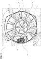
Figure 3 is a front view of the portion of the engine; and -
Figure 4 is a view of an embodiment of the present invention. - In
figure 1 numeral 1 indicates an agricultural vehicle 1 (shown partially) provided with an internal combustion engine(not shown), typically a diesel engine.Vehicle 1 is designed to operate in agricultural environment where organic materials are cultivated, harvested, treated, moved or elaborated. - The combustion engine of known kind is provided with
cooling fan 3 carried by afan shroud 4 provided with a centralcircular aperture 5 to accommodate rotatingfan blades 6. In the example the shroud 4 (of known kind) comprises acylindrical wall 7 that internally defines theaperture 5 and accommodates thefan blades 6 rotating around an axis coaxial with the axis of thecylindrical wall 7. - The agricultural vehicle visible on
figure 1 is provided with a funnel shapedmember 10 having a first end portion 10-a defining an ininlet aperture 12 and a second end portion 10-b with a reduced section with respect to the first end portion 10-a and defining anoutlet aperture 13. - The first end portion 10-a is designed to be connected with a portion of the fan shroud 4 (in the example a rim of the
cylindrical wall 7, bolt or screws may be used) to face theblades 6 so that air blown by thefan blades 6 is supplied to the inlet aperture and air flowing in the funnel shapedmember 10 is accelerated so that a flux of washing accelerated air (indicated by means of an arrow) is provided at theoutlet aperture 13. - The
outlet aperture 13 is placed to face asurface 17 of acomponent 20 of the engine so that the flux ofwashing air 15 sweeps thesurface 17 preventing the accumulation of organic components on thatsurface 17. Thesurface 17 is a surface that is heated during the functioning of the engine. - Accordingly, the
surface 17 is washed constantly and the flux of acceleratedair 15 prevents the accumulation of organic dust, crop, hay, chaff, etc. on thehot surface 17. The risk of fire is thus reduced without the need of providing thesurface 17 with a thermal insulation. The described solution is simple, cheap and cost effective. This solution does not impact with the performances of the engine. Moreover, no specific maintenance is needed. The sweeping ofsurface 17 is obtained by using an energy that is wasted. According to the embodiment of the invention shown infigure 4 the funnel shapedmember 10 is designed so that second end portion 10-b may be displaced with respect the first end portion 10-a in order to have an articulated outlet aperture 13) that may be positioned to facedifferent surfaces - For instance, the funnel
shaped member 10 may comprises rigid end portions and an intermediate deformable bellow-shaped portion 23 to permit the displacement of the second end portion 10-b with respect the first end portion 10-a. - According to another embodiment of the invention the agricultural vehicle may be equipped with a control unit for controlling the rotational velocity of the fan's blades independently from the temperature of the engine, so that the driver may command to force a high rotational speed even if the engine does not need to be cooled with the aim of creating a flux of further accelerated air preventing the accumulation of organic dust, crop, hay, chaff, etc. on the
hot surface 17.
Claims (3)
- Agricultural vehicle (1) provided with an internal combustion engine (2) provided with fan (3) carried by a fan shroud (4) having with an aperture (5) to accommodate rotating fan blades (6),
comprising a funnel shaped member (10) having a first end portion (10-a) defining an in inlet aperture (12) and a second end portion (10-b) with reduced section defining an outlet aperture (13); the first end portion (10-a) being designed to be connected with a portion (7) of the fan shroud (4) to face the blades (6) so that air blown by the fan blades (6) is supplied to the inlet aperture (12) and air flowing in the funnel shaped member (10) is accelerated so that a flux of washing accelerated air (15) is provided at the outlet aperture (13); said outlet aperture (13) being placed to face a surface (17) of a component (20) of the engine so that the flux of washing air (15) sweeps the surface (17) preventing the accumulation of organic components on the surface; said surface (17) is heated during the functioning of the engine, characterized in that the funnel shaped member (10) is designed so that second end portion (10-b) may be displaced with respect the first end portion (10-a) in order to have an articulated outlet aperture (13) that may be positioned to face different surfaces (17,17b). - Agricultural vehicle as claimed in claim 1, wherein the funnel shaped member (10) comprises rigid end portions and an intermediate bellow-shaped portion (23) to permit the displacement of the second end portion (10-b) with respect the first end portion (10-a).
- Agricultural vehicle as claimed in any of the preceding claims, wherein a control unit is provided for controlling the rotational velocity of the fan's blades independently from the temperature of the engine.
Applications Claiming Priority (1)
| Application Number | Priority Date | Filing Date | Title |
|---|---|---|---|
| IT201900006525 | 2019-05-03 |
Publications (2)
| Publication Number | Publication Date |
|---|---|
| EP3733439A1 EP3733439A1 (en) | 2020-11-04 |
| EP3733439B1 true EP3733439B1 (en) | 2022-07-06 |
Family
ID=67384296
Family Applications (1)
| Application Number | Title | Priority Date | Filing Date |
|---|---|---|---|
| EP20172642.9A Active EP3733439B1 (en) | 2019-05-03 | 2020-05-04 | Agricultural vehicle |
Country Status (1)
| Country | Link |
|---|---|
| EP (1) | EP3733439B1 (en) |
Family Cites Families (2)
| Publication number | Priority date | Publication date | Assignee | Title |
|---|---|---|---|---|
| DE69020716T2 (en) * | 1990-02-20 | 1995-11-02 | Ford New Holland Nv | Fire protection device for an agricultural machine. |
| GB9713419D0 (en) * | 1997-06-26 | 1997-08-27 | Ford New Holland Nv | Fire protected agricultural machine |
-
2020
- 2020-05-04 EP EP20172642.9A patent/EP3733439B1/en active Active
Also Published As
| Publication number | Publication date |
|---|---|
| EP3733439A1 (en) | 2020-11-04 |
Similar Documents
| Publication | Publication Date | Title |
|---|---|---|
| US8226353B2 (en) | Ventilation of a downstream cavity of an impeller of a centrifugal compressor | |
| US7484687B2 (en) | Propulsion device | |
| US6282881B1 (en) | Cooling system for a turbomachine speed reducer | |
| US8132755B2 (en) | Engine exhaust system with directional nozzle | |
| US5410992A (en) | Cooling system for automotive engine | |
| US10214247B2 (en) | Work vehicle | |
| US3903960A (en) | Fan shroud entrance structure | |
| EP2067952B1 (en) | Vehicle cooling system | |
| WO2008041964A2 (en) | Infrared suppression system | |
| EP3002432B1 (en) | Gas turbine with a mounting arrangement for an electrical harness | |
| WO2012061447A2 (en) | Diesel particulate filter packaging and method of directing airflow in a skid steer machine | |
| JPS6325199B2 (en) | ||
| US20120103712A1 (en) | Skid steer machine having pivotably mounted cooling system and non-metallic vibration isolator | |
| US8839601B2 (en) | Door for thrust reverser of an aircraft nacelle | |
| EP3733439A1 (en) | Agricultural vehicle | |
| EP2233394B1 (en) | Propeller with thermally protected blades | |
| US6523508B2 (en) | Manually guided implement | |
| CN111742117A (en) | Propulsion unit including lift points provided on thrust reverser cylinder supports | |
| CN1755080A (en) | Nose cones for turbines | |
| US20070231126A1 (en) | System and method for mounting a fan shroud | |
| US8479498B2 (en) | Method of mixing exhaust gas exiting an exhaust stack outlet with cooling air exiting a cooling package outlet including a regeneration control algorithm and machine using same | |
| EP2340992B1 (en) | Method for propeller blade root flow control by airflow through spinner | |
| US6123290A (en) | Helicopters equipped with jet dilution/deflection means for the combustion gases | |
| GB2299158A (en) | Method and apparatus for securing a fan motor and heat exchanger to a structure | |
| US20240229713A1 (en) | Aircraft propulsion system with variable area inlet |
Legal Events
| Date | Code | Title | Description |
|---|---|---|---|
| PUAI | Public reference made under article 153(3) epc to a published international application that has entered the european phase |
Free format text: ORIGINAL CODE: 0009012 |
|
| STAA | Information on the status of an ep patent application or granted ep patent |
Free format text: STATUS: THE APPLICATION HAS BEEN PUBLISHED |
|
| AK | Designated contracting states |
Kind code of ref document: A1 Designated state(s): AL AT BE BG CH CY CZ DE DK EE ES FI FR GB GR HR HU IE IS IT LI LT LU LV MC MK MT NL NO PL PT RO RS SE SI SK SM TR |
|
| AX | Request for extension of the european patent |
Extension state: BA ME |
|
| STAA | Information on the status of an ep patent application or granted ep patent |
Free format text: STATUS: REQUEST FOR EXAMINATION WAS MADE |
|
| 17P | Request for examination filed |
Effective date: 20210504 |
|
| RBV | Designated contracting states (corrected) |
Designated state(s): AL AT BE BG CH CY CZ DE DK EE ES FI FR GB GR HR HU IE IS IT LI LT LU LV MC MK MT NL NO PL PT RO RS SE SI SK SM TR |
|
| GRAP | Despatch of communication of intention to grant a patent |
Free format text: ORIGINAL CODE: EPIDOSNIGR1 |
|
| STAA | Information on the status of an ep patent application or granted ep patent |
Free format text: STATUS: GRANT OF PATENT IS INTENDED |
|
| INTG | Intention to grant announced |
Effective date: 20220131 |
|
| GRAS | Grant fee paid |
Free format text: ORIGINAL CODE: EPIDOSNIGR3 |
|
| GRAA | (expected) grant |
Free format text: ORIGINAL CODE: 0009210 |
|
| STAA | Information on the status of an ep patent application or granted ep patent |
Free format text: STATUS: THE PATENT HAS BEEN GRANTED |
|
| AK | Designated contracting states |
Kind code of ref document: B1 Designated state(s): AL AT BE BG CH CY CZ DE DK EE ES FI FR GB GR HR HU IE IS IT LI LT LU LV MC MK MT NL NO PL PT RO RS SE SI SK SM TR |
|
| REG | Reference to a national code |
Ref country code: AT Ref legal event code: REF Ref document number: 1502638 Country of ref document: AT Kind code of ref document: T Effective date: 20220715 Ref country code: CH Ref legal event code: EP |
|
| REG | Reference to a national code |
Ref country code: DE Ref legal event code: R096 Ref document number: 602020003842 Country of ref document: DE |
|
| REG | Reference to a national code |
Ref country code: IE Ref legal event code: FG4D |
|
| REG | Reference to a national code |
Ref country code: LT Ref legal event code: MG9D |
|
| REG | Reference to a national code |
Ref country code: NL Ref legal event code: MP Effective date: 20220706 |
|
| PG25 | Lapsed in a contracting state [announced via postgrant information from national office to epo] |
Ref country code: SE Free format text: LAPSE BECAUSE OF FAILURE TO SUBMIT A TRANSLATION OF THE DESCRIPTION OR TO PAY THE FEE WITHIN THE PRESCRIBED TIME-LIMIT Effective date: 20220706 Ref country code: RS Free format text: LAPSE BECAUSE OF FAILURE TO SUBMIT A TRANSLATION OF THE DESCRIPTION OR TO PAY THE FEE WITHIN THE PRESCRIBED TIME-LIMIT Effective date: 20220706 Ref country code: PT Free format text: LAPSE BECAUSE OF FAILURE TO SUBMIT A TRANSLATION OF THE DESCRIPTION OR TO PAY THE FEE WITHIN THE PRESCRIBED TIME-LIMIT Effective date: 20221107 Ref country code: NO Free format text: LAPSE BECAUSE OF FAILURE TO SUBMIT A TRANSLATION OF THE DESCRIPTION OR TO PAY THE FEE WITHIN THE PRESCRIBED TIME-LIMIT Effective date: 20221006 Ref country code: NL Free format text: LAPSE BECAUSE OF FAILURE TO SUBMIT A TRANSLATION OF THE DESCRIPTION OR TO PAY THE FEE WITHIN THE PRESCRIBED TIME-LIMIT Effective date: 20220706 Ref country code: LV Free format text: LAPSE BECAUSE OF FAILURE TO SUBMIT A TRANSLATION OF THE DESCRIPTION OR TO PAY THE FEE WITHIN THE PRESCRIBED TIME-LIMIT Effective date: 20220706 Ref country code: LT Free format text: LAPSE BECAUSE OF FAILURE TO SUBMIT A TRANSLATION OF THE DESCRIPTION OR TO PAY THE FEE WITHIN THE PRESCRIBED TIME-LIMIT Effective date: 20220706 Ref country code: FI Free format text: LAPSE BECAUSE OF FAILURE TO SUBMIT A TRANSLATION OF THE DESCRIPTION OR TO PAY THE FEE WITHIN THE PRESCRIBED TIME-LIMIT Effective date: 20220706 Ref country code: ES Free format text: LAPSE BECAUSE OF FAILURE TO SUBMIT A TRANSLATION OF THE DESCRIPTION OR TO PAY THE FEE WITHIN THE PRESCRIBED TIME-LIMIT Effective date: 20220706 |
|
| REG | Reference to a national code |
Ref country code: AT Ref legal event code: MK05 Ref document number: 1502638 Country of ref document: AT Kind code of ref document: T Effective date: 20220706 |
|
| PG25 | Lapsed in a contracting state [announced via postgrant information from national office to epo] |
Ref country code: PL Free format text: LAPSE BECAUSE OF FAILURE TO SUBMIT A TRANSLATION OF THE DESCRIPTION OR TO PAY THE FEE WITHIN THE PRESCRIBED TIME-LIMIT Effective date: 20220706 Ref country code: IS Free format text: LAPSE BECAUSE OF FAILURE TO SUBMIT A TRANSLATION OF THE DESCRIPTION OR TO PAY THE FEE WITHIN THE PRESCRIBED TIME-LIMIT Effective date: 20221106 Ref country code: HR Free format text: LAPSE BECAUSE OF FAILURE TO SUBMIT A TRANSLATION OF THE DESCRIPTION OR TO PAY THE FEE WITHIN THE PRESCRIBED TIME-LIMIT Effective date: 20220706 Ref country code: GR Free format text: LAPSE BECAUSE OF FAILURE TO SUBMIT A TRANSLATION OF THE DESCRIPTION OR TO PAY THE FEE WITHIN THE PRESCRIBED TIME-LIMIT Effective date: 20221007 |
|
| REG | Reference to a national code |
Ref country code: DE Ref legal event code: R097 Ref document number: 602020003842 Country of ref document: DE |
|
| PG25 | Lapsed in a contracting state [announced via postgrant information from national office to epo] |
Ref country code: SM Free format text: LAPSE BECAUSE OF FAILURE TO SUBMIT A TRANSLATION OF THE DESCRIPTION OR TO PAY THE FEE WITHIN THE PRESCRIBED TIME-LIMIT Effective date: 20220706 Ref country code: RO Free format text: LAPSE BECAUSE OF FAILURE TO SUBMIT A TRANSLATION OF THE DESCRIPTION OR TO PAY THE FEE WITHIN THE PRESCRIBED TIME-LIMIT Effective date: 20220706 Ref country code: DK Free format text: LAPSE BECAUSE OF FAILURE TO SUBMIT A TRANSLATION OF THE DESCRIPTION OR TO PAY THE FEE WITHIN THE PRESCRIBED TIME-LIMIT Effective date: 20220706 Ref country code: CZ Free format text: LAPSE BECAUSE OF FAILURE TO SUBMIT A TRANSLATION OF THE DESCRIPTION OR TO PAY THE FEE WITHIN THE PRESCRIBED TIME-LIMIT Effective date: 20220706 Ref country code: AT Free format text: LAPSE BECAUSE OF FAILURE TO SUBMIT A TRANSLATION OF THE DESCRIPTION OR TO PAY THE FEE WITHIN THE PRESCRIBED TIME-LIMIT Effective date: 20220706 |
|
| PLBE | No opposition filed within time limit |
Free format text: ORIGINAL CODE: 0009261 |
|
| STAA | Information on the status of an ep patent application or granted ep patent |
Free format text: STATUS: NO OPPOSITION FILED WITHIN TIME LIMIT |
|
| PG25 | Lapsed in a contracting state [announced via postgrant information from national office to epo] |
Ref country code: SK Free format text: LAPSE BECAUSE OF FAILURE TO SUBMIT A TRANSLATION OF THE DESCRIPTION OR TO PAY THE FEE WITHIN THE PRESCRIBED TIME-LIMIT Effective date: 20220706 Ref country code: EE Free format text: LAPSE BECAUSE OF FAILURE TO SUBMIT A TRANSLATION OF THE DESCRIPTION OR TO PAY THE FEE WITHIN THE PRESCRIBED TIME-LIMIT Effective date: 20220706 |
|
| 26N | No opposition filed |
Effective date: 20230411 |
|
| PG25 | Lapsed in a contracting state [announced via postgrant information from national office to epo] |
Ref country code: AL Free format text: LAPSE BECAUSE OF FAILURE TO SUBMIT A TRANSLATION OF THE DESCRIPTION OR TO PAY THE FEE WITHIN THE PRESCRIBED TIME-LIMIT Effective date: 20220706 |
|
| PG25 | Lapsed in a contracting state [announced via postgrant information from national office to epo] |
Ref country code: SI Free format text: LAPSE BECAUSE OF FAILURE TO SUBMIT A TRANSLATION OF THE DESCRIPTION OR TO PAY THE FEE WITHIN THE PRESCRIBED TIME-LIMIT Effective date: 20220706 |
|
| REG | Reference to a national code |
Ref country code: CH Ref legal event code: PL |
|
| PG25 | Lapsed in a contracting state [announced via postgrant information from national office to epo] |
Ref country code: MC Free format text: LAPSE BECAUSE OF FAILURE TO SUBMIT A TRANSLATION OF THE DESCRIPTION OR TO PAY THE FEE WITHIN THE PRESCRIBED TIME-LIMIT Effective date: 20220706 |
|
| REG | Reference to a national code |
Ref country code: BE Ref legal event code: MM Effective date: 20230531 |
|
| PG25 | Lapsed in a contracting state [announced via postgrant information from national office to epo] |
Ref country code: MC Free format text: LAPSE BECAUSE OF FAILURE TO SUBMIT A TRANSLATION OF THE DESCRIPTION OR TO PAY THE FEE WITHIN THE PRESCRIBED TIME-LIMIT Effective date: 20220706 Ref country code: LU Free format text: LAPSE BECAUSE OF NON-PAYMENT OF DUE FEES Effective date: 20230504 Ref country code: LI Free format text: LAPSE BECAUSE OF NON-PAYMENT OF DUE FEES Effective date: 20230531 Ref country code: CH Free format text: LAPSE BECAUSE OF NON-PAYMENT OF DUE FEES Effective date: 20230531 |
|
| REG | Reference to a national code |
Ref country code: IE Ref legal event code: MM4A |
|
| PG25 | Lapsed in a contracting state [announced via postgrant information from national office to epo] |
Ref country code: IE Free format text: LAPSE BECAUSE OF NON-PAYMENT OF DUE FEES Effective date: 20230504 |
|
| PG25 | Lapsed in a contracting state [announced via postgrant information from national office to epo] |
Ref country code: IE Free format text: LAPSE BECAUSE OF NON-PAYMENT OF DUE FEES Effective date: 20230504 |
|
| PG25 | Lapsed in a contracting state [announced via postgrant information from national office to epo] |
Ref country code: BE Free format text: LAPSE BECAUSE OF NON-PAYMENT OF DUE FEES Effective date: 20230531 |
|
| PG25 | Lapsed in a contracting state [announced via postgrant information from national office to epo] |
Ref country code: BG Free format text: LAPSE BECAUSE OF FAILURE TO SUBMIT A TRANSLATION OF THE DESCRIPTION OR TO PAY THE FEE WITHIN THE PRESCRIBED TIME-LIMIT Effective date: 20220706 |
|
| PG25 | Lapsed in a contracting state [announced via postgrant information from national office to epo] |
Ref country code: BG Free format text: LAPSE BECAUSE OF FAILURE TO SUBMIT A TRANSLATION OF THE DESCRIPTION OR TO PAY THE FEE WITHIN THE PRESCRIBED TIME-LIMIT Effective date: 20220706 |
|
| PGFP | Annual fee paid to national office [announced via postgrant information from national office to epo] |
Ref country code: DE Payment date: 20250528 Year of fee payment: 6 |
|
| PGFP | Annual fee paid to national office [announced via postgrant information from national office to epo] |
Ref country code: GB Payment date: 20250520 Year of fee payment: 6 |
|
| PGFP | Annual fee paid to national office [announced via postgrant information from national office to epo] |
Ref country code: IT Payment date: 20250522 Year of fee payment: 6 |
|
| PGFP | Annual fee paid to national office [announced via postgrant information from national office to epo] |
Ref country code: FR Payment date: 20250526 Year of fee payment: 6 |
|
| PG25 | Lapsed in a contracting state [announced via postgrant information from national office to epo] |
Ref country code: CY Free format text: LAPSE BECAUSE OF FAILURE TO SUBMIT A TRANSLATION OF THE DESCRIPTION OR TO PAY THE FEE WITHIN THE PRESCRIBED TIME-LIMIT; INVALID AB INITIO Effective date: 20200504 |
|
| PG25 | Lapsed in a contracting state [announced via postgrant information from national office to epo] |
Ref country code: HU Free format text: LAPSE BECAUSE OF FAILURE TO SUBMIT A TRANSLATION OF THE DESCRIPTION OR TO PAY THE FEE WITHIN THE PRESCRIBED TIME-LIMIT; INVALID AB INITIO Effective date: 20200504 |
|
| PG25 | Lapsed in a contracting state [announced via postgrant information from national office to epo] |
Ref country code: TR Free format text: LAPSE BECAUSE OF FAILURE TO SUBMIT A TRANSLATION OF THE DESCRIPTION OR TO PAY THE FEE WITHIN THE PRESCRIBED TIME-LIMIT Effective date: 20220706 |