EP3733315A1 - Systems and methods for cleaning pressure pot cover assembly - Google Patents
Systems and methods for cleaning pressure pot cover assembly Download PDFInfo
- Publication number
- EP3733315A1 EP3733315A1 EP20171880.6A EP20171880A EP3733315A1 EP 3733315 A1 EP3733315 A1 EP 3733315A1 EP 20171880 A EP20171880 A EP 20171880A EP 3733315 A1 EP3733315 A1 EP 3733315A1
- Authority
- EP
- European Patent Office
- Prior art keywords
- cover assembly
- cleaning
- pressure pot
- cleaning solution
- wash tank
- Prior art date
- Legal status (The legal status is an assumption and is not a legal conclusion. Google has not performed a legal analysis and makes no representation as to the accuracy of the status listed.)
- Granted
Links
Images


Classifications
-
- B—PERFORMING OPERATIONS; TRANSPORTING
- B08—CLEANING
- B08B—CLEANING IN GENERAL; PREVENTION OF FOULING IN GENERAL
- B08B9/00—Cleaning hollow articles by methods or apparatus specially adapted thereto
- B08B9/02—Cleaning pipes or tubes or systems of pipes or tubes
- B08B9/027—Cleaning the internal surfaces; Removal of blockages
- B08B9/032—Cleaning the internal surfaces; Removal of blockages by the mechanical action of a moving fluid, e.g. by flushing
- B08B9/0321—Cleaning the internal surfaces; Removal of blockages by the mechanical action of a moving fluid, e.g. by flushing using pressurised, pulsating or purging fluid
-
- B—PERFORMING OPERATIONS; TRANSPORTING
- B05—SPRAYING OR ATOMISING IN GENERAL; APPLYING FLUENT MATERIALS TO SURFACES, IN GENERAL
- B05B—SPRAYING APPARATUS; ATOMISING APPARATUS; NOZZLES
- B05B15/00—Details of spraying plant or spraying apparatus not otherwise provided for; Accessories
- B05B15/50—Arrangements for cleaning; Arrangements for preventing deposits, drying-out or blockage; Arrangements for detecting improper discharge caused by the presence of foreign matter
- B05B15/55—Arrangements for cleaning; Arrangements for preventing deposits, drying-out or blockage; Arrangements for detecting improper discharge caused by the presence of foreign matter using cleaning fluids
- B05B15/555—Arrangements for cleaning; Arrangements for preventing deposits, drying-out or blockage; Arrangements for detecting improper discharge caused by the presence of foreign matter using cleaning fluids discharged by cleaning nozzles
-
- B—PERFORMING OPERATIONS; TRANSPORTING
- B08—CLEANING
- B08B—CLEANING IN GENERAL; PREVENTION OF FOULING IN GENERAL
- B08B3/00—Cleaning by methods involving the use or presence of liquid or steam
- B08B3/02—Cleaning by the force of jets or sprays
-
- B—PERFORMING OPERATIONS; TRANSPORTING
- B08—CLEANING
- B08B—CLEANING IN GENERAL; PREVENTION OF FOULING IN GENERAL
- B08B3/00—Cleaning by methods involving the use or presence of liquid or steam
- B08B3/04—Cleaning involving contact with liquid
- B08B3/10—Cleaning involving contact with liquid with additional treatment of the liquid or of the object being cleaned, e.g. by heat, by electricity or by vibration
-
- B—PERFORMING OPERATIONS; TRANSPORTING
- B01—PHYSICAL OR CHEMICAL PROCESSES OR APPARATUS IN GENERAL
- B01F—MIXING, e.g. DISSOLVING, EMULSIFYING OR DISPERSING
- B01F33/00—Other mixers; Mixing plants; Combinations of mixers
- B01F33/86—Mixing heads comprising a driven stirrer
-
- B—PERFORMING OPERATIONS; TRANSPORTING
- B01—PHYSICAL OR CHEMICAL PROCESSES OR APPARATUS IN GENERAL
- B01F—MIXING, e.g. DISSOLVING, EMULSIFYING OR DISPERSING
- B01F35/00—Accessories for mixers; Auxiliary operations or auxiliary devices; Parts or details of general application
- B01F35/10—Maintenance of mixers
- B01F35/145—Washing or cleaning mixers not provided for in other groups in this subclass; Inhibiting build-up of material on machine parts using other means
- B01F35/1452—Washing or cleaning mixers not provided for in other groups in this subclass; Inhibiting build-up of material on machine parts using other means using fluids
- B01F35/1453—Washing or cleaning mixers not provided for in other groups in this subclass; Inhibiting build-up of material on machine parts using other means using fluids by means of jets of fluid, e.g. air
-
- B—PERFORMING OPERATIONS; TRANSPORTING
- B08—CLEANING
- B08B—CLEANING IN GENERAL; PREVENTION OF FOULING IN GENERAL
- B08B2203/00—Details of cleaning machines or methods involving the use or presence of liquid or steam
- B08B2203/02—Details of machines or methods for cleaning by the force of jets or sprays
- B08B2203/0211—Case coverings
-
- B—PERFORMING OPERATIONS; TRANSPORTING
- B08—CLEANING
- B08B—CLEANING IN GENERAL; PREVENTION OF FOULING IN GENERAL
- B08B2209/00—Details of machines or methods for cleaning hollow articles
- B08B2209/02—Details of apparatuses or methods for cleaning pipes or tubes
- B08B2209/027—Details of apparatuses or methods for cleaning pipes or tubes for cleaning the internal surfaces
- B08B2209/032—Details of apparatuses or methods for cleaning pipes or tubes for cleaning the internal surfaces by the mechanical action of a moving fluid
Definitions
- This disclosure relates generally to a system with a pressure pot and systems and methods for cleaning a cover assembly of the pressure pot.
- Material spray systems are used in the art to apply coating materials onto components.
- Some known spray systems are configured with a pressure pot to facilitate, among other things, the mixing of the coating material. After a component is coated, the pressure pot and its components are cleaned to remove residue coating material from its surfaces. This cleaning process is typically a manual cleaning process and, thus, labor intensive and time consuming.
- a cleaning method is provided during which a cover assembly is removed from a pressure pot of a material spray system.
- the cover assembly is mated with a wash tank, where the cover assembly closes an opening into the wash tank.
- Cleaning solution is directed into a cavity of the wash tank and against the cover assembly to remove material residue from the cover assembly.
- a method is provided during which coating material is applied onto a component of a gas turbine engine using a material spray system that includes a pressure pot and a cover assembly for the pressure pot. Subsequent to the applying of the coating, the cover assembly is removed from the pressure pot. The cover assembly is arranged on a wash tank. Residue from the coating material is removed off of the cover assembly using a cleaning solution while the cover assembly is arranged on the wash tank.
- a cleaning system for a pressure pot cover assembly of a material spray system, where the pressure pot cover assembly includes a lid and one or more tools projecting from the lid.
- the cleaning system includes a wash tank and a cleaning assembly.
- the wash tank has an internal cavity and is configured to receive the one or more tools of the pressure pot cover assembly.
- An opening into the internal cavity is configured to be closed by the lid of the pressure pot cover assembly.
- the cleaning assembly is arranged within the internal cavity of the wash tank. The cleaning assembly is configured to direct cleaning solution against the pressure pot cover assembly to remove material residue from the pressure pot cover assembly.
- the cleaning system may also include a supply tank and a reclaim tank.
- the supply tank is fluidly coupled with the cleaning assembly.
- the supply tank is configured to provide the cleaning solution to the cleaning assembly.
- the reclaim tank is fluidly coupled with the internal cavity of the wash tank.
- the reclaim tank is configured to receive the cleaning solution after being directed against the pressure pot cover assembly.
- the cleaning assembly may be configured as or otherwise include a nozzle configured to direct the cleaning solution against a tube of a material pickup device.
- the one or more tools may be or include the material pickup conduit.
- the cleaning assembly may be configured as or otherwise include a jet ring configured to circumscribe and direct the cleaning solution against a mixing device.
- the one or more tools may be or include the mixing device.
- the cleaning assembly may be configured as or otherwise include a jet ring configured to direct the cleaning solution against an underside of a lid of the pressure pot cover assembly.
- the cover assembly may include a lid and a tool.
- the lid When the cover assembly is mated with the wash tank: (A) the lid may close the opening into the wash tank; and/or (B) the tool may project into the cavity of the wash tank from the lid.
- the tool may be configured as or otherwise include a mixing device.
- the tool may be configured as or otherwise include a material pickup device.
- the lid When the cover assembly is mated with the pressure pot: (A) the lid may close and seal an opening into the pressure pot; and/or (B) the tool may project into a cavity of the pressure pot and interact with spray material within the cavity of the pressure pot.
- the directing of the cleaning solution may include directing the cleaning solution into a cavity of the wash tank and against the cover assembly from a nozzle.
- the nozzle may be configured to direct the cleaning solution upwards and against a tube of a material pickup device of the cover assembly.
- the directing of the cleaning solution may include directing the cleaning solution into the cavity of the wash tank and against the cover assembly from a jet ring.
- the jet ring may be configured to circumscribe and direct the cleaning solution against a mixing device of the cover assembly.
- the jet ring may be configured to direct the cleaning solution against an underside of a lid of the cover assembly.
- the jet ring may be disposed within the cavity.
- the jet ring may include a plurality of orifices arranged circumferentially in an annular array.
- the method may also include receiving the cleaning solution from a cleaning solution supply tank.
- the method may also include directing the cleaning solution that was directed against the cover assembly within the wash tank into a cleaning solution reclaim tank.
- the method may also include directing the cleaning solution into a conduit of the cover assembly to remove material residue from within the conduit.
- the material residue may be residue material from applying a coating onto a component of a gas turbine engine using the pressure pot.
- the present disclosure includes systems and methods for cleaning or otherwise involving a material spray system, which may also be referred to as a material application system and/or a coating system.
- An exemplary material spray system 10 is schematically illustrated in FIG. 1 and briefly described below. The present disclosure, however, is not limited to the exemplary material spray system configuration shown in FIG. 1 . Rather, the systems and methods of the present disclosure may be implemented with various different material spray system configurations that utilize a pressure pot cover assembly.
- the material spray system 10 of FIG. 1 includes a pressure pot 12 configured with a pressure pot cover assembly 14.
- the material spray system 10 also includes an applicator 16 such as, but not limited to, a device with one or more nozzles.
- the cover assembly 14 includes a lid 18 and one or more tools 20 and 22.
- the lid 18 is configured to mate with a tank 24 of the pressure pot 12. More particularly, the lid 18 is configured to be placed onto a top end 26 of the pressure pot tank 24 so as to close and seal an opening into the pressure pot tank 24. At least a combination of the lid 18 and the pressure pot tank 24 may thereby collectively form a pressure vessel.
- the one or more tools may include a mixing device 20 and a material pickup device 22.
- the mixing device 20 of FIG. 1 includes a rotatable shaft 28 and a rotatable mixing head 30 such as, but not limited to, a mixing impeller.
- the shaft 28 projects downward into an internal cavity 32 of the pressure pot tank 24 and the pressure pot 12 from an underside 34 of the lid 18 to a distal shaft end 36.
- the mixing head 30 is connected to the shaft 28 at (e.g., on, adjacent or proximate) the distal shaft end 36.
- the mixing head 30 is thereby arranged within the cavity 32 and is operable to mix (e.g., stir) material within the cavity 32 of the pressure pot tank 24.
- Examples of material which may be contained in the pressure pot internal cavity 32 include, but are not limited to, polyurethanes, adhesives, sealants, conversion, lubricant type coatings.
- the material pickup device 22 is configured to provide (e.g., flow and/or direct) the mixed material from within the cavity 32 to the applicator 16.
- the material pickup device 22 of FIG. 1 for example, is fluidly coupled to the applicator 16 through at least an external conduit 38.
- the material pickup device 22 of FIG. 1 includes a length of conduit 40 and a pickup tube 42.
- the conduit 40 projects downward into the cavity 32 from the underside 34 of the lid 18 to a distal conduit end.
- the pickup tube 42 is connected to the conduit 40 at the distal conduit end.
- the specific pickup tube 42 of FIG. 1 is configured as either a straight body or a cupped body, where an opening either straight or into a recess formed by the cupped body faces a bottom 44 of the pressure pot tank 24. This pickup tube 42 is located vertically beneath the mixing head 30.
- the material within the pressure pot cavity 32 is mixed by the mixing device 20.
- This mixed material is directed out of the cavity 32 via the material pickup device 22 and provided to the applicator 16 for application (e.g., spraying) onto at least a portion of a surface of a component 46.
- a component 46 is a component of a gas turbine engine; e.g., air airfoil for a rotor blade (e.g., a fan blade, a compressor blade or a turbine blade) or a stator vane.
- various other gas turbine engine components as well as non-gas turbine engine components may alternatively be coated using the material spray system 10.
- the component 46 may be a platform or a gas path wall (e.g., a liner).
- the pressure pot cover assembly 14 may be cleaned utilizing a cleaning system 48 as illustrated, for example, in FIG. 2 .
- the cleaning system 48 of FIG. 2 is configured to remove (partially or completely) the wet and/or dried residue material from one or more surfaces (e.g., the above described surfaces) of the pressure pot cover assembly 14.
- This cleaning system 48 includes a wash tank 50 and an associated cleaning assembly 52.
- the cleaning system 48 of FIG. 2 also includes a supply tank 54 and/or a reclaim tank 56.
- the wash tank 50 is configured as an open ended container such as a bucket or basin.
- the wash tank 50 includes a tubular sidewall 58 and an endwall 60 that form an internal cavity 62.
- This internal cavity 62 is sized to receive the one or more tools 20 and 22 of the pressure pot cover assembly 14.
- the wash tank 50 is similarly configured to mate with the lid 18 of the pressure pot cover assembly 14. More particularly, as similarly described above with respect to the pressure pot tank 24, the wash tank 50 is configured such that the lid 18 may be placed onto a top end 64 of the wash tank 50 (e.g., contacting a rim 59 of the tubular sidewall 58) so as to close and seal an opening 66 into the wash tank 50. At least a combination of the lid 18 and the wash tank 50 may thereby collectively form a pressure vessel.
- the cleaning assembly 52 is configured to direct cleaning solution into the wash tank cavity 62 and against the pressure pot cover assembly 14 and its surfaces to remove the residue material from the cover assembly 14.
- the cleaning assembly 52 of FIG. 3 for example, includes a (e.g., standalone) spray nozzle 68 and one or more jet rings 70 and 72 (schematically shown).
- the spray nozzle 68 is configured to direct the cleaning solution against the pickup tube 42 of the material pickup device 22.
- the nozzle 68 may also or alternatively be configured to direct the cleaning solution into the recess of the pickup tube 42 as well as into an internal passage of the conduit 40.
- the nozzle 68 for example, is disposed within the wash tank 50 and its cavity 62. This nozzle 68 is aligned with the material pickup device 22 and oriented to direct a jet or spray of the cleaning solution upwards towards the material pickup device 22.
- the nozzle 68 may be mated with the pickup tube 42 so as to flow the cleaning solution through the material pickup device 22; e.g., through internal passage of the conduit 40.
- the first (e.g., lower) jet ring 70 is disposed within the wash tank 50 and its cavity 62.
- the first jet ring 70 circumscribes the mixing device 20 and its head 30 as well as the conduit 40.
- the first jet ring 70 includes one or more orifices 74 (e.g., nozzle orifices) arranged circumferentially in an annular array. Each of these orifices 74 is configured to direct a jet or spray of the cleaning solution radially inwards towards the mixing head 30.
- the second (e.g., upper) jet ring 72 is disposed within the wash tank 50 and its cavity 62.
- the second jet ring 72 circumscribes the shaft 28, mixing head 30 and conduit 40.
- the second jet ring 72 includes one or more orifices 76 (e.g., nozzle orifices) arranged circumferentially in an annular array. Each of these orifices 76 is configured to direct a jet or spray of the cleaning solution radially inwards towards the tool elements 28, 30 and 40 and/or upwards towards the underside 34 of the lid 18.
- the supply tank 54 is configured to store the cleaning solution prior to use in the wash tank 50.
- the supply tank 54 is further configured to provide the stored cleaning solution to the wash tank 50.
- the supply tank 54 of FIG. 2 for example, is fluidly coupled with the cleaning assembly 52 and its components through a supply line 78 and a manifold 80 of the cleaning assembly 52. At least a portion of the supply line 78 is external to the wash tank 50 and the supply tank 54.
- the manifold 80 is arranged within the wash tank cavity 62.
- a pump 82 may be fluidly coupled inline with the supply line 78 to draw the cleaning solution out from the supply tank 54 and pump that solution into the cleaning assembly 52 and, therethrough, the wash tank cavity 62.
- the reclaim tank 56 is configured to receive used cleaning solution from the wash tank 50.
- the term "used cleaning solution” describes cleaning solution that has already been directed against the pressure pot cover assembly 14 by the cleaning assembly 52.
- the reclaim tank 56 of FIG. 2 is fluidly coupled to a sump area of the wash tank 50 through a reclaim line 84 that is external to the wash tank 50 and the reclaim tank 56.
- a pump 86 may be fluidly coupled inline with the reclaim line 84 to draw the used cleaning solution out from the wash tank 50 and pump that solution into the reclaim tank 56.
- the reclaim tank 56 may be further fluidly coupled with the supply tank 54 by a return line 88.
- This return line 88 may enable at least some of the reclaimed cleaning solution to be reused for subsequent cleaning operations.
- the return line 88 may be omitted such that the tanks 54 and 56 are only fluidly coupled through the wash tank 50.
- FIG. 4 is a flow diagram of a method 400 for utilizing a cleaning system such as the cleaning system 48 of FIG. 2 .
- This method 400 is also described utilizing a material spray system such as the material spray system 10 of FIG. 1 .
- the method 400 may also be implemented with alternative cleaning systems and/or material spray systems.
- step 402 coating material is applied to a component 46.
- the material spray system 10 may be used to coat one or more surfaces of the component 46 with the coating material.
- step 404 and subsequent to performance of the application (the step 402) of the coating material the pressure pot cover assembly 14 is removed from the pressure pot 12.
- step 406 the pressure pot cover assembly 14 is mated with the wash tank 50.
- the tools 20 and 22, for example, are inserted into the wash tank cavity 62.
- the lid 18 is placed onto the rim 59 of the tubular sidewall 58 so as to cover and seal the opening 66 in the wash tank 50.
- cleaning solution is directed against the pressure pot cover assembly 14 to remove (completely or partially) wet and/or dried residue coating material.
- the cleaning assembly 52 for example, directs the cleaning solution into the cavity 62 and against the surfaces of the cover assembly elements 18, 20, 22, 28, 30, 40 and/or 42.
- the cleaning solution may remove the residue coating material from the pressure pot cover assembly 14 via the force of impact of the cleaning solution onto the residue coating material and/or via chemically dissolving the residue coating material.
- step 410 used cleaning solution is reclaimed.
- the used cleaning solution for example, is directed out of the wash tank cavity 62 and into the reclaim tank 56. This reclaimed cleaning solution may then be stored within the reclaim tank 56 until a subsequent cleaning operation.
- the used cleaning solution may be recirculated to the supply tank 54 to replenish the cleaning solution contained therein; e.g., via return line 88.
- the used cleaning solution may first be processed (e.g., filtered, tested, etc.) prior to being provided back to the supply tank 54.
Landscapes
- Engineering & Computer Science (AREA)
- Mechanical Engineering (AREA)
- Cleaning By Liquid Or Steam (AREA)
Abstract
Description
- This disclosure relates generally to a system with a pressure pot and systems and methods for cleaning a cover assembly of the pressure pot.
- Material spray systems are used in the art to apply coating materials onto components. Some known spray systems are configured with a pressure pot to facilitate, among other things, the mixing of the coating material. After a component is coated, the pressure pot and its components are cleaned to remove residue coating material from its surfaces. This cleaning process is typically a manual cleaning process and, thus, labor intensive and time consuming. There is a need in the art therefore for methods and systems operable to automate the cleaning process of a pressure pot and, for example, an associated pressure pot cover assembly.
- According to an aspect of the present disclosure, a cleaning method is provided during which a cover assembly is removed from a pressure pot of a material spray system. The cover assembly is mated with a wash tank, where the cover assembly closes an opening into the wash tank. Cleaning solution is directed into a cavity of the wash tank and against the cover assembly to remove material residue from the cover assembly.
- According to another aspect of the present disclosure, a method is provided during which coating material is applied onto a component of a gas turbine engine using a material spray system that includes a pressure pot and a cover assembly for the pressure pot. Subsequent to the applying of the coating, the cover assembly is removed from the pressure pot. The cover assembly is arranged on a wash tank. Residue from the coating material is removed off of the cover assembly using a cleaning solution while the cover assembly is arranged on the wash tank.
- According to still another aspect of the present disclosure, a cleaning system is provided for a pressure pot cover assembly of a material spray system, where the pressure pot cover assembly includes a lid and one or more tools projecting from the lid. The cleaning system includes a wash tank and a cleaning assembly. The wash tank has an internal cavity and is configured to receive the one or more tools of the pressure pot cover assembly. An opening into the internal cavity is configured to be closed by the lid of the pressure pot cover assembly. The cleaning assembly is arranged within the internal cavity of the wash tank. The cleaning assembly is configured to direct cleaning solution against the pressure pot cover assembly to remove material residue from the pressure pot cover assembly.
- The following optional features may be applied to any of the above aspects.
- The cleaning system may also include a supply tank and a reclaim tank. The supply tank is fluidly coupled with the cleaning assembly. The supply tank is configured to provide the cleaning solution to the cleaning assembly. The reclaim tank is fluidly coupled with the internal cavity of the wash tank. The reclaim tank is configured to receive the cleaning solution after being directed against the pressure pot cover assembly.
- The cleaning assembly may be configured as or otherwise include a nozzle configured to direct the cleaning solution against a tube of a material pickup device. The one or more tools may be or include the material pickup conduit.
- The cleaning assembly may be configured as or otherwise include a jet ring configured to circumscribe and direct the cleaning solution against a mixing device. The one or more tools may be or include the mixing device.
- The cleaning assembly may be configured as or otherwise include a jet ring configured to direct the cleaning solution against an underside of a lid of the pressure pot cover assembly.
- The cover assembly may include a lid and a tool. When the cover assembly is mated with the wash tank: (A) the lid may close the opening into the wash tank; and/or (B) the tool may project into the cavity of the wash tank from the lid.
- The tool may be configured as or otherwise include a mixing device.
- The tool may be configured as or otherwise include a material pickup device.
- When the cover assembly is mated with the pressure pot: (A) the lid may close and seal an opening into the pressure pot; and/or (B) the tool may project into a cavity of the pressure pot and interact with spray material within the cavity of the pressure pot.
- The directing of the cleaning solution may include directing the cleaning solution into a cavity of the wash tank and against the cover assembly from a nozzle.
- The nozzle may be configured to direct the cleaning solution upwards and against a tube of a material pickup device of the cover assembly.
- The directing of the cleaning solution may include directing the cleaning solution into the cavity of the wash tank and against the cover assembly from a jet ring.
- The jet ring may be configured to circumscribe and direct the cleaning solution against a mixing device of the cover assembly.
- The jet ring may be configured to direct the cleaning solution against an underside of a lid of the cover assembly.
- The jet ring may be disposed within the cavity. The jet ring may include a plurality of orifices arranged circumferentially in an annular array.
- The method may also include receiving the cleaning solution from a cleaning solution supply tank.
- The method may also include directing the cleaning solution that was directed against the cover assembly within the wash tank into a cleaning solution reclaim tank.
- The method may also include directing the cleaning solution into a conduit of the cover assembly to remove material residue from within the conduit.
- The material residue may be residue material from applying a coating onto a component of a gas turbine engine using the pressure pot.
- The foregoing features and the operation of the invention will become more apparent in light of the following description and the accompanying drawings.
-
-
FIG. 1 is a partial schematic illustration of a material spray system applying coating material onto a component. -
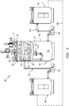
FIG. 2 is a partial schematic illustration of a cleaning system. -
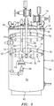
FIG. 3 is a partial schematic illustration of a pressure pot cover assembly mated with a wash tank of the cleaning system. -
FIG. 4 is a flow diagram of a method utilizing a material spray system and a cleaning system. - The present disclosure includes systems and methods for cleaning or otherwise involving a material spray system, which may also be referred to as a material application system and/or a coating system. An exemplary
material spray system 10 is schematically illustrated inFIG. 1 and briefly described below. The present disclosure, however, is not limited to the exemplary material spray system configuration shown inFIG. 1 . Rather, the systems and methods of the present disclosure may be implemented with various different material spray system configurations that utilize a pressure pot cover assembly. - The
material spray system 10 ofFIG. 1 includes apressure pot 12 configured with a pressurepot cover assembly 14. Thematerial spray system 10 also includes anapplicator 16 such as, but not limited to, a device with one or more nozzles. - The
cover assembly 14 includes alid 18 and one ormore tools lid 18 is configured to mate with atank 24 of thepressure pot 12. More particularly, thelid 18 is configured to be placed onto atop end 26 of thepressure pot tank 24 so as to close and seal an opening into thepressure pot tank 24. At least a combination of thelid 18 and thepressure pot tank 24 may thereby collectively form a pressure vessel. - The one or more tools may include a
mixing device 20 and amaterial pickup device 22. The mixingdevice 20 ofFIG. 1 includes arotatable shaft 28 and arotatable mixing head 30 such as, but not limited to, a mixing impeller. Theshaft 28 projects downward into aninternal cavity 32 of thepressure pot tank 24 and thepressure pot 12 from anunderside 34 of thelid 18 to adistal shaft end 36. The mixinghead 30 is connected to theshaft 28 at (e.g., on, adjacent or proximate) thedistal shaft end 36. The mixinghead 30 is thereby arranged within thecavity 32 and is operable to mix (e.g., stir) material within thecavity 32 of thepressure pot tank 24. Examples of material which may be contained in the pressure potinternal cavity 32 include, but are not limited to, polyurethanes, adhesives, sealants, conversion, lubricant type coatings. - The
material pickup device 22 is configured to provide (e.g., flow and/or direct) the mixed material from within thecavity 32 to theapplicator 16. Thematerial pickup device 22 ofFIG. 1 , for example, is fluidly coupled to theapplicator 16 through at least anexternal conduit 38. Thematerial pickup device 22 ofFIG. 1 includes a length ofconduit 40 and apickup tube 42. Theconduit 40 projects downward into thecavity 32 from theunderside 34 of thelid 18 to a distal conduit end. Thepickup tube 42 is connected to theconduit 40 at the distal conduit end. Thespecific pickup tube 42 ofFIG. 1 is configured as either a straight body or a cupped body, where an opening either straight or into a recess formed by the cupped body faces a bottom 44 of thepressure pot tank 24. Thispickup tube 42 is located vertically beneath the mixinghead 30. - During operation of the
material spray system 10, the material within thepressure pot cavity 32 is mixed by the mixingdevice 20. This mixed material is directed out of thecavity 32 via thematerial pickup device 22 and provided to theapplicator 16 for application (e.g., spraying) onto at least a portion of a surface of acomponent 46. An example of thecomponent 46 is a component of a gas turbine engine; e.g., air airfoil for a rotor blade (e.g., a fan blade, a compressor blade or a turbine blade) or a stator vane. Of course, various other gas turbine engine components as well as non-gas turbine engine components may alternatively be coated using thematerial spray system 10. For example, thecomponent 46 may be a platform or a gas path wall (e.g., a liner). - After the coating component process, leftover / remaining coating material is removed from the
pressure pot 12. However, wet and/or dried residue of this coating material may still coat various surfaces of thepressure pot 12. These surfaces include, but are not limited to, (a) a surface on theunderside 34 of thelid 18, (b) exterior surfaces of the mixingdevice 20 and itselements material pickup device 22 and itselements material pickup device 22 and itselements 40 and 42 (e.g., interior conduit and pickup tube surfaces). To prevent this residue material from contaminating subsequent coating processes and/or reducing efficiency / operability of thematerial spray system 10, the pressurepot cover assembly 14 may be cleaned utilizing acleaning system 48 as illustrated, for example, inFIG. 2 . - The
cleaning system 48 ofFIG. 2 is configured to remove (partially or completely) the wet and/or dried residue material from one or more surfaces (e.g., the above described surfaces) of the pressurepot cover assembly 14. Thiscleaning system 48 includes awash tank 50 and an associatedcleaning assembly 52. Thecleaning system 48 ofFIG. 2 also includes asupply tank 54 and/or a reclaimtank 56. - Referring to
FIG. 3 , thewash tank 50 is configured as an open ended container such as a bucket or basin. Thewash tank 50 includes atubular sidewall 58 and anendwall 60 that form aninternal cavity 62. Thisinternal cavity 62 is sized to receive the one ormore tools pot cover assembly 14. Thewash tank 50 is similarly configured to mate with thelid 18 of the pressurepot cover assembly 14. More particularly, as similarly described above with respect to thepressure pot tank 24, thewash tank 50 is configured such that thelid 18 may be placed onto atop end 64 of the wash tank 50 (e.g., contacting arim 59 of the tubular sidewall 58) so as to close and seal anopening 66 into thewash tank 50. At least a combination of thelid 18 and thewash tank 50 may thereby collectively form a pressure vessel. - The cleaning
assembly 52 is configured to direct cleaning solution into thewash tank cavity 62 and against the pressurepot cover assembly 14 and its surfaces to remove the residue material from thecover assembly 14. The cleaningassembly 52 ofFIG. 3 , for example, includes a (e.g., standalone)spray nozzle 68 and one or more jet rings 70 and 72 (schematically shown). - The
spray nozzle 68 is configured to direct the cleaning solution against thepickup tube 42 of thematerial pickup device 22. Thenozzle 68 may also or alternatively be configured to direct the cleaning solution into the recess of thepickup tube 42 as well as into an internal passage of theconduit 40. Thenozzle 68, for example, is disposed within thewash tank 50 and itscavity 62. Thisnozzle 68 is aligned with thematerial pickup device 22 and oriented to direct a jet or spray of the cleaning solution upwards towards thematerial pickup device 22. Of course, in other embodiments, thenozzle 68 may be mated with thepickup tube 42 so as to flow the cleaning solution through thematerial pickup device 22; e.g., through internal passage of theconduit 40. - The first (e.g., lower)
jet ring 70 is disposed within thewash tank 50 and itscavity 62. Thefirst jet ring 70 circumscribes the mixingdevice 20 and itshead 30 as well as theconduit 40. Thefirst jet ring 70 includes one or more orifices 74 (e.g., nozzle orifices) arranged circumferentially in an annular array. Each of theseorifices 74 is configured to direct a jet or spray of the cleaning solution radially inwards towards the mixinghead 30. - The second (e.g., upper)
jet ring 72 is disposed within thewash tank 50 and itscavity 62. Thesecond jet ring 72 circumscribes theshaft 28, mixinghead 30 andconduit 40. Thesecond jet ring 72 includes one or more orifices 76 (e.g., nozzle orifices) arranged circumferentially in an annular array. Each of theseorifices 76 is configured to direct a jet or spray of the cleaning solution radially inwards towards thetool elements underside 34 of thelid 18. - Referring to
FIG. 2 , thesupply tank 54 is configured to store the cleaning solution prior to use in thewash tank 50. Thesupply tank 54 is further configured to provide the stored cleaning solution to thewash tank 50. Thesupply tank 54 ofFIG. 2 , for example, is fluidly coupled with the cleaningassembly 52 and its components through asupply line 78 and amanifold 80 of the cleaningassembly 52. At least a portion of thesupply line 78 is external to thewash tank 50 and thesupply tank 54. The manifold 80 is arranged within thewash tank cavity 62. Apump 82 may be fluidly coupled inline with thesupply line 78 to draw the cleaning solution out from thesupply tank 54 and pump that solution into the cleaningassembly 52 and, therethrough, thewash tank cavity 62. - The reclaim
tank 56 is configured to receive used cleaning solution from thewash tank 50. The term "used cleaning solution" describes cleaning solution that has already been directed against the pressurepot cover assembly 14 by the cleaningassembly 52. The reclaimtank 56 ofFIG. 2 , for example, is fluidly coupled to a sump area of thewash tank 50 through a reclaimline 84 that is external to thewash tank 50 and the reclaimtank 56. Apump 86 may be fluidly coupled inline with the reclaimline 84 to draw the used cleaning solution out from thewash tank 50 and pump that solution into the reclaimtank 56. - In some embodiments, the reclaim
tank 56 may be further fluidly coupled with thesupply tank 54 by areturn line 88. Thisreturn line 88 may enable at least some of the reclaimed cleaning solution to be reused for subsequent cleaning operations. Of course, in other embodiments, thereturn line 88 may be omitted such that thetanks wash tank 50. -
FIG. 4 is a flow diagram of amethod 400 for utilizing a cleaning system such as thecleaning system 48 ofFIG. 2 . Thismethod 400 is also described utilizing a material spray system such as thematerial spray system 10 ofFIG. 1 . Themethod 400, however, may also be implemented with alternative cleaning systems and/or material spray systems. - In
step 402, coating material is applied to acomponent 46. For example, thematerial spray system 10 may be used to coat one or more surfaces of thecomponent 46 with the coating material. - In
step 404 and subsequent to performance of the application (the step 402) of the coating material, the pressurepot cover assembly 14 is removed from thepressure pot 12. - In
step 406, the pressurepot cover assembly 14 is mated with thewash tank 50. Thetools wash tank cavity 62. Thelid 18 is placed onto therim 59 of thetubular sidewall 58 so as to cover and seal theopening 66 in thewash tank 50. - In
step 408, cleaning solution is directed against the pressurepot cover assembly 14 to remove (completely or partially) wet and/or dried residue coating material. The cleaningassembly 52, for example, directs the cleaning solution into thecavity 62 and against the surfaces of thecover assembly elements pot cover assembly 14 via the force of impact of the cleaning solution onto the residue coating material and/or via chemically dissolving the residue coating material. - In step 410, used cleaning solution is reclaimed. The used cleaning solution, for example, is directed out of the
wash tank cavity 62 and into the reclaimtank 56. This reclaimed cleaning solution may then be stored within the reclaimtank 56 until a subsequent cleaning operation. Alternatively, the used cleaning solution may be recirculated to thesupply tank 54 to replenish the cleaning solution contained therein; e.g., viareturn line 88. Of course, the used cleaning solution may first be processed (e.g., filtered, tested, etc.) prior to being provided back to thesupply tank 54. - While various embodiments of the present disclosure have been described, it will be apparent to those of ordinary skill in the art that many more embodiments and implementations are possible within the scope of the disclosure. For example, the present disclosure as described herein includes several aspects and embodiments that include particular features. Although these features may be described individually, it is within the scope of the present disclosure that some or all of these features may be combined with any one of the aspects and remain within the scope of the disclosure. Accordingly, the present disclosure is not to be restricted except in light of the attached claims and their equivalents.
Claims (15)
- A cleaning method, comprising:removing a cover assembly (14) from a pressure pot (12) of a material spray system (10);mating the cover assembly (14) with a wash tank (50), wherein the cover assembly (14) closes an opening (66) into the wash tank (50); anddirecting cleaning solution into a cavity (62) of the wash tank (50) and against the cover assembly (14) to remove material residue from the cover assembly (14).
- The cleaning method of claim 1, wherein
the cover assembly (14) includes a lid (18) and a tool (20, 22); and
when the cover assembly (14) is mated with the wash tank (50):the lid (18) closes the opening (66) into the wash tank (50); andthe tool (20, 22) projects into the cavity (62) of the wash tank (50) from the lid (18). - The cleaning method of claim 2, wherein the tool (20, 22) comprises a mixing device (20) and/or a material pickup device (22).
- The cleaning method of claim 2 or 3, wherein when the cover assembly (14) is mated with the pressure pot (12):the lid (18) closes and seals an opening into the pressure pot (12); andthe tool (20, 22) projects into a cavity (32) of the pressure pot (12) and interacts with spray material within the cavity (32) of the pressure pot (12).
- The cleaning method of any preceding claim, wherein the directing of the cleaning solution comprises directing the cleaning solution into a or the cavity (62) of the wash tank (50) and against the cover assembly (14) from a nozzle (68), and wherein, optionally, the nozzle (68) is configured to direct the cleaning solution upwards and against a tube (42) of a or the material pickup device (22) of the cover assembly (14).
- The cleaning method of any preceding claim, wherein the directing of the cleaning solution comprises directing the cleaning solution into the cavity (62) of the wash tank (50) and against the cover assembly (14) from a jet ring (70, 72).
- The cleaning method of claim 6, wherein the jet ring (70, 72) is configured to:circumscribe and direct the cleaning solution against a or the mixing device (20) of the cover assembly (14); and/ordirect the cleaning solution against an underside of a or the lid (18) of the cover assembly (14).
- The cleaning method of claim 6 or 7, wherein the jet ring (70, 72) is disposed within the cavity (62) of the wash tank (50) and comprises a plurality of orifices (74, 76) arranged circumferentially in an annular array.
- The cleaning method of any preceding claim, further comprising:receiving the cleaning solution from a cleaning solution supply tank (54);directing the cleaning solution that was directed against the cover assembly (14) within the wash tank (50) into a cleaning solution reclaim tank (56); and/ordirecting the cleaning solution into a conduit (38, 40) of the cover assembly (14) to remove material residue from within the conduit (38, 40).
- The cleaning method of any preceding claim, wherein the material residue comprises residue material from applying a coating onto a component (46) of a gas turbine engine using the pressure pot (12).
- A method, comprising:applying coating material onto a component (46) of a gas turbine engine using a material spray system (10) that comprises a pressure pot (12) and a cover assembly (14) for the pressure pot (12);subsequent to the applying of the coating, removing the cover assembly (14) from the pressure pot (12);arranging the cover assembly (14) on a wash tank (50); andremoving residue from the coating material off of the cover assembly (14) using a cleaning solution while the cover assembly (14) is arranged on the wash tank (50).
- A cleaning system for a pressure pot cover assembly of a material spray system, the pressure pot cover assembly (14) comprising a lid (18) and one or more tools (20, 22) projecting from the lid (18), and the cleaning system comprising:a wash tank (50) with an internal cavity (62) configured to receive the one or more tools (20, 22) of the pressure pot cover assembly (14), and an opening (66) into the internal cavity (62) configured to be closed by the lid (18) of the pressure pot cover assembly (14); anda cleaning assembly (52) arranged within the internal cavity (62) of the wash tank (50), the cleaning assembly (52) configured to direct cleaning solution against the pressure pot cover assembly (14) to remove material residue from the pressure pot cover assembly (14).
- The cleaning system of claim 12, wherein
the cleaning assembly (52) comprises a nozzle (68) configured to direct the cleaning solution against a tube (42) of a material pickup device (22); and
the one or more tools comprises the material pickup device (22). - The cleaning system of claim 12 or 13, wherein
the cleaning assembly (52) comprises a jet ring (72) configured to direct the cleaning solution against an underside of a lid (18) of the pressure pot cover assembly (14); and/or
the cleaning assembly (52) comprises a jet ring (70) configured to circumscribe and direct the cleaning solution against a mixing device (20); and
the one or more tools comprises the mixing device (20). - The cleaning system of claim 12, 13 or 14, further comprising:a supply tank (54) fluidly coupled with the cleaning assembly (52), the supply tank (54) configured to provide the cleaning solution to the cleaning assembly (52); anda reclaim tank (56) fluidly coupled with the internal cavity (62) of the wash tank (50), the reclaim tank (56) configured to receive the cleaning solution after being directed against the pressure pot cover assembly (14).
Applications Claiming Priority (1)
| Application Number | Priority Date | Filing Date | Title |
|---|---|---|---|
| US16/403,068 US20200346256A1 (en) | 2019-05-03 | 2019-05-03 | Systems and methods for cleaning pressure pot cover assembly |
Publications (2)
| Publication Number | Publication Date |
|---|---|
| EP3733315A1 true EP3733315A1 (en) | 2020-11-04 |
| EP3733315B1 EP3733315B1 (en) | 2025-01-29 |
Family
ID=70476051
Family Applications (1)
| Application Number | Title | Priority Date | Filing Date |
|---|---|---|---|
| EP20171880.6A Active EP3733315B1 (en) | 2019-05-03 | 2020-04-28 | Systems and methods for cleaning pressure pot cover assembly |
Country Status (2)
| Country | Link |
|---|---|
| US (1) | US20200346256A1 (en) |
| EP (1) | EP3733315B1 (en) |
Families Citing this family (2)
| Publication number | Priority date | Publication date | Assignee | Title |
|---|---|---|---|---|
| USD953480S1 (en) * | 2019-09-05 | 2022-05-31 | Hyung Goo KIM | Portable polyurethane foam dispenser |
| US20240342769A1 (en) * | 2023-04-14 | 2024-10-17 | Monsanto Technology Llc | Automated Cleaning Systems For Seed Treaters And Related Methods |
Citations (7)
| Publication number | Priority date | Publication date | Assignee | Title |
|---|---|---|---|---|
| GB793275A (en) * | 1954-12-31 | 1958-04-16 | Wilhelm Krautzberger | Improvements in and relating to the spraying of paint and the like |
| US4184778A (en) * | 1979-03-12 | 1980-01-22 | Terrels Joseph L | Cup for paint sprayer |
| WO2009024617A1 (en) * | 2007-08-22 | 2009-02-26 | Richard Denk | Method and apparatus for contamination-free loading and emptying |
| US20100149904A1 (en) * | 2008-12-15 | 2010-06-17 | Taku Ohi | Mixing device |
| FR2973681A1 (en) * | 2011-04-11 | 2012-10-12 | Vincent Didelet | Mixing device for mixing food e.g. juice, has mixing tool for mixing food in container i.e. cup, placed on retractable support, where cleaning device for cleaning mixing tool is integrated in mixing device |
| DE102016103968A1 (en) * | 2016-03-04 | 2017-09-07 | Alexander Westphal | Stirrer, in particular jet mixer and stirring device comprising a stirrer |
| WO2018197627A1 (en) * | 2017-04-26 | 2018-11-01 | Dr. Herfeld Gmbh & Co. Kg | Cleaning container for cleaning the mixing head of a mixing machine, and arrangement with a mixing machine and with a cleaning container of this kind |
Family Cites Families (3)
| Publication number | Priority date | Publication date | Assignee | Title |
|---|---|---|---|---|
| US4025363A (en) * | 1976-01-12 | 1977-05-24 | Benito De Santis | Spray equipment cleaner |
| US5213119A (en) * | 1986-03-20 | 1993-05-25 | Safety-Kleen Corporation | Solvent recirculating type spray gun cleaner |
| US5025818A (en) * | 1989-09-06 | 1991-06-25 | Kalar David L | Paint pump cleaning system |
-
2019
- 2019-05-03 US US16/403,068 patent/US20200346256A1/en not_active Abandoned
-
2020
- 2020-04-28 EP EP20171880.6A patent/EP3733315B1/en active Active
Patent Citations (7)
| Publication number | Priority date | Publication date | Assignee | Title |
|---|---|---|---|---|
| GB793275A (en) * | 1954-12-31 | 1958-04-16 | Wilhelm Krautzberger | Improvements in and relating to the spraying of paint and the like |
| US4184778A (en) * | 1979-03-12 | 1980-01-22 | Terrels Joseph L | Cup for paint sprayer |
| WO2009024617A1 (en) * | 2007-08-22 | 2009-02-26 | Richard Denk | Method and apparatus for contamination-free loading and emptying |
| US20100149904A1 (en) * | 2008-12-15 | 2010-06-17 | Taku Ohi | Mixing device |
| FR2973681A1 (en) * | 2011-04-11 | 2012-10-12 | Vincent Didelet | Mixing device for mixing food e.g. juice, has mixing tool for mixing food in container i.e. cup, placed on retractable support, where cleaning device for cleaning mixing tool is integrated in mixing device |
| DE102016103968A1 (en) * | 2016-03-04 | 2017-09-07 | Alexander Westphal | Stirrer, in particular jet mixer and stirring device comprising a stirrer |
| WO2018197627A1 (en) * | 2017-04-26 | 2018-11-01 | Dr. Herfeld Gmbh & Co. Kg | Cleaning container for cleaning the mixing head of a mixing machine, and arrangement with a mixing machine and with a cleaning container of this kind |
Also Published As
| Publication number | Publication date |
|---|---|
| EP3733315B1 (en) | 2025-01-29 |
| US20200346256A1 (en) | 2020-11-05 |
Similar Documents
| Publication | Publication Date | Title |
|---|---|---|
| US12435643B2 (en) | Methods of cleaning a component within a turbine engine | |
| EP3733315B1 (en) | Systems and methods for cleaning pressure pot cover assembly | |
| KR100321331B1 (en) | Coating method for rotary atomizing head type coating device | |
| US5988526A (en) | Combination nozzle and vacuum hood that is self cleaning | |
| US8632639B2 (en) | Mobile cleaning device and method | |
| US9638055B2 (en) | Cooling hole cleaning method | |
| US5524656A (en) | Arrangement for cleaning dispense valves | |
| CN107849979A (en) | The method for repairing and mending of turbo blade | |
| EP2940184A1 (en) | Method for manufacturing rotary machine, method for plating rotary machine, and rotary machine | |
| US20110180109A1 (en) | Pressure flush process for cooled turbine blades | |
| US8317057B2 (en) | Paint roller paint saving pan | |
| US4184778A (en) | Cup for paint sprayer | |
| CN100446868C (en) | Coating machine and its rotary atomizing head | |
| CN107138482A (en) | Coating die head cleaning systems | |
| JPH07171531A (en) | Piping maintenance robot | |
| JP2009034635A (en) | Waste liquid separation apparatus and waste liquid separation method | |
| CN111511477A (en) | Cleaning method of spray gun | |
| CN100579672C (en) | Cleaning device and equipment cleaning method combined with the device | |
| JP6754894B2 (en) | Electrostatic coating equipment | |
| JP2013071049A (en) | Coating apparatus and coating method using the same | |
| KR101915050B1 (en) | Washing apparatus | |
| TWI668364B (en) | Method for repairing turbine blades | |
| CN103747883A (en) | Painting device | |
| JP4395181B2 (en) | Coating machine cleaning liquid recovery device | |
| JP5653875B2 (en) | Painting equipment |
Legal Events
| Date | Code | Title | Description |
|---|---|---|---|
| PUAI | Public reference made under article 153(3) epc to a published international application that has entered the european phase |
Free format text: ORIGINAL CODE: 0009012 |
|
| STAA | Information on the status of an ep patent application or granted ep patent |
Free format text: STATUS: THE APPLICATION HAS BEEN PUBLISHED |
|
| AK | Designated contracting states |
Kind code of ref document: A1 Designated state(s): AL AT BE BG CH CY CZ DE DK EE ES FI FR GB GR HR HU IE IS IT LI LT LU LV MC MK MT NL NO PL PT RO RS SE SI SK SM TR |
|
| AX | Request for extension of the european patent |
Extension state: BA ME |
|
| STAA | Information on the status of an ep patent application or granted ep patent |
Free format text: STATUS: REQUEST FOR EXAMINATION WAS MADE |
|
| 17P | Request for examination filed |
Effective date: 20210504 |
|
| RBV | Designated contracting states (corrected) |
Designated state(s): AL AT BE BG CH CY CZ DE DK EE ES FI FR GB GR HR HU IE IS IT LI LT LU LV MC MK MT NL NO PL PT RO RS SE SI SK SM TR |
|
| STAA | Information on the status of an ep patent application or granted ep patent |
Free format text: STATUS: EXAMINATION IS IN PROGRESS |
|
| 17Q | First examination report despatched |
Effective date: 20221209 |
|
| RAP3 | Party data changed (applicant data changed or rights of an application transferred) |
Owner name: RTX CORPORATION |
|
| GRAP | Despatch of communication of intention to grant a patent |
Free format text: ORIGINAL CODE: EPIDOSNIGR1 |
|
| STAA | Information on the status of an ep patent application or granted ep patent |
Free format text: STATUS: GRANT OF PATENT IS INTENDED |
|
| INTG | Intention to grant announced |
Effective date: 20240830 |
|
| GRAS | Grant fee paid |
Free format text: ORIGINAL CODE: EPIDOSNIGR3 |
|
| GRAA | (expected) grant |
Free format text: ORIGINAL CODE: 0009210 |
|
| STAA | Information on the status of an ep patent application or granted ep patent |
Free format text: STATUS: THE PATENT HAS BEEN GRANTED |
|
| AK | Designated contracting states |
Kind code of ref document: B1 Designated state(s): AL AT BE BG CH CY CZ DE DK EE ES FI FR GB GR HR HU IE IS IT LI LT LU LV MC MK MT NL NO PL PT RO RS SE SI SK SM TR |
|
| REG | Reference to a national code |
Ref country code: GB Ref legal event code: FG4D |
|
| REG | Reference to a national code |
Ref country code: CH Ref legal event code: EP |
|
| REG | Reference to a national code |
Ref country code: DE Ref legal event code: R096 Ref document number: 602020045417 Country of ref document: DE |
|
| REG | Reference to a national code |
Ref country code: IE Ref legal event code: FG4D |
|
| REG | Reference to a national code |
Ref country code: NL Ref legal event code: MP Effective date: 20250129 |
|
| PG25 | Lapsed in a contracting state [announced via postgrant information from national office to epo] |
Ref country code: NL Free format text: LAPSE BECAUSE OF FAILURE TO SUBMIT A TRANSLATION OF THE DESCRIPTION OR TO PAY THE FEE WITHIN THE PRESCRIBED TIME-LIMIT Effective date: 20250129 |
|
| PG25 | Lapsed in a contracting state [announced via postgrant information from national office to epo] |
Ref country code: RS Free format text: LAPSE BECAUSE OF FAILURE TO SUBMIT A TRANSLATION OF THE DESCRIPTION OR TO PAY THE FEE WITHIN THE PRESCRIBED TIME-LIMIT Effective date: 20250429 |
|
| PG25 | Lapsed in a contracting state [announced via postgrant information from national office to epo] |
Ref country code: FI Free format text: LAPSE BECAUSE OF FAILURE TO SUBMIT A TRANSLATION OF THE DESCRIPTION OR TO PAY THE FEE WITHIN THE PRESCRIBED TIME-LIMIT Effective date: 20250129 |
|
| PG25 | Lapsed in a contracting state [announced via postgrant information from national office to epo] |
Ref country code: PL Free format text: LAPSE BECAUSE OF FAILURE TO SUBMIT A TRANSLATION OF THE DESCRIPTION OR TO PAY THE FEE WITHIN THE PRESCRIBED TIME-LIMIT Effective date: 20250129 |
|
| PGFP | Annual fee paid to national office [announced via postgrant information from national office to epo] |
Ref country code: DE Payment date: 20250319 Year of fee payment: 6 |
|
| PG25 | Lapsed in a contracting state [announced via postgrant information from national office to epo] |
Ref country code: ES Free format text: LAPSE BECAUSE OF FAILURE TO SUBMIT A TRANSLATION OF THE DESCRIPTION OR TO PAY THE FEE WITHIN THE PRESCRIBED TIME-LIMIT Effective date: 20250129 |
|
| REG | Reference to a national code |
Ref country code: LT Ref legal event code: MG9D |
|
| PG25 | Lapsed in a contracting state [announced via postgrant information from national office to epo] |
Ref country code: NO Free format text: LAPSE BECAUSE OF FAILURE TO SUBMIT A TRANSLATION OF THE DESCRIPTION OR TO PAY THE FEE WITHIN THE PRESCRIBED TIME-LIMIT Effective date: 20250429 Ref country code: IS Free format text: LAPSE BECAUSE OF FAILURE TO SUBMIT A TRANSLATION OF THE DESCRIPTION OR TO PAY THE FEE WITHIN THE PRESCRIBED TIME-LIMIT Effective date: 20250529 |
|
| REG | Reference to a national code |
Ref country code: AT Ref legal event code: MK05 Ref document number: 1762942 Country of ref document: AT Kind code of ref document: T Effective date: 20250129 |
|
| PG25 | Lapsed in a contracting state [announced via postgrant information from national office to epo] |
Ref country code: HR Free format text: LAPSE BECAUSE OF FAILURE TO SUBMIT A TRANSLATION OF THE DESCRIPTION OR TO PAY THE FEE WITHIN THE PRESCRIBED TIME-LIMIT Effective date: 20250129 |
|
| PG25 | Lapsed in a contracting state [announced via postgrant information from national office to epo] |
Ref country code: PT Free format text: LAPSE BECAUSE OF FAILURE TO SUBMIT A TRANSLATION OF THE DESCRIPTION OR TO PAY THE FEE WITHIN THE PRESCRIBED TIME-LIMIT Effective date: 20250529 Ref country code: LV Free format text: LAPSE BECAUSE OF FAILURE TO SUBMIT A TRANSLATION OF THE DESCRIPTION OR TO PAY THE FEE WITHIN THE PRESCRIBED TIME-LIMIT Effective date: 20250129 |
|
| PG25 | Lapsed in a contracting state [announced via postgrant information from national office to epo] |
Ref country code: BG Free format text: LAPSE BECAUSE OF FAILURE TO SUBMIT A TRANSLATION OF THE DESCRIPTION OR TO PAY THE FEE WITHIN THE PRESCRIBED TIME-LIMIT Effective date: 20250129 Ref country code: GR Free format text: LAPSE BECAUSE OF FAILURE TO SUBMIT A TRANSLATION OF THE DESCRIPTION OR TO PAY THE FEE WITHIN THE PRESCRIBED TIME-LIMIT Effective date: 20250430 |
|
| PG25 | Lapsed in a contracting state [announced via postgrant information from national office to epo] |
Ref country code: AT Free format text: LAPSE BECAUSE OF FAILURE TO SUBMIT A TRANSLATION OF THE DESCRIPTION OR TO PAY THE FEE WITHIN THE PRESCRIBED TIME-LIMIT Effective date: 20250129 |
|
| PG25 | Lapsed in a contracting state [announced via postgrant information from national office to epo] |
Ref country code: SE Free format text: LAPSE BECAUSE OF FAILURE TO SUBMIT A TRANSLATION OF THE DESCRIPTION OR TO PAY THE FEE WITHIN THE PRESCRIBED TIME-LIMIT Effective date: 20250129 |
|
| PG25 | Lapsed in a contracting state [announced via postgrant information from national office to epo] |
Ref country code: SM Free format text: LAPSE BECAUSE OF FAILURE TO SUBMIT A TRANSLATION OF THE DESCRIPTION OR TO PAY THE FEE WITHIN THE PRESCRIBED TIME-LIMIT Effective date: 20250129 |
|
| PG25 | Lapsed in a contracting state [announced via postgrant information from national office to epo] |
Ref country code: DK Free format text: LAPSE BECAUSE OF FAILURE TO SUBMIT A TRANSLATION OF THE DESCRIPTION OR TO PAY THE FEE WITHIN THE PRESCRIBED TIME-LIMIT Effective date: 20250129 |
|
| PG25 | Lapsed in a contracting state [announced via postgrant information from national office to epo] |
Ref country code: IT Free format text: LAPSE BECAUSE OF FAILURE TO SUBMIT A TRANSLATION OF THE DESCRIPTION OR TO PAY THE FEE WITHIN THE PRESCRIBED TIME-LIMIT Effective date: 20250129 |
|
| PG25 | Lapsed in a contracting state [announced via postgrant information from national office to epo] |
Ref country code: EE Free format text: LAPSE BECAUSE OF FAILURE TO SUBMIT A TRANSLATION OF THE DESCRIPTION OR TO PAY THE FEE WITHIN THE PRESCRIBED TIME-LIMIT Effective date: 20250129 Ref country code: CZ Free format text: LAPSE BECAUSE OF FAILURE TO SUBMIT A TRANSLATION OF THE DESCRIPTION OR TO PAY THE FEE WITHIN THE PRESCRIBED TIME-LIMIT Effective date: 20250129 |
|
| PG25 | Lapsed in a contracting state [announced via postgrant information from national office to epo] |
Ref country code: RO Free format text: LAPSE BECAUSE OF FAILURE TO SUBMIT A TRANSLATION OF THE DESCRIPTION OR TO PAY THE FEE WITHIN THE PRESCRIBED TIME-LIMIT Effective date: 20250129 |
|
| PG25 | Lapsed in a contracting state [announced via postgrant information from national office to epo] |
Ref country code: SK Free format text: LAPSE BECAUSE OF FAILURE TO SUBMIT A TRANSLATION OF THE DESCRIPTION OR TO PAY THE FEE WITHIN THE PRESCRIBED TIME-LIMIT Effective date: 20250129 |
|
| REG | Reference to a national code |
Ref country code: DE Ref legal event code: R097 Ref document number: 602020045417 Country of ref document: DE |
|
| REG | Reference to a national code |
Ref country code: CH Ref legal event code: H13 Free format text: ST27 STATUS EVENT CODE: U-0-0-H10-H13 (AS PROVIDED BY THE NATIONAL OFFICE) Effective date: 20251125 |
|
| PLBE | No opposition filed within time limit |
Free format text: ORIGINAL CODE: 0009261 |
|
| STAA | Information on the status of an ep patent application or granted ep patent |
Free format text: STATUS: NO OPPOSITION FILED WITHIN TIME LIMIT |
|
| PG25 | Lapsed in a contracting state [announced via postgrant information from national office to epo] |
Ref country code: LU Free format text: LAPSE BECAUSE OF NON-PAYMENT OF DUE FEES Effective date: 20250428 |
|
| PG25 | Lapsed in a contracting state [announced via postgrant information from national office to epo] |
Ref country code: MC Free format text: LAPSE BECAUSE OF FAILURE TO SUBMIT A TRANSLATION OF THE DESCRIPTION OR TO PAY THE FEE WITHIN THE PRESCRIBED TIME-LIMIT Effective date: 20250129 |
|
| REG | Reference to a national code |
Ref country code: BE Ref legal event code: MM Effective date: 20250430 |
|
| 26N | No opposition filed |
Effective date: 20251030 |
|
| PG25 | Lapsed in a contracting state [announced via postgrant information from national office to epo] |
Ref country code: BE Free format text: LAPSE BECAUSE OF NON-PAYMENT OF DUE FEES Effective date: 20250430 |
|
| PG25 | Lapsed in a contracting state [announced via postgrant information from national office to epo] |
Ref country code: CH Free format text: LAPSE BECAUSE OF NON-PAYMENT OF DUE FEES Effective date: 20250430 |
|
| PGFP | Annual fee paid to national office [announced via postgrant information from national office to epo] |
Ref country code: GB Payment date: 20260319 Year of fee payment: 7 |
|
| PG25 | Lapsed in a contracting state [announced via postgrant information from national office to epo] |
Ref country code: IE Free format text: LAPSE BECAUSE OF NON-PAYMENT OF DUE FEES Effective date: 20250428 |
|
| PGFP | Annual fee paid to national office [announced via postgrant information from national office to epo] |
Ref country code: FR Payment date: 20260320 Year of fee payment: 7 |