EP3733118A1 - Personal care device with separable coupling in drive train - Google Patents
Personal care device with separable coupling in drive train Download PDFInfo
- Publication number
- EP3733118A1 EP3733118A1 EP19172199.2A EP19172199A EP3733118A1 EP 3733118 A1 EP3733118 A1 EP 3733118A1 EP 19172199 A EP19172199 A EP 19172199A EP 3733118 A1 EP3733118 A1 EP 3733118A1
- Authority
- EP
- European Patent Office
- Prior art keywords
- coupling
- personal care
- care device
- accordance
- motion
- Prior art date
- Legal status (The legal status is an assumption and is not a legal conclusion. Google has not performed a legal analysis and makes no representation as to the accuracy of the status listed.)
- Granted
Links
Images

Classifications
-
- F—MECHANICAL ENGINEERING; LIGHTING; HEATING; WEAPONS; BLASTING
- F16—ENGINEERING ELEMENTS AND UNITS; GENERAL MEASURES FOR PRODUCING AND MAINTAINING EFFECTIVE FUNCTIONING OF MACHINES OR INSTALLATIONS; THERMAL INSULATION IN GENERAL
- F16D—COUPLINGS FOR TRANSMITTING ROTATION; CLUTCHES; BRAKES
- F16D3/00—Yielding couplings, i.e. with means permitting movement between the connected parts during the drive
- F16D3/16—Universal joints in which flexibility is produced by means of pivots or sliding or rolling connecting parts
- F16D3/20—Universal joints in which flexibility is produced by means of pivots or sliding or rolling connecting parts one coupling part entering a sleeve of the other coupling part and connected thereto by sliding or rolling members
- F16D3/202—Universal joints in which flexibility is produced by means of pivots or sliding or rolling connecting parts one coupling part entering a sleeve of the other coupling part and connected thereto by sliding or rolling members one coupling part having radially projecting pins, e.g. tripod joints
- F16D3/205—Universal joints in which flexibility is produced by means of pivots or sliding or rolling connecting parts one coupling part entering a sleeve of the other coupling part and connected thereto by sliding or rolling members one coupling part having radially projecting pins, e.g. tripod joints the pins extending radially outwardly from the coupling part
- F16D3/2055—Universal joints in which flexibility is produced by means of pivots or sliding or rolling connecting parts one coupling part entering a sleeve of the other coupling part and connected thereto by sliding or rolling members one coupling part having radially projecting pins, e.g. tripod joints the pins extending radially outwardly from the coupling part having three pins, i.e. true tripod joints
-
- A—HUMAN NECESSITIES
- A45—HAND OR TRAVELLING ARTICLES
- A45D—HAIRDRESSING OR SHAVING EQUIPMENT; EQUIPMENT FOR COSMETICS OR COSMETIC TREATMENTS, e.g. FOR MANICURING OR PEDICURING
- A45D26/00—Hair-singeing apparatus; Apparatus for removing superfluous hair, e.g. tweezers
- A45D26/0023—Hair-singeing apparatus; Apparatus for removing superfluous hair, e.g. tweezers with rotating clamping elements
- A45D26/0033—Hair-singeing apparatus; Apparatus for removing superfluous hair, e.g. tweezers with rotating clamping elements with rollers
- A45D26/0038—Hair-singeing apparatus; Apparatus for removing superfluous hair, e.g. tweezers with rotating clamping elements with rollers power-driven
-
- A—HUMAN NECESSITIES
- A45—HAND OR TRAVELLING ARTICLES
- A45D—HAIRDRESSING OR SHAVING EQUIPMENT; EQUIPMENT FOR COSMETICS OR COSMETIC TREATMENTS, e.g. FOR MANICURING OR PEDICURING
- A45D26/00—Hair-singeing apparatus; Apparatus for removing superfluous hair, e.g. tweezers
- A45D26/0042—Hair-singeing apparatus; Apparatus for removing superfluous hair, e.g. tweezers with flexible members provided with slits opening and closing during use
- A45D26/0047—Hair-singeing apparatus; Apparatus for removing superfluous hair, e.g. tweezers with flexible members provided with slits opening and closing during use with a helicoidal spring
- A45D26/0052—Hair-singeing apparatus; Apparatus for removing superfluous hair, e.g. tweezers with flexible members provided with slits opening and closing during use with a helicoidal spring power-driven
-
- A—HUMAN NECESSITIES
- A45—HAND OR TRAVELLING ARTICLES
- A45D—HAIRDRESSING OR SHAVING EQUIPMENT; EQUIPMENT FOR COSMETICS OR COSMETIC TREATMENTS, e.g. FOR MANICURING OR PEDICURING
- A45D26/00—Hair-singeing apparatus; Apparatus for removing superfluous hair, e.g. tweezers
- A45D26/0066—Tweezers
- A45D26/0071—Tweezers the hair being extracted automatically, i.e. without manual traction by the user
- A45D26/0076—Tweezers the hair being extracted automatically, i.e. without manual traction by the user power-driven
-
- A—HUMAN NECESSITIES
- A46—BRUSHWARE
- A46B—BRUSHES
- A46B13/00—Brushes with driven brush bodies or carriers
- A46B13/02—Brushes with driven brush bodies or carriers power-driven carriers
-
- A—HUMAN NECESSITIES
- A46—BRUSHWARE
- A46B—BRUSHES
- A46B5/00—Brush bodies; Handles integral with brushware
- A46B5/0095—Removable or interchangeable brush heads
-
- A—HUMAN NECESSITIES
- A61—MEDICAL OR VETERINARY SCIENCE; HYGIENE
- A61C—DENTISTRY; APPARATUS OR METHODS FOR ORAL OR DENTAL HYGIENE
- A61C17/00—Devices for cleaning, polishing, rinsing or drying teeth, teeth cavities or prostheses; Saliva removers; Dental appliances for receiving spittle
- A61C17/16—Power-driven cleaning or polishing devices
- A61C17/22—Power-driven cleaning or polishing devices with brushes, cushions, cups, or the like
- A61C17/222—Brush body details, e.g. the shape thereof or connection to handle
-
- B—PERFORMING OPERATIONS; TRANSPORTING
- B25—HAND TOOLS; PORTABLE POWER-DRIVEN TOOLS; MANIPULATORS
- B25F—COMBINATION OR MULTI-PURPOSE TOOLS NOT OTHERWISE PROVIDED FOR; DETAILS OR COMPONENTS OF PORTABLE POWER-DRIVEN TOOLS NOT PARTICULARLY RELATED TO THE OPERATIONS PERFORMED AND NOT OTHERWISE PROVIDED FOR
- B25F5/00—Details or components of portable power-driven tools not particularly related to the operations performed and not otherwise provided for
- B25F5/001—Gearings, speed selectors, clutches or the like specially adapted for rotary tools
-
- H—ELECTRICITY
- H04—ELECTRIC COMMUNICATION TECHNIQUE
- H04L—TRANSMISSION OF DIGITAL INFORMATION, e.g. TELEGRAPHIC COMMUNICATION
- H04L63/00—Network architectures or network communication protocols for network security
- H04L63/08—Network architectures or network communication protocols for network security for authentication of entities
-
- A—HUMAN NECESSITIES
- A46—BRUSHWARE
- A46B—BRUSHES
- A46B2200/00—Brushes characterized by their functions, uses or applications
- A46B2200/10—For human or animal care
- A46B2200/1006—Brushes for cleaning the hand or the human body
-
- A—HUMAN NECESSITIES
- A46—BRUSHWARE
- A46B—BRUSHES
- A46B2200/00—Brushes characterized by their functions, uses or applications
- A46B2200/10—For human or animal care
- A46B2200/102—Brush specifically designed for massaging the skin or scalp
-
- F—MECHANICAL ENGINEERING; LIGHTING; HEATING; WEAPONS; BLASTING
- F16—ENGINEERING ELEMENTS AND UNITS; GENERAL MEASURES FOR PRODUCING AND MAINTAINING EFFECTIVE FUNCTIONING OF MACHINES OR INSTALLATIONS; THERMAL INSULATION IN GENERAL
- F16D—COUPLINGS FOR TRANSMITTING ROTATION; CLUTCHES; BRAKES
- F16D2200/00—Materials; Production methods therefor
- F16D2200/0034—Materials; Production methods therefor non-metallic
Definitions
- the present disclosure is concerned with a personal care device that has a drive train for coupling a drive unit with a driven treatment head, where the drive train has a separable coupling.
- a personal care device may comprise a handle portion and a head portion that can be detached from the handle portion, e.g. for cleaning purposes or for replacement.
- the head portion comprises a driven treatment head
- the separable coupling may then, e.g., comprise two gear wheels that have gear teeth that are in engagement with each other in the attached state and that become disengaged once the head portion and the handle portion are separated from each other.
- a personal care device having a head portion having a driven treatment head, a handle portion having a drive unit for providing a motion having a motion direction, and a drive train extending between the drive unit and the driven treatment head for transmitting the motion from the drive unit to the driven treatment head, the drive train having a separable coupling, the separable coupling has a first coupling part having a first coupling element, a second coupling part having a second coupling element, the first and the second coupling elements being separably engaged with each other, and a resilient element biasing the first coupling element and the second coupling element against each other so that the first and second coupling elements are engaged in a gap-free manner along the motion direction.
- personal care shall mean the nurture (or care) of the skin and of its adnexa (i.e. hairs and nails) and of the teeth and the oral cavity (including the tongue, the gums etc.), where the aim is on the one hand the prevention of illnesses and the maintenance and strengthening of health (“care”) and on the other hand the cosmetic treatment and improvement of the appearance of the skin and its adnexa or of the teeth and the oral cavity. It shall include the maintenance and strengthening of wellbeing. This includes skin care, hair care, and oral care as well as nail care. This further includes grooming activities such as beard care, shaving, and depilation.
- a "personal care device” thus means any device for performing such nurturing or grooming activity, e.g.
- (cosmetic) skin treatment devices such as skin massage devices or skin brushes; wet razors; electric shavers or trimmers; electric epilators; and oral care devices such as manual or electric toothbrushes, (electric) flossers, (electric) irrigators, (electric) tongue cleaners, or (electric) gum massagers.
- the drive train of the proposed personal care device comprises a separable coupling, which separable coupling comprises a first coupling part and a second coupling part.
- the first coupling part comprises a first coupling element
- the second coupling part comprises a second coupling element.
- the first coupling element and the second coupling element are engaged with each other in the attached state to enable the transfer of motion from the first coupling part to the second coupling part or vice versa.
- the separable coupling further comprises a resilient element that biases the first coupling element and the second coupling element against each other and by this biasing it is as well assured that the two coupling elements are engaged with each other in a gap-free manner, in particular in a motion direction of the motion that shall be transferred from the drive unit to the driven treatment head.
- the two coupling elements can essentially not decouple from each other during operation. Such decoupling may otherwise generate noise (as the coupling elements will eventually bump against each other) and may also lead to wear of the two engaged coupling elements.
- the first and the second coupling element interact by abutting force transmission surfaces that are provided at parts of the first and second coupling elements that are essentially not resilient.
- the resilient element is arranged elsewhere, but not in motion direction (but see below for the arrangement of two resilient elements).
- the resilient element may be arranged in reverse motion direction.
- the force transmission surfaces are disposed at sides of the first and second coupling elements that are not resilient by design. This shall enable a good power transfer and energy is not consumed by a deflection of the parts at which the force transmission surfaces are provided.
- the resilient properties of the parts at which the force transmission surface are arranged shall be less than the resilient properties of the resilient element.
- the spring constant of the parts at which the force transmission surfaces are realized is at least about a factor of two higher than a spring constant of the resilient element.
- the resilient element may be designed so that the applied biasing force is higher than the usual forces that occur during regular operation of the personal care device in reverse motion direction. Forces higher than the biasing force and acting in reverse motion direction would deflect the spring element and thus will lead to a decoupling of the first and second coupling elements.
- the biasing force may thus be defined by measuring the typical forces occurring during regular operation of the personal care device and by setting a threshold so that in average only during 50% or less of the treatment period a decoupling of the first and second coupling elements occurs, or for 25% or less or for 10% or less or for 5% or less or for 4 %, 3%, 2%, or 1% or less.
- the first and second coupling parts comprise further engaging pairs of coupling elements, e.g. at least a second pair of coupling elements.
- the separable coupling may have three or four or more pairs of engaging coupling elements.
- a second resilient element may be provided, which second resilient element may then be disposed in motion direction so that the coupling elements of the second pair of coupling elements are biased against each other and interact at force transmission surfaces that are disposed in the reverse motion direction. This allows that the motion direction may be reversed without losing the effect of the motion transfer via essentially not resilient force transmission surfaces.
- the motion that is transferred from the drive unit to the driven treatment head may be a rotary motion.
- the rotary motion may be an oscillating rotary motion, or the personal care device may comprise the possibility to revert the rotary motion, e.g. by means of a respective input device such as a button or a touch screen. It shall also not be excluded that the motion is a linear motion or a more complex motion.
- the first coupling element is one of a receiving portion (also named: receptacle) and a projection (e.g. a pin) and the second coupling element is the other one of the receiving portion and the projection.
- the receptacle may have an open end in a direction along which the first and second coupling parts are intended to be separated.
- the open end may have a chamfer to accommodate an easy attachment of the separated coupling parts in which the projection will be guided into the receiving portion despite an offset between the two coupling elements due to the chamfer.
- the resilient element may be arranged integral with one of the first or second coupling parts, e.g. it may form one side of the receiving portion in above mentioned example.
- the resilient element may comprise a spring arm that can deflect from a rest position into a deflected position in the coupled state.
- the first coupling element is realized as a receptacle and the second coupling element is realized as a projection engaging with the receptacle when the coupling parts are attached.
- One side of the receptacle may then be realized by the resilient element, e.g. a spring arm that can deflect into a hollow.
- the receptacle may now be designed smaller than the corresponding size of the projection that enters the receptacle.
- the larger sized projection then deflects the spring arm of the resilient element from its rest state into a deflected state. Under such deflection, the resilient element provides a biasing force that pushes the two coupling elements against each other.
- the resilient element may in particular be arranged in a direction opposite to the motion direction so that during operation the two coupling elements transmit the motion via two force transmitting surfaces that are not resilient (ignoring any resiliency of the bulk material from which the coupling elements are made) as was already discussed.
- the resilient element may be made from the same material as the coupling part at which it is integrally provided.
- the material may be a plastic material such a polyoxymethylene, which shall not exclude any other material.
- at least a portion of the resilient element is made from metal, e.g. from spring metal forming for example a spring sheet that may be at least partly overmolded by plastic.
- the treatment head and the handle portion of the personal care device may be arranged to be pivotable with respect to each other around at least one pivot axis.
- the separable coupling may be realized as a separable universal joint.
- the pivot angle may have an absolute range in the order of 1 degree to 50 degrees.
- the handle portion and the treatment head may also be arranged to be pivotable to each other around two in particular perpendicular pivot axes.
- the handle portion and the head portion may be secured to each other by means of at least one pair of separable mechanical connector elements such as a snap hook and a corresponding receptacle for receiving the snap hook.
- Fig. 1A is a schematic depiction of an example personal care device 1 in accordance with the present disclosure.
- the personal care device 1 has a head portion 10 and a handle portion 20 that are separably connected with each other.
- the head portion 10 comprises a treatment head 11, which treatment head 11 has at least one part that is arranged for being driven into motion (for simplification it is in the following said that the treatment head 11 is driven during operation of the personal care device, which shall be understood that at least one part of the treatment head 11 is driven, which shall not exclude that the complete treatment head 11 is driven into motion).
- a drive unit 30 is disposed in the handle portion 20.
- a drive train 40 extends between the drive unit 30 and the treatment head 11 to transmit a motion provided by the drive unit 30 to the treatment head 11.
- the drive train 40 comprises a separable coupling 50 arranged so that when the head portion 10 and the handle portion 20 are separated, also the separable coupling 50 becomes separated.
- the head portion 10 and the handle portion 20 may comprise at least one pair of mechanical connector elements 12, 22.
- the head portion 10 may comprise a mechanical connector element 12 and the handle portion 20 may comprise a mechanical connector element 22, which pair of mechanical connector elements 12, 22 is mechanically connecting the head portion 10 and the handle portion 20 together.
- the head portion 10 and the handle portion 20 comprise two or more pairs of mechanical connector elements.
- One of the mechanical connector elements 12, 22 may be arranged as a snap hook and the other one as a receptacle for receiving at least a portion of the snap hook, e.g. a nose of the snap hook. This shall not exclude hat other mechanical connector elements may be used.
- the separable coupling 50 has a first coupling part 510 and a second coupling part 520 that are separably engaged with each other as will be explained in detail with respect to Fig. 1B .
- the separable coupling 50 further comprises a resilient element 530.
- Fig. 1B is a magnification of the separable coupling 50 shown in Fig. 1A .
- the first coupling part 510 comprises a first coupling element 511A and the second coupling part 520 comprises a second coupling element 512A.
- the coupling 50 can be separated by moving the first coupling part 510 relative to the second coupling part 520 in a separation direction S1 or vice versa moving the second coupling part 520 relative to the first coupling part 510 in a separation direction S2.
- the resilient element 530 is realized as an element being integral with the first coupling part 510. This is to be understood as a non-limiting example and the resilient element 530 might also be arranged at the second coupling part 520 or may otherwise form part of the separable coupling 50.
- the resilient element 530 comprises a spring arm 531 that is in a deflected position (a hollow 532 is provided behind the spring arm 531 so that the spring arm 531 has enough place to deflect). The spring arm 531 thus applies a biasing force F onto the second coupling element 521A and thereby pushes a force transmission surface 522A of the second coupling element 521A against a force transmission surface 512A of the first coupling element 511A.
- the spring arm 531 of the resilient element 530 will move back into its rest position when the first coupling part 510 and the second coupling part 520 become disengaged (i.e. separated).
- the resilient element 530 By means of the resilient element 530, the first coupling element 511A and the second coupling element 521A are engaged in a gap-free manner with respect to the motion direction of the motion M1. Due to the gap-free engagement and due to the biasing force F, the first and second coupling elements 511A, 521A will essentially always be in force transmission contact at their force transmission surfaces 512A, 522A.
- the resilient element 530 may be arranged so that the biasing force is larger than typical forces that might be applied by the second coupling element 522A at the spring arm 531.
- the drive train 40 may comprise an overload clutch so that the forces applied at the resilient element 530 are limited.
- the separable coupling 50 may have more than one pair of coupling elements 511A, 521A.
- Two further pin-like coupling elements 521B and 521C are shown that are in engagement with respective receptacle-like coupling elements provided at the first coupling part 510.
- the relative position between the first coupling part 510 and the second coupling part 520 is defined by the first pair of coupling elements 511A, 521A, any other pair of coupling elements does not need to be engaged in a gap-free manner.
- a second resilient element may be present and this second resilient element may be arranged together with a second pair of coupling elements in a manner mirrored with respect to the motion direction of motion M1 to the shown arrangement of resilient element 530 and first pair of coupling elements 511A and 521A. Such a mirrored arrangement would then take over the force transmission in the inverse motion direction of a motion M1'. In case only the shown arrangement of the resilient element 530 and of the first pair of coupling elements 511A and 521A is present, some energy would get lost due to the elasticity of the resilient element 530 when the motion direction is inverted to M1'.
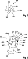
- Fig. 2 is a schematic and perspective depiction of an example coupling part 300 that may be utilized as first or second coupling part of a separable coupling in accordance with the present disclosure.
- the coupling part 300 is arranged at the end of a shaft 310 and comprises a base element 320 and three projections 321, 322, and 323 that are each realized as a pin extend radially outwards from the base element 320 with an angular offset of 180 degrees between each pair of neighboring projections 321 and 322, 322 and 323, and 323 and 321.
- the projections 321, 322, and 323 (i.e. their center lines) extend in a plane that is perpendicular to the longitudinal axis along which the shaft 310 extends.
- one coupling part has one projection that is engaged with a receiving portion of the other coupling part of the separable coupling.
- the respective coupling part may have two projections or four projections etc.
- the coupling element provided as a projection may take any form and is not limited to a pin. In case of two or more coupling elements realized as projections, each of the coupling elements may have its own shape and position.
- Fig. 3 is a schematic and perspective depiction of an example coupling part 400 that may be utilized as first or second coupling part of a separable coupling in accordance with the present disclosure.
- the coupling part 400 may be engaged with the coupling part 300 shown in Fig. 2 to form a separable coupling.
- the coupling part 400 is arranged at the end of a shaft 410 and comprises a base element 420 and three receiving portions 421, 422, and 423 and also a resilient element 430.
- Each of the receiving portions 421, 422, and 423 is formed by the base element 420 and walls of neighboring wall elements 421A, 422A, 423A and in case of the receiving portion 421, one of the walls is defined by a wall of a spring arm 431 of the resilient element 430.
- the wall elements 421A, 422A and 423A each generally extend in a direction that is parallel to the longitudinal extension direction of the shaft element 410.
- a projection engaging with receiving portion 421 has a size that is slightly larger in circumferential direction than the open width of the receiving portion 421 and that the projection bends the spring arm 431 of the resilient element 430 from its shown rest position into a deflected position in which the spring arm 431 is moved into the hollow 432 and biases the projection against the force transmission surface 421F.
- the projection e.g. projection 321 as shown in Fig. 2
- the receiving portion 421 are engaged in a gap-free manner in circumferential direction (i.e. in the direction of the motion M3) and any noise and wear due to repeated decoupling of projection and receiving portion during operation are effectively reduced.
- each coupling part may have a mix of projections and receiving portions, e.g. each coupling part may have one projection and one receiving portion.
- the dimensions and values disclosed herein are not to be understood as being strictly limited to the exact numerical values recited. Instead, unless otherwise specified, each such dimension is intended to mean both the recited value and a functionally equivalent range surrounding that value. For example, a dimension disclosed as "40 mm” is intended to mean "about 40 mm.”
Landscapes
- Engineering & Computer Science (AREA)
- Health & Medical Sciences (AREA)
- General Engineering & Computer Science (AREA)
- Mechanical Engineering (AREA)
- Animal Behavior & Ethology (AREA)
- General Health & Medical Sciences (AREA)
- Public Health (AREA)
- Veterinary Medicine (AREA)
- Life Sciences & Earth Sciences (AREA)
- Epidemiology (AREA)
- Dentistry (AREA)
- Computer Hardware Design (AREA)
- Computer Security & Cryptography (AREA)
- Computing Systems (AREA)
- Computer Networks & Wireless Communication (AREA)
- Signal Processing (AREA)
- Percussion Or Vibration Massage (AREA)
- Brushes (AREA)
- Measurement Of The Respiration, Hearing Ability, Form, And Blood Characteristics Of Living Organisms (AREA)
Abstract
Description
- The present disclosure is concerned with a personal care device that has a drive train for coupling a drive unit with a driven treatment head, where the drive train has a separable coupling.
- It is generally known that a personal care device may comprise a handle portion and a head portion that can be detached from the handle portion, e.g. for cleaning purposes or for replacement. In case the head portion comprises a driven treatment head, this requires that the drive train between a drive unit in the handle portion and the driven treatment head in the head portion must be separable. The separable coupling may then, e.g., comprise two gear wheels that have gear teeth that are in engagement with each other in the attached state and that become disengaged once the head portion and the handle portion are separated from each other.
- It is a general object to improve personal care devices of the described type, in particular with respect to their noise behavior and/or the wear of the separable coupling parts.
- In accordance with an aspect, a personal care device is provided having a head portion having a driven treatment head, a handle portion having a drive unit for providing a motion having a motion direction, and a drive train extending between the drive unit and the driven treatment head for transmitting the motion from the drive unit to the driven treatment head, the drive train having a separable coupling, the separable coupling has a first coupling part having a first coupling element, a second coupling part having a second coupling element, the first and the second coupling elements being separably engaged with each other, and a resilient element biasing the first coupling element and the second coupling element against each other so that the first and second coupling elements are engaged in a gap-free manner along the motion direction.
- The present disclosure and the proposed personal care device will be further elucidated by a detailed description with reference to figures. In the figures
- Fig. 1A
- is a schematic depiction of an example personal care device in accordance with the present disclosure;
- Fig. 1B
- is a magnification of the separable coupling shown in
Fig. 1A ; - Fig. 2
- is a schematic and isolated perspective view of one example coupling part of a separable coupling in accordance with the present disclosure; and
- Fig. 3
- is a schematic and isolated perspective view of another example coupling part of a separable coupling in accordance with the present disclosure.
- In the context of the present description "personal care" shall mean the nurture (or care) of the skin and of its adnexa (i.e. hairs and nails) and of the teeth and the oral cavity (including the tongue, the gums etc.), where the aim is on the one hand the prevention of illnesses and the maintenance and strengthening of health ("care") and on the other hand the cosmetic treatment and improvement of the appearance of the skin and its adnexa or of the teeth and the oral cavity. It shall include the maintenance and strengthening of wellbeing. This includes skin care, hair care, and oral care as well as nail care. This further includes grooming activities such as beard care, shaving, and depilation. A "personal care device" thus means any device for performing such nurturing or grooming activity, e.g. (cosmetic) skin treatment devices such as skin massage devices or skin brushes; wet razors; electric shavers or trimmers; electric epilators; and oral care devices such as manual or electric toothbrushes, (electric) flossers, (electric) irrigators, (electric) tongue cleaners, or (electric) gum massagers. This shall not exclude that the proposed personal care system may have a more pronounced benefit in one or several of these nurturing or device areas than in one or several other of these areas.
- In accordance with the present description, the drive train of the proposed personal care device comprises a separable coupling, which separable coupling comprises a first coupling part and a second coupling part. The first coupling part comprises a first coupling element and the second coupling part comprises a second coupling element. The first coupling element and the second coupling element are engaged with each other in the attached state to enable the transfer of motion from the first coupling part to the second coupling part or vice versa. The separable coupling further comprises a resilient element that biases the first coupling element and the second coupling element against each other and by this biasing it is as well assured that the two coupling elements are engaged with each other in a gap-free manner, in particular in a motion direction of the motion that shall be transferred from the drive unit to the driven treatment head. As there is no gap between the coupling elements, the two coupling elements can essentially not decouple from each other during operation. Such decoupling may otherwise generate noise (as the coupling elements will eventually bump against each other) and may also lead to wear of the two engaged coupling elements. In the motion direction, the first and the second coupling element interact by abutting force transmission surfaces that are provided at parts of the first and second coupling elements that are essentially not resilient. That means that the resilient element is arranged elsewhere, but not in motion direction (but see below for the arrangement of two resilient elements). The resilient element may be arranged in reverse motion direction. The force transmission surfaces are disposed at sides of the first and second coupling elements that are not resilient by design. This shall enable a good power transfer and energy is not consumed by a deflection of the parts at which the force transmission surfaces are provided. As all materials have a certain resiliency, the resilient properties of the parts at which the force transmission surface are arranged shall be less than the resilient properties of the resilient element. Expressed by a spring constant, the spring constant of the parts at which the force transmission surfaces are realized is at least about a factor of two higher than a spring constant of the resilient element.
- The resilient element may be designed so that the applied biasing force is higher than the usual forces that occur during regular operation of the personal care device in reverse motion direction. Forces higher than the biasing force and acting in reverse motion direction would deflect the spring element and thus will lead to a decoupling of the first and second coupling elements. The biasing force may thus be defined by measuring the typical forces occurring during regular operation of the personal care device and by setting a threshold so that in average only during 50% or less of the treatment period a decoupling of the first and second coupling elements occurs, or for 25% or less or for 10% or less or for 5% or less or for 4 %, 3%, 2%, or 1% or less.
- In at least one embodiment, the first and second coupling parts comprise further engaging pairs of coupling elements, e.g. at least a second pair of coupling elements. The separable coupling may have three or four or more pairs of engaging coupling elements. In such an embodiment, a second resilient element may be provided, which second resilient element may then be disposed in motion direction so that the coupling elements of the second pair of coupling elements are biased against each other and interact at force transmission surfaces that are disposed in the reverse motion direction. This allows that the motion direction may be reversed without losing the effect of the motion transfer via essentially not resilient force transmission surfaces.
- The motion that is transferred from the drive unit to the driven treatment head may be a rotary motion. In some embodiments, the rotary motion may be an oscillating rotary motion, or the personal care device may comprise the possibility to revert the rotary motion, e.g. by means of a respective input device such as a button or a touch screen. It shall also not be excluded that the motion is a linear motion or a more complex motion.
- In at least one embodiment, the first coupling element is one of a receiving portion (also named: receptacle) and a projection (e.g. a pin) and the second coupling element is the other one of the receiving portion and the projection. The receptacle may have an open end in a direction along which the first and second coupling parts are intended to be separated. The open end may have a chamfer to accommodate an easy attachment of the separated coupling parts in which the projection will be guided into the receiving portion despite an offset between the two coupling elements due to the chamfer.
- The resilient element may be arranged integral with one of the first or second coupling parts, e.g. it may form one side of the receiving portion in above mentioned example. The resilient element may comprise a spring arm that can deflect from a rest position into a deflected position in the coupled state. E.g. the first coupling element is realized as a receptacle and the second coupling element is realized as a projection engaging with the receptacle when the coupling parts are attached. One side of the receptacle may then be realized by the resilient element, e.g. a spring arm that can deflect into a hollow. The receptacle may now be designed smaller than the corresponding size of the projection that enters the receptacle. The larger sized projection then deflects the spring arm of the resilient element from its rest state into a deflected state. Under such deflection, the resilient element provides a biasing force that pushes the two coupling elements against each other. The resilient element may in particular be arranged in a direction opposite to the motion direction so that during operation the two coupling elements transmit the motion via two force transmitting surfaces that are not resilient (ignoring any resiliency of the bulk material from which the coupling elements are made) as was already discussed. The resilient element may be made from the same material as the coupling part at which it is integrally provided. The material may be a plastic material such a polyoxymethylene, which shall not exclude any other material. In some embodiments, at least a portion of the resilient element is made from metal, e.g. from spring metal forming for example a spring sheet that may be at least partly overmolded by plastic.
- The treatment head and the handle portion of the personal care device may be arranged to be pivotable with respect to each other around at least one pivot axis. In order to accommodate such a relative pivoting motion of the first and second coupling parts, the separable coupling may be realized as a separable universal joint. The pivot angle may have an absolute range in the order of 1 degree to 50 degrees. The handle portion and the treatment head may also be arranged to be pivotable to each other around two in particular perpendicular pivot axes.
- The handle portion and the head portion may be secured to each other by means of at least one pair of separable mechanical connector elements such as a snap hook and a corresponding receptacle for receiving the snap hook.
-
Fig. 1A is a schematic depiction of an examplepersonal care device 1 in accordance with the present disclosure. Thepersonal care device 1 has ahead portion 10 and ahandle portion 20 that are separably connected with each other. Thehead portion 10 comprises a treatment head 11, which treatment head 11 has at least one part that is arranged for being driven into motion (for simplification it is in the following said that the treatment head 11 is driven during operation of the personal care device, which shall be understood that at least one part of the treatment head 11 is driven, which shall not exclude that the complete treatment head 11 is driven into motion). Adrive unit 30 is disposed in thehandle portion 20. Adrive train 40 extends between thedrive unit 30 and the treatment head 11 to transmit a motion provided by thedrive unit 30 to the treatment head 11. Thedrive train 40 comprises aseparable coupling 50 arranged so that when thehead portion 10 and thehandle portion 20 are separated, also theseparable coupling 50 becomes separated. Thehead portion 10 and thehandle portion 20 may comprise at least one pair ofmechanical connector elements head portion 10 may comprise amechanical connector element 12 and thehandle portion 20 may comprise amechanical connector element 22, which pair ofmechanical connector elements head portion 10 and thehandle portion 20 together. In some embodiments, thehead portion 10 and thehandle portion 20 comprise two or more pairs of mechanical connector elements. One of themechanical connector elements - The
separable coupling 50 has afirst coupling part 510 and asecond coupling part 520 that are separably engaged with each other as will be explained in detail with respect toFig. 1B . Theseparable coupling 50 further comprises aresilient element 530. -
Fig. 1B is a magnification of theseparable coupling 50 shown inFig. 1A . Thefirst coupling part 510 comprises afirst coupling element 511A and thesecond coupling part 520 comprises asecond coupling element 512A. It is also shown that thedrive train 40 comprises afirst shaft 513 that is connected with thefirst coupling part 510 to transmit a motion M1 that is provided by the drive unit and also asecond shaft 523 that is connected with thesecond coupling part 520 to transmit a motion M2, where M2 = M1 as thecoupling 50 does not have any transmission ratio. Thecoupling 50 can be separated by moving thefirst coupling part 510 relative to thesecond coupling part 520 in a separation direction S1 or vice versa moving thesecond coupling part 520 relative to thefirst coupling part 510 in a separation direction S2. - In the shown embodiment, the
resilient element 530 is realized as an element being integral with thefirst coupling part 510. This is to be understood as a non-limiting example and theresilient element 530 might also be arranged at thesecond coupling part 520 or may otherwise form part of theseparable coupling 50. In the shown example, theresilient element 530 comprises aspring arm 531 that is in a deflected position (a hollow 532 is provided behind thespring arm 531 so that thespring arm 531 has enough place to deflect). Thespring arm 531 thus applies a biasing force F onto thesecond coupling element 521A and thereby pushes aforce transmission surface 522A of thesecond coupling element 521A against aforce transmission surface 512A of thefirst coupling element 511A. Because of its designed resilient properties, i.e. its spring properties, thespring arm 531 of theresilient element 530 will move back into its rest position when thefirst coupling part 510 and thesecond coupling part 520 become disengaged (i.e. separated). By means of theresilient element 530, thefirst coupling element 511A and thesecond coupling element 521A are engaged in a gap-free manner with respect to the motion direction of the motion M1. Due to the gap-free engagement and due to the biasing force F, the first andsecond coupling elements resilient element 530 may be arranged so that the biasing force is larger than typical forces that might be applied by thesecond coupling element 522A at thespring arm 531. In some embodiments, thedrive train 40 may comprise an overload clutch so that the forces applied at theresilient element 530 are limited. - In
Fig. 1B it is indicated that theseparable coupling 50 may have more than one pair ofcoupling elements like coupling elements first coupling part 510. As the relative position between thefirst coupling part 510 and thesecond coupling part 520 is defined by the first pair ofcoupling elements resilient element 530 and first pair ofcoupling elements resilient element 530 and of the first pair ofcoupling elements resilient element 530 when the motion direction is inverted to M1'. -
Fig. 2 is a schematic and perspective depiction of anexample coupling part 300 that may be utilized as first or second coupling part of a separable coupling in accordance with the present disclosure. Thecoupling part 300 is arranged at the end of ashaft 310 and comprises abase element 320 and threeprojections base element 320 with an angular offset of 180 degrees between each pair of neighboringprojections projections shaft 310 extends. In contrast to the shown example, it is basically sufficient if one coupling part has one projection that is engaged with a receiving portion of the other coupling part of the separable coupling. Instead of one projection or three projections as shown, the respective coupling part may have two projections or four projections etc. The coupling element provided as a projection may take any form and is not limited to a pin. In case of two or more coupling elements realized as projections, each of the coupling elements may have its own shape and position. -
Fig. 3 is a schematic and perspective depiction of anexample coupling part 400 that may be utilized as first or second coupling part of a separable coupling in accordance with the present disclosure. In particular, thecoupling part 400 may be engaged with thecoupling part 300 shown inFig. 2 to form a separable coupling. Thecoupling part 400 is arranged at the end of ashaft 410 and comprises abase element 420 and three receivingportions resilient element 430. Each of the receivingportions base element 420 and walls of neighboringwall elements portion 421, one of the walls is defined by a wall of aspring arm 431 of theresilient element 430. Thewall elements shaft element 410. Once thecoupling element 400 has received respective projections from an engaging coupling part, the projections and the receivingportions wall elements portion 421 has a size that is slightly larger in circumferential direction than the open width of the receivingportion 421 and that the projection bends thespring arm 431 of theresilient element 430 from its shown rest position into a deflected position in which thespring arm 431 is moved into the hollow 432 and biases the projection against theforce transmission surface 421F. By this arrangement, the projection (e.g. projection 321 as shown inFig. 2 ) and the receivingportion 421 are engaged in a gap-free manner in circumferential direction (i.e. in the direction of the motion M3) and any noise and wear due to repeated decoupling of projection and receiving portion during operation are effectively reduced. - Instead of two engaging coupling parts as shown in
Figs. 2 and 3 that each have only projections or receiving portions, the engaging coupling parts may each have a mix of projections and receiving portions, e.g. each coupling part may have one projection and one receiving portion. The dimensions and values disclosed herein are not to be understood as being strictly limited to the exact numerical values recited. Instead, unless otherwise specified, each such dimension is intended to mean both the recited value and a functionally equivalent range surrounding that value. For example, a dimension disclosed as "40 mm" is intended to mean "about 40 mm."
Claims (15)
- A personal care device comprisinga head portion having a driven treatment head;a handle portion having a drive unit for providing a motion having a motion direction; anda drive train extending between the drive unit and the driven treatment head for transmitting the motion from the drive unit to the driven treatment head, the drive train comprising a separable coupling;the separable coupling comprisinga first coupling part having a first coupling element;a second coupling part having a second coupling element, the first and the second coupling elements being separably engaged with each other; anda resilient element biasing the first coupling element and the second coupling element against each other so that the first and second coupling elements are engaged in a gap-free manner along the motion direction.
- The personal care device in accordance with claim 1, wherein the resilient element is arranged for biasing a force transmission surface of the first coupling element and a force transmission surface of the second coupling element against each other.
- The personal care device in accordance with claim 1 or claim 2, wherein the motion is a rotary motion, in particular wherein the drive train comprises a first shaft and a second shaft that are coupled by the separable coupling, the first shaft being coupled with the drive unit and the rotary motion is a motion around the longitudinal axis of the first shaft and the motion direction is circumferential with respect to the first shaft.
- The personal care device in accordance with one of claims 1 to 3, wherein the first and second coupling elements form a first pair of coupling elements and the separable coupling comprises at least a second pair of coupling elements, in particular comprises at least three pairs of coupling elements.
- The personal care device in accordance with claim 4, wherein the separable coupling comprises a second resilient element that is arranged to push the coupling elements of the second pair of coupling elements against each other so that force transmission surfaces of the second pair of coupling elements interact with each other when the motion direction is reversed.
- The personal care device in accordance with one of claims 1 to 5, wherein one of the first or second coupling elements is realized as a receptacle and the other one of the first and second coupling elements is realized as a projection, in particular as a pin, that is in separable engagement with the receptacle.
- The personal care device in accordance with claim 6, wherein the receptacle has an open end along a separation direction and wherein a chamfer is formed at the open end of the receptacle.
- The personal care device in accordance with one of claims 1 to 7, wherein the resilient element is integral with one of the first or second coupling parts.
- The personal care device in accordance with claim 8, wherein the resilient element and the coupling part at which the resilient element is integrally realized are made from a plastic material, in particular wherein the plastic material is a polyoxymethylene material.
- The personal care device in accordance with one of claims 1 to 9, wherein the resilient element comprises a spring arm arranged to be deflected when the coupling is in the coupled state.
- The personal care device in accordance with one of claims 1 to 10, wherein the resilient element is designed to provide a biasing force that is larger than the forces that are usually applied in the reverse motion direction during operation of the personal care device.
- The personal care device in accordance with one of claims 1 to 11, wherein the driven treatment head and the handle portion are arranged for being pivotable with respect to each other around at least a first pivot axis, in particular wherein the total pivot angle around the first pivot axis lies in a range of between 1 degree to 50 degrees.
- The personal care device in accordance with one of claims 1 to 12, wherein the separable coupling is realized a separable universal joint.
- The personal care device in accordance with one of claims 1 to 13, further comprising at least one pair of separable mechanical connector elements for mechanically connecting the handle portion and the head portion.
- The personal care device in accordance with one of claims 1 to 8 and 10 to14, wherein the resilient element is at least partly made from a spring metal, in particular a spring metal sheet.
Priority Applications (5)
| Application Number | Priority Date | Filing Date | Title |
|---|---|---|---|
| EP19172199.2A EP3733118B1 (en) | 2019-05-02 | 2019-05-02 | Personal care device with separable coupling in drive train |
| JP2021565025A JP7376614B2 (en) | 2019-05-02 | 2020-04-29 | Personal care equipment with separable coupling in the drive train |
| CN202080021340.6A CN113645921B (en) | 2019-05-02 | 2020-04-29 | Personal care device with detachable coupling in drive train |
| PCT/IB2020/054035 WO2020222136A1 (en) | 2019-05-02 | 2020-04-29 | Personal care device with separable coupling in drive train |
| US16/864,195 US11635111B2 (en) | 2019-05-02 | 2020-05-01 | Personal care device with separable coupling in drive train |
Applications Claiming Priority (1)
| Application Number | Priority Date | Filing Date | Title |
|---|---|---|---|
| EP19172199.2A EP3733118B1 (en) | 2019-05-02 | 2019-05-02 | Personal care device with separable coupling in drive train |
Publications (2)
| Publication Number | Publication Date |
|---|---|
| EP3733118A1 true EP3733118A1 (en) | 2020-11-04 |
| EP3733118B1 EP3733118B1 (en) | 2022-08-24 |
Family
ID=66379745
Family Applications (1)
| Application Number | Title | Priority Date | Filing Date |
|---|---|---|---|
| EP19172199.2A Active EP3733118B1 (en) | 2019-05-02 | 2019-05-02 | Personal care device with separable coupling in drive train |
Country Status (5)
| Country | Link |
|---|---|
| US (1) | US11635111B2 (en) |
| EP (1) | EP3733118B1 (en) |
| JP (1) | JP7376614B2 (en) |
| CN (1) | CN113645921B (en) |
| WO (1) | WO2020222136A1 (en) |
Citations (4)
| Publication number | Priority date | Publication date | Assignee | Title |
|---|---|---|---|---|
| US5365627A (en) * | 1993-07-22 | 1994-11-22 | Les Produits Associes. Lpa-Broxo S.A. | Stem brush with automatic insertion system |
| US20030221270A1 (en) * | 2002-06-03 | 2003-12-04 | Youti Kuo | Electrical dentifrice-dispensing toothbrush with replaceable bristle unit and refillable cartridge |
| WO2005046506A1 (en) * | 2003-11-13 | 2005-05-26 | Braun Gmbh | Brush part for an electric toothbrush |
| EP3466296A1 (en) * | 2017-10-06 | 2019-04-10 | Braun GmbH | Epilator |
Family Cites Families (14)
| Publication number | Priority date | Publication date | Assignee | Title |
|---|---|---|---|---|
| US3859684A (en) * | 1973-06-18 | 1975-01-14 | John A Moskwinski | Brush |
| DE3244262A1 (en) * | 1982-11-30 | 1984-05-30 | Blendax-Werke R. Schneider Gmbh & Co, 6500 Mainz | ELECTRICALLY DRIVED TOOTHBRUSH |
| DE3911303C1 (en) * | 1989-04-07 | 1990-08-23 | Braun Ag, 6000 Frankfurt, De | |
| DE9016226U1 (en) * | 1990-11-29 | 1991-02-14 | Rowenta-Werke Gmbh, 6050 Offenbach | Tool for the electric drive of a toothbrush |
| BE1007374A3 (en) * | 1993-07-30 | 1995-05-30 | Philips Electronics Nv | Toothbrush. |
| GB2283411B (en) * | 1993-10-08 | 1997-03-26 | Mcdougall Gregory J | A brush for personal hygiene purposes |
| US7067945B2 (en) * | 2002-05-03 | 2006-06-27 | Koninklijke Philips Electronics N.V. | Apparatus for converting side-to-side driving motion to rotational motion with a spring assembly and system for tuning the spring assembly |
| US9410593B2 (en) * | 2006-06-30 | 2016-08-09 | Koninklijke Philips N.V. | Nodal spring assembly for an electronic toothbrush |
| CN101479497B (en) * | 2006-06-30 | 2012-12-05 | 皇家飞利浦电子股份有限公司 | Nodal spring assembly for an electronic toothbrush |
| JP5194904B2 (en) * | 2008-03-13 | 2013-05-08 | オムロンヘルスケア株式会社 | electric toothbrush |
| JP5395236B2 (en) * | 2012-09-14 | 2014-01-22 | Ntn株式会社 | Tripod type constant velocity joint |
| EP2807946B1 (en) * | 2013-05-29 | 2019-01-23 | The Gillette Company LLC | Manual toothbrush concept being combined from three parts |
| EP3210495B1 (en) * | 2016-02-23 | 2022-03-16 | Braun GmbH | Cosmetic device with exchangeable application head |
| CN106983569A (en) * | 2017-05-11 | 2017-07-28 | 广东百晟图电器实业有限公司 | A kind of transmission mechanism of acoustic toothbrush and a kind of acoustic toothbrush |
-
2019
- 2019-05-02 EP EP19172199.2A patent/EP3733118B1/en active Active
-
2020
- 2020-04-29 CN CN202080021340.6A patent/CN113645921B/en active Active
- 2020-04-29 JP JP2021565025A patent/JP7376614B2/en active Active
- 2020-04-29 WO PCT/IB2020/054035 patent/WO2020222136A1/en not_active Ceased
- 2020-05-01 US US16/864,195 patent/US11635111B2/en active Active
Patent Citations (4)
| Publication number | Priority date | Publication date | Assignee | Title |
|---|---|---|---|---|
| US5365627A (en) * | 1993-07-22 | 1994-11-22 | Les Produits Associes. Lpa-Broxo S.A. | Stem brush with automatic insertion system |
| US20030221270A1 (en) * | 2002-06-03 | 2003-12-04 | Youti Kuo | Electrical dentifrice-dispensing toothbrush with replaceable bristle unit and refillable cartridge |
| WO2005046506A1 (en) * | 2003-11-13 | 2005-05-26 | Braun Gmbh | Brush part for an electric toothbrush |
| EP3466296A1 (en) * | 2017-10-06 | 2019-04-10 | Braun GmbH | Epilator |
Also Published As
| Publication number | Publication date |
|---|---|
| US11635111B2 (en) | 2023-04-25 |
| JP2022531397A (en) | 2022-07-06 |
| EP3733118B1 (en) | 2022-08-24 |
| US20200347890A1 (en) | 2020-11-05 |
| JP7376614B2 (en) | 2023-11-08 |
| WO2020222136A1 (en) | 2020-11-05 |
| CN113645921B (en) | 2023-05-30 |
| CN113645921A (en) | 2021-11-12 |
Similar Documents
| Publication | Publication Date | Title |
|---|---|---|
| CA2709756C (en) | A brushhead/handle interface for a power toothbrush | |
| KR101285003B1 (en) | Intermediate member for use in an oral hygiene implement and oral hygiene implement comprising the same | |
| CA2498230C (en) | Powered toothbrush | |
| JP3982583B2 (en) | Electric toothbrush | |
| US7607190B2 (en) | Toothbrush | |
| JP6415984B2 (en) | Dental hygiene products | |
| EP1072233A2 (en) | Electric toothbrush | |
| US20220265408A1 (en) | Drive unit and personal-care device with a drive unit | |
| US20090019650A1 (en) | Powered toothbrush with flexible head | |
| US20160346069A1 (en) | Personal electric cleaning tool | |
| KR20140145603A (en) | Oral care implement having flexible handle | |
| EP3733118B1 (en) | Personal care device with separable coupling in drive train | |
| US20050278874A1 (en) | Electric toothbrush | |
| EP3995271B1 (en) | Head of a personal care device and personal care device | |
| US20180303588A1 (en) | Oral care appliance and its care head | |
| CN223489882U (en) | Brush heads and oral care equipment | |
| CN222304081U (en) | Transmission device and oral cavity cleaning device | |
| CZ13235U1 (en) | Brush, particularly toothbrush and for massage in buccal cavity | |
| HK1080698B (en) | Toothbrush | |
| HK1110757A (en) | Toothbrush |
Legal Events
| Date | Code | Title | Description |
|---|---|---|---|
| PUAI | Public reference made under article 153(3) epc to a published international application that has entered the european phase |
Free format text: ORIGINAL CODE: 0009012 |
|
| STAA | Information on the status of an ep patent application or granted ep patent |
Free format text: STATUS: THE APPLICATION HAS BEEN PUBLISHED |
|
| AK | Designated contracting states |
Kind code of ref document: A1 Designated state(s): AL AT BE BG CH CY CZ DE DK EE ES FI FR GB GR HR HU IE IS IT LI LT LU LV MC MK MT NL NO PL PT RO RS SE SI SK SM TR |
|
| AX | Request for extension of the european patent |
Extension state: BA ME |
|
| STAA | Information on the status of an ep patent application or granted ep patent |
Free format text: STATUS: REQUEST FOR EXAMINATION WAS MADE |
|
| 17P | Request for examination filed |
Effective date: 20210504 |
|
| RBV | Designated contracting states (corrected) |
Designated state(s): AL AT BE BG CH CY CZ DE DK EE ES FI FR GB GR HR HU IE IS IT LI LT LU LV MC MK MT NL NO PL PT RO RS SE SI SK SM TR |
|
| STAA | Information on the status of an ep patent application or granted ep patent |
Free format text: STATUS: EXAMINATION IS IN PROGRESS |
|
| 17Q | First examination report despatched |
Effective date: 20210812 |
|
| GRAP | Despatch of communication of intention to grant a patent |
Free format text: ORIGINAL CODE: EPIDOSNIGR1 |
|
| STAA | Information on the status of an ep patent application or granted ep patent |
Free format text: STATUS: GRANT OF PATENT IS INTENDED |
|
| INTG | Intention to grant announced |
Effective date: 20220404 |
|
| GRAS | Grant fee paid |
Free format text: ORIGINAL CODE: EPIDOSNIGR3 |
|
| GRAA | (expected) grant |
Free format text: ORIGINAL CODE: 0009210 |
|
| STAA | Information on the status of an ep patent application or granted ep patent |
Free format text: STATUS: THE PATENT HAS BEEN GRANTED |
|
| AK | Designated contracting states |
Kind code of ref document: B1 Designated state(s): AL AT BE BG CH CY CZ DE DK EE ES FI FR GB GR HR HU IE IS IT LI LT LU LV MC MK MT NL NO PL PT RO RS SE SI SK SM TR |
|
| REG | Reference to a national code |
Ref country code: CH Ref legal event code: EP |
|
| REG | Reference to a national code |
Ref country code: DE Ref legal event code: R096 Ref document number: 602019018548 Country of ref document: DE |
|
| REG | Reference to a national code |
Ref country code: IE Ref legal event code: FG4D |
|
| REG | Reference to a national code |
Ref country code: AT Ref legal event code: REF Ref document number: 1513142 Country of ref document: AT Kind code of ref document: T Effective date: 20220915 |
|
| REG | Reference to a national code |
Ref country code: NL Ref legal event code: FP |
|
| REG | Reference to a national code |
Ref country code: LT Ref legal event code: MG9D |
|
| PG25 | Lapsed in a contracting state [announced via postgrant information from national office to epo] |
Ref country code: SE Free format text: LAPSE BECAUSE OF FAILURE TO SUBMIT A TRANSLATION OF THE DESCRIPTION OR TO PAY THE FEE WITHIN THE PRESCRIBED TIME-LIMIT Effective date: 20220824 Ref country code: RS Free format text: LAPSE BECAUSE OF FAILURE TO SUBMIT A TRANSLATION OF THE DESCRIPTION OR TO PAY THE FEE WITHIN THE PRESCRIBED TIME-LIMIT Effective date: 20220824 Ref country code: PT Free format text: LAPSE BECAUSE OF FAILURE TO SUBMIT A TRANSLATION OF THE DESCRIPTION OR TO PAY THE FEE WITHIN THE PRESCRIBED TIME-LIMIT Effective date: 20221226 Ref country code: NO Free format text: LAPSE BECAUSE OF FAILURE TO SUBMIT A TRANSLATION OF THE DESCRIPTION OR TO PAY THE FEE WITHIN THE PRESCRIBED TIME-LIMIT Effective date: 20221124 Ref country code: LV Free format text: LAPSE BECAUSE OF FAILURE TO SUBMIT A TRANSLATION OF THE DESCRIPTION OR TO PAY THE FEE WITHIN THE PRESCRIBED TIME-LIMIT Effective date: 20220824 Ref country code: LT Free format text: LAPSE BECAUSE OF FAILURE TO SUBMIT A TRANSLATION OF THE DESCRIPTION OR TO PAY THE FEE WITHIN THE PRESCRIBED TIME-LIMIT Effective date: 20220824 Ref country code: FI Free format text: LAPSE BECAUSE OF FAILURE TO SUBMIT A TRANSLATION OF THE DESCRIPTION OR TO PAY THE FEE WITHIN THE PRESCRIBED TIME-LIMIT Effective date: 20220824 |
|
| REG | Reference to a national code |
Ref country code: AT Ref legal event code: MK05 Ref document number: 1513142 Country of ref document: AT Kind code of ref document: T Effective date: 20220824 |
|
| PG25 | Lapsed in a contracting state [announced via postgrant information from national office to epo] |
Ref country code: PL Free format text: LAPSE BECAUSE OF FAILURE TO SUBMIT A TRANSLATION OF THE DESCRIPTION OR TO PAY THE FEE WITHIN THE PRESCRIBED TIME-LIMIT Effective date: 20220824 Ref country code: IS Free format text: LAPSE BECAUSE OF FAILURE TO SUBMIT A TRANSLATION OF THE DESCRIPTION OR TO PAY THE FEE WITHIN THE PRESCRIBED TIME-LIMIT Effective date: 20221224 Ref country code: HR Free format text: LAPSE BECAUSE OF FAILURE TO SUBMIT A TRANSLATION OF THE DESCRIPTION OR TO PAY THE FEE WITHIN THE PRESCRIBED TIME-LIMIT Effective date: 20220824 Ref country code: GR Free format text: LAPSE BECAUSE OF FAILURE TO SUBMIT A TRANSLATION OF THE DESCRIPTION OR TO PAY THE FEE WITHIN THE PRESCRIBED TIME-LIMIT Effective date: 20221125 |
|
| PG25 | Lapsed in a contracting state [announced via postgrant information from national office to epo] |
Ref country code: SM Free format text: LAPSE BECAUSE OF FAILURE TO SUBMIT A TRANSLATION OF THE DESCRIPTION OR TO PAY THE FEE WITHIN THE PRESCRIBED TIME-LIMIT Effective date: 20220824 Ref country code: RO Free format text: LAPSE BECAUSE OF FAILURE TO SUBMIT A TRANSLATION OF THE DESCRIPTION OR TO PAY THE FEE WITHIN THE PRESCRIBED TIME-LIMIT Effective date: 20220824 Ref country code: ES Free format text: LAPSE BECAUSE OF FAILURE TO SUBMIT A TRANSLATION OF THE DESCRIPTION OR TO PAY THE FEE WITHIN THE PRESCRIBED TIME-LIMIT Effective date: 20220824 Ref country code: DK Free format text: LAPSE BECAUSE OF FAILURE TO SUBMIT A TRANSLATION OF THE DESCRIPTION OR TO PAY THE FEE WITHIN THE PRESCRIBED TIME-LIMIT Effective date: 20220824 Ref country code: CZ Free format text: LAPSE BECAUSE OF FAILURE TO SUBMIT A TRANSLATION OF THE DESCRIPTION OR TO PAY THE FEE WITHIN THE PRESCRIBED TIME-LIMIT Effective date: 20220824 Ref country code: AT Free format text: LAPSE BECAUSE OF FAILURE TO SUBMIT A TRANSLATION OF THE DESCRIPTION OR TO PAY THE FEE WITHIN THE PRESCRIBED TIME-LIMIT Effective date: 20220824 |
|
| REG | Reference to a national code |
Ref country code: DE Ref legal event code: R097 Ref document number: 602019018548 Country of ref document: DE |
|
| PG25 | Lapsed in a contracting state [announced via postgrant information from national office to epo] |
Ref country code: SK Free format text: LAPSE BECAUSE OF FAILURE TO SUBMIT A TRANSLATION OF THE DESCRIPTION OR TO PAY THE FEE WITHIN THE PRESCRIBED TIME-LIMIT Effective date: 20220824 Ref country code: EE Free format text: LAPSE BECAUSE OF FAILURE TO SUBMIT A TRANSLATION OF THE DESCRIPTION OR TO PAY THE FEE WITHIN THE PRESCRIBED TIME-LIMIT Effective date: 20220824 |
|
| P01 | Opt-out of the competence of the unified patent court (upc) registered |
Effective date: 20230430 |
|
| PG25 | Lapsed in a contracting state [announced via postgrant information from national office to epo] |
Ref country code: AL Free format text: LAPSE BECAUSE OF FAILURE TO SUBMIT A TRANSLATION OF THE DESCRIPTION OR TO PAY THE FEE WITHIN THE PRESCRIBED TIME-LIMIT Effective date: 20220824 |
|
| PLBE | No opposition filed within time limit |
Free format text: ORIGINAL CODE: 0009261 |
|
| STAA | Information on the status of an ep patent application or granted ep patent |
Free format text: STATUS: NO OPPOSITION FILED WITHIN TIME LIMIT |
|
| 26N | No opposition filed |
Effective date: 20230525 |
|
| PG25 | Lapsed in a contracting state [announced via postgrant information from national office to epo] |
Ref country code: SI Free format text: LAPSE BECAUSE OF FAILURE TO SUBMIT A TRANSLATION OF THE DESCRIPTION OR TO PAY THE FEE WITHIN THE PRESCRIBED TIME-LIMIT Effective date: 20220824 |
|
| REG | Reference to a national code |
Ref country code: CH Ref legal event code: PL |
|
| PG25 | Lapsed in a contracting state [announced via postgrant information from national office to epo] |
Ref country code: MC Free format text: LAPSE BECAUSE OF FAILURE TO SUBMIT A TRANSLATION OF THE DESCRIPTION OR TO PAY THE FEE WITHIN THE PRESCRIBED TIME-LIMIT Effective date: 20220824 |
|
| REG | Reference to a national code |
Ref country code: BE Ref legal event code: MM Effective date: 20230531 |
|
| PG25 | Lapsed in a contracting state [announced via postgrant information from national office to epo] |
Ref country code: MC Free format text: LAPSE BECAUSE OF FAILURE TO SUBMIT A TRANSLATION OF THE DESCRIPTION OR TO PAY THE FEE WITHIN THE PRESCRIBED TIME-LIMIT Effective date: 20220824 Ref country code: LU Free format text: LAPSE BECAUSE OF NON-PAYMENT OF DUE FEES Effective date: 20230502 Ref country code: LI Free format text: LAPSE BECAUSE OF NON-PAYMENT OF DUE FEES Effective date: 20230531 Ref country code: CH Free format text: LAPSE BECAUSE OF NON-PAYMENT OF DUE FEES Effective date: 20230531 |
|
| REG | Reference to a national code |
Ref country code: IE Ref legal event code: MM4A |
|
| PG25 | Lapsed in a contracting state [announced via postgrant information from national office to epo] |
Ref country code: IE Free format text: LAPSE BECAUSE OF NON-PAYMENT OF DUE FEES Effective date: 20230502 |
|
| PG25 | Lapsed in a contracting state [announced via postgrant information from national office to epo] |
Ref country code: IE Free format text: LAPSE BECAUSE OF NON-PAYMENT OF DUE FEES Effective date: 20230502 |
|
| PG25 | Lapsed in a contracting state [announced via postgrant information from national office to epo] |
Ref country code: IT Free format text: LAPSE BECAUSE OF FAILURE TO SUBMIT A TRANSLATION OF THE DESCRIPTION OR TO PAY THE FEE WITHIN THE PRESCRIBED TIME-LIMIT Effective date: 20220824 Ref country code: BE Free format text: LAPSE BECAUSE OF NON-PAYMENT OF DUE FEES Effective date: 20230531 |
|
| PG25 | Lapsed in a contracting state [announced via postgrant information from national office to epo] |
Ref country code: BG Free format text: LAPSE BECAUSE OF FAILURE TO SUBMIT A TRANSLATION OF THE DESCRIPTION OR TO PAY THE FEE WITHIN THE PRESCRIBED TIME-LIMIT Effective date: 20220824 |
|
| PG25 | Lapsed in a contracting state [announced via postgrant information from national office to epo] |
Ref country code: BG Free format text: LAPSE BECAUSE OF FAILURE TO SUBMIT A TRANSLATION OF THE DESCRIPTION OR TO PAY THE FEE WITHIN THE PRESCRIBED TIME-LIMIT Effective date: 20220824 |
|
| PGFP | Annual fee paid to national office [announced via postgrant information from national office to epo] |
Ref country code: NL Payment date: 20250409 Year of fee payment: 7 |
|
| PGFP | Annual fee paid to national office [announced via postgrant information from national office to epo] |
Ref country code: DE Payment date: 20250402 Year of fee payment: 7 |
|
| PGFP | Annual fee paid to national office [announced via postgrant information from national office to epo] |
Ref country code: FR Payment date: 20250401 Year of fee payment: 7 |
|
| PG25 | Lapsed in a contracting state [announced via postgrant information from national office to epo] |
Ref country code: CY Free format text: LAPSE BECAUSE OF FAILURE TO SUBMIT A TRANSLATION OF THE DESCRIPTION OR TO PAY THE FEE WITHIN THE PRESCRIBED TIME-LIMIT; INVALID AB INITIO Effective date: 20190502 |
|
| PG25 | Lapsed in a contracting state [announced via postgrant information from national office to epo] |
Ref country code: HU Free format text: LAPSE BECAUSE OF FAILURE TO SUBMIT A TRANSLATION OF THE DESCRIPTION OR TO PAY THE FEE WITHIN THE PRESCRIBED TIME-LIMIT; INVALID AB INITIO Effective date: 20190502 |
|
| PG25 | Lapsed in a contracting state [announced via postgrant information from national office to epo] |
Ref country code: TR Free format text: LAPSE BECAUSE OF FAILURE TO SUBMIT A TRANSLATION OF THE DESCRIPTION OR TO PAY THE FEE WITHIN THE PRESCRIBED TIME-LIMIT Effective date: 20220824 |
|
| PGFP | Annual fee paid to national office [announced via postgrant information from national office to epo] |
Ref country code: GB Payment date: 20260313 Year of fee payment: 8 |