EP3732996A1 - Pre-perforated substrate separator and insertion device for food preparation line pre-perforated substrate - Google Patents
Pre-perforated substrate separator and insertion device for food preparation line pre-perforated substrate Download PDFInfo
- Publication number
- EP3732996A1 EP3732996A1 EP20172584.3A EP20172584A EP3732996A1 EP 3732996 A1 EP3732996 A1 EP 3732996A1 EP 20172584 A EP20172584 A EP 20172584A EP 3732996 A1 EP3732996 A1 EP 3732996A1
- Authority
- EP
- European Patent Office
- Prior art keywords
- substrate
- tear
- perforated
- pull
- roller drive
- Prior art date
- Legal status (The legal status is an assumption and is not a legal conclusion. Google has not performed a legal analysis and makes no representation as to the accuracy of the status listed.)
- Granted
Links
Images


Classifications
-
- A—HUMAN NECESSITIES
- A23—FOODS OR FOODSTUFFS; TREATMENT THEREOF, NOT COVERED BY OTHER CLASSES
- A23P—SHAPING OR WORKING OF FOODSTUFFS, NOT FULLY COVERED BY A SINGLE OTHER SUBCLASS
- A23P20/00—Coating of foodstuffs; Coatings therefor; Making laminated, multi-layered, stuffed or hollow foodstuffs
- A23P20/20—Making of laminated, multi-layered, stuffed or hollow foodstuffs, e.g. by wrapping in preformed edible dough sheets or in edible food containers
-
- B—PERFORMING OPERATIONS; TRANSPORTING
- B65—CONVEYING; PACKING; STORING; HANDLING THIN OR FILAMENTARY MATERIAL
- B65B—MACHINES, APPARATUS OR DEVICES FOR, OR METHODS OF, PACKAGING ARTICLES OR MATERIALS; UNPACKING
- B65B35/00—Supplying, feeding, arranging or orientating articles to be packaged
- B65B35/30—Arranging and feeding articles in groups
- B65B35/44—Arranging and feeding articles in groups by endless belts or chains
-
- A—HUMAN NECESSITIES
- A22—BUTCHERING; MEAT TREATMENT; PROCESSING POULTRY OR FISH
- A22C—PROCESSING MEAT, POULTRY, OR FISH
- A22C17/00—Other devices for processing meat or bones
- A22C17/0093—Handling, transporting or packaging pieces of meat
-
- A—HUMAN NECESSITIES
- A23—FOODS OR FOODSTUFFS; TREATMENT THEREOF, NOT COVERED BY OTHER CLASSES
- A23P—SHAPING OR WORKING OF FOODSTUFFS, NOT FULLY COVERED BY A SINGLE OTHER SUBCLASS
- A23P10/00—Shaping or working of foodstuffs characterised by the products
- A23P10/10—Securing foodstuffs on a non-edible supporting member
-
- B—PERFORMING OPERATIONS; TRANSPORTING
- B65—CONVEYING; PACKING; STORING; HANDLING THIN OR FILAMENTARY MATERIAL
- B65B—MACHINES, APPARATUS OR DEVICES FOR, OR METHODS OF, PACKAGING ARTICLES OR MATERIALS; UNPACKING
- B65B25/00—Packaging other articles presenting special problems
- B65B25/06—Packaging slices or specially-shaped pieces of meat, cheese, or other plastic or tacky products
- B65B25/08—Packaging slices or specially-shaped pieces of meat, cheese, or other plastic or tacky products between layers or strips of sheet or web material, e.g. in webs folded to zig-zag form
-
- B—PERFORMING OPERATIONS; TRANSPORTING
- B65—CONVEYING; PACKING; STORING; HANDLING THIN OR FILAMENTARY MATERIAL
- B65B—MACHINES, APPARATUS OR DEVICES FOR, OR METHODS OF, PACKAGING ARTICLES OR MATERIALS; UNPACKING
- B65B57/00—Automatic control, checking, warning, or safety devices
- B65B57/10—Automatic control, checking, warning, or safety devices responsive to absence, presence, abnormal feed, or misplacement of articles or materials to be packaged
- B65B57/12—Automatic control, checking, warning, or safety devices responsive to absence, presence, abnormal feed, or misplacement of articles or materials to be packaged and operating to control, or stop, the feed of wrapping materials, containers, or packages
-
- B—PERFORMING OPERATIONS; TRANSPORTING
- B65—CONVEYING; PACKING; STORING; HANDLING THIN OR FILAMENTARY MATERIAL
- B65H—HANDLING THIN OR FILAMENTARY MATERIAL, e.g. SHEETS, WEBS, CABLES
- B65H5/00—Feeding articles separated from piles; Feeding articles to machines
- B65H5/06—Feeding articles separated from piles; Feeding articles to machines by rollers or balls, e.g. between rollers
-
- B—PERFORMING OPERATIONS; TRANSPORTING
- B65—CONVEYING; PACKING; STORING; HANDLING THIN OR FILAMENTARY MATERIAL
- B65B—MACHINES, APPARATUS OR DEVICES FOR, OR METHODS OF, PACKAGING ARTICLES OR MATERIALS; UNPACKING
- B65B15/00—Attaching articles to cards, sheets, strings, webs, or other carriers
-
- B—PERFORMING OPERATIONS; TRANSPORTING
- B65—CONVEYING; PACKING; STORING; HANDLING THIN OR FILAMENTARY MATERIAL
- B65B—MACHINES, APPARATUS OR DEVICES FOR, OR METHODS OF, PACKAGING ARTICLES OR MATERIALS; UNPACKING
- B65B61/00—Auxiliary devices, not otherwise provided for, for operating on sheets, blanks, webs, binding material, containers or packages
- B65B61/20—Auxiliary devices, not otherwise provided for, for operating on sheets, blanks, webs, binding material, containers or packages for adding cards, coupons or other inserts to package contents
- B65B61/207—Auxiliary devices, not otherwise provided for, for operating on sheets, blanks, webs, binding material, containers or packages for adding cards, coupons or other inserts to package contents for inserting partitions between package contents
Definitions
- the present invention relates to substrate insertion devices used in connection with food preparations, specifically for inserting a substrate beneath food preparations as they travel along a conveyor path.
- Food setups, meat patties and other food items are placed on substrates so that the setup, patty or other item can be stacked one on top of another for packaging in trays without the risk of the food items becoming intermixed or stuck together.
- Food setups may include sliced meats and cheeses, such as those used in sandwiches so that a food preparer can simply remove a setup and place it in a sandwich.
- Meat patties are typically hamburger, turkey burger or other types of patties which are formed and then stacked one upon the other prior to being placed in a tray and wrapped.
- interleaver or paper placer for placing a substrate between the food setup, meat patty, or other item.
- Several known interleavers use roll stock for the substrate which is required to be cut to length and then inserted using a number of rollers that define nips that carry the substrate to an insertion point in the conveyor line, usually formed as a gap between two conveyors.
- a detector senses the product to be interleaved on the conveyor line, and the roll stock is advanced, cut, and then inserted or interleaved under the product as it crosses the gap.
- a substrate insertion system for insertion of a substrate under a product being carried on a conveyor, in particular under a food product being carried on a food processing line conveyor, is provided.
- the insertion system includes a support frame, which can be separate or part of the conveyor line, and a substrate path for substrate that is to be fed.
- Pull rollers are mounted to the frame along the substrate path, with the pull rollers defining a pull roller nip through which the substrate is fed.
- Tear rollers are also mounted to the frame along the substrate path, with the tear rollers defining a tear roller nip through which the substrate is fed. The tear rollers are downstream along the substrate path from the pull rollers.
- At least one pull roller drive and at least one tear roller drive are provided, with the pull roller drive and the tear roller drive being configured to be driven at different speeds.
- a controller controls the at least one pull roller drive and the at least one tear roller drive.
- a product sensor is located along a product path defined by the conveyor.
- a pre-perforated substrate supply is provided in a substrate box, with the substrate box including first and second opposing pairs of sidewalls and a top cover. The first opposing pair of sidewalls define a first side-to-side guidance for the pre-perforated fan-fold substrate, and the top cover defines an opening having a length that is less than 50% of a length of a leaf of the pre-perforated substrate supply, with the leafs being arranged in a fan-folded manner in the substrate box.
- the pre-perforated substrate supply is fed through the pull roller nip, and indexed to a starting point provided by a leading edge locator located along the substrate path downstream from the pull roller nip.
- the product sensor detects a product traveling on a product conveyor and signals the controller.
- the controller activates the pull roller drive and the tear roller drive based on a timing for the product to arrive at a substrate insertion point located at a gap in the product conveyor line.
- the substrate supply advances along the substrate path in accordance with the required timing, the pull roller drive is stopped such that the tear rollers which continue to drive, separate a single substrate sheet from the substrate supply by rupturing the perforated connection of the lead sheet, which is pulled forward through the tear roller nip and inserted through the gap and beneath the product as it travels across the gap. This process continues for each sensed product.
- the substrate box acts to apply tension on the substrate supply, eliminating the need for dancer bars or other substrate supply feed sensors or drives. Sensors used for determining the position of the substrate along the substrate feed path can also be eliminated by using servo motors for the pull roller and tear roller drives since these allow for precise tracking of the substrate position once the leading edge of the substrate supply is indexed to the starting point. Accordingly a simple control system can be used that only relies on the product sensor and the speed of the product conveyor in order to insert single substrates.
- each substrate of the pre-perforated substrate supply is preferably connected to at least one adjacent substrate by a plurality of tabs located between trimmed corners prior to being inserted.
- the substrate supply is pre-perforated and provided in fan form in the substrate box, it is also possible to provide trimmed corners on each substrate. This is advantageous in food packaging applications since the corners of square or rectangular substrates sometimes extend into the sealing area for the stacked products requiring re-work or unusable packaged product, for example for stacked meat patties separated by substrates, if a substrate corner extends into the seal area for the wrapping material for the stacked product, it has to be manually removed from the processing line and re-packaged, or the product is discarded as unusable.
- the trimmed corners can be angled or rounded.
- the top cover of the substrate box is formed by a top flap of the box.
- the top cover is adapted to apply friction to the pre-perforated substrate supply that is drawn from the substrate box.
- the opening in the substrate box has a width defined by a distance between an inside of the first opposing pair of sidewalls, and thus corresponds to and acts as part of the first side-to-side guidance.
- a second side-to-side guidance for the pre-perforated fan-fold substrate formed by projections on a turning bar along the substrate path around which the substrate supply travels.
- positioning guides are provided that are located on the frame that are adapted to position the substrate box.
- a method of inserting substrates under products being carried on a conveyor includes providing a substrate insertion system for insertion of a substrate under a product being carried on a conveyor having one or more features of the invention described herein, driving the pull rollers with the pull roller drive to advance the pre-perforated substrate supply along the substrate path to a predetermined position, sensing a product traveling on the conveyor with the product sensor at a defined position and signaling the controller to advance the pre-perforated substrate supply a predetermined distance via the pull rollers at a predetermined time such that the pre-perforated substrate supply is engaged by the tear roller nip between the tear rollers, separating a single substrate from the pre-perforated substrate supply by stopping the pull rollers, and the tear rollers advancing the single substrate separated from the pre-perforated substrate supply along the substrate path and inserting the single substrate beneath the product as it travels across a gap along a product path on the conveyor.
- the food product with its associated substrate after substrate insertion is stacked in the stacker and placed in trays for further packaging and/or processing.
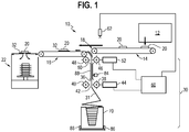
- a food production line 10 is shown schematically in connection with a substrate insertion system 30 that inserts a substrate 32 under a product 20 that is being carried on a conveyor 14, 16 of the food production line 10.
- the substrate insertion system 30 is preferably used in connection with a food production line 10. However, it can be used in other applications where a substrate 32 must be placed under a product 20 that is being carried along a conveyor 14, 16.
- the substrate insertion system 30 inserts a substrate 32 through a gap 18 formed in the product conveyor between an upstream conveyor 14 and a downstream conveyor 16. This is done in time with the product 20 traveling over the gap 18.
- the product 20 now placed on a substrate 32 is carried to a stacker 22 where the product and substrate are stacked for further packaging or processing.
- the substrate insertion system 30 includes a support frame 34 shown at least in part in FIGS. 2-6 . This can be part of an existing conveyor system or can be a separate frame.
- a substrate path 36 for the substrate 32 that is to be fed is defined between rollers and guides, as described in further detail below.
- a set of pull rollers 38, 40 is mounted to the frame 34 along the substrate path 36. These pull rollers 38, 40 define a pull roller nip 42 through which the substrate 32 is fed.
- a set of tear rollers 46, 48 are mounted to the frame 34 further along the substrate path 36.
- the tear rollers 46, 48 define a tear roller nip 50 through which the substrate 32 exiting the pull roller nip 42 is fed.
- Wire guides for example as shown at 88 in FIG. 1 , can be provided along the substrate path 36 in order to help guide the substrate as it is supplied.
- a pull roller drive 44 and a tear roller drive 52 are provided and associated with the set of pull rollers 38, 40 and the set of tear rollers, 46, 48, respectively. Typically on a single roller of a given set is driven. However, it would be possible to drive both rollers in each set.
- the pull roller drive 44 and the tear roller drive 52 are configured to be driven at the same or at different speeds. For example, the pull roller drive 44 can be switched off and on and the tear roller drive 52 can be run continuously in order to allow a substrate 32 that enters the tear roller nip 50 to be separated from the remainder of the substrate supply 31 as a single substrate sheet for placement beneath the product 20 through the gap 18 as shown in FIG. 1 .
- the pull roller drive 44 and the tear roller driver 52 can both be continuously driven at differing speeds to provide for higher speed placement of the substrates 32, with the pull roller drive 44 decelerating in a specifically timed manner in order to allow a sufficient difference in the speeds between the tear roller drive 52 and the pull roller drive 44 to cause a separation of the individual substrate 32 from the substrate supply 31 so that it can be fed through the gap 18 beneath the product 20 while not entirely stopping the feeding of the substrate supply 31.
- the pull roller drive 44 is a servo motor and the tear roller drive is also a separate servo motor.
- Servo motors allow for precise control of the rotation of the associated pull rollers 38, 40 or tear rollers 46, 48 so that the position of the substrate supply 31 as well as the separated individual substrates 32 can be accurately tracked without the need for separate tracking sensors along the substrate path 36.
- a controller GO controls the pull roller drive 44 and the tear roller drive 52 in order to control the timing of the insertion of individual substrates 32 separated from the substrate supply 31.
- the controller GO may be a PLC or may be microprocessor based, and may include a programmable memory.
- a sensor 62 is located along the product path defined by the conveyor 14, 16. This can be a break beam sensor that detects a position of the product 20 as it is carried along the upstream conveyor 14 which signals the controller GO that a substrate 32 needs to be inserted through the gap 18 beneath the product 20.
- the controller 60 actuates the pull roller drive 44 and the tear roller drive 52 in order to advance the substrate supply 31 a sufficient amount and then, preferably stops the pull roller drive 44 so that the tear roller drive 52 continues to advance the substrate supply 31, separating a single substrate 32 from the substrate supply 31 and inserting it beneath the product 20 in time with the product 20 passing over the gap 18 between the upstream and downstream conveyors 14, 16.
- the insertion is shown in the sequence of FIGS. 2, 3 , and 4 with the product 20 traveling from the upstream conveyor 14 to the downstream conveyor 16 as the single substrate 32 is inserted beneath the product.
- a pre-perforated substrate supply 31 is provided in a substrate box 70.
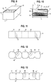
- the preferred embodiments of the pre-perforated substrate supply 31, 31', 32" are shown in detail in FIGS. 11-13 while a preferred substrate box 70 is shown in FIGS. 9 and 10 .
- the substrate box 70 preferably includes first and second opposing pairs of sidewalls 72, 73; 74, 75 and a top cover 76.
- a bottom is preferably also provided.
- the first opposing pairs of sidewalls 72, 73 define a first side-to-side guidance for the pre-perforated substrate supply 31. This is created by a spacing of the substrate supply 31 at .25 inches or less from each of the sidewalls 72, 73.
- the top cover 76 defines an opening 78, shown in detail in FIGS.
- a leaf 86 of the pre-perforated substrate supply 31 having a length L that is less than 50% of a length X of a leaf 86 of the pre-perforated substrate supply 31.
- These leafs 86 are arranged in a fan-folded manner in the substrate box 70 as shown in FIG. 10 and schematically represented in FIG. 1 .
- the length of a single leaf 86 can correspond to a length of a single substrate, or there can be multiple single substrates 32 (still connected together at the perforation lines) per leaf 86.
- each said substrate 32 of the pre-perforated substrate supply 31 is connected to at least one adjacent substrate 32 by a plurality of tabs 80 located between the substrates 32 formed by perforations.
- One or more of the individual substrates 32 defined between these perforation lines can form a leaf 86 as provided in the substrate box 70.
- the individual substrates can have trimmed corners 82, 82' that are formed at the same time as the perforations when the pre-perforated substrate 31', 31" is being manufactured. As shown, the trimmed corners 82 are angled and the trimmed corners 82' are rounded.
- the substrate box 70 is provided as a consumable along with the pre-perforated substrate supply 31, and the top cover 76 is formed by a top flap of the box 70.
- the opening 78 can be created by either cutting or removing a portion of the flap that is defined by markings on the substrate box 70.
- the opening 70 has a width W, shown in FIG. 9 , defined by a distance between an inside of the first opposing pair of sidewalls 72, 73.
- the length L of the opening is preferably less than 50% of the length X of a leaf 86, and is more preferably less than 40%, and can be less than 30%.
- the top cover 76 is adapted to apply friction to the pre-perforated substrate supply 31 that is drawn from the substrate box 70.
- a second side-to-side guidance 64 can be provided along the substrate path 36.
- This is shown as a turning bar 68 along the substrate path 36 around which the substrate supply 31 travels.
- Projections 66 in the form of rings, are located on the turning bar 68 in order to provide side-to-side tracking for the substrate supply 31 being fed along the substrate path 36.
- the pull roller drive 44 and the tear roller drive 52 are provided as servo motors and accordingly, tracking sensors for the position that is substrate supply 31 are not required. Instead, the position is tracked via the servo motors and the controller GO.
- the leading edge of the substrate supply 31 is required to be fed through the pull roller nip 42 and indexed at a leading edge locator 84, shown in FIG. 1 , so that the system can initiate with a known position of the leading edge of the substrate supply 31.
- This can be a visual marker or target that the operator can visually use to set the position of the leading edge of the pre-perforated substrate supply 31.
- positioning of the substrate box 70 is also controlled via guides 86 located on the frame 84 that are adapted to position of the substrate box 70 in a repeatable manner.
- a method for inserting substrates 32 under products being products carried on a conveyor 14, 16 is also provided.
- the method includes providing the substrate insertion system 30 including one or more features as discussed above.
- the pull rollers 38, 40 are driven with the pull roller drive 44 to advance the pre-perforated substrate supply 31 along the substrate path 36 to a predetermined position.
- the sensor 62 senses a product 20 traveling on the conveyor 14, 16 at a defined position and signals the controller 60 to advance the pre-perforated substrate supply 31 a predetermined distance via the pull rollers 38, 40 at a predetermined time such that the pre-perforated substrate supply 31 is engaged by the tear roller nip 50 between the tear rollers 46, 48.
- a single substrate 32 is separated from the pre-perforated substrate supply 31 by stopping the pull rollers 38, 40.
- separation can be achieved by decelerating the pull rollers 38, 40 to a slower speed than the tear rollers 46, 48.
- the tear rollers 46, 48 then advance the single substrate 32 separated from the pre-perforated substrate supply 31 by breaking the tabs 80 located between individual substrates on the pre-perforated substrate supply 31 and insert the single substrate 32 beneath the product 20 as it travels across the gap 18 along the product path on the conveyor 14, 16.
Landscapes
- Engineering & Computer Science (AREA)
- Life Sciences & Earth Sciences (AREA)
- Mechanical Engineering (AREA)
- Food Science & Technology (AREA)
- Wood Science & Technology (AREA)
- Zoology (AREA)
- Chemical & Material Sciences (AREA)
- Polymers & Plastics (AREA)
- Making Paper Articles (AREA)
- Confectionery (AREA)
- Containers And Plastic Fillers For Packaging (AREA)
Abstract
Description
- The present invention relates to substrate insertion devices used in connection with food preparations, specifically for inserting a substrate beneath food preparations as they travel along a conveyor path.
- Food setups, meat patties and other food items are placed on substrates so that the setup, patty or other item can be stacked one on top of another for packaging in trays without the risk of the food items becoming intermixed or stuck together. Food setups may include sliced meats and cheeses, such as those used in sandwiches so that a food preparer can simply remove a setup and place it in a sandwich. Meat patties are typically hamburger, turkey burger or other types of patties which are formed and then stacked one upon the other prior to being placed in a tray and wrapped.
- It has been known to use an interleaver or paper placer for placing a substrate between the food setup, meat patty, or other item. Several known interleavers use roll stock for the substrate which is required to be cut to length and then inserted using a number of rollers that define nips that carry the substrate to an insertion point in the conveyor line, usually formed as a gap between two conveyors. A detector senses the product to be interleaved on the conveyor line, and the roll stock is advanced, cut, and then inserted or interleaved under the product as it crosses the gap. Given the high speeds of some production lines, which can require up to 300 products per minute being interleaved, controls are required for tensioning and guiding the substrate coming off the roll, and ensuring the proper timing for the cutting and transport operation to the point where the substrate is inserted. These known interleavers can be expensive and may occupy a substantial space along a food preparation line.
- There is the need for a more cost effective substrate interleaver/inserter which can be used in connection with food production lines that is simple to use and install and which can be easily integrated into existing production lines.
- Briefly stated, a substrate insertion system for insertion of a substrate under a product being carried on a conveyor, in particular under a food product being carried on a food processing line conveyor, is provided. The insertion system includes a support frame, which can be separate or part of the conveyor line, and a substrate path for substrate that is to be fed. Pull rollers are mounted to the frame along the substrate path, with the pull rollers defining a pull roller nip through which the substrate is fed. Tear rollers are also mounted to the frame along the substrate path, with the tear rollers defining a tear roller nip through which the substrate is fed. The tear rollers are downstream along the substrate path from the pull rollers. At least one pull roller drive and at least one tear roller drive are provided, with the pull roller drive and the tear roller drive being configured to be driven at different speeds. A controller controls the at least one pull roller drive and the at least one tear roller drive. A product sensor is located along a product path defined by the conveyor. A pre-perforated substrate supply is provided in a substrate box, with the substrate box including first and second opposing pairs of sidewalls and a top cover. The first opposing pair of sidewalls define a first side-to-side guidance for the pre-perforated fan-fold substrate, and the top cover defines an opening having a length that is less than 50% of a length of a leaf of the pre-perforated substrate supply, with the leafs being arranged in a fan-folded manner in the substrate box.
- In use, the pre-perforated substrate supply is fed through the pull roller nip, and indexed to a starting point provided by a leading edge locator located along the substrate path downstream from the pull roller nip. The product sensor detects a product traveling on a product conveyor and signals the controller. The controller activates the pull roller drive and the tear roller drive based on a timing for the product to arrive at a substrate insertion point located at a gap in the product conveyor line. The substrate supply advances along the substrate path in accordance with the required timing, the pull roller drive is stopped such that the tear rollers which continue to drive, separate a single substrate sheet from the substrate supply by rupturing the perforated connection of the lead sheet, which is pulled forward through the tear roller nip and inserted through the gap and beneath the product as it travels across the gap. This process continues for each sensed product. The substrate box acts to apply tension on the substrate supply, eliminating the need for dancer bars or other substrate supply feed sensors or drives. Sensors used for determining the position of the substrate along the substrate feed path can also be eliminated by using servo motors for the pull roller and tear roller drives since these allow for precise tracking of the substrate position once the leading edge of the substrate supply is indexed to the starting point. Accordingly a simple control system can be used that only relies on the product sensor and the speed of the product conveyor in order to insert single substrates.
- In another aspect, each substrate of the pre-perforated substrate supply is preferably connected to at least one adjacent substrate by a plurality of tabs located between trimmed corners prior to being inserted. Here, since the substrate supply is pre-perforated and provided in fan form in the substrate box, it is also possible to provide trimmed corners on each substrate. This is advantageous in food packaging applications since the corners of square or rectangular substrates sometimes extend into the sealing area for the stacked products requiring re-work or unusable packaged product, for example for stacked meat patties separated by substrates, if a substrate corner extends into the seal area for the wrapping material for the stacked product, it has to be manually removed from the processing line and re-packaged, or the product is discarded as unusable. The trimmed corners can be angled or rounded.
- Preferably, the top cover of the substrate box is formed by a top flap of the box. The top cover is adapted to apply friction to the pre-perforated substrate supply that is drawn from the substrate box. The opening in the substrate box has a width defined by a distance between an inside of the first opposing pair of sidewalls, and thus corresponds to and acts as part of the first side-to-side guidance.
- A second side-to-side guidance for the pre-perforated fan-fold substrate formed by projections on a turning bar along the substrate path around which the substrate supply travels.
- Preferably, positioning guides are provided that are located on the frame that are adapted to position the substrate box.
- A method of inserting substrates under products being carried on a conveyor is also provided, and includes providing a substrate insertion system for insertion of a substrate under a product being carried on a conveyor having one or more features of the invention described herein, driving the pull rollers with the pull roller drive to advance the pre-perforated substrate supply along the substrate path to a predetermined position, sensing a product traveling on the conveyor with the product sensor at a defined position and signaling the controller to advance the pre-perforated substrate supply a predetermined distance via the pull rollers at a predetermined time such that the pre-perforated substrate supply is engaged by the tear roller nip between the tear rollers, separating a single substrate from the pre-perforated substrate supply by stopping the pull rollers, and the tear rollers advancing the single substrate separated from the pre-perforated substrate supply along the substrate path and inserting the single substrate beneath the product as it travels across a gap along a product path on the conveyor.
- When used in connection with a food product line, such as meat patties, the food product with its associated substrate after substrate insertion, is stacked in the stacker and placed in trays for further packaging and/or processing.
- The foregoing summary as well as the following detailed description which will be best understood when reviewed in conjunction with the drawings, which illustrate a presenting preferred embodiment of the invention.
-
FIG. 1 is a schematic view of a food production line including a substrate insertion system. -
FIG. 2 is a top view showing a product traveling along a conveyor of the food production line. -
FIG. 3 is a top view similar toFIG. 2 showing the product traveling over a gap in the conveyor path and a substrate being inserted through the gap and beneath the product. -
FIG. 4 is a view similar toFIGS. 2 and 3 showing the product on the substrate continuing to travel along the conveyor for further processing. -
FIG. 5 is a view showing the substrate insertion system taken beneath the product conveyor. -
FIG. 6 is an additional view of the substrate insertion system taken beneath the conveyor showing a side-to-side guidance for the substrate supply. -
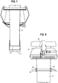
FIG. 7 is a view of the substrate insertion system showing the substrate leaving the substrate box. -
FIG. 8 is an additional view of the substrate insertion system taken below the conveyor showing the substrate supply traveling toward the pull rollers. -
FIG. 9 is a detailed view of an embodiment of the substrate box. -
FIG. 10 is a cross-sectional view taken through the substrate box ofFIG. 9 showing the fan-folded substrate leafs arranged in the substrate box with the substrate supply exiting through a cover opening in the substrate box. -
FIG. 11 is a plan view showing a portion of a first embodiment of a pre-perforated substrate supply. -
FIG. 12 is a plan view showing a second embodiment of a pre-perforated substrate supply. -
FIG. 13 is a plan view showing a third embodiment of a pre-perforated substrate supply. - Certain terminology is used in the following description for convenience only and is not considered limiting. Words such as "up", "down", "left", and "right" are used for convenience only in describing the directions of certain features noted in the drawings, and are not considered limiting. Additionally, the words "a" and "one" are defined as including one or more of the referenced items unless specifically noted.
- Referring to
FIG. 1 , afood production line 10 is shown schematically in connection with asubstrate insertion system 30 that inserts asubstrate 32 under aproduct 20 that is being carried on aconveyor food production line 10. Thesubstrate insertion system 30 is preferably used in connection with afood production line 10. However, it can be used in other applications where asubstrate 32 must be placed under aproduct 20 that is being carried along aconveyor - As schematically shown in
FIG. 1 , thesubstrate insertion system 30 inserts asubstrate 32 through agap 18 formed in the product conveyor between anupstream conveyor 14 and adownstream conveyor 16. This is done in time with theproduct 20 traveling over thegap 18. In thefood production line 10 shown, theproduct 20 now placed on asubstrate 32 is carried to astacker 22 where the product and substrate are stacked for further packaging or processing. - The
substrate insertion system 30 includes asupport frame 34 shown at least in part inFIGS. 2-6 . This can be part of an existing conveyor system or can be a separate frame. Asubstrate path 36 for thesubstrate 32 that is to be fed is defined between rollers and guides, as described in further detail below. Specifically, a set ofpull rollers frame 34 along thesubstrate path 36. These pullrollers substrate 32 is fed. A set oftear rollers frame 34 further along thesubstrate path 36. Thetear rollers substrate 32 exiting the pull roller nip 42 is fed. Wire guides, for example as shown at 88 inFIG. 1 , can be provided along thesubstrate path 36 in order to help guide the substrate as it is supplied. - A pull roller drive 44 and a
tear roller drive 52 are provided and associated with the set ofpull rollers tear roller drive 52 are configured to be driven at the same or at different speeds. For example, the pull roller drive 44 can be switched off and on and the tear roller drive 52 can be run continuously in order to allow asubstrate 32 that enters the tear roller nip 50 to be separated from the remainder of thesubstrate supply 31 as a single substrate sheet for placement beneath theproduct 20 through thegap 18 as shown inFIG. 1 . This is done in a timed manner with theproduct 20 being carried along theconveyor product 20 on theindividual substrate 32. Alternatively, the pull roller drive 44 and thetear roller driver 52 can both be continuously driven at differing speeds to provide for higher speed placement of thesubstrates 32, with the pull roller drive 44 decelerating in a specifically timed manner in order to allow a sufficient difference in the speeds between thetear roller drive 52 and the pull roller drive 44 to cause a separation of theindividual substrate 32 from thesubstrate supply 31 so that it can be fed through thegap 18 beneath theproduct 20 while not entirely stopping the feeding of thesubstrate supply 31. - Preferably, the pull roller drive 44 is a servo motor and the tear roller drive is also a separate servo motor. Servo motors allow for precise control of the rotation of the associated
pull rollers rollers substrate supply 31 as well as the separatedindividual substrates 32 can be accurately tracked without the need for separate tracking sensors along thesubstrate path 36. - Referring again to
FIG. 1 , a controller GO controls the pull roller drive 44 and thetear roller drive 52 in order to control the timing of the insertion ofindividual substrates 32 separated from thesubstrate supply 31. The controller GO may be a PLC or may be microprocessor based, and may include a programmable memory. - A
sensor 62 is located along the product path defined by theconveyor product 20 as it is carried along theupstream conveyor 14 which signals the controller GO that asubstrate 32 needs to be inserted through thegap 18 beneath theproduct 20. Thecontroller 60 actuates the pull roller drive 44 and thetear roller drive 52 in order to advance the substrate supply 31 a sufficient amount and then, preferably stops the pull roller drive 44 so that thetear roller drive 52 continues to advance thesubstrate supply 31, separating asingle substrate 32 from thesubstrate supply 31 and inserting it beneath theproduct 20 in time with theproduct 20 passing over thegap 18 between the upstream anddownstream conveyors FIGS. 2, 3 , and4 with theproduct 20 traveling from theupstream conveyor 14 to thedownstream conveyor 16 as thesingle substrate 32 is inserted beneath the product. - A
pre-perforated substrate supply 31 is provided in asubstrate box 70. The preferred embodiments of thepre-perforated substrate supply FIGS. 11-13 while apreferred substrate box 70 is shown inFIGS. 9 and 10 . Thesubstrate box 70 preferably includes first and second opposing pairs ofsidewalls top cover 76. A bottom is preferably also provided. The first opposing pairs ofsidewalls pre-perforated substrate supply 31. This is created by a spacing of thesubstrate supply 31 at .25 inches or less from each of thesidewalls top cover 76 defines anopening 78, shown in detail inFIGS. 9 and 10 , having a length L that is less than 50% of a length X of aleaf 86 of thepre-perforated substrate supply 31. Theseleafs 86 are arranged in a fan-folded manner in thesubstrate box 70 as shown inFIG. 10 and schematically represented inFIG. 1 . The length of asingle leaf 86 can correspond to a length of a single substrate, or there can be multiple single substrates 32 (still connected together at the perforation lines) perleaf 86. - As shown in
FIGS. 11-13 , each saidsubstrate 32 of thepre-perforated substrate supply 31 is connected to at least oneadjacent substrate 32 by a plurality oftabs 80 located between thesubstrates 32 formed by perforations. One or more of theindividual substrates 32 defined between these perforation lines can form aleaf 86 as provided in thesubstrate box 70. - As shown in
FIGS. 12 and 13 in connection with thesubstrate supply embodiments 31' and 31", the individual substrates can have trimmedcorners 82, 82' that are formed at the same time as the perforations when thepre-perforated substrate 31', 31" is being manufactured. As shown, the trimmedcorners 82 are angled and the trimmed corners 82' are rounded. These provide several advantages in connection with further processing and packaging of food products that are stacked on thesubstrates 32 in that there are no corners which can interfere with further wrapping and sealing of stacked product. - In the preferred embodiment, the
substrate box 70 is provided as a consumable along with thepre-perforated substrate supply 31, and thetop cover 76 is formed by a top flap of thebox 70. Theopening 78 can be created by either cutting or removing a portion of the flap that is defined by markings on thesubstrate box 70. Preferably, theopening 70 has a width W, shown inFIG. 9 , defined by a distance between an inside of the first opposing pair ofsidewalls leaf 86, and is more preferably less than 40%, and can be less than 30%. Thetop cover 76 is adapted to apply friction to thepre-perforated substrate supply 31 that is drawn from thesubstrate box 70. - Depending upon the particular application, as shown in
FIGS. 6 and8 , a second side-to-side guidance 64 can be provided along thesubstrate path 36. This is shown as a turningbar 68 along thesubstrate path 36 around which thesubstrate supply 31 travels.Projections 66, in the form of rings, are located on the turningbar 68 in order to provide side-to-side tracking for thesubstrate supply 31 being fed along thesubstrate path 36. - In the
substrate insertion system 30, preferably the pull roller drive 44 and thetear roller drive 52 are provided as servo motors and accordingly, tracking sensors for the position that issubstrate supply 31 are not required. Instead, the position is tracked via the servo motors and the controller GO. However, when thesubstrate supply 31 is first installed, the leading edge of thesubstrate supply 31 is required to be fed through the pull roller nip 42 and indexed at aleading edge locator 84, shown inFIG. 1 , so that the system can initiate with a known position of the leading edge of thesubstrate supply 31. This can be a visual marker or target that the operator can visually use to set the position of the leading edge of thepre-perforated substrate supply 31. - Additionally, as shown in
FIG. 1 , positioning of thesubstrate box 70 is also controlled viaguides 86 located on theframe 84 that are adapted to position of thesubstrate box 70 in a repeatable manner. - A method for inserting
substrates 32 under products being products carried on aconveyor substrate insertion system 30 including one or more features as discussed above. Thepull rollers pre-perforated substrate supply 31 along thesubstrate path 36 to a predetermined position. Thesensor 62 senses aproduct 20 traveling on theconveyor controller 60 to advance the pre-perforated substrate supply 31 a predetermined distance via thepull rollers pre-perforated substrate supply 31 is engaged by the tear roller nip 50 between thetear rollers single substrate 32 is separated from thepre-perforated substrate supply 31 by stopping thepull rollers pull rollers tear rollers tear rollers single substrate 32 separated from thepre-perforated substrate supply 31 by breaking thetabs 80 located between individual substrates on thepre-perforated substrate supply 31 and insert thesingle substrate 32 beneath theproduct 20 as it travels across thegap 18 along the product path on theconveyor - Having thus described in detail a preferred selection of embodiments of the present invention, it is to be appreciated and will be apparent to those skilled in the art that many physical changes could be made in the substrate insertion system without altering the inventive concepts and principles embodied therein. The present embodiments are therefore to be considered in all respects as illustrative and not restrictive, the scope of the invention being indicated by the appended claims rather than by the foregoing description, and all changes which come within the meaning and range of equivalency of the claims are therefore to be embraced therein.
Claims (13)
- A substrate insertion system for insertion of a substrate under a product being carried on a conveyor, comprising:
a support frame; a substrate path for substrate that is to be fed; pull rollers mounted to the support frame along the substrate path, the pull rollers defining a pull roller nip through which the substrate is fed; tear rollers mounted to the support frame along the substrate path, the tear rollers defining a tear roller nip through which the substrate is fed; a pull roller drive and a tear roller drive, the pull roller drive and the tear roller drive being configured to be driven at different speeds; a controller that controls the pull roller drive and the tear roller drive; a product sensor located along a product path defined by the conveyor; a pre-perforated substrate supply provided in a substrate box, the substrate box including first and second opposing pairs of sidewalls and a top cover, the first opposing pair of sidewalls defining a first side-to-side guidance for the pre-perforated substrate supply, and the top cover defining an opening having a length that is less than 50% of a length of a leaf of the pre-perforated substrate supply, said leafs being arranged in a fan-folded manner in the substrate box. - The substrate insertion system of claim 1, wherein each said substrate of the pre-perforated substrate supply is connected to at least one adjacent substrate by a plurality of tabs located between trimmed corners prior to being inserted.
- The substrate insertion system of claim 2, wherein the trimmed corners are angled.
- The substrate insertion system of claim 2, wherein the trimmed corners are rounded.
- The substrate insertion system of any preceding claim, wherein the top cover is formed by a top flap of the box.
- The substrate insertion system of any preceding claim, wherein the opening has a width defined by a distance between an inside of the first opposing pair of sidewalls.
- The substrate insertion system of any preceding claim, further comprising a second side-to-side guidance for the pre-perforated substrate formed by projections on a turning bar along the substrate path around which the substrate supply travels.
- The substrate insertion system of any preceding claim, wherein the pull roller drive comprises a servo motor.
- The substrate insertion system of any preceding claim, wherein the tear roller drive comprises a servo motor.
- The substrate insertion system of any preceding claim, further comprising a leading edge locator located along the substrate path downstream of the pull roller nip for setting an initial substrate position at a leading edge of the pre-perforated substrate supply.
- The substrate insertion system of any preceding claim, wherein the top cover is adapted to apply friction to the pre-perforated substrate supply that is drawn from the substrate box.
- The substrate insertion system of any preceding claim, further comprising positioning guides located on the support frame that are adapted to position the substrate box.
- A method of inserting substrates under products being carried on a conveyor, the method comprising:providing a substrate insertion system for insertion of a substrate under a product being carried on a conveyor, said substrate insertion system including a support frame, a substrate path for substrate that is to be fed, pull rollers mounted to the support frame along the substrate path, the pull rollers defining a pull roller nip through which the substrate is fed, tear rollers mounted to the support frame along the substrate path, the tear rollers defining a tear roller nip through which the substrate is fed, at least one pull roller drive and at least one tear roller drive,
with the at least one pull roller drive and the at least one tear roller drive being configured to be driven at different speeds, a controller that controls the at least one pull roller drive and the at least one tear roller drive, a product sensor located along a product path defined by the conveyor, and a pre-perforated substrate supply provided in a substrate box, the substrate box including first and second opposing pairs of sidewalls and a top cover, the first opposing pair of sidewalls defining a first side-to side guidance for the pre-perforated fan-fold substrate, and the top cover defining an opening having a length that is less than 50% of a length of a leaf of the pre-perforated substrate supply, said leafs being arranged in a fan-folded manner in the substrate box;driving the pull rollers with the at least one pull roller drive to advance the pre-perforated substrate supply along the substrate path to a predetermined position;sensing a product traveling on the conveyor with the product sensor at a defined position and signaling the controller to advance the pre-perforated substrate supply a predetermined distance via the pull rollers at a predetermined time such that the pre-perforated substrate supply is engaged by the tear roller nip between the tear rollers;separating a single substrate from the pre-perforated substrate supply by stopping the pull rollers; andthe tear rollers advancing the single substrate separated from the pre-perforated substrate supply along the substrate path and inserting the single substrate beneath the product as it travels across a gap along a product path on the conveyor.
Applications Claiming Priority (1)
| Application Number | Priority Date | Filing Date | Title |
|---|---|---|---|
| US201962842799P | 2019-05-03 | 2019-05-03 |
Publications (2)
| Publication Number | Publication Date |
|---|---|
| EP3732996A1 true EP3732996A1 (en) | 2020-11-04 |
| EP3732996B1 EP3732996B1 (en) | 2023-12-27 |
Family
ID=70482486
Family Applications (1)
| Application Number | Title | Priority Date | Filing Date |
|---|---|---|---|
| EP20172584.3A Active EP3732996B1 (en) | 2019-05-03 | 2020-05-01 | Pre-perforated substrate separator and insertion device for food preparation line pre-perforated substrate |
Country Status (5)
| Country | Link |
|---|---|
| US (1) | US11377245B2 (en) |
| EP (1) | EP3732996B1 (en) |
| CA (1) | CA3083695C (en) |
| ES (1) | ES2973754T3 (en) |
| MX (1) | MX2020004595A (en) |
Families Citing this family (2)
| Publication number | Priority date | Publication date | Assignee | Title |
|---|---|---|---|---|
| EP4556183A3 (en) * | 2020-06-26 | 2025-08-13 | Albert Handtmann Maschinenfabrik GmbH & Co. KG | Separating device |
| CN118220616B (en) * | 2024-05-23 | 2024-08-27 | 山东新华医疗器械股份有限公司 | Packaging equipment |
Citations (5)
| Publication number | Priority date | Publication date | Assignee | Title |
|---|---|---|---|---|
| GB672742A (en) * | 1949-10-22 | 1952-05-28 | Brecknell Munro And Rogers Ltd | Improvements in machines for moulding and wrapping plastic material, for example-butter |
| US4236855A (en) * | 1978-09-08 | 1980-12-02 | Warrick Equipment Corp. | Apparatus for and method of sequentially transporting, accumulating and stacking a predetermined number of groups of individual similar flat articles and thereafter depositing the entire stack on a conveyor |
| EP0376754A2 (en) * | 1988-12-29 | 1990-07-04 | Toppan Moore Company, Ltd. | Continuous paper sheet tearing-up apparatus |
| US5768857A (en) * | 1996-05-02 | 1998-06-23 | Lawrence A. Ward | Multiple perforating, automatic food preparation line having in-line foldover for food set-ups |
| WO2009149322A1 (en) * | 2008-06-05 | 2009-12-10 | Packaging Progressions, Inc. | Reduced footprint substrate interleaver for food preparation line |
Family Cites Families (2)
| Publication number | Priority date | Publication date | Assignee | Title |
|---|---|---|---|---|
| GB2400601B (en) * | 2002-02-21 | 2005-11-09 | Gen Binding Corp | Low cost in-line punching system |
| US20190210383A1 (en) * | 2016-09-08 | 2019-07-11 | Hewlett-Packard Development Company, L.P. | Print media pick and feed |
-
2020
- 2020-04-23 CA CA3083695A patent/CA3083695C/en active Active
- 2020-04-27 US US16/859,276 patent/US11377245B2/en active Active
- 2020-05-01 ES ES20172584T patent/ES2973754T3/en active Active
- 2020-05-01 EP EP20172584.3A patent/EP3732996B1/en active Active
- 2020-07-13 MX MX2020004595A patent/MX2020004595A/en unknown
Patent Citations (5)
| Publication number | Priority date | Publication date | Assignee | Title |
|---|---|---|---|---|
| GB672742A (en) * | 1949-10-22 | 1952-05-28 | Brecknell Munro And Rogers Ltd | Improvements in machines for moulding and wrapping plastic material, for example-butter |
| US4236855A (en) * | 1978-09-08 | 1980-12-02 | Warrick Equipment Corp. | Apparatus for and method of sequentially transporting, accumulating and stacking a predetermined number of groups of individual similar flat articles and thereafter depositing the entire stack on a conveyor |
| EP0376754A2 (en) * | 1988-12-29 | 1990-07-04 | Toppan Moore Company, Ltd. | Continuous paper sheet tearing-up apparatus |
| US5768857A (en) * | 1996-05-02 | 1998-06-23 | Lawrence A. Ward | Multiple perforating, automatic food preparation line having in-line foldover for food set-ups |
| WO2009149322A1 (en) * | 2008-06-05 | 2009-12-10 | Packaging Progressions, Inc. | Reduced footprint substrate interleaver for food preparation line |
Also Published As
| Publication number | Publication date |
|---|---|
| MX2020004595A (en) | 2020-11-04 |
| EP3732996B1 (en) | 2023-12-27 |
| CA3083695C (en) | 2026-03-03 |
| US11377245B2 (en) | 2022-07-05 |
| US20200346805A1 (en) | 2020-11-05 |
| CA3083695A1 (en) | 2020-11-03 |
| ES2973754T3 (en) | 2024-06-24 |
Similar Documents
| Publication | Publication Date | Title |
|---|---|---|
| US7712287B2 (en) | Coupon insertion apparatus and method | |
| EP2081831B1 (en) | Perforated film wrapping machine | |
| US5138821A (en) | High speed inserter fed from roll material | |
| US6217497B1 (en) | Stand-up apparatus for producing flexible pouches | |
| EP3732996B1 (en) | Pre-perforated substrate separator and insertion device for food preparation line pre-perforated substrate | |
| EP0615490B1 (en) | Continuous form and apparatus for forming letter sheets therefrom | |
| EP3395702A1 (en) | Sealing device | |
| EP0443787B1 (en) | Article wrapping apparatus | |
| DK168153B1 (en) | Apparatus and method for automatically forming and stacking disc products | |
| US20120289389A1 (en) | Apparatus for forming a plurality of flexible pouches from a continuous web of film | |
| EP1591364B1 (en) | Process for feeding products of variable height and length into a continuous packaging apparatus and packaging apparatus | |
| EP3265386B1 (en) | Device for continuous compensation of stretching of film during drawing applicable on packaging machines | |
| US12129059B2 (en) | Apparatus for the track individual provision of sheet material for placing underneath | |
| US5740709A (en) | Two stage continuous web cutting system and method | |
| EP3119682A1 (en) | Labelling machine and method | |
| JP2005314001A5 (en) | ||
| EP0084299A1 (en) | System for regulating the feed of articles to a wrapping machine | |
| EP1449770B1 (en) | Machine for producing strip packages | |
| EP3261936B1 (en) | Wrapping group and wrapping method for wrapping products, in particular editorial products, in containment bands | |
| US20050067750A1 (en) | Paper jam detector for automatic food processing line | |
| EP0237299B1 (en) | Feed apparatus | |
| EP3501838B1 (en) | Saddle-stitch book binding system | |
| GB2154923A (en) | Severing sheets from a web | |
| EP3093245A1 (en) | Cutting wrapping film on a lap seal machine | |
| GB2204717A (en) | Packaging machine control |
Legal Events
| Date | Code | Title | Description |
|---|---|---|---|
| PUAI | Public reference made under article 153(3) epc to a published international application that has entered the european phase |
Free format text: ORIGINAL CODE: 0009012 |
|
| STAA | Information on the status of an ep patent application or granted ep patent |
Free format text: STATUS: THE APPLICATION HAS BEEN PUBLISHED |
|
| STAA | Information on the status of an ep patent application or granted ep patent |
Free format text: STATUS: REQUEST FOR EXAMINATION WAS MADE |
|
| AK | Designated contracting states |
Kind code of ref document: A1 Designated state(s): AL AT BE BG CH CY CZ DE DK EE ES FI FR GB GR HR HU IE IS IT LI LT LU LV MC MK MT NL NO PL PT RO RS SE SI SK SM TR |
|
| AX | Request for extension of the european patent |
Extension state: BA ME |
|
| 17P | Request for examination filed |
Effective date: 20201021 |
|
| RBV | Designated contracting states (corrected) |
Designated state(s): AL AT BE BG CH CY CZ DE DK EE ES FI FR GB GR HR HU IE IS IT LI LT LU LV MC MK MT NL NO PL PT RO RS SE SI SK SM TR |
|
| RAP3 | Party data changed (applicant data changed or rights of an application transferred) |
Owner name: PACPROINC, LLC |
|
| REG | Reference to a national code |
Ref country code: DE Ref legal event code: R079 Free format text: PREVIOUS MAIN CLASS: A23P0020200000 Ipc: A22C0017000000 Ref document number: 602020023267 Country of ref document: DE |
|
| GRAP | Despatch of communication of intention to grant a patent |
Free format text: ORIGINAL CODE: EPIDOSNIGR1 |
|
| STAA | Information on the status of an ep patent application or granted ep patent |
Free format text: STATUS: GRANT OF PATENT IS INTENDED |
|
| RIC1 | Information provided on ipc code assigned before grant |
Ipc: B65B 57/12 20060101ALI20230707BHEP Ipc: B65B 25/08 20060101ALI20230707BHEP Ipc: A22C 7/00 20060101ALI20230707BHEP Ipc: A23P 10/10 20160101ALI20230707BHEP Ipc: A23P 20/20 20160101ALI20230707BHEP Ipc: A22C 17/00 20060101AFI20230707BHEP |
|
| INTG | Intention to grant announced |
Effective date: 20230727 |
|
| GRAS | Grant fee paid |
Free format text: ORIGINAL CODE: EPIDOSNIGR3 |
|
| GRAA | (expected) grant |
Free format text: ORIGINAL CODE: 0009210 |
|
| STAA | Information on the status of an ep patent application or granted ep patent |
Free format text: STATUS: THE PATENT HAS BEEN GRANTED |
|
| AK | Designated contracting states |
Kind code of ref document: B1 Designated state(s): AL AT BE BG CH CY CZ DE DK EE ES FI FR GB GR HR HU IE IS IT LI LT LU LV MC MK MT NL NO PL PT RO RS SE SI SK SM TR |
|
| P01 | Opt-out of the competence of the unified patent court (upc) registered |
Effective date: 20231122 |
|
| REG | Reference to a national code |
Ref country code: GB Ref legal event code: FG4D |
|
| REG | Reference to a national code |
Ref country code: CH Ref legal event code: EP |
|
| REG | Reference to a national code |
Ref country code: DE Ref legal event code: R096 Ref document number: 602020023267 Country of ref document: DE |
|
| REG | Reference to a national code |
Ref country code: IE Ref legal event code: FG4D |
|
| REG | Reference to a national code |
Ref country code: NL Ref legal event code: FP |
|
| REG | Reference to a national code |
Ref country code: SE Ref legal event code: TRGR |
|
| PG25 | Lapsed in a contracting state [announced via postgrant information from national office to epo] |
Ref country code: GR Free format text: LAPSE BECAUSE OF FAILURE TO SUBMIT A TRANSLATION OF THE DESCRIPTION OR TO PAY THE FEE WITHIN THE PRESCRIBED TIME-LIMIT Effective date: 20240328 |
|
| REG | Reference to a national code |
Ref country code: LT Ref legal event code: MG9D |
|
| PG25 | Lapsed in a contracting state [announced via postgrant information from national office to epo] |
Ref country code: LT Free format text: LAPSE BECAUSE OF FAILURE TO SUBMIT A TRANSLATION OF THE DESCRIPTION OR TO PAY THE FEE WITHIN THE PRESCRIBED TIME-LIMIT Effective date: 20231227 |
|
| PG25 | Lapsed in a contracting state [announced via postgrant information from national office to epo] |
Ref country code: LT Free format text: LAPSE BECAUSE OF FAILURE TO SUBMIT A TRANSLATION OF THE DESCRIPTION OR TO PAY THE FEE WITHIN THE PRESCRIBED TIME-LIMIT Effective date: 20231227 Ref country code: GR Free format text: LAPSE BECAUSE OF FAILURE TO SUBMIT A TRANSLATION OF THE DESCRIPTION OR TO PAY THE FEE WITHIN THE PRESCRIBED TIME-LIMIT Effective date: 20240328 Ref country code: FI Free format text: LAPSE BECAUSE OF FAILURE TO SUBMIT A TRANSLATION OF THE DESCRIPTION OR TO PAY THE FEE WITHIN THE PRESCRIBED TIME-LIMIT Effective date: 20231227 Ref country code: BG Free format text: LAPSE BECAUSE OF FAILURE TO SUBMIT A TRANSLATION OF THE DESCRIPTION OR TO PAY THE FEE WITHIN THE PRESCRIBED TIME-LIMIT Effective date: 20240327 |
|
| REG | Reference to a national code |
Ref country code: AT Ref legal event code: MK05 Ref document number: 1643641 Country of ref document: AT Kind code of ref document: T Effective date: 20231227 |
|
| PG25 | Lapsed in a contracting state [announced via postgrant information from national office to epo] |
Ref country code: RS Free format text: LAPSE BECAUSE OF FAILURE TO SUBMIT A TRANSLATION OF THE DESCRIPTION OR TO PAY THE FEE WITHIN THE PRESCRIBED TIME-LIMIT Effective date: 20231227 Ref country code: NO Free format text: LAPSE BECAUSE OF FAILURE TO SUBMIT A TRANSLATION OF THE DESCRIPTION OR TO PAY THE FEE WITHIN THE PRESCRIBED TIME-LIMIT Effective date: 20240327 Ref country code: LV Free format text: LAPSE BECAUSE OF FAILURE TO SUBMIT A TRANSLATION OF THE DESCRIPTION OR TO PAY THE FEE WITHIN THE PRESCRIBED TIME-LIMIT Effective date: 20231227 Ref country code: HR Free format text: LAPSE BECAUSE OF FAILURE TO SUBMIT A TRANSLATION OF THE DESCRIPTION OR TO PAY THE FEE WITHIN THE PRESCRIBED TIME-LIMIT Effective date: 20231227 |
|
| REG | Reference to a national code |
Ref country code: ES Ref legal event code: FG2A Ref document number: 2973754 Country of ref document: ES Kind code of ref document: T3 Effective date: 20240624 |
|
| PG25 | Lapsed in a contracting state [announced via postgrant information from national office to epo] |
Ref country code: IS Free format text: LAPSE BECAUSE OF FAILURE TO SUBMIT A TRANSLATION OF THE DESCRIPTION OR TO PAY THE FEE WITHIN THE PRESCRIBED TIME-LIMIT Effective date: 20240427 |
|
| PG25 | Lapsed in a contracting state [announced via postgrant information from national office to epo] |
Ref country code: AT Free format text: LAPSE BECAUSE OF FAILURE TO SUBMIT A TRANSLATION OF THE DESCRIPTION OR TO PAY THE FEE WITHIN THE PRESCRIBED TIME-LIMIT Effective date: 20231227 Ref country code: CZ Free format text: LAPSE BECAUSE OF FAILURE TO SUBMIT A TRANSLATION OF THE DESCRIPTION OR TO PAY THE FEE WITHIN THE PRESCRIBED TIME-LIMIT Effective date: 20231227 |
|
| PG25 | Lapsed in a contracting state [announced via postgrant information from national office to epo] |
Ref country code: SK Free format text: LAPSE BECAUSE OF FAILURE TO SUBMIT A TRANSLATION OF THE DESCRIPTION OR TO PAY THE FEE WITHIN THE PRESCRIBED TIME-LIMIT Effective date: 20231227 |
|
| PG25 | Lapsed in a contracting state [announced via postgrant information from national office to epo] |
Ref country code: SM Free format text: LAPSE BECAUSE OF FAILURE TO SUBMIT A TRANSLATION OF THE DESCRIPTION OR TO PAY THE FEE WITHIN THE PRESCRIBED TIME-LIMIT Effective date: 20231227 Ref country code: SK Free format text: LAPSE BECAUSE OF FAILURE TO SUBMIT A TRANSLATION OF THE DESCRIPTION OR TO PAY THE FEE WITHIN THE PRESCRIBED TIME-LIMIT Effective date: 20231227 Ref country code: RO Free format text: LAPSE BECAUSE OF FAILURE TO SUBMIT A TRANSLATION OF THE DESCRIPTION OR TO PAY THE FEE WITHIN THE PRESCRIBED TIME-LIMIT Effective date: 20231227 Ref country code: IS Free format text: LAPSE BECAUSE OF FAILURE TO SUBMIT A TRANSLATION OF THE DESCRIPTION OR TO PAY THE FEE WITHIN THE PRESCRIBED TIME-LIMIT Effective date: 20240427 Ref country code: EE Free format text: LAPSE BECAUSE OF FAILURE TO SUBMIT A TRANSLATION OF THE DESCRIPTION OR TO PAY THE FEE WITHIN THE PRESCRIBED TIME-LIMIT Effective date: 20231227 Ref country code: CZ Free format text: LAPSE BECAUSE OF FAILURE TO SUBMIT A TRANSLATION OF THE DESCRIPTION OR TO PAY THE FEE WITHIN THE PRESCRIBED TIME-LIMIT Effective date: 20231227 Ref country code: AT Free format text: LAPSE BECAUSE OF FAILURE TO SUBMIT A TRANSLATION OF THE DESCRIPTION OR TO PAY THE FEE WITHIN THE PRESCRIBED TIME-LIMIT Effective date: 20231227 |
|
| PG25 | Lapsed in a contracting state [announced via postgrant information from national office to epo] |
Ref country code: PL Free format text: LAPSE BECAUSE OF FAILURE TO SUBMIT A TRANSLATION OF THE DESCRIPTION OR TO PAY THE FEE WITHIN THE PRESCRIBED TIME-LIMIT Effective date: 20231227 Ref country code: PT Free format text: LAPSE BECAUSE OF FAILURE TO SUBMIT A TRANSLATION OF THE DESCRIPTION OR TO PAY THE FEE WITHIN THE PRESCRIBED TIME-LIMIT Effective date: 20240429 |
|
| PG25 | Lapsed in a contracting state [announced via postgrant information from national office to epo] |
Ref country code: PT Free format text: LAPSE BECAUSE OF FAILURE TO SUBMIT A TRANSLATION OF THE DESCRIPTION OR TO PAY THE FEE WITHIN THE PRESCRIBED TIME-LIMIT Effective date: 20240429 Ref country code: PL Free format text: LAPSE BECAUSE OF FAILURE TO SUBMIT A TRANSLATION OF THE DESCRIPTION OR TO PAY THE FEE WITHIN THE PRESCRIBED TIME-LIMIT Effective date: 20231227 |
|
| REG | Reference to a national code |
Ref country code: DE Ref legal event code: R097 Ref document number: 602020023267 Country of ref document: DE |
|
| PG25 | Lapsed in a contracting state [announced via postgrant information from national office to epo] |
Ref country code: DK Free format text: LAPSE BECAUSE OF FAILURE TO SUBMIT A TRANSLATION OF THE DESCRIPTION OR TO PAY THE FEE WITHIN THE PRESCRIBED TIME-LIMIT Effective date: 20231227 |
|
| PG25 | Lapsed in a contracting state [announced via postgrant information from national office to epo] |
Ref country code: DK Free format text: LAPSE BECAUSE OF FAILURE TO SUBMIT A TRANSLATION OF THE DESCRIPTION OR TO PAY THE FEE WITHIN THE PRESCRIBED TIME-LIMIT Effective date: 20231227 |
|
| PLBE | No opposition filed within time limit |
Free format text: ORIGINAL CODE: 0009261 |
|
| STAA | Information on the status of an ep patent application or granted ep patent |
Free format text: STATUS: NO OPPOSITION FILED WITHIN TIME LIMIT |
|
| 26N | No opposition filed |
Effective date: 20240930 |
|
| REG | Reference to a national code |
Ref country code: CH Ref legal event code: PL |
|
| PG25 | Lapsed in a contracting state [announced via postgrant information from national office to epo] |
Ref country code: MC Free format text: LAPSE BECAUSE OF FAILURE TO SUBMIT A TRANSLATION OF THE DESCRIPTION OR TO PAY THE FEE WITHIN THE PRESCRIBED TIME-LIMIT Effective date: 20231227 |
|
| PG25 | Lapsed in a contracting state [announced via postgrant information from national office to epo] |
Ref country code: LU Free format text: LAPSE BECAUSE OF NON-PAYMENT OF DUE FEES Effective date: 20240501 |
|
| GBPC | Gb: european patent ceased through non-payment of renewal fee |
Effective date: 20240501 |
|
| PG25 | Lapsed in a contracting state [announced via postgrant information from national office to epo] |
Ref country code: MC Free format text: LAPSE BECAUSE OF FAILURE TO SUBMIT A TRANSLATION OF THE DESCRIPTION OR TO PAY THE FEE WITHIN THE PRESCRIBED TIME-LIMIT Effective date: 20231227 Ref country code: LU Free format text: LAPSE BECAUSE OF NON-PAYMENT OF DUE FEES Effective date: 20240501 Ref country code: CH Free format text: LAPSE BECAUSE OF NON-PAYMENT OF DUE FEES Effective date: 20240531 |
|
| REG | Reference to a national code |
Ref country code: BE Ref legal event code: MM Effective date: 20240531 |
|
| PG25 | Lapsed in a contracting state [announced via postgrant information from national office to epo] |
Ref country code: IE Free format text: LAPSE BECAUSE OF NON-PAYMENT OF DUE FEES Effective date: 20240501 |
|
| PG25 | Lapsed in a contracting state [announced via postgrant information from national office to epo] |
Ref country code: SI Free format text: LAPSE BECAUSE OF FAILURE TO SUBMIT A TRANSLATION OF THE DESCRIPTION OR TO PAY THE FEE WITHIN THE PRESCRIBED TIME-LIMIT Effective date: 20231227 Ref country code: BE Free format text: LAPSE BECAUSE OF NON-PAYMENT OF DUE FEES Effective date: 20240531 |
|
| PG25 | Lapsed in a contracting state [announced via postgrant information from national office to epo] |
Ref country code: FR Free format text: LAPSE BECAUSE OF NON-PAYMENT OF DUE FEES Effective date: 20240531 |
|
| PG25 | Lapsed in a contracting state [announced via postgrant information from national office to epo] |
Ref country code: GB Free format text: LAPSE BECAUSE OF NON-PAYMENT OF DUE FEES Effective date: 20240501 |
|
| PGFP | Annual fee paid to national office [announced via postgrant information from national office to epo] |
Ref country code: DE Payment date: 20250305 Year of fee payment: 6 |
|
| PGFP | Annual fee paid to national office [announced via postgrant information from national office to epo] |
Ref country code: ES Payment date: 20250603 Year of fee payment: 6 |
|
| PGFP | Annual fee paid to national office [announced via postgrant information from national office to epo] |
Ref country code: IT Payment date: 20250422 Year of fee payment: 6 |
|
| PG25 | Lapsed in a contracting state [announced via postgrant information from national office to epo] |
Ref country code: CY Free format text: LAPSE BECAUSE OF FAILURE TO SUBMIT A TRANSLATION OF THE DESCRIPTION OR TO PAY THE FEE WITHIN THE PRESCRIBED TIME-LIMIT; INVALID AB INITIO Effective date: 20200501 |
|
| PG25 | Lapsed in a contracting state [announced via postgrant information from national office to epo] |
Ref country code: HU Free format text: LAPSE BECAUSE OF FAILURE TO SUBMIT A TRANSLATION OF THE DESCRIPTION OR TO PAY THE FEE WITHIN THE PRESCRIBED TIME-LIMIT; INVALID AB INITIO Effective date: 20200501 |
|
| PGFP | Annual fee paid to national office [announced via postgrant information from national office to epo] |
Ref country code: SE Payment date: 20260312 Year of fee payment: 7 |
|
| PGFP | Annual fee paid to national office [announced via postgrant information from national office to epo] |
Ref country code: NL Payment date: 20260317 Year of fee payment: 7 |