EP3732446B1 - Scalable monolithic sensor assembly, controller, and methods of making and installing same - Google Patents
Scalable monolithic sensor assembly, controller, and methods of making and installing same Download PDFInfo
- Publication number
- EP3732446B1 EP3732446B1 EP18894480.5A EP18894480A EP3732446B1 EP 3732446 B1 EP3732446 B1 EP 3732446B1 EP 18894480 A EP18894480 A EP 18894480A EP 3732446 B1 EP3732446 B1 EP 3732446B1
- Authority
- EP
- European Patent Office
- Prior art keywords
- sensor assembly
- stem
- sensor head
- sensor
- flow pipe
- Prior art date
- Legal status (The legal status is an assumption and is not a legal conclusion. Google has not performed a legal analysis and makes no representation as to the accuracy of the status listed.)
- Active
Links
Images










Classifications
-
- G—PHYSICS
- G01—MEASURING; TESTING
- G01F—MEASURING VOLUME, VOLUME FLOW, MASS FLOW OR LIQUID LEVEL; METERING BY VOLUME
- G01F1/00—Measuring the volume flow or mass flow of fluid or fluent solid material wherein the fluid passes through a meter in a continuous flow
- G01F1/56—Measuring the volume flow or mass flow of fluid or fluent solid material wherein the fluid passes through a meter in a continuous flow by using electric or magnetic effects
- G01F1/58—Measuring the volume flow or mass flow of fluid or fluent solid material wherein the fluid passes through a meter in a continuous flow by using electric or magnetic effects by electromagnetic flowmeters
- G01F1/584—Measuring the volume flow or mass flow of fluid or fluent solid material wherein the fluid passes through a meter in a continuous flow by using electric or magnetic effects by electromagnetic flowmeters constructions of electrodes, accessories therefor
-
- G—PHYSICS
- G01—MEASURING; TESTING
- G01F—MEASURING VOLUME, VOLUME FLOW, MASS FLOW OR LIQUID LEVEL; METERING BY VOLUME
- G01F1/00—Measuring the volume flow or mass flow of fluid or fluent solid material wherein the fluid passes through a meter in a continuous flow
- G01F1/56—Measuring the volume flow or mass flow of fluid or fluent solid material wherein the fluid passes through a meter in a continuous flow by using electric or magnetic effects
- G01F1/58—Measuring the volume flow or mass flow of fluid or fluent solid material wherein the fluid passes through a meter in a continuous flow by using electric or magnetic effects by electromagnetic flowmeters
-
- G—PHYSICS
- G01—MEASURING; TESTING
- G01F—MEASURING VOLUME, VOLUME FLOW, MASS FLOW OR LIQUID LEVEL; METERING BY VOLUME
- G01F1/00—Measuring the volume flow or mass flow of fluid or fluent solid material wherein the fluid passes through a meter in a continuous flow
- G01F1/56—Measuring the volume flow or mass flow of fluid or fluent solid material wherein the fluid passes through a meter in a continuous flow by using electric or magnetic effects
- G01F1/58—Measuring the volume flow or mass flow of fluid or fluent solid material wherein the fluid passes through a meter in a continuous flow by using electric or magnetic effects by electromagnetic flowmeters
- G01F1/588—Measuring the volume flow or mass flow of fluid or fluent solid material wherein the fluid passes through a meter in a continuous flow by using electric or magnetic effects by electromagnetic flowmeters combined constructions of electrodes, coils or magnetic circuits, accessories therefor
-
- G—PHYSICS
- G01—MEASURING; TESTING
- G01F—MEASURING VOLUME, VOLUME FLOW, MASS FLOW OR LIQUID LEVEL; METERING BY VOLUME
- G01F15/00—Details of, or accessories for, apparatus of groups G01F1/00 - G01F13/00 insofar as such details or appliances are not adapted to particular types of such apparatus
-
- G—PHYSICS
- G01—MEASURING; TESTING
- G01F—MEASURING VOLUME, VOLUME FLOW, MASS FLOW OR LIQUID LEVEL; METERING BY VOLUME
- G01F15/00—Details of, or accessories for, apparatus of groups G01F1/00 - G01F13/00 insofar as such details or appliances are not adapted to particular types of such apparatus
- G01F15/18—Supports or connecting means for meters
- G01F15/185—Connecting means, e.g. bypass conduits
-
- G—PHYSICS
- G01—MEASURING; TESTING
- G01F—MEASURING VOLUME, VOLUME FLOW, MASS FLOW OR LIQUID LEVEL; METERING BY VOLUME
- G01F1/00—Measuring the volume flow or mass flow of fluid or fluent solid material wherein the fluid passes through a meter in a continuous flow
- G01F1/56—Measuring the volume flow or mass flow of fluid or fluent solid material wherein the fluid passes through a meter in a continuous flow by using electric or magnetic effects
- G01F1/58—Measuring the volume flow or mass flow of fluid or fluent solid material wherein the fluid passes through a meter in a continuous flow by using electric or magnetic effects by electromagnetic flowmeters
- G01F1/60—Circuits therefor
Definitions
- Typical uses in industry are generally for pipe diameters between 2.54 cm and 60.96 cm (one inch and 24 inches), although disclosed embodiments are equally applicable pipes up to 203.2 cm (80 inches) and larger.
- Many industrial and commercial systems utilize 15,24-30,48 cm (6-12 inch) piping which are equally compatible with sensor assembly 101.
- Example sensor assembly 101 is particularly advantageous for pipe sizes over 15,24 cm (6 inches) where prior sensors are more reliant on assumptions of the fluid flow within the pipe.
- FIGS. shows a section view of FIGS. 2 along section lines III-III. It is noted that although section lines III-III appears in the center, i.e., along axis 114, it is offset such that the FIG. 3 shows only certain components in section as will be evident from the remaining disclosure.
- the sensor head 100 is affixed to large diameter stem 132 at the stem cap 136. Large diameter stem transitions to a small diameter stem 134.
- the stem (including large diameter stem 132 and small diameter stem 134) may be formed as a single piece, or may be formed in several pieces and then joined together using known machining methods.
- the stem may be formed of, for example, stainless or other types of steel or steel alloys, for example 316 stainless steel. However, any material having sufficient strength for installation and under system operating conditions is suitable. Supporting the large diameter stem 132 and small diameter stem 134 is anchor 140, which will be discussed further below.
- Sensor head tube 102 may be made out of any easily machinable material which can withstand system temperatures and pressures including plastic and metal.
- sensor head tube includes acetal polymers.
- Head tube 102 may also be over molded over the coil 180 and electrodes 105, 106, 107, 108, 109, 110.
- AC alternating current
- the conductive fluid flows through the magnetic field in the direction of system flow 172 ( FIG. 1 ).
- the conductor (i.e., the conductive fluid) passing through the magnetic field induces an electric potential and current according to Faraday's law, which is indicative of the flow velocity. This voltage is measured between top electrodes 105, 106 and bottom electrodes 107, 108, respectively, to determine the flow rate of the liquid.
- connection features are formed directly on the large diameter stem 132, i.e., there is no separate stem cap 136.
- the end of large diameter stem 132 can be directly threaded or machined in order to provide the shaft threaded portion 202 and ledge 204.
- a head tube threaded portion 208 is formed which matches the thread of shaft threaded portion 202.
- a lip 210 is formed in between the head tube threaded portion 208 and the connecting end of sensor head tube 102.
- the lip 210 is sized such that sensor head tube 102 and lip 210 can deform sufficient enough to be pressed over ledge 204 when fastening the large diameter stem 132 and sensor head tube 102 together by hand and resulting in a snap-fit 200 ( FIG. 16 ).
- the snap-fit may be improved with o-ring 212.
- the junction includes both threads and snap-fit such that the threads, when the junction is being twisted assists in pressing the lip 210 over ledge 204. It should be noted that although embodiments are shown with a snap-fit feature, other embodiments may not include a snap-fit feature.
- the light plane 316 extends as a line about four to five feet away from valve 120, then a one degree rotation error will be even more apparent.
- the line will, in one example, be several feet long, e.g., 45.72 - 91.44 cm (18 - 36 inches), but will vary depending on the height of the sensor and the specific laser. The longer the line, the more accurate the alignment can be. Small discrepancies in angle will be multiplied by the length of the line to be easily identified and corrected for by turning the small diameter stem until the line is straight. Marking a straight line down the center of the pipe can further improve accuracy. The small diameter stem 134 would then be rotated until the laser line directly overlapped the marked line. This would further guarantee an accurate alignment.
- Integrator 412 provides negative feedback at 414 to AC couple the signal.
- the resulting analog signal is then pre-filtered through low pass filter (LPF) 416 for filtering to remove high frequency noise and to provide more gain.
- LPF low pass filter
- the signal is sent to BIAS 418 for final gain and appropriate bias to maximize the input resolution for digital processing at ADC 415.
- the gain and filter stage LPF 416 is designed so that its bandwidth is significantly lower than the bandwidth of the digital filter 417, ensuring that no aliasing of higher frequency signals would hamper the output of the digital filter 417. Further, the gain is adjusted to provide enough amplification to maximize the ADC's input range. In order to avoid "clipping" of the noise spikes, which creates harmonic distortion of the signal, the output of the filter is biased to the half-supply point, before being digitized.
Landscapes
- Physics & Mathematics (AREA)
- Fluid Mechanics (AREA)
- General Physics & Mathematics (AREA)
- Electromagnetism (AREA)
- Measuring Volume Flow (AREA)
- Measuring Fluid Pressure (AREA)
Description
- The disclosed embodiments generally relate to electromagnetic flow meters.
- Current insertion flow meters sample small areas of the flow through a pipe. Even those designed for large pipes simply sample several small sections. They then average these readings in an attempt to get an accurate flow measurement. All averages have some sort of weighting; the most common is to give each reading equal weights. Unfortunately, even if positioned such that each sensor has equal annular area, giving each sensor an equal rating does not lead to accurate measurements if the flow varies from that used to calibrate the meter. Giving unequal weightings can lead to accurate readings, but detailed information about the flow profile is required to give these weights. If the flow changes, the meter will be inaccurate. Separate cores require multiple pre-amps. This makes for a cumbersome and costly meter.
- Current insertion flow meters also utilize threaded joints in the body of the meter. Threaded joints are at risk for rotation and backing out after installation. Using a threaded joint as part of an electro-magnetic sensor head is challenging because the sensor must maintain alignment after installation and cannot be allowed to rotate. Snap fits prevent axial movement, but not rotation. They are not strong when bending.
- In addition, traditional insertion meters trade off two factors with stem design: insertion force and deflection strength. The smaller the stem, the less force is required to install the meter. A thin stem, however, is subject to unwanted deflection, vibration, fatigue, and breakage. Sensor assemblies according to the prior art are disclosed in
US 8136410 B2 andJP 2007 147631 A - Further, electrode wires in current insertion meters require shielding from their core's electromagnetic field. Typical cores accomplish this by running the electrode wires up the middle of the core where no field is generated. This can be expensive to machine, difficult to install, and adds complexity to the coil winding.
- Insertion flow meters are installed into a flow pipe using hot tap adapters that mount onto a ball valve. Traditional hot tap adapters anchor the meter at the top of the adapter event after installation. This is the furthest point from the force of the flow and the longest moment arm. This causes excessive deflection and vibration which negatively affect meter accuracy.
- Hand-insertable hot tappable insertion flow meters often have their alignment decoupled from their installation. That is, the meter can be threaded onto the valve fitting and then aligned afterwards. Mechanically assisted hot tappable flow meters, however, are typically locked into the orientation they are installed in. Threading the meter onto the valve fitting determines the angle of the meter to the flow. This means that the installer must often compromise between the correct installation torque of the fitting and the correct angle of the meter to the flow.
- Insertion flow meters' accuracy is also dependent on how consistently they are installed. Any difference in installation angle between where the meter was calibrated and where the meter was installed will worsen the accuracy of the meter.
- Current Insertion flow meter controllers must compensate for DC offset on electrodes which may be caused, for example, by electrochemical interaction of the electrodes. This decreases the accuracy of the meters. In addition, other insertion flow meters need to utilize precise timing and switching circuitry to read the signals increasing the overall complexity and cost of the meters.
-
-
FIG. 1 shows a perspective view of an example sensor assembly in accordance with disclosed embodiments; -
FIG. 2 shows the sensor assembly ofFIG. 1 when viewed in the direction of system flow in accordance with disclosed embodiments. -
FIGS. 3 shows a section view ofFIG. 2 along section lines III-III in accordance with disclosed embodiments. -
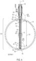
FIG. 4 shows a section view ofFIG. 3 along section line IV-IV in accordance with disclosed embodiments. -
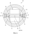
FIG. 5 shows a section view ofFIG. 4 along section lines V-V in accordance with disclosed embodiments. -
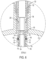
FIG 6 shows a detailed view ofdetail 6 ofFIG. 4 in accordance with disclosed embodiments. -
FIG. 7 shows a detailed view ofdetail 7 ofFIG. 4 in accordance with disclosed embodiments. -
FIG. 8 shows a perspective view of an example sensor head without an example sensor head tube in accordance with disclosed embodiments. -
FIGS. 9 shows a side view of an example sensor head without an example sensor head tube in accordance with disclosed embodiments. -
FIGS. 10 shows a front view of an example sensor head without an example sensor head tube in accordance with disclosed embodiments. -
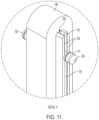
FIG. 11 shows a detail view ofdetail 11 ofFIG. 8 in accordance with disclosed embodiments. -
FIG. 12 shows a schematic view of an example sensor head and stem during assembly in accordance with disclosed embodiments. -
FIG. 13 is a section view along section line XII-XII ofFIG. 12 in accordance with disclosed embodiments. -
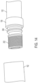
FIG. 14 is a schematic view of a sensor head tube and stem in accordance with disclosed embodiments. -
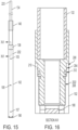
FIG. 15 shows a schematic view of an example sensor head and stem after connecting them together in accordance with disclosed embodiments. -
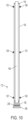
FIG. 16 is a section view along section line XVI-XVI ofFIG. 17 in accordance with disclosed embodiments. -
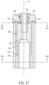
FIG. 17 is a schematic view of an example anchor prior to insertion of an example sensor head in accordance with disclosed embodiments. -
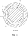
FIG. 18 is a section view along section line XVIII-XVIII ofFIG. 17 in accordance with disclosed embodiments. -
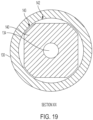
FIG. 19 is a section view along section line XIX-XIX ofFIG. 19 in accordance with disclosed embodiments. -
FIGS. 20 and 21 show an example sensor assembly in two stages of installation in accordance with disclosed embodiments. -
FIG. 22 shows a perspective view of an examplemechanical insertion device 260 in accordance with disclosed embodiments. -
FIG. 23 shows a front schematic view of an examplemechanical insertion device 260 in accordance with disclosed embodiments. -
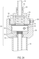
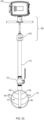
FIG. 24 shows a front schematic view of an example mechanical insertion device in accordance with disclosed embodiments. -
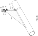
FIG. 25 shows a schematic perspective view of an example controller and line emitting light in accordance with disclosed embodiments. -
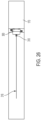
FIG. 26 shows a schematic top view of theFIG. 25 in accordance with disclosed embodiments. -
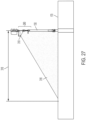
FIG. 27 shows a schematic front view of theFIG. 25 in accordance with disclosed embodiments. -
FIG. 28 shows a magnetic field density plot of example coils and an example core in accordance with disclosed embodiments. -
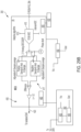
FIGS. 29A and29B show electrical schematic block diagrams of a controller and sensor head in accordance with disclosed embodiments. -
FIG. 30 shows a method in accordance with disclosed embodiments; and; -
FIG. 31 shows the sensor assembly ofFIG. 1 with the mechanical insertion device ofFIG. 24 when viewed in the direction of system flow in accordance with disclosed embodiments. -
FIG. 1 illustrates an overview perspective view of anexample sensor assembly 101 installed on and within aflow pipe 170. It should be noted that only a section offlow pipe 170 is shown in full. Other portions offlow pipe 170 are shown in dashed line for clarity. Theflow pipe 170 is a section of a system, typically a commercial or industrial system, in which the system flow 172 (either velocity or volumetric or mass flow rate) is desired by the system designer or customer to measured. Theflow pipe 170 may be any size diameter pipe. Thesensor assembly 101 would be scaled appropriately for the pipe size such that thesensor head 100 and associated components (discussed below) goes across the entire internal diameter of the pipe. Typical uses in industry are generally for pipe diameters between 2.54 cm and 60.96 cm (one inch and 24 inches), although disclosed embodiments are equally applicable pipes up to 203.2 cm (80 inches) and larger. Many industrial and commercial systems utilize 15,24-30,48 cm (6-12 inch) piping which are equally compatible withsensor assembly 101.Example sensor assembly 101 is particularly advantageous for pipe sizes over 15,24 cm (6 inches) where prior sensors are more reliant on assumptions of the fluid flow within the pipe. - Example systems include, but are not limited to, chillers, HVAC (heating, ventilation, and air conditioning), food processing, water treatment, water, water distribution, gas, agriculture, chemical refinement and manufacturing, and liquids, slurries, petrochemical, and pharmaceutical systems. For the remaining portion of this specification, we will refer to "fluid" as meaning any fluid or fluid-like material which is capable of inducing a current when flowing through a magnetic field.
Sensor assembly 101 may be used with other fluids and systems provided the fluid has enough conductivity to induce a current when flowing through a magnetic field. Most water based fluids include this property.System flow 172 withinflow pipe 170 is generally parallel with the pipe and perpendicular with the longitudinal access of the sensor assembly. The relative motion between thesystem flow 172 and thestationary sensor assembly 101, as described below, creates an electrical signal which is then converted into a flow velocity or volumetric or mass flow rate. - The sensor assembly includes a
sensor head 100, which generates a magnetic field and measures the electrical potential (voltage or "V") generated by the flow velocity at least one top electrode and at least one bottom electrode, which will be discussed below. The voltage is carried electrically to thecontroller 300 which is mounted outside offlow pipe 170. The internal construction and functionality of thesensor head 100 will be discussed in greater detail below. - Affixed to the
flow pipe 170, typically at installation of the system, isvalve 120.Valve 120 andflow pipe 170 may have ashort stub 171 of interceding pipe, which may be part offlow pipe 170 or affixed to it. However, such astub 171 would only affect the overall length required for the disclosedsensor assembly 101, which is easily scalable depending on the application. As such, the stub will not be discussed further.Valve 120, typically a ball valve, has a sufficient direct path through its center when open to allow thesensor head 100 to be inserted through thevalve 120 during installation of the sensor assembly. Thevalve 120 has anaxis 114 in the center of thevalve 120 and which is perpendicular to theflow pipe 170 andsystem flow 172. The accuracy of thesensor head 100 and the resulting flow velocity depends upon the degree to which the longitudinal axis of thesensor head 100 is perpendicular to thesystem flow 172. And, becausesensor head 100 is inserted throughvalve 120 during installation (discussed below), the longitudinal axis of thesensor head 100, when aligned, should coincide withaxis 114. As will be discussed below, the alignment features in theexample sensor assembly 101 have improvements over prior known sensors. - Prior to installation, the
sensor head 100 is retracted withinhot tap adapter 130. At installation,hot tap adapter 130 is connected tovalve 120. Thehot tap adapter 130 may be detachably connected through, for example, a threaded connection betweenvalve 120 andhot tap adapter 130, or in an alternative, fixedly connected via compression, welding, or the like. Thesensor head 100 is affixed to a stem, discussed further below, which extends throughhot tap adapter 130 tomechanical insertion device 260, which will also be discussed further below. After thehot tap adapter 130 is connected tovalve 120, thevalve 120 is opened and the sensor head is inserted intoflow pipe 170 until it bottoms out. Further details with respect to installation will be discussed below. -
FIG. 2 shows the sensor assembly ofFIG. 1 when viewed in the direction ofsystem flow 172. In the top, bottom, and middle regions of thesensor head 100, are holes in whichelectrodes flow pipe 170. As shown there is a lefttop electrode 105, a righttop electrode 106, aleft bottom electrode 107, a rightbottom electrode 108, aleft center electrode 109, andright center electrode 110. Thecenter electrodes sensor head 100, a voltage measurement is taken across lefttop electrode 105 and leftbottom electrode 107. To measure the right portion of the sensor head, a voltage measurement is taken across righttop electrode 106 and rightbottom electrode 108. In another configuration, both top electrodes 105,106 and bottom electrodes, 107,108 are electrically connected, respectively, such that a single measurement is taken. i.e., between top and bottom electrodes. - This arrangement of electrodes results in only two depths of measurement, at the top and bottom of the
sensor head 100, i.e., respectively proximate or next to the inner surface 173 of flow 170 (at opposing side of the flow pipe 170). It is noted that the top andbottom electrodes flow pipe 170. That is, the bottom andtop electrodes flow pipe 170. Measuring the potential between two depths of measurement across the diameter of theflow pipe 170 results in improved accuracy as compared to measuring multiple sections of the pipe and then averaging the measurements together as done in prior sensors. Extending the distance between the electrodes also increases the voltage potential and boosts meter performance. All of the fluid in the sensing area will be included in the voltage potential integration and will contribute to the meter's reading. The larger the area, the more fluid that is included and the more accurate the meter. Prior known sensors stretch less than 10% of large pipe diameters. Including a large sample area in theexample sensor head 100 allows high performance in areas of changing flow profile. While the areas of high and low velocity may shift, because they are all included into a single integration they will still contribute to the overall voltage no matter their location. Because there are only two depths of measurement, thesensor head 100 is easily scalable to any dimension pipe without having to re-adjust electrode spacing and eliminates wired connections between electrodes and signal conditioning circuitry as compared to other sensors which must average together several voltage measurements across the pipe diameter. - FIGS. shows a section view of
FIGS. 2 along section lines III-III. It is noted that although section lines III-III appears in the center, i.e., alongaxis 114, it is offset such that theFIG. 3 shows only certain components in section as will be evident from the remaining disclosure. Thesensor head 100 is affixed tolarge diameter stem 132 at thestem cap 136. Large diameter stem transitions to asmall diameter stem 134. The stem (includinglarge diameter stem 132 and small diameter stem 134) may be formed as a single piece, or may be formed in several pieces and then joined together using known machining methods. The stem may be formed of, for example, stainless or other types of steel or steel alloys, for example 316 stainless steel. However, any material having sufficient strength for installation and under system operating conditions is suitable. Supporting thelarge diameter stem 132 andsmall diameter stem 134 isanchor 140, which will be discussed further below. - The
small diameter stem 134 protrudes out of the top ofhot tap adapter 130 and throughtop seal cap 252.Top seal cap 252 seals the system pressure from escaping to atmosphere and seals againstsmall diameter stem 134 with o-ring orseal 254.Top seal cap 252 may be fastened with threads, compression, or welding, or other mechanical means sufficient to withstand system pressures tohot tap adapter 130. Small diameter stem 134 also protrudes throughcollar 150, spring or springs 152, andupper adjustment plate 154, each of which will be discussed further below. The bottom of the sensor head tube is sealed withbottom seal cap 192. -
FIG. 4 shows a section view ofFIG. 3 along section line IVI-IV. Thesensor head 100 includes one or more field coils 180, for example made of copper wire, wound around acore 104. Other conductive materials may also be used for the field coils 180 which are sufficient to conduct the field coil current. The field coils 180 are wound in-line with the system flow 172 (FIG. 1 ), that is, the area inside of the field coils is generally parallel with thesystem flow 172. As shown inFIG. 4 , the section of field coils 180 shows wires going into and coming out of the page at the top and bottom ofcore 104. The field coils 180 andcore 104 are withinsensor head tube 102, which serves to protect the internal components.Sensor head tube 102 may be made out of any easily machinable material which can withstand system temperatures and pressures including plastic and metal. In one example, sensor head tube includes acetal polymers.Head tube 102 may also be over molded over thecoil 180 andelectrodes field coil 180 is energized with alternating current (AC), an alternating magnetic field is generated (see, for exampleFIG. 28 showing magnetic field density). The conductive fluid flows through the magnetic field in the direction of system flow 172 (FIG. 1 ). The conductor (i.e., the conductive fluid) passing through the magnetic field induces an electric potential and current according to Faraday's law, which is indicative of the flow velocity. This voltage is measured betweentop electrodes bottom electrodes -
FIG. 5 shows a section view ofFIG. 4 along section lines V-V. As shown field coils wrap around and down thelongitudinal axis 114 ofcore 104.Reference electrodes sensor head tube 102. Thesensor head tube 102 may be sealed aroundelectrodes sensor head tube 102 or may be secured with a fastener, adhesive, or other known methods.Electrode wires 112 extend from the top ofsensor head 100 withinsensor head tube 102 to eachelectrode electrode wires 112 are shown as a single cable for simplicity, however it should be noted that the single cable may include separate insulated conductors within the cable or the cable may be replaced with individual insulated conductors. Top andbottom electrodes electrodes seals 111, and also have electrodewires 112. Theelectrode wires 112 are run inchannels 350, discussed below with reference toFIG. 28 . Theelectrode wires 112 may be retained close to the center of the core 104 with aspacer 116. The spacer may be any material having sufficient rigidity to maintain theelectrode wires 112 in position. Preferably, thespacer 116 is an insulating material made of plastic such as ABS (acrylonitrile butadiene styrene) or nylon. Theelectrode wires 112 extend through thespacer 116 and are electrically connected to theelectrodes electrode wires 112 may extend through holes in thespacer 116 or throughgaps 118 betweenspacer 116 sections or through formed channels. In another example, the individual wires are replaced with circuit traces on a printed circuit board (PCB), or any other known methods of electrically connecting electrodes, which are placed withchannels 350 and/or fastened to the core. Theelectrode wires 112, as well as electrical connections (not shown) for thefield coil 180, extend up through thelarge diameter stem 132 andsmall diameter stem 134 to the controller 300 (FIG. 1 ). -
FIG. 6 shows a detailed view ofdetail 6 ofFIG. 4 . Shown in this view is a detailed view oftop electrodes 105, 106 o-rings/seals 111,spacers 116, andgaps 118. Also shown is thestem cap 136 attached to the lower portion oflarge diameter stem 132. Thestem cap 136 forms a threaded and snap fit 200 connection withsensor head tube 102, which will be discussed further below. -
FIG. 7 shows a detailed view ofdetail 7 ofFIG. 4 . The bottom of thesensor head tube 102 is sealed withbottom seal cap 192 and o-ring/seal 255. Aresilient foot 190 is on the bottom ofbottom seal cap 192, which are fastened together by screw 194. A washer (not shown) may also be included to disperse force. The resilient foot provides a surface of increased friction to better secure thesensor head 100 to the inner surface 173 of the flow pipe 170 (e.g., to prevent rotation) and may also provide protection to thesensor head 100 andflow pipe 170 during installation and adjustment. Also shown arebottom electrodes seals 111, andspacers 116. -
FIGS. 8-10 show perspective, side and front view ofsensor head 100 without thesensor head tube 102.FIG. 11 shows a detail view ofdetail 11 ofFIG. 8 . The field coils are wound in-line with thesystem flow 172, while theelectrodes system flow 172 - Now referring to
FIGS. 12-16 , the connection between thelarge diameter stem 132 andsensor head tube 102 will be discussed.FIG. 13 is a section view along section line XIII-XIII ofFIG. 12 andFIG. 16 is a section view along section line XVI-XVI ofFIG. 15 . The end oflarge diameter stem 132 has both a shaft threadedportion 202, aledge 204, and an o-ring/seal. It is noted thatFIGS. 12-16 , and the other figures, show the shaft threadedportion 202 andledge 204 on a separate mating end or stemcap 136 which is welded or otherwise affixed onto the end oflarge diameter stem 132. However, in an alternative, the connection features are formed directly on thelarge diameter stem 132, i.e., there is noseparate stem cap 136. For example, the end oflarge diameter stem 132 can be directly threaded or machined in order to provide the shaft threadedportion 202 andledge 204. - On the internal wall of
sensor head tube 102, a head tube threadedportion 208 is formed which matches the thread of shaft threadedportion 202. In between the head tube threadedportion 208 and the connecting end ofsensor head tube 102, alip 210 is formed. Thelip 210 is sized such thatsensor head tube 102 andlip 210 can deform sufficient enough to be pressed overledge 204 when fastening thelarge diameter stem 132 andsensor head tube 102 together by hand and resulting in a snap-fit 200 (FIG. 16 ). The snap-fit may be improved with o-ring 212. Notably, the junction includes both threads and snap-fit such that the threads, when the junction is being twisted assists in pressing thelip 210 overledge 204. It should be noted that although embodiments are shown with a snap-fit feature, other embodiments may not include a snap-fit feature. - Threaded joints are at risk for rotation and backing out after installation. Using a threaded joint alone as part of an electro-magnetic sensor head is challenging because the sensor must maintain alignment after installation. Rotation after installation reduces accuracy and can lead to inadvertent disassembly. Snap fits prevent axial movement, but not rotation. They are also weaker in bending. Combining a snap fit with a threaded feature allows the meter to be assembled by hand instead of using a press; the joint must simply be rotated and the pieces will pull themselves together. It also prevents deflection and adds to the amount of torque required to remove the stem helping to prevent inadvertent disassembly. However, as noted, the snap-fit feature is not required to prevent disassembly or to prevent rotation.
- The threaded feature combined with the snap-fit feature locks the
sensor head 100 to thelarge diameter stem 132 by preventing backing out (i.e. reverse rotation). The threaded feature (shaft threadedportion 202 and head tube threaded portion 208) pulls thesensor head 100 onto the stem cap (132 large diameter stem). As the parts are pulled together, a snap fit 200 feature is engaged. Once thesnap fit 200 has engaged, thesensor head 100 cannot easily be disassembled. Because the threads force rotational movement to also have axial movement, once the axial movement is locked down thesensor head 100 cannot rotate without additional torque. This prevents the joint from backing out and separating when in service, and also prevents rotation and misalignment of thesensor head 100 to the stem. Once thesnap fit 200 is made, a flat 220 or other mechanical key can be added to the top ofsmall diameter stem 134 aligned withelectrodes sensor assembly 101 is known after insertion into theflow pipe 170. - While the threaded joint alone has advantages over a snap fit joint, such as reduced bending and spreading the load over more area, by combining the threaded feature with the snap fit joint, a stiffer design and a stronger sensor head is achieved overall. Snap features and threaded features can both, in one example, be produced on a lathe. This reduces machining costs by eliminating the need for a mill like other anti-rotation features.
-
FIG. 17 shows a view ofanchor 140,large diameter stem 132, andsmall diameter stem 134 in an uninstalled position withinhot tap adapter 130. Large diameter stem 132 transitions to asmall diameter stem 134 atstem transition 133.Stem transition 133 is shown as tapered fromlarge diameter stem 132 tosmall diameter stem 134. However other transitions having sufficient strength may also be used. Theanchor 140 is affixed to bothlarge diameter stem 132, andsmall diameter stem 134. Theanchor 140 is of sufficient diameter to fit snuggly withinhot tap adapter 130. However, the anchor, in one example, includes one or more holes within the anchor orgaps 142 around the anchor between it and thehot tap adapter 130 in order to equalize the pressure from thesystem flow 172 toupper region 144.Gaps 142 are advantageous, in one example, because if system flow 172 pressure is not equalized toupper region 144, the entire system pressure must be overcome in order to insert the stem. However, if system pressure is allowed to equalize, less force is required. Thegap 142 should be sized appropriately to allow pressure equalization during a standard installation maintenance availability. Gaps sizes may vary depending on system design pressure. For example, a larger gap may be required for higher pressure systems for the same equalization time. As shown, thegaps 142 area total from about 1.1613 cm2 to about 0.8774 cm2 (0.180 in2 to about 0.136 in2), which is about 16% of the total inside cross sectional area of the examplehot tap adapter 130. Theanchor 140 may include friction reducing pieces, coatings, or inserts to reduce the sliding friction ofanchor 140 against the inner wall of thehot tap adapter 130. For example, in an alternative embodiment, the anchor may include Delrin ® or acetal plastic sliders. However, other friction reducing coatings which do not contaminate the system may also be used.Hot tap adapter 130 andupper region 144 are sealed from the atmosphere bytop seal cap 252 having o-ring/seal 254. -
FIG. 18 is a section view along section line XVIII-XVIII ofFIG. 17 . Shown islarge diameter stem 132 andanchor 140. Theanchor 140 has a generally square profile withrounded corners 143. Therounded corners 143 ensure a tight fit with little room for lateral displacement, the importance of which will be discussed below. Although a space is shown atrounded corners 143 betweenanchor 140 andhot tap adapter 130, there is ideally no gap. However, due to tolerance in machining, the gap is about 0.00381 cm (0.0015 inches) to allow for insertion.Gaps 142 are provided to allow for pressure equalization. -
FIG. 19 is a section view along section line XIX-XIX ofFIG. 17 . Shown issmall diameter stem 134 andanchor 140.FIG. 19 illustrates the hydraulic mechanical advantage obtained by using an installation force againstsmall diameter stem 134 which is being opposed by system pressure on theanchor 140 andlarge diameter stem 132. Each ofanchor 140 andlarge diameter stem 132 have a larger surface area thansmall diameter stem 134, that is theanchor 140 has a larger cross-sectional surface area than thesmall diameter stem 134 across each of their respective longitudinal axis. Due to the change in area from thesmall diameter stem 134, where the installation force is applied, to theanchor 140 andlarge diameter stem 132, an increase in mechanical advantage is achieved according to Pascal's law (or Pascal's principal). This mechanical advantage reduces the force required to insert the sensor head tube and thus, also reduces the complexity and expense of the insertion mechanism, discussed further below. Traditional insertion sensors (hot tap sensors) trade off two factors with stem design: insertion force and deflection strength. The smaller the stem, the less force is required to install the sensor. A thin stem, however, is subject to unwanted deflection, vibration, fatigue, and breakage. Example disclosed embodiments, however, allow the high strength (and small deflection) of a large stem together with the low insertion force of a small stem. -
FIGS. 20 and 21 show an example sensor assembly in two stages of installation. First, with thevalve 120 closed, the end of hot tap adapter is connected tovalve 120 atjunction 131.Junction 131 may be any known mechanical means to join pipe sufficient to withstand the pressure and mechanical stresses at the junction, including but not limited to a threaded connection. Then,valve 120 is opened and the system pressure is equalized acrossanchor 140 as discussed with reference toFIGS. 17-18 . Before, after, or during pressure equalization, the rotational orientation is initially checked and adjusted by rotatingsmall diameter stem 134, which will be discussed further below. After equalization, thesmall diameter stem 134 is pushed towardsflow pipe 170, which pushes theanchor 140,large diameter stem 132 andsensor head 100 intoflow pipe 170. Rotational orientation may be further verified and adjusted following insertion. - In prior art hot tap sensors, the stem has a fixed diameter which is either less than the inner diameter of its associated hot tap adapter. That is, it does not fit snugly within its hot tap adapter allowing for mechanical deflection. Or the stem has a large diameter the length of the hot tap adapter. In a small adapter configuration, the entire force of system flow 172 acts perpendicular to
valve axis 114 is transferred theentire length 146 of the shaft to the top seal cap and results in a large moment arm, which increases the torque on the stem and top seal cap. These prior small stem configurations result not only in undue stresses to the stem and top seal cap, but also result in a higher likelihood of measurement inaccuracy due to the deflection of the sensor. In theexample sensor assembly 101 of thecurrent application anchor 140 fits snugly with the inner diameter ofhot tap adapter 130. Theanchor 140 is inserted during installation withlarge diameter stem 132 towardsflow pipe 170 causing the anchor point or moment arm to dynamically shift towards the bottom offlow pipe 170.Anchor 140 has an inserted position closer topipe 170 than in prior sensors. Theanchor 140 acts as the fulcrum for the now decreasedmoment arm 148 as compared to prior sensors, which reduces the mechanical deflection of thesensor head 100. In addition, as discussed above, the example sensor assembly also has decreased insertion force as compared to fixed large stem configurations. -
FIGS. 22 and23 show perspective and front schematic views of an examplemechanical insertion device 260.Mechanical insertion device 260 may be used for hand insertion of thesensor head 100 to the bottom offlow pipe 170 and to compress thespring 152.Mechanical insertion device 260 may be used to both grip and insert thesmall diameter stem 134 and also to secure the stem from retracting after insertion. Themechanical insertion device 260 is shown includingupper adjustment plate 154, which aids in axially aligningsmall diameter stem 134.Upper adjustment plate 154 is connected totop seal cap 252 by means of threaded fasteners,e.g. bolts 264 passing through 154 and secured through threads cut intop seal cap 252.Bolts 264, in the alternative may also be other threaded fasteners, for example a combination of threaded rod and wing nuts, or other types of nuts. The alignment ofupper adjustment plate 154 can be aided byalignment rods 266, which may also serve as a stop to prevent over insertion. - When tightened,
upper adjustment plate 154 exerts a force onspring 152, which in turn exerts a force oncollar 150, which is releasable tightened tosmall diameter stem 134. This results in the stem advancing towardflow pipe 170. When theresilient foot 190 contacts the bottom offlow pipe 170, thespring 152 will compress to prevent damage tosensor head 100 while also applying continued pressure. Once fully secure and alignednut 156 may be tightened to secure thesmall diameter stem 134 into position.Nut 156 may be a compression nut and may include compression sleeves as in known in the art. Mechanical insertion device has additional advantages over prior sensor assemblies because the axial movement alongaxis 114 is independent of rotational movement aroundaxis 114. Thus, if thesensor head 100 does not have proper radial alignment, thestem 134 may be rotated during or after insertion using, for example using handles 268 (FIG. 25 ). This allows for the proper seal of the mechanically assisted hot 130 independent of the sensor head alignment. - Shown in
FIG. 24 is an alternativemechanical insertion device 500 which may take the place ofmechanical insertion device 260 in all of the above discussed embodiments, for example as shown inFIG. 31 . Referring back toFIG. 24 , themechanical insertion device 500 utilizes a threadedpreload nut 504 as a single point of compression/rotation, which in certain conditions may improve maintaining the alignment of thestem 134 perpendicular to the flow pipe 170 (FIG. 1 ). Thepreload nut 504 is releasably engaged with thehot tap housing 506, which functions to protect the components internal to themechanical insertion device 500. Thehot tap housing 506 also functions to hold thethreads 505 on which preloadnut 504 advances or retracts and also functions to provide ahard stop surface 514, which will be discussed below. Apreload nut setscrew 508 may provided to prevent movement between thepreload nut 504 and thehot tap housing 506. Aseal 516 in provided, which may be for example an o-ring, and is similar in design and function as seal 254 (FIG. 17 ). -
Mechanical insertion device 500 includesmain spring 510, for example a high tension spring, having a spring constant between about 1000 in/lbs and about 1500 in/lbs, for example about 1375 in/lbs (i.e. 1 in/lbs = 5.59974 cm/kg).Main spring 510 provides a similar function to spring 152 (FIG. 23 ). That is,main spring 510, when compressed, applies a consistent pressure downward so the sensor head 100 (FIG. 1 ) does not shift under high flow conditions or sudden changes in flow. The force of themain spring 510 is dispersed throughwashers 512. Acollar 520, located between thepreload nut 504 and thehot tap housing 506, or otherwise within a chamber defined by the same, is releasably connected to thestem 134 and is used to transfer force between themain spring 510 and thestem 134. In one example, as shown, thecollar 520 is releasably connected to thestem 134 using acollar screw 522, which tightens thecollar 520 around thestem 134.Collar screw 522 may be any suitable fastener such as a hex recess fastener. Apositioning spring 518 is included for maintaining the position of thecollar 520 while securingcollar screw 522. Aferrule 503 andcollet nut 502 may be used to secure thestem 134. - Shown in
FIGS. 25-27 , rotational alignment aboutaxis 114 is aided by a line emitting light, forexample laser 310.Laser 310 is shown held inlaser mount 314, which is mounted onsmall diameter stem 134 and emits alight plane 316 which appears as a line on flow pipe 170 (FIG. 26 ). The line extends a distance away fromaxis 114 which allows the installer more accuracy in the axial rotation ofstem 134 as compared to a person of ordinary skill in the art who aligns thestem 134 with prior known means. For example, at 60.96 cm (two feet) distance one degree rotation error equates to about 1.27 cm (one half inch) deflection. Therefore, if thelight plane 316 extends as a line about four to five feet away fromvalve 120, then a one degree rotation error will be even more apparent. The line will, in one example, be several feet long, e.g., 45.72 - 91.44 cm (18 - 36 inches), but will vary depending on the height of the sensor and the specific laser. The longer the line, the more accurate the alignment can be. Small discrepancies in angle will be multiplied by the length of the line to be easily identified and corrected for by turning the small diameter stem until the line is straight. Marking a straight line down the center of the pipe can further improve accuracy. Thesmall diameter stem 134 would then be rotated until the laser line directly overlapped the marked line. This would further guarantee an accurate alignment. - The
laser 310 may be powered and controlled by thesensor assembly controller 300 through power and controller wire (not shown) or it may be battery operated and manually controlled. Thelaser 310 andlaser mount 314 may each be rotationally aligned withsensor head 100 prior to installation. In order to aid rotational alignment betweensensor head tube 102,large diameter stem 132,small diameter stem 134,laser mount 314, andlaser 310, keys, such as flats, notches, or the like, may be machined into each individual component prior to assembly of the sensor assembly. For example, flat 220 (FIG. 15 ). And in one example, thelaser 310 andlaser mount 314 are permanently mounted tosmall diameter stem 134. - A
controller 300 is mounted on the top ofsmall diameter stem 134. Each of the wires fromsensor head 100 travel up the inside oflarge diameter stem 132 andsmall diameter stem 134 and are electrically connected tocontroller 300 inside ofhousing 302.Controller 300 may also be adapted to controller other sensor assemblies. In such a configuration, wire assemblies from other sensors assemblies would also enterhousing 302. In an alternative embodiment,controller 300 is mounted in another on-site location and wires are connected betweensmall diameter stem 134 andcontroller 300. -
FIG. 28 shows a magnetic field density plot looking down thecore 104 such thataxis 114 is coming out of the paper. It is noted that darker regions of the plot represent higher magnetic field strengths. In prior sensor designs, electrode wires were shielded from the intense magnetic fields generated by the coils by drilling holes in the center of the core (along axis 114) where the magnetic field is lowest and fishing the wires through the hole. Shielding is advantageous so the magnetic fields do not induce stray current in the electrode wires. However, this practice is expensive to machine and time consuming to install, especially in cores of larger sizes. In the present example embodiment,core 104 haschannels 350 machined in the sides not havingcoils 180 wrapped around them. Thechannels 350 andcore 104 design result in a region of lowmagnetic field 352.Electrodes wires 112 may instead be run downchannels 350 within the region of lowmagnetic field 352. Spacers 116 (FIG. 7 ) may be added to help maintain theelectrode wires 112 in the region of lowmagnetic field 352. Producing cores in this matter is less expensive and easier to assemble than prior sensors. -
FIGS. 29A and29B show an electrical schematic ofcontroller 300 andsensor head 100. Power supply (PSU 450 supplies power to thecoil drive circuit 462 and to the microcontroller unit (MCU) 455. TheMCU 455 includes an output and user interface control andconfiguration module 440 which is electrically connected to user input output (I/O) 430, which can include, buttons, selector switches, displays, indicators, digital and/or analog interfaces, and alerts. The MCU includes an Oscillator 460 (OSC) which is electrically connected to thecoil drive circuit 462. Withincoil driver circuit 462 is an H-bridge 463 andcurrent regulator 464 to protect the field coils 180. If additional sensor assemblies are being controlled bycontroller 300 than additional H-bridges and current regulators may be included if not already present within the selected H-bridge package. The H-bridge 463 energizes field coils 180. The H-bridge 463 alternates the current output at field coils 180 based on the OSC. Using alternating current (AC) prevents permanent magnetization ofcore 104 and also allows for the minimization of electrochemical and other effect at the electrodes by filtering out DC voltage components, discussed below. - Periodically, an electrical potential (voltage) is read at
electrodes field coils 180 in accordance with Faraday's law. Electrodes 105,107 may either be electrically connected to electrodes 106,108, respectively, or independent. If they are separate, additional input channels may be included incontroller 300 up to analog to digital converter (ADC) 415, which can also have a multi-channel multiplexer features. The voltage read at electrodes 105,107 is amplified atamplifier 410. - When configuring the
instrumentation amplifier 410 the gain directly influences how much DC error can be removed from an input signal. The gain should be chosen so that theamplifier 410 operates in its linear region but not so high as to reduce the input range to a narrow margin. -
Integrator 412 provides negative feedback at 414 to AC couple the signal. The resulting analog signal is then pre-filtered through low pass filter (LPF) 416 for filtering to remove high frequency noise and to provide more gain. Then the signal is sent to BIAS 418 for final gain and appropriate bias to maximize the input resolution for digital processing atADC 415. The gain andfilter stage LPF 416 is designed so that its bandwidth is significantly lower than the bandwidth of thedigital filter 417, ensuring that no aliasing of higher frequency signals would hamper the output of thedigital filter 417. Further, the gain is adjusted to provide enough amplification to maximize the ADC's input range. In order to avoid "clipping" of the noise spikes, which creates harmonic distortion of the signal, the output of the filter is biased to the half-supply point, before being digitized. - The use of AC through the active circuitry eliminates the need to remove various stray DC potentials, e.g., electrochemical potential at the electrodes. Analog integration of the voltages across the entire pipe diameter rather than manually averaging several small points in the flow, as is done in prior sensors, allows infinite resolution sensing of the induced voltage without requiring weighting of various readings. A single voltage is read by the
controller 300 greatly reducing controller and sensor complexity and cost. Example embodiments also offer improved performance after elbows or disturbances which contributes to shorter straight-run requirements. For example, in a straight pipe the velocity profile of the fluid flowing within the pipe is generally parabolic and the average velocity vector is at a depth of about 1/8 the inner diameter. Therefore, prior sensor generally only measure the flow velocity at the 1/8 depth and assume that flow velocity is representative of the velocity at other depth. However, changes in the straightness of the pipe, for example elbows or other connections disrupt the parabolic velocity profile and thus decrease the accuracy of those prior meters (either reading too high or too low depending on where it is in the pipe). In contrast, the example flow sensor of the present application measures the induced voltage across almost the entire inner diameter such that those disruptions are sampled and included in the measurement and thus does not have as stringent pipe straight run requirements. Overall, this reduces the system complexity and increases the measurement accuracy. - The majority of prior known electro-magnetic flow meters use a DC coupled amplifier as the front stage, which results in the need for complex switching circuitry and precision timing techniques to process the input signal. This increases nonlinear behavior and error. Present embodiments use an AC coupled preamplifier allowing for a linear intermediate amplifier and removing the need for complex switching circuitry and precision timing techniques. AC coupling is accomplished through applying negative feedback of an integrated input signal after the instrumentation amplifier's input stage. The negative feedback removes DC offset while still providing high input impedance and high common mode rejection. AC coupling the signal while preserving the common mode rejection and high input impedance required to accurately sense an electro-magnetic flow meter's signal. This AC coupling scheme ensures that the signal leaving the first stage and being pre-filtered (for anti-aliasing) and amplified will have a minimal amount of error contained in the signal, which increases the signal to noise ratio of the overall amplifier.
- After amplification the signal is digitally rectified. Rectification and final filtering is accomplished digitally with a custom algorithm designed to provide a very stable output that still responds quickly to input - increasing accuracy and performance and filtered with an adaptive filtering algorithm, resulting in a more linear, precise, and accurate electro-magnetic flow meter. The
controller 455 precisely rectify the signal and convert the square wave (produced by the alternating magnetic field) into a DC value that is proportional to flow rate. Thecontroller 455 is configured to "jump" if the input changes providing the benefits of a tight filter (stable output) and a loose filter (faster response). Further thecontroller 455 auto-zeros itself by looking at two subsequent and opposite coil pulses, thus removing a production and installation step and improving installation efficiency. - Once the signal has been converted from an analog signal to a digital signal at
ADC 415, thecontroller 455 auto zeroes the signal, converts the alternating signal into a DC level proportional to flow rate and applies the final filtering. To accomplish this function, thecontroller 455 monitors the input and output of the signal and looks for an input change equal to a present percentage. If the input "jumps" the output follows, which in turn increases the responsiveness of the device. That is, thecontroller 455 looks at two successive pulses, of opposite sign, and uses that information to rectify the signal, heavily filter out the noise, and adapt to large input changes. - The signal is then output by the MCU as a resulting flow velocity or volumetric or mass flow rate depending on the configuration at 420.
- With reference to
FIG. 30 , amethod 600 of installing a sensor assembly 101 (FIG. 1 ) will be discussed that includes mechanical insertion device 500 (FIG. 24 ). At step 602 a counterclockwise half-turn or more is applied to thecollet nut 502,collar screw 522, and setscrew 508 to ensure that thestem 134,preload nut 504, andcollar 520 can move freely. It should be noted that specific configurations may require more or less turning depending on the thread configuration and thread direction. Atstep 604 thesensor head 101 is slid a few centimeters (inches) out of thehot tap adapter 130 to make sure it moves freely. If it does not, additional adjustments are made to thecollet nut 502 andcollar screw 522 to ensure they are not tightened down, then try again. Atstep 606, thesensor head 101 is retracted fully into thehot tap adapter 130. Atstep 608, the pipe threads of thehot tap adapter 130 are covered in an appropriate pipe sealant, for example pipe tape. Atstep 608, keeping thevalve 120 closed, the threaded end of thehot tap adapter 130 are inserted into thevalve 120 and secured, for example, by turning clockwise with appropriate tools. Atstep 610, thevalve 120 is opened and inspected for leaks at the threaded joint. If there are any leaks, thevalve 120 is closed and additional torque to thehot tap adapter 130 is applied and then opened and checked for leaks again. - At
step 612, thepreload nut 504 is inserted fully by rotating thepreload nut 504 all the way clockwise (assuming right handed threads) into thehot tap housing 506. In one configuration, thelip 522 of thepreload nut 504 should be flush with the top of thehot tap housing 506 with no threads visible and thepreload nut 504 should not turn any further. Atstep 614, the laser 310 (FIG. 25 ) is turned on (if included) and thesensor assembly 101 is aligned with theflow pipe 170 with the laser pointing down the center of the pipe in the expected down-stream direction. Atstep 616, thepreload nut 504 is rotated out 1 and ¼ turns counterclockwise and the preload collar is checked to ensure it can move inside the housing. Atstep 618, using the handles 268 (FIG. 25 ), thesensor head 100 is inserted slowly into the pipe. At this step if thestem 134 is pushed in, it should bounce gently on its positioning spring. Atstep 620 an additional check of the laser alignment may be performed with correction if necessary. Atstep 622, while maintaining downward force on thehandles 268, thecollar screw 522 is tightened using a fastener accessed through a window 530 (FIG. 31 ) or opening inhot tap housing 506. If necessary at this step, thecollar 520 may need to be rotated inside thehot tap housing 506 to get access to thecollar screw 522 head. Atstep 624, thepreload nut 504 is rotated all the way in (clockwise assuming right handed threads) into thehot tap housing 506 until it bottoms out athard stop 514. This action preloads themain spring 510. Thelip 524 of thepreload nut 504 should be flush with the top of thehousing 506 with no threads visible and the preload nut should not turn any further. Atstep 626 thecollet nut 502 is tightened. While tightening thecollet nut 502 alignment should be maintained by counteracting the torque using thehandles 268 as an aide. Atstep 628, thelaser 310 is shut off and theset screw 508 on side of thehot tap housing 506 is tightened. At step 630 electrical connections are made to controller 300 (FIG. 29A ). - It should be understood that the above description is only illustrative of the invention. Various alternatives and modifications can be devised by those skilled in the art without departing from the invention. Accordingly, the present invention is intended to embrace all such alternatives, modifications and variances which fall with the scope of the appended claims.
Claims (13)
- A sensor assembly (101) comprising:a stem;a sensor head (100) connected to the stem including at least one top electrode (105, 106) and at least one bottom electrode (107, 108); anda field coil (180) configured to emit an alternating magnetic field when energized with an alternating current,characterized in that the at least one top (105, 106) and bottom electrodes (107, 108) are configured to measure a voltage potential of a conductive fluid across the top electrode (105, 106) and the bottom electrode (107, 108) when the sensor head (100) is inserted into a flow pipe (170) having an inner circumferential surface (173), wherein the at least one top electrode (105, 106) is proximate to a first portion of the inner circumferential surface (173) of the flow pipe (170) when the sensor assembly (101) is inserted into the flow pipe (170) and the at least one bottom electrode (107, 108) is proximate to a second portion of the inner circumferential surface (173) of the flow pipe (170) when the sensor assembly (101) is inserted into the flow pipe (170), and the first and second portions are diametrically opposed.
- The sensor assembly (101) of claim 1, wherein the sensor head (100) is affixed to the stem via a threaded connection.
- The sensor assembly (101) of claim 1, wherein the sensor head (100) is affixed to a stem and the stem has a large diameter portion (132) and small diameter portion (134), the large diameter portion (132) being closer to the sensor head (100) than the small diameter portion (134).
- The sensor assembly (101) of claim 3, wherein the stem includes an anchor (140) fixedly connected to the large diameter portion (132) and the small diameter portion (134), the anchor (140) having a larger cross-sectional surface area than the small diameter portion (134) across each of their respective longitudinal axis,
thereby providing a hydraulic mechanical advantage for a force exerted against the small diameter portion (134). - The sensor assembly (101) of claim 4, wherein the sensor assembly (101) further comprises a hot tap adapter (130), and the anchor's outer diameter is smaller than an inner diameter of the hot tap adapter (130), optionally whereinthe sensor assembly (101) further comprises gaps (142) between the anchor (140) and the hot tap adapter (130) to allow for pressure equalization across the anchor (140), optionally whereinthe anchor assembly (140) is sized to fit tightly within the hot tap adapter (130) to minimize lateral deflection of the sensor head (100) when installed in a flow pipe (170).
- The sensor assembly (101) of claim 1, comprising more than one field coils (180), wherein the sensor head (100) comprises a core (104) and the field coils (180) are wrapped around a first and second sides of the core (104), optionally wherein the sensor head (100) is molded and/or over molded over the core (104) and/or electrodes (105, 106, 107, 108, 109, 110).
- The sensor assembly (101) of claim 6, wherein the core (104) comprises channels (350) along third and fourth sides of the core (104) and the channels (350) are parallel to a central longitudinal axis of the core (104), optionally wherein the sensor head (100) comprises at least one electrode wire (112) within the channels (350) and more optionally wherein the sensor head (100) comprises at least one spacer (116) in the channel such that the electrode wire (112) is between the spacer (116) and the central longitudinal axis of the core (104).
- The sensor assembly (101) of claim 7, wherein a portion of the channels (350) is in a region of lower magnetic field when the field coils (180) are energized, optionally wherein the stem can rotate before during and after insertion of the sensor head (100) into the flow pipe (170) and independently of a properly sealed hot tap adapter (130).
- The sensor assembly (101) of claim 1, further comprising a mechanical insertion device (260) the mechanical insertion device (260) including a top seal cap (252), an upper adjustment plate (154), optionally
wherein the stem passes through the top seal cap (252) and the upper adjustment plate (154) and the sensor assembly (101) further comprises a spring (152) and a collar (150) each at least partially circumferentially surrounding the stem between the top seal cap (252) and the upper adjustment plate (154). - The sensor assembly (101) of claim 8, further comprising a line emitting light attached to the stem and configured to emit a line onto the outside surface of the pipe (170) during and/or after insertion of the sensor assembly (101) into the pipe (170).
- The sensor assembly (101) of claim 1, further comprising a controller (300, 455),wherein the controller (300, 455) is adapted to generate and alternating current field coil current source, measure the voltage across the at least one top (105, 106) and bottom electrodes (107, 108), and to amplify and filter a resulting signal, optionallywherein the controller (455) is further configured to monitor the input and output of the signal and look at two successive pulses, of opposite sign, and use that information to rectify the signal, filter out the noise, and adapt to large input changes.
- The sensor assembly (101) of claim 1, further comprising a mechanical insertion device the mechanical insertion device (500) including a preload nut (504) and a hot tap housing (506), optionally
further including a collar (522) and a positioning spring (518), optionally further comprising a main spring (510). - The sensor assembly (101) of claim 1, wherein the sensor head is sized such that the sensor head contacts the second portion of the inner circumferential surface of the flow pipe when the sensor assembly is inserted into the flow pipe.
Priority Applications (1)
| Application Number | Priority Date | Filing Date | Title |
|---|---|---|---|
| EP23177657.6A EP4235113A3 (en) | 2017-12-28 | 2018-12-27 | Scalable monolithic sensor assembly, controller, and methods of making and installing same |
Applications Claiming Priority (2)
| Application Number | Priority Date | Filing Date | Title |
|---|---|---|---|
| US201762611251P | 2017-12-28 | 2017-12-28 | |
| PCT/US2018/067681 WO2019133716A1 (en) | 2017-12-28 | 2018-12-27 | Scalable monolithic sensor assembly, controller, and methods of making and installing same |
Related Child Applications (1)
| Application Number | Title | Priority Date | Filing Date |
|---|---|---|---|
| EP23177657.6A Division EP4235113A3 (en) | 2017-12-28 | 2018-12-27 | Scalable monolithic sensor assembly, controller, and methods of making and installing same |
Publications (3)
| Publication Number | Publication Date |
|---|---|
| EP3732446A1 EP3732446A1 (en) | 2020-11-04 |
| EP3732446A4 EP3732446A4 (en) | 2021-10-20 |
| EP3732446B1 true EP3732446B1 (en) | 2023-06-07 |
Family
ID=67059472
Family Applications (2)
| Application Number | Title | Priority Date | Filing Date |
|---|---|---|---|
| EP23177657.6A Pending EP4235113A3 (en) | 2017-12-28 | 2018-12-27 | Scalable monolithic sensor assembly, controller, and methods of making and installing same |
| EP18894480.5A Active EP3732446B1 (en) | 2017-12-28 | 2018-12-27 | Scalable monolithic sensor assembly, controller, and methods of making and installing same |
Family Applications Before (1)
| Application Number | Title | Priority Date | Filing Date |
|---|---|---|---|
| EP23177657.6A Pending EP4235113A3 (en) | 2017-12-28 | 2018-12-27 | Scalable monolithic sensor assembly, controller, and methods of making and installing same |
Country Status (7)
| Country | Link |
|---|---|
| US (3) | US10724880B2 (en) |
| EP (2) | EP4235113A3 (en) |
| CN (2) | CN120252872A (en) |
| CA (1) | CA3087337A1 (en) |
| DK (1) | DK3732446T3 (en) |
| MX (2) | MX2020006885A (en) |
| WO (1) | WO2019133716A1 (en) |
Families Citing this family (7)
| Publication number | Priority date | Publication date | Assignee | Title |
|---|---|---|---|---|
| US11181409B2 (en) | 2018-08-09 | 2021-11-23 | General Electric Company | Monitoring and control system for a flow duct |
| MX2021008511A (en) | 2019-02-22 | 2021-08-19 | Onicon Incorporated | Improved insertion magnetic meters and methods. |
| US11187560B2 (en) * | 2019-10-03 | 2021-11-30 | General Electric Company | Probe-based circumferential traversing system |
| CN112944025A (en) * | 2021-03-24 | 2021-06-11 | 山东齐芯智控科技有限公司 | Accurate metering heat supply control valve |
| CN114279507B (en) * | 2021-12-24 | 2025-01-28 | 江苏鑫华禹测控技术有限公司 | An electromagnetic flow meter with protection function |
| DE102022129631A1 (en) * | 2022-11-09 | 2024-05-16 | Endress+Hauser Flowtec Ag | Assembly tool for assembling a plug-in flow meter and method for setting up such a flow meter |
| JP2025003131A (en) * | 2023-06-23 | 2025-01-09 | 横河電機株式会社 | Flow Channel Device |
Family Cites Families (40)
| Publication number | Priority date | Publication date | Assignee | Title |
|---|---|---|---|---|
| US4117720A (en) * | 1976-12-06 | 1978-10-03 | Sybron Corporation | Electric measuring device having a small-bore liquid container with improved electrode sealing means |
| CN2112804U (en) * | 1991-07-15 | 1992-08-12 | 天津市自动化仪表三厂 | Plug-in type electromagnetic flow sensor |
| JP2966187B2 (en) * | 1991-08-14 | 1999-10-25 | 株式会社神戸製鋼所 | Rolling mill |
| US5303602A (en) * | 1992-03-13 | 1994-04-19 | Veris, Inc. | Tool for inserting and removing a sensing element from a fluid pipeline |
| US5410920A (en) * | 1994-01-28 | 1995-05-02 | Veris, Inc. | Apparatus for inserting and removing a sensing element from a fluid pipeline |
| JP3132628B2 (en) * | 1994-07-21 | 2001-02-05 | 富士電機株式会社 | Coriolis mass flowmeter |
| US5529087A (en) * | 1995-02-27 | 1996-06-25 | Lockheed Idaho Technologies Company | System for remotely servicing a top loading captive ball valve |
| US5670724A (en) | 1996-05-01 | 1997-09-23 | Amj Equipment Corporation | Apparatus for sensing liquid flow and pressure in a conduit and associated methods |
| US6514346B1 (en) * | 1998-03-25 | 2003-02-04 | Neuco, Inc. | Method and apparatus for inserting and propelling a coating device into and through live gas pipeline |
| CN2417461Y (en) * | 2000-02-16 | 2001-01-31 | 徐连粮 | Insertion and multiple electrode imaging type electromagnetic flow-meter |
| RU14783U1 (en) * | 2000-03-09 | 2000-08-27 | Открытое акционерное общество "Инженерно-производственная фирма "Сибнефтеавтоматика" | ELECTROMAGNETIC FLOW METER |
| US6422531B1 (en) * | 2000-06-28 | 2002-07-23 | Wabtec Corporation | ECP manifold valve inserts |
| US6286553B1 (en) | 2000-09-01 | 2001-09-11 | Tdw Delaware, Inc. | Removable closure system |
| US6463807B1 (en) * | 2000-11-02 | 2002-10-15 | Murray F. Feller | Magnetic flow sensor and method |
| US6431011B1 (en) * | 2000-11-02 | 2002-08-13 | Murray F. Feller | Magnetic flow sensor and method |
| JP2007147631A (en) * | 2001-02-19 | 2007-06-14 | Hitachi Ltd | Insertion type electromagnetic current meter |
| US20120149985A1 (en) | 2007-05-18 | 2012-06-14 | Frassica James J | Rotate-to-advance catheterization system |
| US8915453B1 (en) * | 2007-06-01 | 2014-12-23 | Raymond C. Sherry | Expansion nozzle with continuous rotating stem |
| CN101339060B (en) * | 2007-07-03 | 2010-06-23 | 上海星空自动化仪表有限公司 | Heavy caliber electrical flow meter for user to send it to be checked |
| DE102007056544A1 (en) * | 2007-11-23 | 2009-05-28 | Robert Bosch Gmbh | Sensor arrangement for determining a tank level and method for producing this |
| EP2166423B1 (en) | 2008-09-19 | 2017-12-20 | Isomatic A/S | Balanced fluid valve |
| CN101368834B (en) * | 2008-09-24 | 2010-09-22 | 上海大学 | Multi-electrode insertion electromagnetic flowmeter sensor |
| US7571655B1 (en) | 2008-11-28 | 2009-08-11 | Murray F Feller | Magnetic flow meter with buffering electrodes |
| RU2503930C2 (en) | 2009-05-11 | 2014-01-10 | Майкро Моушн, Инк. | Flow meter comprising balanced support part |
| JP2011017632A (en) | 2009-07-09 | 2011-01-27 | Tamura Seisakusho Co Ltd | Flux gate leakage sensor |
| US8136410B2 (en) * | 2010-01-06 | 2012-03-20 | Mccrometer, Inc. | Sensor assembly for a fluid flowmeter |
| US8714028B2 (en) | 2010-03-01 | 2014-05-06 | Cla-Val Co. | Insertion vortex fluid flow meter with adjustable geometry |
| US9182258B2 (en) | 2011-06-28 | 2015-11-10 | Rosemount Inc. | Variable frequency magnetic flowmeter |
| US8997580B2 (en) * | 2012-09-07 | 2015-04-07 | Mccrometer, Inc. | Angled insert magnetic flow meter |
| CN202974352U (en) * | 2012-12-12 | 2013-06-05 | 承德市本特思达仪表有限公司 | Plug-in type electromagnetic flowmeter |
| CN203132610U (en) * | 2012-12-28 | 2013-08-14 | 重庆川仪自动化股份有限公司 | Multisensor inserting-type electromagnetic flowmeter |
| CN203132614U (en) * | 2013-03-19 | 2013-08-14 | 开封开流仪表有限公司 | Integrated plug-in battery powered electromagnetic flowmeter |
| US9541432B2 (en) | 2013-05-17 | 2017-01-10 | The United States Of America As Represented By The Administrator Of The U.S. Environmental Protection Agency | Flow imaging and monitoring for synchronized management of wide area drainage |
| CN203432628U (en) * | 2013-05-21 | 2014-02-12 | 艾默生过程控制流量技术有限公司 | Electrode assembly, electromagnetic flowmeter, and on-site instrument |
| US20150211686A1 (en) | 2014-01-30 | 2015-07-30 | Clarence DYCK | Method and apparatus for abandoning or isolating an underground pipeline |
| US9410830B2 (en) | 2014-06-30 | 2016-08-09 | Micro Motion, Inc. | Magnetic flowmeter flowtube assembly with interchangeable liner/electrode module |
| US9551601B2 (en) * | 2014-12-30 | 2017-01-24 | Dieterich Standard, Inc. | Variable line size averaging pitot tube |
| CN205192547U (en) * | 2015-04-27 | 2016-04-27 | 艾默生过程控制流量技术有限公司 | Spring unit and use its electrode subassembly |
| WO2017132942A1 (en) | 2016-02-04 | 2017-08-10 | 金宙科技有限公司 | Liquid flow measuring device |
| CN105928573A (en) * | 2016-05-30 | 2016-09-07 | 铜陵市东方矿冶机械有限责任公司 | Insertion type electromagnetic flowmeter |
-
2018
- 2018-12-27 CN CN202510413453.5A patent/CN120252872A/en active Pending
- 2018-12-27 US US16/233,915 patent/US10724880B2/en active Active
- 2018-12-27 MX MX2020006885A patent/MX2020006885A/en unknown
- 2018-12-27 EP EP23177657.6A patent/EP4235113A3/en active Pending
- 2018-12-27 WO PCT/US2018/067681 patent/WO2019133716A1/en not_active Ceased
- 2018-12-27 CA CA3087337A patent/CA3087337A1/en active Pending
- 2018-12-27 EP EP18894480.5A patent/EP3732446B1/en active Active
- 2018-12-27 DK DK18894480.5T patent/DK3732446T3/en active
- 2018-12-27 CN CN201880089234.4A patent/CN111936826A/en active Pending
-
2020
- 2020-07-09 US US16/924,358 patent/US11467013B2/en active Active
- 2020-07-13 MX MX2024000351A patent/MX2024000351A/en unknown
-
2022
- 2022-09-19 US US17/947,802 patent/US12510389B2/en active Active
Also Published As
| Publication number | Publication date |
|---|---|
| CA3087337A1 (en) | 2019-07-04 |
| US10724880B2 (en) | 2020-07-28 |
| EP3732446A1 (en) | 2020-11-04 |
| US12510389B2 (en) | 2025-12-30 |
| WO2019133716A1 (en) | 2019-07-04 |
| CN120252872A (en) | 2025-07-04 |
| MX2020006885A (en) | 2021-01-15 |
| US20230009920A1 (en) | 2023-01-12 |
| US20190204129A1 (en) | 2019-07-04 |
| EP4235113A3 (en) | 2023-10-04 |
| MX2024000351A (en) | 2024-01-26 |
| EP4235113A2 (en) | 2023-08-30 |
| DK3732446T3 (en) | 2023-09-04 |
| US11467013B2 (en) | 2022-10-11 |
| EP3732446A4 (en) | 2021-10-20 |
| US20200340837A1 (en) | 2020-10-29 |
| CN111936826A (en) | 2020-11-13 |
Similar Documents
| Publication | Publication Date | Title |
|---|---|---|
| US12510389B2 (en) | Scalable monolithic sensor assembly, controller, and methods of making and installing same | |
| US8555918B2 (en) | Flow rate control valve and spool position detection device for the flow rate control valve | |
| US6605940B1 (en) | Linear variable differential transformer assembly with nulling adjustment and process for nulling adjustment | |
| CA2757978C (en) | Sensor assembly for a fluid flowmeter | |
| US10655651B2 (en) | Rotary actuator with position feedback device and process valve module | |
| GB2068560A (en) | Electrical transducer responsive to fluid flow | |
| US8274287B2 (en) | Metallic debris detection sensor | |
| JP2013007745A (en) | Induction sensor with datum adjustment | |
| CN113474564B (en) | Improved insertion magnetic instrument and method | |
| CA3128391C (en) | Improved insertion magnetic meters and methods | |
| WO2019064269A1 (en) | Bent sensor for position transducer | |
| US20070145969A1 (en) | Long stroke hall position sensor having a shaped pole | |
| CN1507638A (en) | Electromagnetic actuating device | |
| EP3628982B1 (en) | Full bore magnetic flowmeter assembly | |
| US8408230B2 (en) | Temperature compensated I/P converter | |
| KR101896277B1 (en) | Inductive conductivity sensor | |
| KR820001105B1 (en) | Integral dield magnetic flowmeter | |
| HK1166847B (en) | Sensor assembly for a fluid flowmeter | |
| CN102720718A (en) | Rodless internally-mounted integrated broadband dynamic cylinder |
Legal Events
| Date | Code | Title | Description |
|---|---|---|---|
| STAA | Information on the status of an ep patent application or granted ep patent |
Free format text: STATUS: THE INTERNATIONAL PUBLICATION HAS BEEN MADE |
|
| PUAI | Public reference made under article 153(3) epc to a published international application that has entered the european phase |
Free format text: ORIGINAL CODE: 0009012 |
|
| STAA | Information on the status of an ep patent application or granted ep patent |
Free format text: STATUS: REQUEST FOR EXAMINATION WAS MADE |
|
| 17P | Request for examination filed |
Effective date: 20200728 |
|
| AK | Designated contracting states |
Kind code of ref document: A1 Designated state(s): AL AT BE BG CH CY CZ DE DK EE ES FI FR GB GR HR HU IE IS IT LI LT LU LV MC MK MT NL NO PL PT RO RS SE SI SK SM TR |
|
| AX | Request for extension of the european patent |
Extension state: BA ME |
|
| DAV | Request for validation of the european patent (deleted) | ||
| DAX | Request for extension of the european patent (deleted) | ||
| A4 | Supplementary search report drawn up and despatched |
Effective date: 20210922 |
|
| RIC1 | Information provided on ipc code assigned before grant |
Ipc: G01F 1/56 20060101ALI20210916BHEP Ipc: G01F 1/00 20060101ALI20210916BHEP Ipc: G01F 1/58 20060101AFI20210916BHEP |
|
| GRAP | Despatch of communication of intention to grant a patent |
Free format text: ORIGINAL CODE: EPIDOSNIGR1 |
|
| STAA | Information on the status of an ep patent application or granted ep patent |
Free format text: STATUS: GRANT OF PATENT IS INTENDED |
|
| INTG | Intention to grant announced |
Effective date: 20221018 |
|
| RAP3 | Party data changed (applicant data changed or rights of an application transferred) |
Owner name: ONICON INCORPORATED |
|
| GRAS | Grant fee paid |
Free format text: ORIGINAL CODE: EPIDOSNIGR3 |
|
| GRAA | (expected) grant |
Free format text: ORIGINAL CODE: 0009210 |
|
| STAA | Information on the status of an ep patent application or granted ep patent |
Free format text: STATUS: THE PATENT HAS BEEN GRANTED |
|
| AK | Designated contracting states |
Kind code of ref document: B1 Designated state(s): AL AT BE BG CH CY CZ DE DK EE ES FI FR GB GR HR HU IE IS IT LI LT LU LV MC MK MT NL NO PL PT RO RS SE SI SK SM TR |
|
| REG | Reference to a national code |
Ref country code: GB Ref legal event code: FG4D |
|
| REG | Reference to a national code |
Ref country code: CH Ref legal event code: EP Ref country code: AT Ref legal event code: REF Ref document number: 1576380 Country of ref document: AT Kind code of ref document: T Effective date: 20230615 |
|
| REG | Reference to a national code |
Ref country code: DE Ref legal event code: R096 Ref document number: 602018051644 Country of ref document: DE |
|
| P01 | Opt-out of the competence of the unified patent court (upc) registered |
Effective date: 20230601 |
|
| REG | Reference to a national code |
Ref country code: DK Ref legal event code: T3 Effective date: 20230829 |
|
| REG | Reference to a national code |
Ref country code: SE Ref legal event code: TRGR |
|
| REG | Reference to a national code |
Ref country code: LT Ref legal event code: MG9D |
|
| REG | Reference to a national code |
Ref country code: NL Ref legal event code: MP Effective date: 20230607 |
|
| PG25 | Lapsed in a contracting state [announced via postgrant information from national office to epo] |
Ref country code: NO Free format text: LAPSE BECAUSE OF FAILURE TO SUBMIT A TRANSLATION OF THE DESCRIPTION OR TO PAY THE FEE WITHIN THE PRESCRIBED TIME-LIMIT Effective date: 20230907 Ref country code: ES Free format text: LAPSE BECAUSE OF FAILURE TO SUBMIT A TRANSLATION OF THE DESCRIPTION OR TO PAY THE FEE WITHIN THE PRESCRIBED TIME-LIMIT Effective date: 20230607 |
|
| REG | Reference to a national code |
Ref country code: AT Ref legal event code: MK05 Ref document number: 1576380 Country of ref document: AT Kind code of ref document: T Effective date: 20230607 |
|
| PG25 | Lapsed in a contracting state [announced via postgrant information from national office to epo] |
Ref country code: RS Free format text: LAPSE BECAUSE OF FAILURE TO SUBMIT A TRANSLATION OF THE DESCRIPTION OR TO PAY THE FEE WITHIN THE PRESCRIBED TIME-LIMIT Effective date: 20230607 Ref country code: NL Free format text: LAPSE BECAUSE OF FAILURE TO SUBMIT A TRANSLATION OF THE DESCRIPTION OR TO PAY THE FEE WITHIN THE PRESCRIBED TIME-LIMIT Effective date: 20230607 Ref country code: LV Free format text: LAPSE BECAUSE OF FAILURE TO SUBMIT A TRANSLATION OF THE DESCRIPTION OR TO PAY THE FEE WITHIN THE PRESCRIBED TIME-LIMIT Effective date: 20230607 Ref country code: LT Free format text: LAPSE BECAUSE OF FAILURE TO SUBMIT A TRANSLATION OF THE DESCRIPTION OR TO PAY THE FEE WITHIN THE PRESCRIBED TIME-LIMIT Effective date: 20230607 Ref country code: HR Free format text: LAPSE BECAUSE OF FAILURE TO SUBMIT A TRANSLATION OF THE DESCRIPTION OR TO PAY THE FEE WITHIN THE PRESCRIBED TIME-LIMIT Effective date: 20230607 Ref country code: GR Free format text: LAPSE BECAUSE OF FAILURE TO SUBMIT A TRANSLATION OF THE DESCRIPTION OR TO PAY THE FEE WITHIN THE PRESCRIBED TIME-LIMIT Effective date: 20230908 |
|
| PGFP | Annual fee paid to national office [announced via postgrant information from national office to epo] |
Ref country code: DK Payment date: 20230907 Year of fee payment: 6 |
|
| PG25 | Lapsed in a contracting state [announced via postgrant information from national office to epo] |
Ref country code: FI Free format text: LAPSE BECAUSE OF FAILURE TO SUBMIT A TRANSLATION OF THE DESCRIPTION OR TO PAY THE FEE WITHIN THE PRESCRIBED TIME-LIMIT Effective date: 20230607 |
|
| PG25 | Lapsed in a contracting state [announced via postgrant information from national office to epo] |
Ref country code: SK Free format text: LAPSE BECAUSE OF FAILURE TO SUBMIT A TRANSLATION OF THE DESCRIPTION OR TO PAY THE FEE WITHIN THE PRESCRIBED TIME-LIMIT Effective date: 20230607 |
|
| PG25 | Lapsed in a contracting state [announced via postgrant information from national office to epo] |
Ref country code: IS Free format text: LAPSE BECAUSE OF FAILURE TO SUBMIT A TRANSLATION OF THE DESCRIPTION OR TO PAY THE FEE WITHIN THE PRESCRIBED TIME-LIMIT Effective date: 20231007 |
|
| PG25 | Lapsed in a contracting state [announced via postgrant information from national office to epo] |
Ref country code: SM Free format text: LAPSE BECAUSE OF FAILURE TO SUBMIT A TRANSLATION OF THE DESCRIPTION OR TO PAY THE FEE WITHIN THE PRESCRIBED TIME-LIMIT Effective date: 20230607 Ref country code: SK Free format text: LAPSE BECAUSE OF FAILURE TO SUBMIT A TRANSLATION OF THE DESCRIPTION OR TO PAY THE FEE WITHIN THE PRESCRIBED TIME-LIMIT Effective date: 20230607 Ref country code: RO Free format text: LAPSE BECAUSE OF FAILURE TO SUBMIT A TRANSLATION OF THE DESCRIPTION OR TO PAY THE FEE WITHIN THE PRESCRIBED TIME-LIMIT Effective date: 20230607 Ref country code: PT Free format text: LAPSE BECAUSE OF FAILURE TO SUBMIT A TRANSLATION OF THE DESCRIPTION OR TO PAY THE FEE WITHIN THE PRESCRIBED TIME-LIMIT Effective date: 20231009 Ref country code: IS Free format text: LAPSE BECAUSE OF FAILURE TO SUBMIT A TRANSLATION OF THE DESCRIPTION OR TO PAY THE FEE WITHIN THE PRESCRIBED TIME-LIMIT Effective date: 20231007 Ref country code: EE Free format text: LAPSE BECAUSE OF FAILURE TO SUBMIT A TRANSLATION OF THE DESCRIPTION OR TO PAY THE FEE WITHIN THE PRESCRIBED TIME-LIMIT Effective date: 20230607 Ref country code: AT Free format text: LAPSE BECAUSE OF FAILURE TO SUBMIT A TRANSLATION OF THE DESCRIPTION OR TO PAY THE FEE WITHIN THE PRESCRIBED TIME-LIMIT Effective date: 20230607 |
|
| PGFP | Annual fee paid to national office [announced via postgrant information from national office to epo] |
Ref country code: SE Payment date: 20231227 Year of fee payment: 6 |
|
| PG25 | Lapsed in a contracting state [announced via postgrant information from national office to epo] |
Ref country code: PL Free format text: LAPSE BECAUSE OF FAILURE TO SUBMIT A TRANSLATION OF THE DESCRIPTION OR TO PAY THE FEE WITHIN THE PRESCRIBED TIME-LIMIT Effective date: 20230607 |
|
| REG | Reference to a national code |
Ref country code: DE Ref legal event code: R097 Ref document number: 602018051644 Country of ref document: DE |
|
| PLBE | No opposition filed within time limit |
Free format text: ORIGINAL CODE: 0009261 |
|
| STAA | Information on the status of an ep patent application or granted ep patent |
Free format text: STATUS: NO OPPOSITION FILED WITHIN TIME LIMIT |
|
| PG25 | Lapsed in a contracting state [announced via postgrant information from national office to epo] |
Ref country code: SI Free format text: LAPSE BECAUSE OF FAILURE TO SUBMIT A TRANSLATION OF THE DESCRIPTION OR TO PAY THE FEE WITHIN THE PRESCRIBED TIME-LIMIT Effective date: 20230607 |
|
| 26N | No opposition filed |
Effective date: 20240308 |
|
| PG25 | Lapsed in a contracting state [announced via postgrant information from national office to epo] |
Ref country code: SI Free format text: LAPSE BECAUSE OF FAILURE TO SUBMIT A TRANSLATION OF THE DESCRIPTION OR TO PAY THE FEE WITHIN THE PRESCRIBED TIME-LIMIT Effective date: 20230607 Ref country code: IT Free format text: LAPSE BECAUSE OF FAILURE TO SUBMIT A TRANSLATION OF THE DESCRIPTION OR TO PAY THE FEE WITHIN THE PRESCRIBED TIME-LIMIT Effective date: 20230607 |
|
| REG | Reference to a national code |
Ref country code: DE Ref legal event code: R119 Ref document number: 602018051644 Country of ref document: DE |
|
| REG | Reference to a national code |
Ref country code: CH Ref legal event code: PL |
|
| PG25 | Lapsed in a contracting state [announced via postgrant information from national office to epo] |
Ref country code: LU Free format text: LAPSE BECAUSE OF NON-PAYMENT OF DUE FEES Effective date: 20231227 |
|
| PG25 | Lapsed in a contracting state [announced via postgrant information from national office to epo] |
Ref country code: MC Free format text: LAPSE BECAUSE OF FAILURE TO SUBMIT A TRANSLATION OF THE DESCRIPTION OR TO PAY THE FEE WITHIN THE PRESCRIBED TIME-LIMIT Effective date: 20230607 |
|
| REG | Reference to a national code |
Ref country code: BE Ref legal event code: MM Effective date: 20231231 |
|
| PG25 | Lapsed in a contracting state [announced via postgrant information from national office to epo] |
Ref country code: MC Free format text: LAPSE BECAUSE OF FAILURE TO SUBMIT A TRANSLATION OF THE DESCRIPTION OR TO PAY THE FEE WITHIN THE PRESCRIBED TIME-LIMIT Effective date: 20230607 Ref country code: LU Free format text: LAPSE BECAUSE OF NON-PAYMENT OF DUE FEES Effective date: 20231227 |
|
| PG25 | Lapsed in a contracting state [announced via postgrant information from national office to epo] |
Ref country code: DE Free format text: LAPSE BECAUSE OF NON-PAYMENT OF DUE FEES Effective date: 20240702 |
|
| PG25 | Lapsed in a contracting state [announced via postgrant information from national office to epo] |
Ref country code: BE Free format text: LAPSE BECAUSE OF NON-PAYMENT OF DUE FEES Effective date: 20231231 |
|
| PG25 | Lapsed in a contracting state [announced via postgrant information from national office to epo] |
Ref country code: FR Free format text: LAPSE BECAUSE OF NON-PAYMENT OF DUE FEES Effective date: 20231231 |
|
| PG25 | Lapsed in a contracting state [announced via postgrant information from national office to epo] |
Ref country code: CH Free format text: LAPSE BECAUSE OF NON-PAYMENT OF DUE FEES Effective date: 20231231 |
|
| PG25 | Lapsed in a contracting state [announced via postgrant information from national office to epo] |
Ref country code: FR Free format text: LAPSE BECAUSE OF NON-PAYMENT OF DUE FEES Effective date: 20231231 Ref country code: DE Free format text: LAPSE BECAUSE OF NON-PAYMENT OF DUE FEES Effective date: 20240702 Ref country code: CH Free format text: LAPSE BECAUSE OF NON-PAYMENT OF DUE FEES Effective date: 20231231 Ref country code: BE Free format text: LAPSE BECAUSE OF NON-PAYMENT OF DUE FEES Effective date: 20231231 |
|
| PG25 | Lapsed in a contracting state [announced via postgrant information from national office to epo] |
Ref country code: BG Free format text: LAPSE BECAUSE OF FAILURE TO SUBMIT A TRANSLATION OF THE DESCRIPTION OR TO PAY THE FEE WITHIN THE PRESCRIBED TIME-LIMIT Effective date: 20230607 |
|
| PG25 | Lapsed in a contracting state [announced via postgrant information from national office to epo] |
Ref country code: BG Free format text: LAPSE BECAUSE OF FAILURE TO SUBMIT A TRANSLATION OF THE DESCRIPTION OR TO PAY THE FEE WITHIN THE PRESCRIBED TIME-LIMIT Effective date: 20230607 |
|
| PGFP | Annual fee paid to national office [announced via postgrant information from national office to epo] |
Ref country code: GB Payment date: 20241001 Year of fee payment: 7 |
|
| PGFP | Annual fee paid to national office [announced via postgrant information from national office to epo] |
Ref country code: CZ Payment date: 20241217 Year of fee payment: 7 Ref country code: IE Payment date: 20241001 Year of fee payment: 7 |
|
| REG | Reference to a national code |
Ref country code: DK Ref legal event code: EBP Effective date: 20241231 |
|
| PG25 | Lapsed in a contracting state [announced via postgrant information from national office to epo] |
Ref country code: CY Free format text: LAPSE BECAUSE OF FAILURE TO SUBMIT A TRANSLATION OF THE DESCRIPTION OR TO PAY THE FEE WITHIN THE PRESCRIBED TIME-LIMIT; INVALID AB INITIO Effective date: 20181227 |
|
| REG | Reference to a national code |
Ref country code: SE Ref legal event code: EUG |
|
| PG25 | Lapsed in a contracting state [announced via postgrant information from national office to epo] |
Ref country code: HU Free format text: LAPSE BECAUSE OF FAILURE TO SUBMIT A TRANSLATION OF THE DESCRIPTION OR TO PAY THE FEE WITHIN THE PRESCRIBED TIME-LIMIT; INVALID AB INITIO Effective date: 20181227 |
|
| PG25 | Lapsed in a contracting state [announced via postgrant information from national office to epo] |
Ref country code: TR Free format text: LAPSE BECAUSE OF FAILURE TO SUBMIT A TRANSLATION OF THE DESCRIPTION OR TO PAY THE FEE WITHIN THE PRESCRIBED TIME-LIMIT Effective date: 20230607 |
|
| PG25 | Lapsed in a contracting state [announced via postgrant information from national office to epo] |
Ref country code: DK Free format text: LAPSE BECAUSE OF NON-PAYMENT OF DUE FEES Effective date: 20241231 |