EP3732380B1 - Fastener - Google Patents
Fastener Download PDFInfo
- Publication number
- EP3732380B1 EP3732380B1 EP18815590.7A EP18815590A EP3732380B1 EP 3732380 B1 EP3732380 B1 EP 3732380B1 EP 18815590 A EP18815590 A EP 18815590A EP 3732380 B1 EP3732380 B1 EP 3732380B1
- Authority
- EP
- European Patent Office
- Prior art keywords
- fastener
- expansion sleeve
- tapered section
- section
- split portion
- Prior art date
- Legal status (The legal status is an assumption and is not a legal conclusion. Google has not performed a legal analysis and makes no representation as to the accuracy of the status listed.)
- Active
Links
Images

Classifications
-
- F—MECHANICAL ENGINEERING; LIGHTING; HEATING; WEAPONS; BLASTING
- F16—ENGINEERING ELEMENTS AND UNITS; GENERAL MEASURES FOR PRODUCING AND MAINTAINING EFFECTIVE FUNCTIONING OF MACHINES OR INSTALLATIONS; THERMAL INSULATION IN GENERAL
- F16B—DEVICES FOR FASTENING OR SECURING CONSTRUCTIONAL ELEMENTS OR MACHINE PARTS TOGETHER, e.g. NAILS, BOLTS, CIRCLIPS, CLAMPS, CLIPS OR WEDGES; JOINTS OR JOINTING
- F16B13/00—Dowels or other devices fastened in walls or the like by inserting them in holes made therein for that purpose
- F16B13/12—Separate metal or non-separate or non-metal dowel sleeves fastened by inserting the screw, nail or the like
- F16B13/126—Separate metal or non-separate or non-metal dowel sleeves fastened by inserting the screw, nail or the like fastened by inserting an unthreaded element, e.g. pin or nail
-
- F—MECHANICAL ENGINEERING; LIGHTING; HEATING; WEAPONS; BLASTING
- F16—ENGINEERING ELEMENTS AND UNITS; GENERAL MEASURES FOR PRODUCING AND MAINTAINING EFFECTIVE FUNCTIONING OF MACHINES OR INSTALLATIONS; THERMAL INSULATION IN GENERAL
- F16B—DEVICES FOR FASTENING OR SECURING CONSTRUCTIONAL ELEMENTS OR MACHINE PARTS TOGETHER, e.g. NAILS, BOLTS, CIRCLIPS, CLAMPS, CLIPS OR WEDGES; JOINTS OR JOINTING
- F16B13/00—Dowels or other devices fastened in walls or the like by inserting them in holes made therein for that purpose
- F16B13/04—Dowels or other devices fastened in walls or the like by inserting them in holes made therein for that purpose with parts gripping in the hole or behind the reverse side of the wall after inserting from the front
- F16B13/06—Dowels or other devices fastened in walls or the like by inserting them in holes made therein for that purpose with parts gripping in the hole or behind the reverse side of the wall after inserting from the front combined with expanding sleeve
- F16B13/063—Dowels or other devices fastened in walls or the like by inserting them in holes made therein for that purpose with parts gripping in the hole or behind the reverse side of the wall after inserting from the front combined with expanding sleeve by the use of an expander
- F16B13/066—Dowels or other devices fastened in walls or the like by inserting them in holes made therein for that purpose with parts gripping in the hole or behind the reverse side of the wall after inserting from the front combined with expanding sleeve by the use of an expander fastened by extracting a separate expander-part, actuated by the screw, nail or the like
- F16B13/068—Dowels or other devices fastened in walls or the like by inserting them in holes made therein for that purpose with parts gripping in the hole or behind the reverse side of the wall after inserting from the front combined with expanding sleeve by the use of an expander fastened by extracting a separate expander-part, actuated by the screw, nail or the like expanded in two or more places
-
- F—MECHANICAL ENGINEERING; LIGHTING; HEATING; WEAPONS; BLASTING
- F16—ENGINEERING ELEMENTS AND UNITS; GENERAL MEASURES FOR PRODUCING AND MAINTAINING EFFECTIVE FUNCTIONING OF MACHINES OR INSTALLATIONS; THERMAL INSULATION IN GENERAL
- F16B—DEVICES FOR FASTENING OR SECURING CONSTRUCTIONAL ELEMENTS OR MACHINE PARTS TOGETHER, e.g. NAILS, BOLTS, CIRCLIPS, CLAMPS, CLIPS OR WEDGES; JOINTS OR JOINTING
- F16B13/00—Dowels or other devices fastened in walls or the like by inserting them in holes made therein for that purpose
- F16B13/04—Dowels or other devices fastened in walls or the like by inserting them in holes made therein for that purpose with parts gripping in the hole or behind the reverse side of the wall after inserting from the front
- F16B13/06—Dowels or other devices fastened in walls or the like by inserting them in holes made therein for that purpose with parts gripping in the hole or behind the reverse side of the wall after inserting from the front combined with expanding sleeve
- F16B13/063—Dowels or other devices fastened in walls or the like by inserting them in holes made therein for that purpose with parts gripping in the hole or behind the reverse side of the wall after inserting from the front combined with expanding sleeve by the use of an expander
Definitions
- the present invention relates to a fastener and, more particularly, to a fastener having an expansion sleeve.
- a conventional drop-in anchor usually has a tubular body with a threaded hole formed in an upper part thereof.
- a lower part of the drop-in anchor is split into two or more segments annularly surrounding a longitudinal axis of the drop-in anchor.
- the drop-in anchor is set to the target structure by pressing it into a pre-formed hole in the target structure that has an inner diameter substantially same as an outer diameter of the tubular body, and inserting a plug from the threaded hole to the lower part to expand the segments outwardly in order to achieve a frictional engagement between outer surface of the segments and walls of the pre-formed hole.
- a plug from the threaded hole to the lower part to expand the segments outwardly in order to achieve a frictional engagement between outer surface of the segments and walls of the pre-formed hole.
- DE3006480A1 discloses a dowel designed for installation in a blind hole in masonry.
- the dowel includes a split portion which has its leading end provided with four axial slots.
- a tapered expansion piece is forced into the tapered hole when the anchor screw is inserted into the tapped end of the dowel.
- the tapered expansion piece forces the slotted end of the split portion radially outwards. This deformation is transmitted to the sleeve so that it is pressed against the hole surface, thus securing the dowel inside the location hole.
- the sleeve is longer than the leading end of the split portion.
- US8974163B2 discloses a hybrid drop-in anchor which is a simple combination of the conventional drop-in anchor and a conventional wedge anchor for meeting cracked concrete testing specifications.
- the hybrid drop-in anchor has an anchor body including a split base region, and an expansion sleeve that surrounds the split base region.
- the expansion sleeve has clip segments outwardly expansible by the split base region.
- the expansion sleeve only surrounds a neck of constant diameter and an upper part of the tapered portion of the split base region, where has less radial expansion compared to the lower part of the tapered portion and the base end when a plug is set into the anchor.
- projections need to be formed on an outer surface of the expansion sleeve to achieve a tight engagement between the expansion sleeve and walls of the hole.
- projections standing radially outwardly from an outer surface of the expansion sleeve will damage the walls of the hole when the anchor is being hammered into the hole or when the expansion sleeve is expanded with the insertion of the plug.
- the present invention provides a fastener including a main body with a through hole longitudinally formed therein.
- the main body includes a tubular portion defining walls that surround an upper part of the through hole, and a split portion extending from a lower end of the tubular portion.
- the split portion longitudinally includes a tapered section that tapers in a direction towards the tubular portion.
- the fastener further includes an expansion sleeve annularly surrounding the split portion, wherein the expansion sleeve longitudinally extends to a lower end of the tapered section.
- the present invention provides a fastener including a main body with a through hole longitudinally formed therein.
- the main body includes a tubular portion defining walls that surround an upper part of the through hole, and a split portion extending from a lower end of the tubular portion, wherein the split portion longitudinally includes a tapered section that tapers in a direction towards the tubular portion.
- the fastener further includes an expansion sleeve annularly surrounding the split portion, wherein the expansion sleeve longitudinally extends to a lower end of the tapered section after a plug is set into a lower part of the through hole.
- the present invention provides a fastener including a main body with a through hole longitudinally formed therein.
- the main body includes a tubular portion defining walls that surround an upper part of the through hole, and a split portion extending from a lower end of the tubular portion, wherein the split portion longitudinally includes a tapered section that tapers in a direction towards the tubular portion, wherein the tapered section defines an external annular recess surrounding the split portion.
- the fastener further includes an expansion sleeve annularly surrounding the split portion and at least partially received in the recess, wherein the expansion sleeve longitudinally extends to or beyond a reference plane located between an upper end of the recess and a lower end of the tapered section and substantially perpendicular to a longitudinal axis of the main body, wherein a longitudinal distance between the reference plane and the lower end of the tapered section is equal to or less than 150 of a longitudinal distance between the upper end of the recess and the lower end of the tapered section.
- the fastener 100 comprises a main body 102 with a through hole 104 longitudinally formed therein.
- the main body 102 includes a tubular portion 106 defining walls 108 that surround an upper part of the through hole 104, and a split portion 110 extending from a lower end of the tubular portion 106 with a free distal end facing away from the tubular portion 106.
- the split portion 110 comprises at least two expansible members 112 annularly surrounding a lower part of the through hole 104.
- the expansible members 112 integrally extend from lower ends of the walls 108.
- two adjacent expansible members 112 are spaced by a gap 113.
- FIGS. 3 is a schematic front view of a main body 102 of the fastener of FIG. 1 in accordance with an embodiment of the present invention
- FIG. 4 is a schematic cross-sectional side view of the main body 102 of FIG. 3 from line A-A.
- the split portion 110 longitudinally comprises a tapered section 114 that tapers in a direction towards the tubular portion 106.
- the tapered section 114 is preferably truncated-conical shaped.
- the tapered section defines an external annular recess 116 surrounding the split portion 108.
- an outer diameter of an upper end of the tapered section 114 is less than an outer diameter of the lower end of the tubular portion 106, which forms the external annular recess 116.
- an outer diameter of the lower end of the tapered section 114 is equal to or less than an outer diameter of the tubular portion 106.
- the gap 113 longitudinally extends from the upper end of the tapered section 114 to the free distal end of the split portion 110.
- the split portion 110 also comprises a neck section 118 located between the tubular portion 106 and the tapered section 114, wherein a minimum outer diameter of the neck section 118 is less than the outer diameter of the lower end of the tubular portion 106.
- a height of the neck section 118 is less than a height of the tapered section 114.
- the height of the neck section 118 is 1/8-1/3 of the height of the tapered section 114.
- the tubular portion 106, the neck section 118 and the tapered section 114 are co-axial and integrally formed.
- the tapered section 114 directly integrally extends from the lower end of the tubular portion 106.
- the split portion 110 further comprises a base section 120 extending from the lower end of the tapered section 114 with an outer diameter of an upper end thereof equal to the outer diameter of the lower end of the tapered section 114.
- the base section 120 is substantially cylindrical-shaped.
- the base section 120 tapers in a direction towards the tapered section 114 with a taper less than a taper of the tapered section 114.
- the base section 120 and the tapered section 114 are co-axial and integrally formed.
- a height of the base section 120 is 1/6-1/3 of a height of the tapered section 114.
- the upper part 122 of the through hole 104 is threaded for engaging a threaded male member, such as a bolt, or a threaded rod.
- the lower part 124 of the through hole 104 tapers in a direction away from the upper part 122 of the through hole 104 such that the expansible members 112 expand outwardly when a plug is inserted from the upper part 122 into the lower part 124 of the through hole.
- the main body 102 is integrally formed from a raw metal material by cold forming or machining.
- the fastener 100 further comprises an expansion sleeve 126 disposed annularly about the split portion 110 and at least partially received in the external annular recess 116.
- the expansion sleeve 126 comprises a ring portion 128 annularly surrounding the split portion 110, and a plurality of expansion segments 130 disposed along and integrally extending from the ring portion 128 towards the free distal end of the split portion 110.
- the ring portion 128 is C-shaped and annularly surrounds the split portion 110.
- FIGS. 5 and 6 are respective top and bottom plan views of the fastener of FIG. 1 in accordance with an embodiment of the present invention.
- the split portion 110 comprises four expansible members 112 substantially evenly distribute around the through hole 104.
- the expansion sleeve 126 comprises four expansible segments 130 substantially evenly distribute around the through hole 104.
- the number of the expansible members 112 or the expansible segments 130 is not limited to four, and the numbers of the expansible members 112 and the expansible segments 130 are not necessarily to be identical.
- FIG. 7 is a schematic front view of the fastener of FIG. 1 in accordance with an embodiment of the present invention
- FIG. 8 is a schematic cross-sectional side view of the fastener of FIG. 7 from line B-B in accordance with an embodiment of the present invention.
- the expansion sleeve 126 longitudinally extends from the lower end of the tubular portion 106 to the lower end of the tapered section 114, for example, the expansion sleeve 126 longitudinally extends across the tapered section 114.
- the expansible segments 130 longitudinally extend beyond the lower end of the tapered section 114 and annularly surround the base section 120 of the split portion 110.
- the expansion sleeve 126 longitudinally covers no less than 1/3 of the height of the base section 120.
- the expansible segments 130 longitudinally extends to a lower end of the base section 120.
- the expansion sleeve 126 is substantially cylindrical shaped. In a preferred embodiment, an outer diameter of the expansion sleeve 126 is no less than the outer diameter of the tubular portion 106. In a preferred embodiment, a radial thickness of the expansion sleeve 126 gradually gets thinner from the ring portion 128 to free distal ends of the expansible segments 130, and an inner surface of the expansion sleeve 126 inclines and mates with a side surface of the tapered section 114.
- the expansion sleeve 126 is formed by rolling a stamped metal strip 200 around the split portion 110 of the main body 102.
- the metal strip 200 is cut off from a metal sheet material preferably by stamping or punching, wherein notches 202 with an inverted "U” shape or inverted “V” shape are formed along a side of the metal strip 200 by punching or cutting to form the expansible segments 130.
- an upper surface 204 of the metal strip 200 is substantially flat, while an opposite lower surface 206 of the metal strip 200 is inclined with respect to the upper surface 204, such that a thickness of the metal strip 200 gradually gets thinner from the ring portion 128 to the free distal ends of the expansible segments 130.
- the expansion sleeve 126 is at least partially received in the external annular recess 116, and an inner surface of the expansion sleeve 126, i.e. the lower surface 206 of the metal strip 200, mates with the side surface of the tapered section 114.
- the expansion sleeve 126 can also be formed by machining.
- a slit 132 is formed for clamping the expansion sleeve 126 to the split portion 110.
- FIG. 10 is a schematic cross-sectional side view of the fastener 100 of FIG. 1 that is installed into a hole of a target structure 300 in accordance with an embodiment of the present invention.
- the expansion segments 130 of the expansion sleeve 126 are expanded outwardly by the expansible members 112 when a plug 302 is inserted into the lower part 124 of the through hole 104.
- a bolt 304 is threaded into the upper part 122 of the through hole 104 for hanging objects to the target structure 300.
- the expansion segments 130 longitudinally extend to the lower end of the tapered section 114, where a greater expansion force is generated, which achieves a tight engagement between the expansion sleeve 126 and the target structure 300.
- the tapered section 114 is longitudinally covered by the expansion sleeve 126, when the fastener 100 is pulled outward, the tapered section 114 will not be stopped by the lower edge of the expansion sleeve 126 and there is no significant friction between the main body 102 and walls of the hole.
- the smooth relative sliding between the main body 102 and the expansion sleeve 126 results in a sustained expansion of the expansion sleeve 126, which ensures a reliable locking engagement between the fastener 100 and the target structure 300 when there are cracks in the target structure 300 or under seismic conditions.
- FIG. 11 a schematic front view of a fastener 400 having an expansion sleeve 402 in accordance with another embodiment of the present invention is shown. Similar to the fastener 100 of FIG. 1 , the fastener 400 includes a main body 404 having a tubular portion 406 and a split portion 408, wherein the split portion 408 longitudinally includes a tapered section 410 that tapers in a direction towards the tubular portion 406.
- FIG. 12 is a schematic cross-sectional side view of the fastener of FIG. 11 from line C-C in accordance with an embodiment of the present invention.
- the tapered section 410 defines an external annular recess 412 surrounding the split portion 408, wherein the expansion sleeve 402 annularly surrounds the split portion 408 and is at least partially received in the recess 412.
- the split portion 408 further includes a neck section 414 between the tubular portion 406 and the tapered section 410, and a base section 416 extending from a lower end of the tapered section 410.
- the longitudinal distance d between the lower end of the expansion sleeve 402 and the lower end of the tapered section 410 is equal to or less than 150 of a longitudinal distance h between an upper end of the recess 412 and the lower end of the tapered section 410.
- the longitudinal distance d between the lower end of the expansion sleeve 402 and the lower end of the tapered section 410 is equal to or less than 10% of the longitudinal distance h between the upper end of the recess 412 and the lower end of the tapered section 410.
Landscapes
- Engineering & Computer Science (AREA)
- General Engineering & Computer Science (AREA)
- Mechanical Engineering (AREA)
- Dowels (AREA)
- Mutual Connection Of Rods And Tubes (AREA)
- Clamps And Clips (AREA)
Description
- The present invention relates to a fastener and, more particularly, to a fastener having an expansion sleeve.
- Fasteners such as drop-in anchors are often used for hanging objects like pipes to a target structure, such as a wall or a ceiling. Compared to other anchors, drop-in anchors have advantages of ease of installation and providing a flat surface on the target structure after installation. A conventional drop-in anchor usually has a tubular body with a threaded hole formed in an upper part thereof. A lower part of the drop-in anchor is split into two or more segments annularly surrounding a longitudinal axis of the drop-in anchor. The drop-in anchor is set to the target structure by pressing it into a pre-formed hole in the target structure that has an inner diameter substantially same as an outer diameter of the tubular body, and inserting a plug from the threaded hole to the lower part to expand the segments outwardly in order to achieve a frictional engagement between outer surface of the segments and walls of the pre-formed hole. However, such conventional drop-in anchor cannot meet requirements for seismic conditions or concrete with cracks because the segments will not further expand outwardly after installation.
-
DE3006480A1 (REHM GALLUS [DE ]), discloses a dowel designed for installation in a blind hole in masonry. The dowel includes a split portion which has its leading end provided with four axial slots. On installation, a tapered expansion piece is forced into the tapered hole when the anchor screw is inserted into the tapped end of the dowel. The tapered expansion piece forces the slotted end of the split portion radially outwards. This deformation is transmitted to the sleeve so that it is pressed against the hole surface, thus securing the dowel inside the location hole. However, the sleeve is longer than the leading end of the split portion. -
US8974163B2 discloses a hybrid drop-in anchor which is a simple combination of the conventional drop-in anchor and a conventional wedge anchor for meeting cracked concrete testing specifications. The hybrid drop-in anchor has an anchor body including a split base region, and an expansion sleeve that surrounds the split base region. The expansion sleeve has clip segments outwardly expansible by the split base region. However, as shown inUS8974163B2 , the expansion sleeve only surrounds a neck of constant diameter and an upper part of the tapered portion of the split base region, where has less radial expansion compared to the lower part of the tapered portion and the base end when a plug is set into the anchor. Therefore, projections need to be formed on an outer surface of the expansion sleeve to achieve a tight engagement between the expansion sleeve and walls of the hole. However, such projections standing radially outwardly from an outer surface of the expansion sleeve will damage the walls of the hole when the anchor is being hammered into the hole or when the expansion sleeve is expanded with the insertion of the plug. - In addition, when the anchor is installed, as the tapered portion is longitudinally partially covered by the expansion sleeve, the contact between the lower edge of the expansion sleeve and a side surface of the tapered portion, or the friction between the walls of the hole and the uncovered tapered portion of the anchor body, might hold up a backward sliding of the anchor body with respect to the expansion sleeve when the anchor is pulled outward due to cracks in target structure or seismic conditions. Thus, there are uncertainties to achieve a sustained outward expansion resulting from a smooth relative sliding between the anchor body and the expansion sleeve, which brings safety risks.
- Accordingly, it would be advantageous to have an alternative fastener with an expansion sleeve.
- The invention is set out in the appended set of claims.
- In one embodiment, the present invention provides a fastener including a main body with a through hole longitudinally formed therein. The main body includes a tubular portion defining walls that surround an upper part of the through hole, and a split portion extending from a lower end of the tubular portion. The split portion longitudinally includes a tapered section that tapers in a direction towards the tubular portion. The fastener further includes an expansion sleeve annularly surrounding the split portion, wherein the expansion sleeve longitudinally extends to a lower end of the tapered section.
- In another embodiment, the present invention provides a fastener including a main body with a through hole longitudinally formed therein. The main body includes a tubular portion defining walls that surround an upper part of the through hole, and a split portion extending from a lower end of the tubular portion, wherein the split portion longitudinally includes a tapered section that tapers in a direction towards the tubular portion. The fastener further includes an expansion sleeve annularly surrounding the split portion, wherein the expansion sleeve longitudinally extends to a lower end of the tapered section after a plug is set into a lower part of the through hole.
- In yet another embodiment, the present invention provides a fastener including a main body with a through hole longitudinally formed therein. The main body includes a tubular portion defining walls that surround an upper part of the through hole, and a split portion extending from a lower end of the tubular portion, wherein the split portion longitudinally includes a tapered section that tapers in a direction towards the tubular portion, wherein the tapered section defines an external annular recess surrounding the split portion. The fastener further includes an expansion sleeve annularly surrounding the split portion and at least partially received in the recess, wherein the expansion sleeve longitudinally extends to or beyond a reference plane located between an upper end of the recess and a lower end of the tapered section and substantially perpendicular to a longitudinal axis of the main body, wherein a longitudinal distance between the reference plane and the lower end of the tapered section is equal to or less than 150 of a longitudinal distance between the upper end of the recess and the lower end of the tapered section.
- The invention, together with objects and advantages thereof, may best be understood by reference to the following description of preferred embodiments together with the accompanying drawings in which:
-
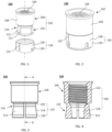
FIG. 1 is a schematic exploded, perspective view of a fastener having an expansion sleeve in accordance with an embodiment of the present invention; -
FIG. 2 is a schematic isometric view of the fastener ofFIG. 1 after being assembled in accordance with an embodiment of the present invention; -
FIG. 3 is a schematic front view of a main body of the fastener ofFIG. 1 in accordance with an embodiment of the present invention; -
FIG. 4 is a schematic cross-sectional side view of the main body ofFIG. 3 from line A-A in accordance with an embodiment of the present invention; -
FIGS. 5 and 6 are respective top and bottom plan views of the fastener ofFIG. 1 in accordance with an embodiment of the present invention; -
FIG. 7 is a schematic front view of the fastener ofFIG. 1 in accordance with an embodiment of the present invention -
FIG. 8 is a schematic cross-sectional side view of the fastener ofFIG. 7 from line B-B in accordance with an embodiment of the present invention; -
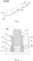
FIG. 9 is a schematic isometric view of a partially-formed expansion sleeve in accordance with an embodiment of the present invention; -
FIG. 10 is a schematic cross-sectional side view of the fastener ofFIG. 1 that is installed into a hole of a target structure in accordance with an embodiment of the present invention; -
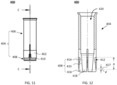
FIG. 11 is a schematic front view of a fastener having an expansion sleeve in accordance with another embodiment of the present invention; and -
FIG. 12 is a schematic cross-sectional side view of the fastener ofFIG. 11 from line C-C in accordance with an embodiment of the present invention. - The detailed description set forth below in connection with the appended drawings is intended as a description of presently preferred embodiments of the invention, and is not intended to represent the only forms in which the present invention may be practised. It is to be understood that the same or equivalent functions may be accomplished by different embodiments that are intended to be encompassed within the spirit and scope of the invention. In the drawings, like numerals are used to indicate like elements throughout. Furthermore, terms "comprises," "comprising," or any other variation thereof, are intended to cover a non-exclusive inclusion, such that module, circuit, device components, structures and method steps that comprises a list of elements or steps does not include only those elements but may include other elements or steps not expressly listed or inherent to such module, circuit, device components or steps. An element or step proceeded by "comprises ... a" does not, without more constraints, preclude the existence of additional identical elements or steps that comprises the element or step.
- Referring now to
FIGS. 1 and 2 , schematic exploded and assembled perspective views of afastener 100 in accordance with an embodiment of the present invention are shown. Thefastener 100 comprises amain body 102 with a throughhole 104 longitudinally formed therein. Themain body 102 includes atubular portion 106 definingwalls 108 that surround an upper part of the throughhole 104, and asplit portion 110 extending from a lower end of thetubular portion 106 with a free distal end facing away from thetubular portion 106. In a preferred embodiment, thesplit portion 110 comprises at least twoexpansible members 112 annularly surrounding a lower part of thethrough hole 104. In a preferred embodiment, theexpansible members 112 integrally extend from lower ends of thewalls 108. In a preferred embodiment, two adjacentexpansible members 112 are spaced by agap 113. -
FIGS. 3 is a schematic front view of amain body 102 of the fastener ofFIG. 1 in accordance with an embodiment of the present invention, andFIG. 4 is a schematic cross-sectional side view of themain body 102 ofFIG. 3 from line A-A. In a preferred embodiment, thesplit portion 110 longitudinally comprises atapered section 114 that tapers in a direction towards thetubular portion 106. Thetapered section 114 is preferably truncated-conical shaped. In a preferred embodiment, the tapered section defines an externalannular recess 116 surrounding thesplit portion 108. In a preferred embodiment, an outer diameter of an upper end of the taperedsection 114 is less than an outer diameter of the lower end of thetubular portion 106, which forms the externalannular recess 116. In a preferred embodiment, an outer diameter of the lower end of the taperedsection 114 is equal to or less than an outer diameter of thetubular portion 106. In a preferred embodiment, thegap 113 longitudinally extends from the upper end of the taperedsection 114 to the free distal end of thesplit portion 110. - In a preferred embodiment, the
split portion 110 also comprises aneck section 118 located between thetubular portion 106 and the taperedsection 114, wherein a minimum outer diameter of theneck section 118 is less than the outer diameter of the lower end of thetubular portion 106. In a preferred embodiment, a height of theneck section 118 is less than a height of the taperedsection 114. In a preferred embodiment, the height of theneck section 118 is 1/8-1/3 of the height of the taperedsection 114. In a preferred embodiment, thetubular portion 106, theneck section 118 and the taperedsection 114 are co-axial and integrally formed. In another preferred embodiment, the taperedsection 114 directly integrally extends from the lower end of thetubular portion 106. - In a preferred embodiment, the
split portion 110 further comprises abase section 120 extending from the lower end of the taperedsection 114 with an outer diameter of an upper end thereof equal to the outer diameter of the lower end of the taperedsection 114. In a preferred embodiment, thebase section 120 is substantially cylindrical-shaped. In another preferred embodiment, thebase section 120 tapers in a direction towards the taperedsection 114 with a taper less than a taper of the taperedsection 114. In a preferred embodiment, thebase section 120 and the taperedsection 114 are co-axial and integrally formed. In a preferred embodiment, a height of thebase section 120 is 1/6-1/3 of a height of the taperedsection 114. - As shown in
FIG. 4 , theupper part 122 of the throughhole 104 is threaded for engaging a threaded male member, such as a bolt, or a threaded rod. In a preferred embodiment, thelower part 124 of the throughhole 104 tapers in a direction away from theupper part 122 of the throughhole 104 such that theexpansible members 112 expand outwardly when a plug is inserted from theupper part 122 into thelower part 124 of the through hole. In a preferred embodiment, themain body 102 is integrally formed from a raw metal material by cold forming or machining. - Referring back to
FIGS. 1 and 2 , thefastener 100 further comprises anexpansion sleeve 126 disposed annularly about thesplit portion 110 and at least partially received in the externalannular recess 116. Theexpansion sleeve 126 comprises aring portion 128 annularly surrounding thesplit portion 110, and a plurality ofexpansion segments 130 disposed along and integrally extending from thering portion 128 towards the free distal end of thesplit portion 110. In a preferred embodiment, thering portion 128 is C-shaped and annularly surrounds thesplit portion 110. -
FIGS. 5 and 6 are respective top and bottom plan views of the fastener ofFIG. 1 in accordance with an embodiment of the present invention. In a preferred embodiment, thesplit portion 110 comprises fourexpansible members 112 substantially evenly distribute around the throughhole 104. In a preferred embodiment, theexpansion sleeve 126 comprises fourexpansible segments 130 substantially evenly distribute around the throughhole 104. However, the number of theexpansible members 112 or theexpansible segments 130 is not limited to four, and the numbers of theexpansible members 112 and theexpansible segments 130 are not necessarily to be identical. -
FIG. 7 is a schematic front view of the fastener ofFIG. 1 in accordance with an embodiment of the present invention, andFIG. 8 is a schematic cross-sectional side view of the fastener ofFIG. 7 from line B-B in accordance with an embodiment of the present invention. In a preferred embodiment, theexpansion sleeve 126 longitudinally extends from the lower end of thetubular portion 106 to the lower end of the taperedsection 114, for example, theexpansion sleeve 126 longitudinally extends across the taperedsection 114. In another preferred embodiment, theexpansible segments 130 longitudinally extend beyond the lower end of the taperedsection 114 and annularly surround thebase section 120 of thesplit portion 110. In a preferred embodiment, theexpansion sleeve 126 longitudinally covers no less than 1/3 of the height of thebase section 120. In yet another preferred embodiment, theexpansible segments 130 longitudinally extends to a lower end of thebase section 120. - In a preferred embodiment, the
expansion sleeve 126 is substantially cylindrical shaped. In a preferred embodiment, an outer diameter of theexpansion sleeve 126 is no less than the outer diameter of thetubular portion 106. In a preferred embodiment, a radial thickness of theexpansion sleeve 126 gradually gets thinner from thering portion 128 to free distal ends of theexpansible segments 130, and an inner surface of theexpansion sleeve 126 inclines and mates with a side surface of the taperedsection 114. - With reference to
FIG. 9 , a schematic isometric view of a partially-formedexpansion sleeve 126 in accordance with an embodiment of the present invention is shown. In a preferred embodiment, theexpansion sleeve 126 is formed by rolling a stampedmetal strip 200 around thesplit portion 110 of themain body 102. Themetal strip 200 is cut off from a metal sheet material preferably by stamping or punching, whereinnotches 202 with an inverted "U" shape or inverted "V" shape are formed along a side of themetal strip 200 by punching or cutting to form theexpansible segments 130. In a preferred embodiment, anupper surface 204 of themetal strip 200 is substantially flat, while an oppositelower surface 206 of themetal strip 200 is inclined with respect to theupper surface 204, such that a thickness of themetal strip 200 gradually gets thinner from thering portion 128 to the free distal ends of theexpansible segments 130. After rolling themetal strip 200 around thesplit portion 110 to form theexpansion sleeve 126, theexpansion sleeve 126 is at least partially received in the externalannular recess 116, and an inner surface of theexpansion sleeve 126, i.e. thelower surface 206 of themetal strip 200, mates with the side surface of the taperedsection 114. - Referring back to
FIGS. 1 and 2 , in another preferred embodiment, theexpansion sleeve 126 can also be formed by machining. Aslit 132 is formed for clamping theexpansion sleeve 126 to thesplit portion 110. -
FIG. 10 is a schematic cross-sectional side view of thefastener 100 ofFIG. 1 that is installed into a hole of a target structure 300 in accordance with an embodiment of the present invention. Theexpansion segments 130 of theexpansion sleeve 126 are expanded outwardly by theexpansible members 112 when aplug 302 is inserted into thelower part 124 of the throughhole 104. Abolt 304 is threaded into theupper part 122 of the throughhole 104 for hanging objects to the target structure 300. As shown inFIG. 10 , theexpansion segments 130 longitudinally extend to the lower end of the taperedsection 114, where a greater expansion force is generated, which achieves a tight engagement between theexpansion sleeve 126 and the target structure 300. - In addition, since the entire
tapered section 114 is longitudinally covered by theexpansion sleeve 126, when thefastener 100 is pulled outward, the taperedsection 114 will not be stopped by the lower edge of theexpansion sleeve 126 and there is no significant friction between themain body 102 and walls of the hole. The smooth relative sliding between themain body 102 and theexpansion sleeve 126 results in a sustained expansion of theexpansion sleeve 126, which ensures a reliable locking engagement between thefastener 100 and the target structure 300 when there are cracks in the target structure 300 or under seismic conditions. - Referring to
FIG. 11 , a schematic front view of afastener 400 having anexpansion sleeve 402 in accordance with another embodiment of the present invention is shown. Similar to thefastener 100 ofFIG. 1 , thefastener 400 includes amain body 404 having atubular portion 406 and asplit portion 408, wherein thesplit portion 408 longitudinally includes a taperedsection 410 that tapers in a direction towards thetubular portion 406. -
FIG. 12 is a schematic cross-sectional side view of the fastener ofFIG. 11 from line C-C in accordance with an embodiment of the present invention. The taperedsection 410 defines an externalannular recess 412 surrounding thesplit portion 408, wherein theexpansion sleeve 402 annularly surrounds thesplit portion 408 and is at least partially received in therecess 412. Similar to thefastener 100 ofFIG. 1 , in a preferred embodiment, thesplit portion 408 further includes aneck section 414 between thetubular portion 406 and the taperedsection 410, and abase section 416 extending from a lower end of the taperedsection 410. In a preferred embodiment, there is a longitudinal distance d between a lower end of theexpansion sleeve 402 and the lower end of the taperedsection 410 of thesplit portion 408. In a preferred embodiment, the longitudinal distance d between the lower end of theexpansion sleeve 402 and the lower end of the taperedsection 410 is equal to or less than 150 of a longitudinal distance h between an upper end of therecess 412 and the lower end of the taperedsection 410. In another preferred embodiment, the longitudinal distance d between the lower end of theexpansion sleeve 402 and the lower end of the taperedsection 410 is equal to or less than 10% of the longitudinal distance h between the upper end of therecess 412 and the lower end of the taperedsection 410. - The description of the preferred embodiments of the present invention has been presented for purposes of illustration and description, but is not intended to be exhaustive or to limit the invention to the forms disclosed. It will be appreciated by those skilled in the art that changes could be made to the embodiments described above without departing from the broad inventive concept thereof. It is understood, therefore, that this invention is not limited to the particular embodiment disclosed, but covers modifications within the scope of the present invention as defined by the appended claims.
Claims (10)
- A fastener (100), comprises:a main body (102) with a through hole (104) longitudinally formed therein, comprising:a tubular portion (106) that defines walls (108) surrounding an upper part of the through hole, anda split portion (110) that extends from a lower end of the tubular portion with a free distal end facing away from the tubular portion (106), wherein the split portion (110) longitudinally comprises a tapered section (114) that tapers in a direction towards the tubular portion (106);andan expansion sleeve (126) annularly surrounding the split portion (110), wherein the expansion sleeve (126) longitudinally extends to a lower end of the tapered section (114), at most to the free distal end of the split portion (110);wherein the split portion (110)further comprises a base section (120) extending from the lower end of the tapered section (114), wherein the base section (120) is cylindrical-shaped, or tapers in a direction towards the tapered section (114) with a taper less than a taper of the tapered section (114), the outer diameter of an upper end of the base section (120) equals to the outer diameter of the lower end of the tapered section (114).
- The fastener of claim 1, wherein the tapered section (114)defines an external annular recess(116)surrounding the split portion (110), and the expansion sleeve (126)is at least partially received in the external annular recess (116, 412).
- The fastener of claim 1, wherein the expansion sleeve (126)comprises a ring portion (128) annularly surrounding the main body (102), and a plurality of expansion segments (130) disposed along and extending from the ring portion (128) towards the lower end of the tapered section (114), wherein the split portion(110)comprises at least two expansible members (112) annularly surrounding a lower part of the through hole (104), and the expansion segments (130) are outwardly expansible by expansion of the expansible members (112).
- The fastener of claim 1, wherein an outer diameter of an upper end of the tapered section (114) is less than an outer diameter of the lower end of the tubular portion (106).
- The fastener of claim 4, wherein the split portion (110) further comprises a neck section (118) located between the tubular portion (106) and the tapered section (114), wherein a minimum outer diameter of the neck section (118) is less than the outer diameter of the lower end of the tubular portion (114).
- The fastener of claim 1, wherein the expansion sleeve (126) longitudinally extends beyond the lower end of the tapered section (114) and annularly surrounds the base section (120).
- The fastener of claim 6, wherein the expansion sleeve (126) longitudinally extends to a lower end of the base section (120).
- The fastener of claim 1, wherein the expansion sleeve (126) is cylindrical shaped, and an inner surface of the expansion sleeve (126) is inclined inwardly and mates with a side surface of the tapered section (114).
- The fastener of claim 1, wherein the expansion sleeve comprises a longitudinal slit (132).
- The fastener of claim 1, wherein the expansion sleeve (126) is formed by rolling a stamped metal strip (200) around the split portion (110).
Applications Claiming Priority (2)
| Application Number | Priority Date | Filing Date | Title |
|---|---|---|---|
| CN201711466724.5A CN109989974A (en) | 2017-12-29 | 2017-12-29 | Fastener |
| PCT/EP2018/083252 WO2019129460A1 (en) | 2017-12-29 | 2018-12-03 | Fastener |
Publications (3)
| Publication Number | Publication Date |
|---|---|
| EP3732380A1 EP3732380A1 (en) | 2020-11-04 |
| EP3732380B1 true EP3732380B1 (en) | 2024-05-08 |
| EP3732380C0 EP3732380C0 (en) | 2024-05-08 |
Family
ID=64661326
Family Applications (1)
| Application Number | Title | Priority Date | Filing Date |
|---|---|---|---|
| EP18815590.7A Active EP3732380B1 (en) | 2017-12-29 | 2018-12-03 | Fastener |
Country Status (7)
| Country | Link |
|---|---|
| US (1) | US11859647B2 (en) |
| EP (1) | EP3732380B1 (en) |
| JP (1) | JP7050935B2 (en) |
| CN (2) | CN109989974A (en) |
| MX (1) | MX2020006767A (en) |
| TW (1) | TWI831757B (en) |
| WO (1) | WO2019129460A1 (en) |
Families Citing this family (4)
| Publication number | Priority date | Publication date | Assignee | Title |
|---|---|---|---|---|
| WO2020045348A1 (en) * | 2018-08-27 | 2020-03-05 | 雄治 土肥 | Expansion-type anchor, sleeve used in same, and construction method |
| US20240369090A1 (en) * | 2021-04-30 | 2024-11-07 | A&S System Co., Ltd. | Anchor bolt |
| EP4575238A1 (en) | 2023-12-19 | 2025-06-25 | Hilti Aktiengesellschaft | Anchor system with dumbbell-shaped anchor rod |
| EP4575239A1 (en) | 2023-12-21 | 2025-06-25 | Hilti Aktiengesellschaft | Anchor system with shear absorbance sleeve |
Citations (2)
| Publication number | Priority date | Publication date | Assignee | Title |
|---|---|---|---|---|
| JP2000230279A (en) * | 1999-02-10 | 2000-08-22 | Mizutani Kogyo Kk | Double expansion structure anchor |
| US8974163B2 (en) * | 2008-09-09 | 2015-03-10 | Mechanical Plastics Corp. | Wedge-type drop-in anchor assembly |
Family Cites Families (21)
| Publication number | Priority date | Publication date | Assignee | Title |
|---|---|---|---|---|
| US1806640A (en) * | 1926-06-12 | 1931-05-26 | Edward Ogden Company J | Expansion shield |
| US2292467A (en) * | 1937-10-22 | 1942-08-11 | Norsell Knut Birger | Means for anchoring pins into metallic members |
| US3523482A (en) * | 1969-02-07 | 1970-08-11 | Mc Donnell Douglas Corp | Anchor |
| DE3006480A1 (en) * | 1980-02-21 | 1981-08-27 | Rehm, Gallus, Prof.Dr.-Ing., 8000 München | Anchor bush with radially flexible segments - is expanded by installation taper and anchor screw assembly |
| DE3770165D1 (en) * | 1987-05-14 | 1991-06-20 | Maechtle Gmbh | SPREADING DOWEL FOR ACHIEVED ANCHORING IN A HOLE. |
| US4917552A (en) * | 1989-09-05 | 1990-04-17 | Diversified Fastening Systems, Inc. | Pin drive anchor with locking sleeve |
| JPH0739747B2 (en) * | 1990-06-20 | 1995-05-01 | 有限会社吉野精機 | Anchor member |
| US5816759A (en) | 1997-05-08 | 1998-10-06 | Illinois Tool Works Inc. | Expansion anchor and method therefor |
| DE19849202A1 (en) * | 1998-10-26 | 2000-04-27 | Hilti Ag | Expansion sleeve |
| DE10038615A1 (en) * | 2000-08-08 | 2002-02-21 | Fischer Artur Werke Gmbh | expansion anchor |
| DE10061808A1 (en) * | 2000-12-12 | 2002-06-13 | Hilti Ag | Fastener for concrete |
| CN2462129Y (en) * | 2001-01-15 | 2001-11-28 | 程功 | Flat head inner thrust rod expansion sleeve screw |
| DE20303806U1 (en) * | 2003-03-11 | 2004-07-22 | Fischerwerke Artur Fischer Gmbh & Co. Kg | Expansion anchor made of metal |
| JP2006016952A (en) * | 2004-05-31 | 2006-01-19 | 寛治 ▲魚▼谷 | Anchor, method for temporarily fixing it, and temporary fixing structure using the same |
| KR20070077512A (en) * | 2007-07-07 | 2007-07-26 | 송재섭 | Anchor set anchor. |
| DE102009045345A1 (en) | 2009-10-06 | 2011-04-07 | Hilti Aktiengesellschaft | expansion anchor |
| EP2395247A1 (en) * | 2010-06-10 | 2011-12-14 | Powers Products III, LLC | Drop-in anchor and drop-in anchor systems |
| CN102192224A (en) * | 2010-12-10 | 2011-09-21 | 上海康驰建筑技术有限公司 | Anchor bolt and anchoring method matched with anchor bolt |
| EP2876311A1 (en) | 2013-11-25 | 2015-05-27 | HILTI Aktiengesellschaft | Expansion anchor with swelling element for sleeve fixing |
| JP6584890B2 (en) * | 2015-09-17 | 2019-10-02 | Jr東日本コンサルタンツ株式会社 | Anchor bolt with reverse rotation prevention mechanism |
| CN206206348U (en) * | 2016-09-29 | 2017-05-31 | 鹏驰五金制品有限公司 | Urgent expansion bolt in a kind of |
-
2017
- 2017-12-29 CN CN201711466724.5A patent/CN109989974A/en active Pending
-
2018
- 2018-11-26 TW TW107142018A patent/TWI831757B/en active
- 2018-12-03 CN CN201880084356.4A patent/CN111512054B/en active Active
- 2018-12-03 EP EP18815590.7A patent/EP3732380B1/en active Active
- 2018-12-03 WO PCT/EP2018/083252 patent/WO2019129460A1/en not_active Ceased
- 2018-12-03 JP JP2020534296A patent/JP7050935B2/en active Active
- 2018-12-03 MX MX2020006767A patent/MX2020006767A/en unknown
- 2018-12-03 US US16/958,352 patent/US11859647B2/en active Active
Patent Citations (2)
| Publication number | Priority date | Publication date | Assignee | Title |
|---|---|---|---|---|
| JP2000230279A (en) * | 1999-02-10 | 2000-08-22 | Mizutani Kogyo Kk | Double expansion structure anchor |
| US8974163B2 (en) * | 2008-09-09 | 2015-03-10 | Mechanical Plastics Corp. | Wedge-type drop-in anchor assembly |
Also Published As
| Publication number | Publication date |
|---|---|
| CN111512054B (en) | 2026-02-03 |
| WO2019129460A1 (en) | 2019-07-04 |
| MX2020006767A (en) | 2020-08-24 |
| CN109989974A (en) | 2019-07-09 |
| US20210062846A1 (en) | 2021-03-04 |
| JP2021507191A (en) | 2021-02-22 |
| EP3732380A1 (en) | 2020-11-04 |
| TW201930738A (en) | 2019-08-01 |
| JP7050935B2 (en) | 2022-04-08 |
| US11859647B2 (en) | 2024-01-02 |
| TWI831757B (en) | 2024-02-11 |
| EP3732380C0 (en) | 2024-05-08 |
| CN111512054A (en) | 2020-08-07 |
Similar Documents
| Publication | Publication Date | Title |
|---|---|---|
| US11859647B2 (en) | Fastener | |
| US5074726A (en) | Blind fastener | |
| US4692076A (en) | Expansion dowel with anchored state indicator | |
| US9970467B2 (en) | Handheld power tool | |
| US7306418B2 (en) | Deforming member and captive fastener retaining method | |
| EP2947336A1 (en) | Blind nut | |
| US9897129B2 (en) | Captive floating flare nut | |
| MXPA06001686A (en) | Fastener, method of attaching a fastener to a panel and fastener and panel assembly. | |
| TW201122248A (en) | Nut with lug flare | |
| US4634326A (en) | Expansion anchor | |
| US5346348A (en) | Self-plugging blind fastener | |
| EP3845716A1 (en) | Expansion-type anchor, sleeve used in same, and construction method | |
| US3018684A (en) | Wire coil thread connection in soft materials | |
| US20200108475A1 (en) | Press-in connecting element and method for anchoring press-in connecting elements in a permanently deformable flat metal material or components or workpieces produced therefrom | |
| US3318183A (en) | Expansion anchor | |
| US5458448A (en) | Expansion bolt structure | |
| US3431960A (en) | Threaded fastener with deformable anchoring portion | |
| WO2017019912A2 (en) | Tapered head clinch fastener | |
| HK40032134A (en) | Fastener | |
| HK40032134B (en) | Fastener | |
| WO2022230604A1 (en) | Anchor bolt | |
| US20220112914A1 (en) | Fastening Unit | |
| GB2199914A (en) | Blind fastener device | |
| EP0158304A1 (en) | Fastener | |
| EP0333202B1 (en) | Blind fastener |
Legal Events
| Date | Code | Title | Description |
|---|---|---|---|
| STAA | Information on the status of an ep patent application or granted ep patent |
Free format text: STATUS: UNKNOWN |
|
| STAA | Information on the status of an ep patent application or granted ep patent |
Free format text: STATUS: THE INTERNATIONAL PUBLICATION HAS BEEN MADE |
|
| PUAI | Public reference made under article 153(3) epc to a published international application that has entered the european phase |
Free format text: ORIGINAL CODE: 0009012 |
|
| STAA | Information on the status of an ep patent application or granted ep patent |
Free format text: STATUS: REQUEST FOR EXAMINATION WAS MADE |
|
| 17P | Request for examination filed |
Effective date: 20200729 |
|
| AK | Designated contracting states |
Kind code of ref document: A1 Designated state(s): AL AT BE BG CH CY CZ DE DK EE ES FI FR GB GR HR HU IE IS IT LI LT LU LV MC MK MT NL NO PL PT RO RS SE SI SK SM TR |
|
| AX | Request for extension of the european patent |
Extension state: BA ME |
|
| REG | Reference to a national code |
Ref country code: HK Ref legal event code: DE Ref document number: 40032134 Country of ref document: HK |
|
| DAV | Request for validation of the european patent (deleted) | ||
| DAX | Request for extension of the european patent (deleted) | ||
| STAA | Information on the status of an ep patent application or granted ep patent |
Free format text: STATUS: EXAMINATION IS IN PROGRESS |
|
| 17Q | First examination report despatched |
Effective date: 20211006 |
|
| GRAP | Despatch of communication of intention to grant a patent |
Free format text: ORIGINAL CODE: EPIDOSNIGR1 |
|
| STAA | Information on the status of an ep patent application or granted ep patent |
Free format text: STATUS: GRANT OF PATENT IS INTENDED |
|
| INTG | Intention to grant announced |
Effective date: 20240208 |
|
| GRAS | Grant fee paid |
Free format text: ORIGINAL CODE: EPIDOSNIGR3 |
|
| GRAA | (expected) grant |
Free format text: ORIGINAL CODE: 0009210 |
|
| STAA | Information on the status of an ep patent application or granted ep patent |
Free format text: STATUS: THE PATENT HAS BEEN GRANTED |
|
| AK | Designated contracting states |
Kind code of ref document: B1 Designated state(s): AL AT BE BG CH CY CZ DE DK EE ES FI FR GB GR HR HU IE IS IT LI LT LU LV MC MK MT NL NO PL PT RO RS SE SI SK SM TR |
|
| REG | Reference to a national code |
Ref country code: GB Ref legal event code: FG4D |
|
| REG | Reference to a national code |
Ref country code: CH Ref legal event code: EP |
|
| REG | Reference to a national code |
Ref country code: DE Ref legal event code: R096 Ref document number: 602018069324 Country of ref document: DE |
|
| REG | Reference to a national code |
Ref country code: IE Ref legal event code: FG4D |
|
| U01 | Request for unitary effect filed |
Effective date: 20240508 |
|
| U07 | Unitary effect registered |
Designated state(s): AT BE BG DE DK EE FI FR IT LT LU LV MT NL PT SE SI Effective date: 20240522 |
|
| PG25 | Lapsed in a contracting state [announced via postgrant information from national office to epo] |
Ref country code: IS Free format text: LAPSE BECAUSE OF FAILURE TO SUBMIT A TRANSLATION OF THE DESCRIPTION OR TO PAY THE FEE WITHIN THE PRESCRIBED TIME-LIMIT Effective date: 20240908 |
|
| PG25 | Lapsed in a contracting state [announced via postgrant information from national office to epo] |
Ref country code: HR Free format text: LAPSE BECAUSE OF FAILURE TO SUBMIT A TRANSLATION OF THE DESCRIPTION OR TO PAY THE FEE WITHIN THE PRESCRIBED TIME-LIMIT Effective date: 20240508 |
|
| PG25 | Lapsed in a contracting state [announced via postgrant information from national office to epo] |
Ref country code: GR Free format text: LAPSE BECAUSE OF FAILURE TO SUBMIT A TRANSLATION OF THE DESCRIPTION OR TO PAY THE FEE WITHIN THE PRESCRIBED TIME-LIMIT Effective date: 20240809 |
|
| PG25 | Lapsed in a contracting state [announced via postgrant information from national office to epo] |
Ref country code: ES Free format text: LAPSE BECAUSE OF FAILURE TO SUBMIT A TRANSLATION OF THE DESCRIPTION OR TO PAY THE FEE WITHIN THE PRESCRIBED TIME-LIMIT Effective date: 20240508 |
|
| PG25 | Lapsed in a contracting state [announced via postgrant information from national office to epo] |
Ref country code: PL Free format text: LAPSE BECAUSE OF FAILURE TO SUBMIT A TRANSLATION OF THE DESCRIPTION OR TO PAY THE FEE WITHIN THE PRESCRIBED TIME-LIMIT Effective date: 20240508 |
|
| PG25 | Lapsed in a contracting state [announced via postgrant information from national office to epo] |
Ref country code: PL Free format text: LAPSE BECAUSE OF FAILURE TO SUBMIT A TRANSLATION OF THE DESCRIPTION OR TO PAY THE FEE WITHIN THE PRESCRIBED TIME-LIMIT Effective date: 20240508 Ref country code: NO Free format text: LAPSE BECAUSE OF FAILURE TO SUBMIT A TRANSLATION OF THE DESCRIPTION OR TO PAY THE FEE WITHIN THE PRESCRIBED TIME-LIMIT Effective date: 20240808 Ref country code: IS Free format text: LAPSE BECAUSE OF FAILURE TO SUBMIT A TRANSLATION OF THE DESCRIPTION OR TO PAY THE FEE WITHIN THE PRESCRIBED TIME-LIMIT Effective date: 20240908 Ref country code: HR Free format text: LAPSE BECAUSE OF FAILURE TO SUBMIT A TRANSLATION OF THE DESCRIPTION OR TO PAY THE FEE WITHIN THE PRESCRIBED TIME-LIMIT Effective date: 20240508 Ref country code: GR Free format text: LAPSE BECAUSE OF FAILURE TO SUBMIT A TRANSLATION OF THE DESCRIPTION OR TO PAY THE FEE WITHIN THE PRESCRIBED TIME-LIMIT Effective date: 20240809 Ref country code: ES Free format text: LAPSE BECAUSE OF FAILURE TO SUBMIT A TRANSLATION OF THE DESCRIPTION OR TO PAY THE FEE WITHIN THE PRESCRIBED TIME-LIMIT Effective date: 20240508 Ref country code: RS Free format text: LAPSE BECAUSE OF FAILURE TO SUBMIT A TRANSLATION OF THE DESCRIPTION OR TO PAY THE FEE WITHIN THE PRESCRIBED TIME-LIMIT Effective date: 20240808 |
|
| PG25 | Lapsed in a contracting state [announced via postgrant information from national office to epo] |
Ref country code: CZ Free format text: LAPSE BECAUSE OF FAILURE TO SUBMIT A TRANSLATION OF THE DESCRIPTION OR TO PAY THE FEE WITHIN THE PRESCRIBED TIME-LIMIT Effective date: 20240508 |
|
| PG25 | Lapsed in a contracting state [announced via postgrant information from national office to epo] |
Ref country code: SK Free format text: LAPSE BECAUSE OF FAILURE TO SUBMIT A TRANSLATION OF THE DESCRIPTION OR TO PAY THE FEE WITHIN THE PRESCRIBED TIME-LIMIT Effective date: 20240508 Ref country code: RO Free format text: LAPSE BECAUSE OF FAILURE TO SUBMIT A TRANSLATION OF THE DESCRIPTION OR TO PAY THE FEE WITHIN THE PRESCRIBED TIME-LIMIT Effective date: 20240508 |
|
| PG25 | Lapsed in a contracting state [announced via postgrant information from national office to epo] |
Ref country code: SM Free format text: LAPSE BECAUSE OF FAILURE TO SUBMIT A TRANSLATION OF THE DESCRIPTION OR TO PAY THE FEE WITHIN THE PRESCRIBED TIME-LIMIT Effective date: 20240508 |
|
| PG25 | Lapsed in a contracting state [announced via postgrant information from national office to epo] |
Ref country code: SM Free format text: LAPSE BECAUSE OF FAILURE TO SUBMIT A TRANSLATION OF THE DESCRIPTION OR TO PAY THE FEE WITHIN THE PRESCRIBED TIME-LIMIT Effective date: 20240508 Ref country code: SK Free format text: LAPSE BECAUSE OF FAILURE TO SUBMIT A TRANSLATION OF THE DESCRIPTION OR TO PAY THE FEE WITHIN THE PRESCRIBED TIME-LIMIT Effective date: 20240508 Ref country code: RO Free format text: LAPSE BECAUSE OF FAILURE TO SUBMIT A TRANSLATION OF THE DESCRIPTION OR TO PAY THE FEE WITHIN THE PRESCRIBED TIME-LIMIT Effective date: 20240508 Ref country code: CZ Free format text: LAPSE BECAUSE OF FAILURE TO SUBMIT A TRANSLATION OF THE DESCRIPTION OR TO PAY THE FEE WITHIN THE PRESCRIBED TIME-LIMIT Effective date: 20240508 |
|
| U20 | Renewal fee for the european patent with unitary effect paid |
Year of fee payment: 7 Effective date: 20241227 |
|
| REG | Reference to a national code |
Ref country code: DE Ref legal event code: R097 Ref document number: 602018069324 Country of ref document: DE |
|
| PLBE | No opposition filed within time limit |
Free format text: ORIGINAL CODE: 0009261 |
|
| STAA | Information on the status of an ep patent application or granted ep patent |
Free format text: STATUS: NO OPPOSITION FILED WITHIN TIME LIMIT |
|
| 26N | No opposition filed |
Effective date: 20250211 |
|
| PG25 | Lapsed in a contracting state [announced via postgrant information from national office to epo] |
Ref country code: MC Free format text: LAPSE BECAUSE OF FAILURE TO SUBMIT A TRANSLATION OF THE DESCRIPTION OR TO PAY THE FEE WITHIN THE PRESCRIBED TIME-LIMIT Effective date: 20240508 |
|
| PG25 | Lapsed in a contracting state [announced via postgrant information from national office to epo] |
Ref country code: IE Free format text: LAPSE BECAUSE OF NON-PAYMENT OF DUE FEES Effective date: 20241203 |
|
| REG | Reference to a national code |
Ref country code: CH Ref legal event code: U11 Free format text: ST27 STATUS EVENT CODE: U-0-0-U10-U11 (AS PROVIDED BY THE NATIONAL OFFICE) Effective date: 20260101 |
|
| PGFP | Annual fee paid to national office [announced via postgrant information from national office to epo] |
Ref country code: GB Payment date: 20251219 Year of fee payment: 8 |
|
| U20 | Renewal fee for the european patent with unitary effect paid |
Year of fee payment: 8 Effective date: 20251230 |
|
| PG25 | Lapsed in a contracting state [announced via postgrant information from national office to epo] |
Ref country code: CY Free format text: LAPSE BECAUSE OF FAILURE TO SUBMIT A TRANSLATION OF THE DESCRIPTION OR TO PAY THE FEE WITHIN THE PRESCRIBED TIME-LIMIT; INVALID AB INITIO Effective date: 20181203 |
|
| PGFP | Annual fee paid to national office [announced via postgrant information from national office to epo] |
Ref country code: CH Payment date: 20260101 Year of fee payment: 8 |
|
| PG25 | Lapsed in a contracting state [announced via postgrant information from national office to epo] |
Ref country code: TR Free format text: LAPSE BECAUSE OF FAILURE TO SUBMIT A TRANSLATION OF THE DESCRIPTION OR TO PAY THE FEE WITHIN THE PRESCRIBED TIME-LIMIT Effective date: 20240508 |
|
| PG25 | Lapsed in a contracting state [announced via postgrant information from national office to epo] |
Ref country code: HU Free format text: LAPSE BECAUSE OF FAILURE TO SUBMIT A TRANSLATION OF THE DESCRIPTION OR TO PAY THE FEE WITHIN THE PRESCRIBED TIME-LIMIT; INVALID AB INITIO Effective date: 20181203 |