EP3731982B1 - Multi-layer blanking process for manufacturing metal parts - Google Patents
Multi-layer blanking process for manufacturing metal parts Download PDFInfo
- Publication number
- EP3731982B1 EP3731982B1 EP18803543.0A EP18803543A EP3731982B1 EP 3731982 B1 EP3731982 B1 EP 3731982B1 EP 18803543 A EP18803543 A EP 18803543A EP 3731982 B1 EP3731982 B1 EP 3731982B1
- Authority
- EP
- European Patent Office
- Prior art keywords
- blanking
- basic material
- metal parts
- layered basic
- layered
- Prior art date
- Legal status (The legal status is an assumption and is not a legal conclusion. Google has not performed a legal analysis and makes no representation as to the accuracy of the status listed.)
- Active
Links
Images
Classifications
-
- B—PERFORMING OPERATIONS; TRANSPORTING
- B21—MECHANICAL METAL-WORKING WITHOUT ESSENTIALLY REMOVING MATERIAL; PUNCHING METAL
- B21D—WORKING OR PROCESSING OF SHEET METAL OR METAL TUBES, RODS OR PROFILES WITHOUT ESSENTIALLY REMOVING MATERIAL; PUNCHING METAL
- B21D28/00—Shaping by press-cutting; Perforating
- B21D28/02—Punching blanks or articles with or without obtaining scrap; Notching
- B21D28/22—Notching the peripheries of circular blanks, e.g. laminations for dynamo-electric machines
-
- B—PERFORMING OPERATIONS; TRANSPORTING
- B21—MECHANICAL METAL-WORKING WITHOUT ESSENTIALLY REMOVING MATERIAL; PUNCHING METAL
- B21D—WORKING OR PROCESSING OF SHEET METAL OR METAL TUBES, RODS OR PROFILES WITHOUT ESSENTIALLY REMOVING MATERIAL; PUNCHING METAL
- B21D28/00—Shaping by press-cutting; Perforating
- B21D28/02—Punching blanks or articles with or without obtaining scrap; Notching
- B21D28/16—Shoulder or burr prevention, e.g. fine-blanking
-
- B—PERFORMING OPERATIONS; TRANSPORTING
- B21—MECHANICAL METAL-WORKING WITHOUT ESSENTIALLY REMOVING MATERIAL; PUNCHING METAL
- B21D—WORKING OR PROCESSING OF SHEET METAL OR METAL TUBES, RODS OR PROFILES WITHOUT ESSENTIALLY REMOVING MATERIAL; PUNCHING METAL
- B21D35/00—Combined processes according to or processes combined with methods covered by groups B21D1/00 - B21D31/00
- B21D35/002—Processes combined with methods covered by groups B21D1/00 - B21D31/00
- B21D35/005—Processes combined with methods covered by groups B21D1/00 - B21D31/00 characterized by the material of the blank or the workpiece
- B21D35/007—Layered blanks
-
- C—CHEMISTRY; METALLURGY
- C21—METALLURGY OF IRON
- C21D—MODIFYING THE PHYSICAL STRUCTURE OF FERROUS METALS; GENERAL DEVICES FOR HEAT TREATMENT OF FERROUS OR NON-FERROUS METALS OR ALLOYS; MAKING METAL MALLEABLE, e.g. BY DECARBURISATION OR TEMPERING
- C21D1/00—General methods or devices for heat treatment, e.g. annealing, hardening, quenching or tempering
- C21D1/26—Methods of annealing
- C21D1/28—Normalising
-
- C—CHEMISTRY; METALLURGY
- C21—METALLURGY OF IRON
- C21D—MODIFYING THE PHYSICAL STRUCTURE OF FERROUS METALS; GENERAL DEVICES FOR HEAT TREATMENT OF FERROUS OR NON-FERROUS METALS OR ALLOYS; MAKING METAL MALLEABLE, e.g. BY DECARBURISATION OR TEMPERING
- C21D8/00—Modifying the physical properties of ferrous metals or ferrous alloys by deformation combined with, or followed by, heat treatment
- C21D8/12—Modifying the physical properties of ferrous metals or ferrous alloys by deformation combined with, or followed by, heat treatment during manufacturing of articles with special electromagnetic properties
- C21D8/1244—Modifying the physical properties of ferrous metals or ferrous alloys by deformation combined with, or followed by, heat treatment during manufacturing of articles with special electromagnetic properties characterised by the heat treatment
- C21D8/1272—Final recrystallisation annealing
-
- C—CHEMISTRY; METALLURGY
- C21—METALLURGY OF IRON
- C21D—MODIFYING THE PHYSICAL STRUCTURE OF FERROUS METALS; GENERAL DEVICES FOR HEAT TREATMENT OF FERROUS OR NON-FERROUS METALS OR ALLOYS; MAKING METAL MALLEABLE, e.g. BY DECARBURISATION OR TEMPERING
- C21D9/00—Heat treatment, e.g. annealing, hardening, quenching or tempering, adapted for particular articles; Furnaces therefor
- C21D9/0068—Heat treatment, e.g. annealing, hardening, quenching or tempering, adapted for particular articles; Furnaces therefor for particular articles not mentioned below
-
- H—ELECTRICITY
- H02—GENERATION; CONVERSION OR DISTRIBUTION OF ELECTRIC POWER
- H02K—DYNAMO-ELECTRIC MACHINES
- H02K15/00—Processes or apparatus specially adapted for manufacturing, assembling, maintaining or repairing of dynamo-electric machines
- H02K15/02—Processes or apparatus specially adapted for manufacturing, assembling, maintaining or repairing of dynamo-electric machines of stator or rotor bodies
-
- C—CHEMISTRY; METALLURGY
- C21—METALLURGY OF IRON
- C21D—MODIFYING THE PHYSICAL STRUCTURE OF FERROUS METALS; GENERAL DEVICES FOR HEAT TREATMENT OF FERROUS OR NON-FERROUS METALS OR ALLOYS; MAKING METAL MALLEABLE, e.g. BY DECARBURISATION OR TEMPERING
- C21D2261/00—Machining or cutting being involved
Definitions
- the present disclosure relates to a process for the blanking of metal parts, in particular a multi-layer blanking process.
- the blanking process is, as such, generally known and are broadly applied in the manufacturing of metal parts, in particular for the cutting-out thereof from strip, sheet or plate shaped basic material.
- at least the 2D contour of the metal part is shaped by pressing a correspondingly shaped blanking punch against and through the basic material, which basic material is clamped between a blanking die and a blank holder of a blanking device.
- the blanking die and the blank holder thereto define a respective cavity that is shaped to accommodate the blanking punch.
- An edge of the blanking die defining the contour of the cavity thereof carves into and finally completely cuts through the basic material, as such basic material is progressively pressed into the cavity by the movement of the blanking punch relative to the blanking die.
- the above-described blanking process and blanking device are for example used in the manufacture of individual lamina for a laminate, such as rotor and/or stator lamina stacks for electric motors, as described in the US patent number 4,738,020 , or transformer core laminates.
- the electrical efficiency of the electric motor is, at least to a certain extent, inversely proportional to the thickness of the basic material, i.e. of the individual rotor/stator lamina.
- a minimum required thickness applies to the basic material in the blanking process. Otherwise, the basic material may be too thin for the proper handling thereof, e.g. may deform when being supplied to the blanking device. Also, a (too) thin basic material may result in the unwanted deformation of the blanked part, such as a stretching or a local thinning thereof, by the force exerted by the blanking punch. Finally, manufacturing economics plays a limiting role as well. After all, the thinner the individual lamina is, the more lamina have to be manufactured to build a laminate stack of certain height.
- JP-A-2016129902 In order to increase a production rate of the known blanking process, it has been proposed in JP-A-2016129902 to apply a layered basic material therein, i.e. to stack two or more layers of the basic material on top of one another prior to the actual blanking, i.e. cutting thereof. Then, a number of blanked parts can be formed with a single blanking punch in a single blanking stroke that corresponds to the number of layers of the layered basic material.
- a plastic deformation at the cut edges of the thus blanked parts can exceed such deformation obtained in the more conventional blanking process utilizing one layer of basic material only.
- the electrical and/or magnetic properties of the said laminate stack may not be optimal due to such large plastic deformation at the cut edges of the individual lamina.
- plastic deformation disadvantageously decreases the magnetic permeability and/or increases the magnetic hysteresis (losses) of the metal.
- a smaller or larger (air) gap may disadvantageously be present between at least some of the lamina in the laminate stack at or near the cut edges thereof.
- the present invention aims to improve upon the multi-layer blanking process.
- the present invention aims to reduce the plastic deformation at or near the cut edges of the blanked parts that are obtained with such process.
- the basic material is obtained by the cold rolling of stock material to reduce the thickness thereof and thus to work-harden the basic material by crystal grain size refinement and dislocation nucleation.
- an elongation to fracture of the basic material is decreased considerably, i.e. its brittleness is increased.
- a number of layers of the basic material are combined into the layered basic material and metal parts are blanked from the layered basic material.
- the blanked parts are subjected to a so-called normalizing or annealing heat treatment to improve the mechanical, electrical and/or magnetic properties thereof, in particular to decrease brittleness by the so-called recovery and re-crystallization of their metal microstructure.
- the annealing or normalizing heat treatment of steel is typically carried out at a temperature above 650 degrees Celsius, e.g. at about 800 to 1000°C.
- the metal parts are heated to such temperature inductively.
- an edge deformation of the blanked part introduced during the actual blanking, i.e. cutting, thereof is remarkably and favourably reduced, at least relative to when using basic material that is annealed after rolling, but before blanking.
- a thickness of the basic material is defined in the process step of cold rolling at between 5% and 30% of the thickness of the stock material prior to such cold rolling.
- a yield strength of more than 450 MPa, preferably of around 500 MPa, and/or a minimal hardness of more than 210 HV0.1 up to 450 HV0.1, preferably more than 250 HV0.1, more preferably in the range from 300 to 400 HV0.1, are sought after for the basic material in the said cold rolling process, i.e. before the blanking thereof (in particular as compared to a material hardness of up to 200 HV0.1 and a yield strength up to 420 MPa of annealed electrical steel).
- an additional process step of oxidation of a surface layer of the cold rolled, but still non-layered basic material is included therein.
- a relatively high friction is realised between the individual layers of the layered basic material, at least compared to the friction between the (cold) rolled surfaces thereof.
- an observed phenomenon in the multi-layer blanking process of the intermediate layers of the layered basic material being stretched relative to the top and bottom layers thereof, while being pulled and bend into the cavity of the blanking die can be counteracted by the said increased friction between the respective layers and the shape-consistency between all of simultaneously blanked parts can be improved.
- steel oxidises form already at room temperature in air, but such oxidation can of course be accelerated by increasing the process temperature and/or in an oxygen-rich process atmosphere, while keeping well below the minimum annealing temperature of 650 degrees Celsius, e.g. at 600 degrees Centigrade, in order to maintain the presently desired mechanical properties of the cold-rolled basic material.
- this is preferably heated to the oxidation process temperature inductively, e.g. by being gradually fed through an induction coil.
- the oxidation process temperature is preferably maintained only for 60 seconds or less, such that the oxidation process can be easily integrated in the overall process chain of the multi-layer blanking process, in particular just before the stacking of the layers of the basic material that can then be arranged as a continuous process relatively easily.
- this latter heat treatment is carried out under a nitrogen atmosphere that is at least virtually free from hydrogen to avoid the reduction, i.e. removal, of the metal-oxide surface layer thereof.
- the multi-layer blanking process in accordance with the present disclosure is particularly suited for and can favourably make use of layered basic material that is composed of 3 up to 12 or more layers, more preferably 4 to 6 layers.
- the process for blanking metal parts in accordance with the present disclosure can favourably make use of layered basic material that is composed of individual layers, each having a thickness in the range from 0.5 mm down to 0.05 mm or less, more favourably between 0.3 and 0.1 mm.
- the layered basic material used is preferably composed of 4 to 6 layers of between 0.1 and 0.2 mm thickness.
- the overall thickness of the layered basic material should preferably not exceed 2 mm to avoid excessive deformation of the layers thereof. For the same reason, a thickness of the layers should preferably not be less than 0.1 mm.
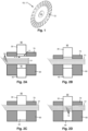
- Figure 1 provides an example of a metal part 10 that can suitably be produced with the aid of a blanking process, in particular the multi-layer blanking process discussed herein.
- the metal part 10 takes the form of a blanked disc 11 provided with a central hole 12 and a series of recesses 13 arranged along its circumference.
- Both the outer and the inner contour of the blanked disc 11 are formed, i.e. are cut out of a basic material, in particular electrical steel, either simultaneously in one cut or in a number of subsequent partial cuts in separate blanking stages.
- This particular type of blanked disc 11 is used in a laminate consisting of many such blanked discs 11 for a rotor of an electric motor.
- the central hole 12 of the blanked discs 11 accommodate a shaft of the rotor and the said recesses 13 thereof accommodate conductive material, such as copper wire windings.
- An electrically isolating layer is typically provided between the individual blanked discs 11 in the rotor laminate to reduce so-called Eddy current losses, typically by coating at least one and preferably both sides thereof in an electrically non-conductive layer, such as a bonding varnish or so-called Backlack.
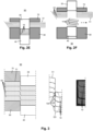
- the figures 2A-2F illustrate a multi-layer blanking process for producing the blanked discs 11 or the metal part 10 in general.
- the figures 2A-2F each represent a simplified cross-section of a blanking device 90 that is used to cut-out such metal parts 10 from a layered basic material 51 comprising two or more (here: four) of mutually stacked strips of basic material 50.
- the blanking device 90 includes a blanking punch 30, a counter punch 40, a blank holder 70 and a blanking die 80.
- the blank holder 70 and the blanking die 80 each define a respective cavity 71, resp. 81, wherein the blanking punch 30 and the counter punch 40 are contained, which cavities 71, 81 are shaped to correspond to (the contour of) the metal part 10.
- This particular type of blanking process/blanking device 90 using a counter punch 40 is known per se, namely as a fine-blanking.
- the blanking device 90 is shown in a first open state, wherein the blanking punch 30 is fully retracted into the blank holder 70, the counter punch 40 is fully retracted into the blanking die 80 and wherein the blank holder 70 and the blanking die 80 are separated from one another, at least sufficiently for allowing the layered basic material 51 to be inserted and/or advanced relative to the blanking device 90, as schematically indicated by the dashed arrow.
- FIG 2B the blanking device 90 is shown after the blank holder 70 and the blanking die 80 have been moved towards each other to clamp the layered basic material 51 between them.
- FIG 2C the blanking device 90 is shown after the blanking punch 30 and the counter punch 40 have been moved towards each other to also clamp the layered basic material 51 between them.
- FIGS 2D and 2E the step of cutting out the metal part 10 from each basic material strip 50 of the layered basic material 51, by the forced movement of the combination of the blanking punch 30 and the counter punch 40 relative to the blanking die 80, is illustrated.
- the blanking device 90 is shown during such cutting-out and in figure 2E the blanking device 90 is shown after the metal parts 10 have been completely cut out, i.e. have been severed from the layered basic material 51, but are still held between the blanking punch 30 and the counter punch 40.
- the blanking device 90 is shown in a second open state, wherein the blanking punch 30 is fully retracted into the blank holder 70 and wherein the counter punch 40 protrudes from the blanking die 80 after pushing the metal parts 10 upwards out of the cavity 81 of the blanking die 80 to allow the extraction thereof from the blanking device 90. After such extraction, the blanking device 90 returns to its first open state shown in figure 2A etc.
- Figure 3 provides a close-up of the multi-layer blanking process and the blanking device 90 applied therein, as well as a cross-section of the cut edges of the metal parts 10 obtained therewith.
- a four layered basic material 51 is applied.
- Figure 3 illustrates the phenomenon that the intermediate layers of the layered basic material 51 are pulled and/or bend into the cavity of the blanking die 40, i.e. plastically deform by the movement of the blanking punch 30 during the actual blanking, i.e. cutting of the layered basic material 51.
- the metal parts 10 show a noticeable plastic deformation at or near the cut edges 100 thereof, i.e. edge deformation ED.
- the former multi-layer blanking process can be improved upon, in particular the edge deformation ED of the metal parts 10 can be reduced, favourably without modifying the chemical composition of the basic material or the above-described construction of the blanking device 90 as such.
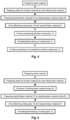
- a novel process chain is provided, whereof a first embodiment is illustrated in figure 4 .
- the basic material is finally prepared to the desired thickness in a first step of the novel multi-layer blanking process by cold rolling.
- a number of layers 50 of the basic material are combined, i.e.
- the layered basic material 51 is supplied to the blanking device 90 and the metal parts 10 are blanked. Since the layered basic material 51 has a work-hardened microstructure, it is relatively brittle and, therefore, less prone to plastic deformation before shearing. Consequently, the said edge deformation in blanking at or near the cut edges of the metal parts 10 is reduced. Thereafter, in a fourth process step of the novel multi-layer blanking process, the metal parts 10 are subjected to the heat treatment of annealing or normalizing to at least reduce brittleness and, more in general, to improve the mechanical, electrical and/or magnetic properties electromagnetic properties thereof. It is noted that annealing with the controlled cooling of the metal parts 10 is typically preferred over normalising with air cooling for achieving optimum results in this latter respect.
- further processing of the metal parts 10, such as deburring, coating, welding etc. can be included in the overall novel process chain, as desired.
- These further processing steps can be included either before or after the said process step of annealing or normalizing, as illustrated in figure 4 .
- the edge deformation ED of the metal parts 10 resulting from the multi-layer blanking process can be further reduced by increasing the friction between the layers 50 of the layered basic material 51.
- an additional process step of oxidising the surface of the basic material 50 is included therein.
- such additional process step of oxidation is included in the novel process chain after the said first process step of cold rolling and before or as part of the said second process step of stacking. After being oxidised the surface of the basic material shows a considerably higher friction between the individual layers 50 of the layered basic material 51, as is desired to reduce the said edge deformation ED.
Landscapes
- Engineering & Computer Science (AREA)
- Chemical & Material Sciences (AREA)
- Mechanical Engineering (AREA)
- Physics & Mathematics (AREA)
- Metallurgy (AREA)
- Thermal Sciences (AREA)
- Crystallography & Structural Chemistry (AREA)
- Materials Engineering (AREA)
- Organic Chemistry (AREA)
- Manufacturing & Machinery (AREA)
- Electromagnetism (AREA)
- Power Engineering (AREA)
- Manufacture Of Motors, Generators (AREA)
- Punching Or Piercing (AREA)
- Manufacturing Cores, Coils, And Magnets (AREA)
Description
- The present disclosure relates to a process for the blanking of metal parts, in particular a multi-layer blanking process. The blanking process is, as such, generally known and are broadly applied in the manufacturing of metal parts, in particular for the cutting-out thereof from strip, sheet or plate shaped basic material. In the known blanking process at least the 2D contour of the metal part is shaped by pressing a correspondingly shaped blanking punch against and through the basic material, which basic material is clamped between a blanking die and a blank holder of a blanking device. The blanking die and the blank holder thereto define a respective cavity that is shaped to accommodate the blanking punch. An edge of the blanking die defining the contour of the cavity thereof, carves into and finally completely cuts through the basic material, as such basic material is progressively pressed into the cavity by the movement of the blanking punch relative to the blanking die.
- In the known blanking process and device, many factors such as a chamfering of the cutting edge of the blanking die, a clearance between an outer contour of the blanking punch and an inner contour of the blanking die defining the cavity, the pressing force exerted by the blanking punch, the thickness and mechanical properties of the basic material, etc., each have their respective influence on the blanking process result, e.g. in terms of the shape accuracy and/or surface quality of the blanked parts.
- The above-described blanking process and blanking device are for example used in the manufacture of individual lamina for a laminate, such as rotor and/or stator lamina stacks for electric motors, as described in the
US patent number 4,738,020 , or transformer core laminates. In relation to this and other known applications of blanked parts, it may be a technical desire to produce the individual blanked parts with a small thickness by using basic material of such small thickness. For example in case of the said electric motor stator or rotor stack, the electrical efficiency of the electric motor is, at least to a certain extent, inversely proportional to the thickness of the basic material, i.e. of the individual rotor/stator lamina. However, in practice, a minimum required thickness applies to the basic material in the blanking process. Otherwise, the basic material may be too thin for the proper handling thereof, e.g. may deform when being supplied to the blanking device. Also, a (too) thin basic material may result in the unwanted deformation of the blanked part, such as a stretching or a local thinning thereof, by the force exerted by the blanking punch. Finally, manufacturing economics plays a limiting role as well. After all, the thinner the individual lamina is, the more lamina have to be manufactured to build a laminate stack of certain height. - In order to increase a production rate of the known blanking process, it has been proposed in
JP-A-2016129902 US-A-5798001 discloses an annealing and/or normalizing heat treatment after the laminations are blanked. - The present invention aims to improve upon the multi-layer blanking process. In particular, the present invention aims to reduce the plastic deformation at or near the cut edges of the blanked parts that are obtained with such process.
- According to the present invention, such aim is realised with the process for blanking metal parts in accordance with the
claim 1 hereinafter. According to the present invention, the basic material is obtained by the cold rolling of stock material to reduce the thickness thereof and thus to work-harden the basic material by crystal grain size refinement and dislocation nucleation. Hereby, an elongation to fracture of the basic material is decreased considerably, i.e. its brittleness is increased. Then a number of layers of the basic material are combined into the layered basic material and metal parts are blanked from the layered basic material. Subsequently, the blanked parts are subjected to a so-called normalizing or annealing heat treatment to improve the mechanical, electrical and/or magnetic properties thereof, in particular to decrease brittleness by the so-called recovery and re-crystallization of their metal microstructure. In particular in case of a steel basic material, such as electrical steel, the annealing or normalizing heat treatment of steel is typically carried out at a temperature above 650 degrees Celsius, e.g. at about 800 to 1000°C. Preferably, the metal parts are heated to such temperature inductively. - By the above novel multi-layer blanking process, an edge deformation of the blanked part introduced during the actual blanking, i.e. cutting, thereof is remarkably and favourably reduced, at least relative to when using basic material that is annealed after rolling, but before blanking. Preferably, a thickness of the basic material is defined in the process step of cold rolling at between 5% and 30% of the thickness of the stock material prior to such cold rolling. Furthermore, in particular in case of a steel basic material, such as electrical steel, a yield strength of more than 450 MPa, preferably of around 500 MPa, and/or a minimal hardness of more than 210 HV0.1 up to 450 HV0.1, preferably more than 250 HV0.1, more preferably in the range from 300 to 400 HV0.1, are sought after for the basic material in the said cold rolling process, i.e. before the blanking thereof (in particular as compared to a material hardness of up to 200 HV0.1 and a yield strength up to 420 MPa of annealed electrical steel).
- In a more detailed embodiment of the novel multi-layer blanking process according to the present disclosure, an additional process step of oxidation of a surface layer of the cold rolled, but still non-layered basic material is included therein. According to the present disclosure, by such oxidised surface layer a relatively high friction is realised between the individual layers of the layered basic material, at least compared to the friction between the (cold) rolled surfaces thereof. By increasing the friction between the layers of the layered basic material, a relative movement there between is favourably inhibited. In particular, an observed phenomenon in the multi-layer blanking process of the intermediate layers of the layered basic material being stretched relative to the top and bottom layers thereof, while being pulled and bend into the cavity of the blanking die, can be counteracted by the said increased friction between the respective layers and the shape-consistency between all of simultaneously blanked parts can be improved. Of course steel oxidises form already at room temperature in air, but such oxidation can of course be accelerated by increasing the process temperature and/or in an oxygen-rich process atmosphere, while keeping well below the minimum annealing temperature of 650 degrees Celsius, e.g. at 600 degrees Centigrade, in order to maintain the presently desired mechanical properties of the cold-rolled basic material. In particular in case of strip shaped basic material, this is preferably heated to the oxidation process temperature inductively, e.g. by being gradually fed through an induction coil. The oxidation process temperature is preferably maintained only for 60 seconds or less, such that the oxidation process can be easily integrated in the overall process chain of the multi-layer blanking process, in particular just before the stacking of the layers of the basic material that can then be arranged as a continuous process relatively easily.
- When the, in this case, surface oxidised, blanked parts are subjected to the normalizing or annealing heat treatment afterwards in accordance with the present disclosure, this latter heat treatment is carried out under a nitrogen atmosphere that is at least virtually free from hydrogen to avoid the reduction, i.e. removal, of the metal-oxide surface layer thereof.
- It is noted that this latter, additional process step of oxidation is particularly effective when producing lamina for rotor, stator or transformer laminates from electrical steel, in particular those containing a/o between 1.5 and 3.5% by weight silicon and less than 0.005% by weight carbon. These types of laminates require the individual lamina thereof to be electrically isolated from one another, which electrical isolation is advantageously realized by the oxidised surface layer thereof as well.
- It is further noted that the multi-layer blanking process in accordance with the present disclosure is particularly suited for and can favourably make use of layered basic material that is composed of 3 up to 12 or more layers, more preferably 4 to 6 layers. Furthermore, the process for blanking metal parts in accordance with the present disclosure can favourably make use of layered basic material that is composed of individual layers, each having a thickness in the range from 0.5 mm down to 0.05 mm or less, more favourably between 0.3 and 0.1 mm. In particular, the layered basic material used is preferably composed of 4 to 6 layers of between 0.1 and 0.2 mm thickness. The overall thickness of the layered basic material should preferably not exceed 2 mm to avoid excessive deformation of the layers thereof. For the same reason, a thickness of the layers should preferably not be less than 0.1 mm.
- In the following, the multi-layer blanking process according to the present disclosure is explained further by way of example embodiments and with reference to the drawings, whereof:
-
Figure 1 is a perspective view of a typical blanked part, being a single lamina made from electrical steel for a stack of lamina, i.e. laminate, for a rotor of an electric motor; -
Figures 2A to 2F schematically illustrate a multi-layer blanking device and process for forming blanked parts; -
Figure 3 provides a schematically drawn detail of thefigures 2D and2E , as well as a photograph of the cut edges of the blanked parts obtained with the multi-layer blanking device and process; -
Figure 4 is a diagrammatic representation of a first embodiment of a novel process chain of the multi-layer blanking process in accordance with the present disclosure; and -
Figure 5 is a diagrammatic representation of a second embodiment of a novel process chain of the multi-layer blanking process in accordance with the present disclosure. -
Figure 1 provides an example of ametal part 10 that can suitably be produced with the aid of a blanking process, in particular the multi-layer blanking process discussed herein. In this example themetal part 10 takes the form of ablanked disc 11 provided with acentral hole 12 and a series ofrecesses 13 arranged along its circumference. Both the outer and the inner contour of theblanked disc 11 are formed, i.e. are cut out of a basic material, in particular electrical steel, either simultaneously in one cut or in a number of subsequent partial cuts in separate blanking stages. This particular type ofblanked disc 11 is used in a laminate consisting of many suchblanked discs 11 for a rotor of an electric motor. In such rotor, thecentral hole 12 of theblanked discs 11 accommodate a shaft of the rotor and the saidrecesses 13 thereof accommodate conductive material, such as copper wire windings. An electrically isolating layer is typically provided between the individualblanked discs 11 in the rotor laminate to reduce so-called Eddy current losses, typically by coating at least one and preferably both sides thereof in an electrically non-conductive layer, such as a bonding varnish or so-called Backlack. - The
figures 2A-2F illustrate a multi-layer blanking process for producing theblanked discs 11 or themetal part 10 in general. Thefigures 2A-2F each represent a simplified cross-section of ablanking device 90 that is used to cut-outsuch metal parts 10 from a layeredbasic material 51 comprising two or more (here: four) of mutually stacked strips ofbasic material 50. Theblanking device 90 includes ablanking punch 30, acounter punch 40, ablank holder 70 and ablanking die 80. Theblank holder 70 and theblanking die 80 each define arespective cavity 71, resp. 81, wherein theblanking punch 30 and thecounter punch 40 are contained, whichcavities metal part 10. This particular type of blanking process/blankingdevice 90 using acounter punch 40 is known per se, namely as a fine-blanking. - In
figure 2A , the blankingdevice 90 is shown in a first open state, wherein the blankingpunch 30 is fully retracted into theblank holder 70, thecounter punch 40 is fully retracted into the blanking die 80 and wherein theblank holder 70 and the blanking die 80 are separated from one another, at least sufficiently for allowing the layeredbasic material 51 to be inserted and/or advanced relative to the blankingdevice 90, as schematically indicated by the dashed arrow. - In
figure 2B the blankingdevice 90 is shown after theblank holder 70 and the blanking die 80 have been moved towards each other to clamp the layeredbasic material 51 between them. - In
figure 2C the blankingdevice 90 is shown after the blankingpunch 30 and thecounter punch 40 have been moved towards each other to also clamp the layeredbasic material 51 between them. - In
figures 2D and2E the step of cutting out themetal part 10 from eachbasic material strip 50 of the layeredbasic material 51, by the forced movement of the combination of the blankingpunch 30 and thecounter punch 40 relative to the blanking die 80, is illustrated. In particular infigure 2D the blankingdevice 90 is shown during such cutting-out and infigure 2E the blankingdevice 90 is shown after themetal parts 10 have been completely cut out, i.e. have been severed from the layeredbasic material 51, but are still held between the blankingpunch 30 and thecounter punch 40. - In
figure 2F the blankingdevice 90 is shown in a second open state, wherein the blankingpunch 30 is fully retracted into theblank holder 70 and wherein thecounter punch 40 protrudes from the blanking die 80 after pushing themetal parts 10 upwards out of thecavity 81 of the blanking die 80 to allow the extraction thereof from the blankingdevice 90. After such extraction, the blankingdevice 90 returns to its first open state shown infigure 2A etc. -
Figure 3 provides a close-up of the multi-layer blanking process and the blankingdevice 90 applied therein, as well as a cross-section of the cut edges of themetal parts 10 obtained therewith. In particular, infigure 3 , a four layeredbasic material 51 is applied.Figure 3 illustrates the phenomenon that the intermediate layers of the layeredbasic material 51 are pulled and/or bend into the cavity of the blanking die 40, i.e. plastically deform by the movement of the blankingpunch 30 during the actual blanking, i.e. cutting of the layeredbasic material 51. As a result themetal parts 10 show a noticeable plastic deformation at or near the cut edges 100 thereof, i.e. edge deformation ED. - According to the present disclosure, the former multi-layer blanking process can be improved upon, in particular the edge deformation ED of the
metal parts 10 can be reduced, favourably without modifying the chemical composition of the basic material or the above-described construction of the blankingdevice 90 as such. Rather, in accordance with the present disclosure, a novel process chain is provided, whereof a first embodiment is illustrated infigure 4 . After a suitable stock material has been prepared by suitable and generally known process steps, such as alloying, casting, refining, rolling, cutting, annealing etc., the basic material is finally prepared to the desired thickness in a first step of the novel multi-layer blanking process by cold rolling. Then, in a second process step, a number oflayers 50 of the basic material are combined, i.e. stacked, into the layeredbasic material 51. In a third process step the layeredbasic material 51 is supplied to the blankingdevice 90 and themetal parts 10 are blanked. Since the layeredbasic material 51 has a work-hardened microstructure, it is relatively brittle and, therefore, less prone to plastic deformation before shearing. Consequently, the said edge deformation in blanking at or near the cut edges of themetal parts 10 is reduced. Thereafter, in a fourth process step of the novel multi-layer blanking process, themetal parts 10 are subjected to the heat treatment of annealing or normalizing to at least reduce brittleness and, more in general, to improve the mechanical, electrical and/or magnetic properties electromagnetic properties thereof. It is noted that annealing with the controlled cooling of themetal parts 10 is typically preferred over normalising with air cooling for achieving optimum results in this latter respect. - Of course, further processing of the
metal parts 10, such as deburring, coating, welding etc., can be included in the overall novel process chain, as desired. These further processing steps can be included either before or after the said process step of annealing or normalizing, as illustrated infigure 4 . However, if these further processing steps negatively influence the microstructure of the metal parts vis-a-vis their intended use, it is preferably to carry out such further processing steps prior to the said process step of annealing or normalizing. - Also between the said first and second process steps of the above novel multi-layer blanking process further processes can be included such as a slitting process for cutting a plate of cold rolled basic material into
strips 50 of suitable width. However, after cold rolling and before blanking, the basic material is in any case not heated to its recrystallization temperature to retain the work-hardened microstructure thereof. - Further according to the present disclosure, the edge deformation ED of the
metal parts 10 resulting from the multi-layer blanking process can be further reduced by increasing the friction between thelayers 50 of the layeredbasic material 51. Thereto, in a second embodiment of the novel multi-layer blanking process, which is illustrated infigure 5 , an additional process step of oxidising the surface of thebasic material 50 is included therein. In particular, such additional process step of oxidation is included in the novel process chain after the said first process step of cold rolling and before or as part of the said second process step of stacking. After being oxidised the surface of the basic material shows a considerably higher friction between theindividual layers 50 of the layeredbasic material 51, as is desired to reduce the said edge deformation ED.
Claims (8)
- A process for the blanking of metal parts (10) from a layered basic material (51) that is composed of a number of mutually stacked, individual layers (50), wherein each such individual layer (50) is obtained from a thicker starting material by means of at least a process step of cold rolling, wherein such individual layers (50) are stacked to form the layered basic material (51), wherein the metal parts (10) are blanked out of the layered basic material (51) by means of a blanking device (90) and wherein the metal parts (10) are subjected to an annealing and/or normalizing heat treatment after these are blanked, characterized in that, when the metal parts (10) are blanked therefrom, the individual layers (50) of the layered basic material (51) have a work-hardened microstructure obtained by the said cold-rolling thereof.
- The process for the blanking of metal parts (10) from a layered basic material (51) according to claim 1, characterised in that, the individual, cold-rolled layers (50) of basic material are subjected to an oxidation process before or while these are stacked to form the layered basic material (51).
- The process for the blanking of metal parts (10) from a layered basic material (51) according to claim 1 or 2, characterised in that, the said starting material is a steel, in particular a silicon steel such as is used for a stator or a rotor of an electromotor or in a transformer core, more in particular is a silicon steel with between 1.5% by weight and 3.5% by weight silicon and with less than 0.005% by weight carbon.
- The process for the blanking of metal parts (10) from a layered basic material (51) according to a preceding claim, in particular according to claim 3, characterised in that, the annealing and/or normalizing heat treatment is carried out in a nitrogen atmosphere that is substantially free from hydrogen and at a temperature of at least 650 degrees Centigrade, preferably at a temperature in the range between 800 degrees Centigrade and 1000 degrees Centigrade.
- The process for the blanking of metal parts (10) from a layered basic material (51) according to a preceding claim, characterised in that, a thickness of the individual layers (50) of layered basic material (51) is reduced to 5 to 30% of a thickness of the said starting material.
- The process for the blanking of metal parts (10) from a layered basic material (51) according to a preceding claim, in particular according to claim 5, characterised in that, at the time of blanking the metal parts (10) from the layered basic material (51), the basic material has a hardness value of more than 210 HV0.1, preferably has a hardness in the range between 300 HV0.1 and 400 HV0.1.
- The process for the blanking of metal parts (10) from a layered basic material (51) according to a preceding claim, in particular according to claim 5 or 6, characterised in that, at the time of blanking the metal parts (10) from the layered basic material (51), the basic material has a yield strength of more than 450 MPa, preferably has a yield strength of approximately 500 MPa.
- The process for the blanking of metal parts (10) from a layered basic material (51) according to a preceding claim, characterised in that, the blanking device (90) is provided with a blank holder (70) and a blanking die (80) that each define a respective cavity (71; 81) with a contour of the metal parts (10, in which a blanking punch (30) and a counter punch (40) are contained movable, and in that the metal parts (10) are blanked by first clamping the layered basic material (51), on the one hand, between the blank holder (70) and the blanking die (80) and, on the other hand, between the blanking punch (30) and the counter punch (40) and by subsequently moving the blanking punch (30) and the counter punch (40) into the cavity (81) of the blanking die (81), whereby the layered basic material (51) is cut through by the blanking punch (30).
Applications Claiming Priority (2)
| Application Number | Priority Date | Filing Date | Title |
|---|---|---|---|
| NL1042618A NL1042618B1 (en) | 2017-11-02 | 2017-11-02 | Multi-layer blanking process for manufacturing metal parts |
| PCT/EP2018/025275 WO2019086146A1 (en) | 2017-11-02 | 2018-11-02 | Multi-layer blanking process for manufacturing metal parts |
Publications (2)
| Publication Number | Publication Date |
|---|---|
| EP3731982A1 EP3731982A1 (en) | 2020-11-04 |
| EP3731982B1 true EP3731982B1 (en) | 2024-02-21 |
Family
ID=60923845
Family Applications (1)
| Application Number | Title | Priority Date | Filing Date |
|---|---|---|---|
| EP18803543.0A Active EP3731982B1 (en) | 2017-11-02 | 2018-11-02 | Multi-layer blanking process for manufacturing metal parts |
Country Status (5)
| Country | Link |
|---|---|
| EP (1) | EP3731982B1 (en) |
| JP (1) | JP7401428B2 (en) |
| CN (1) | CN111295252A (en) |
| NL (1) | NL1042618B1 (en) |
| WO (1) | WO2019086146A1 (en) |
Families Citing this family (3)
| Publication number | Priority date | Publication date | Assignee | Title |
|---|---|---|---|---|
| US11767905B2 (en) | 2020-08-07 | 2023-09-26 | Ami Industries, Inc. | Laminated rack assembly for powered motion of aircraft seats |
| WO2022128045A1 (en) | 2020-12-20 | 2022-06-23 | Robert Bosch Gmbh | Annealing heat treatment |
| CN114700426B (en) * | 2022-05-06 | 2024-07-19 | 浙江申吉钛业股份有限公司 | Drawing-electromagnetic pulse trimming composite die for titanium alloy aviation cylindrical part |
Family Cites Families (13)
| Publication number | Priority date | Publication date | Assignee | Title |
|---|---|---|---|---|
| US4738020A (en) | 1983-03-25 | 1988-04-19 | L H Carbide Corporation | Method for manufacture of laminated parts |
| US5730810A (en) * | 1994-04-22 | 1998-03-24 | Kawasaki Steel Corporation | Non-oriented electromagnetic steel sheet with low iron loss after stress relief annealing, and core of motor or transformer |
| JPH0857557A (en) * | 1994-08-23 | 1996-03-05 | Nippon Steel Corp | Metal plate punching die and processing method |
| US5798001A (en) * | 1995-12-28 | 1998-08-25 | Ltv Steel Company, Inc. | Electrical steel with improved magnetic properties in the rolling direction |
| JP2004167547A (en) * | 2002-11-20 | 2004-06-17 | Nakamura Mfg Co Ltd | Method for shearing sheet |
| JP2007311652A (en) * | 2006-05-19 | 2007-11-29 | Denso Corp | Amorphous laminated material, method for producing amorphous laminated material, and method for producing iron core of rotating electrical machine |
| WO2011077557A1 (en) * | 2009-12-25 | 2011-06-30 | トヨタ自動車株式会社 | Method for manufacturing magnetic steel sheet having nonmagnetic area, and punch/press apparatus |
| JP6587800B2 (en) * | 2014-12-26 | 2019-10-09 | Jfeスチール株式会社 | Manufacturing method of laminated iron core |
| JP5958565B2 (en) * | 2015-01-14 | 2016-08-02 | Jfeスチール株式会社 | Punching method, punching apparatus, and method for manufacturing laminated iron core |
| JP6048699B2 (en) * | 2015-02-18 | 2016-12-21 | Jfeスチール株式会社 | Non-oriented electrical steel sheet, manufacturing method thereof and motor core |
| CN204835725U (en) * | 2015-08-14 | 2015-12-02 | 宁波鸿达电机模具有限公司 | Spacer is folded and is riveted formula motor iron core |
| CN105119394B (en) * | 2015-08-14 | 2017-11-21 | 宁波鸿达电机模具有限公司 | Partition folds riveting formula electric machine iron core and its manufacture method and the special device of this method |
| JP6934886B2 (en) * | 2016-04-05 | 2021-09-15 | ローベルト ボツシユ ゲゼルシヤフト ミツト ベシユレンクテル ハフツングRobert Bosch Gmbh | Process for punching metal parts |
-
2017
- 2017-11-02 NL NL1042618A patent/NL1042618B1/en not_active IP Right Cessation
-
2018
- 2018-11-02 CN CN201880070909.0A patent/CN111295252A/en active Pending
- 2018-11-02 WO PCT/EP2018/025275 patent/WO2019086146A1/en not_active Ceased
- 2018-11-02 EP EP18803543.0A patent/EP3731982B1/en active Active
- 2018-11-02 JP JP2020524554A patent/JP7401428B2/en active Active
Also Published As
| Publication number | Publication date |
|---|---|
| NL1042618B1 (en) | 2019-05-13 |
| JP7401428B2 (en) | 2023-12-19 |
| EP3731982A1 (en) | 2020-11-04 |
| JP2021501693A (en) | 2021-01-21 |
| CN111295252A (en) | 2020-06-16 |
| WO2019086146A1 (en) | 2019-05-09 |
Similar Documents
| Publication | Publication Date | Title |
|---|---|---|
| EP3439808B1 (en) | Process for blanking of metal parts | |
| CA2973670C (en) | Punching method, punching device, and method for manufacturing laminated iron core | |
| CN109897948B (en) | Rapid stress relief annealing of electrical steel | |
| NL1042618B1 (en) | Multi-layer blanking process for manufacturing metal parts | |
| TW201713783A (en) | Non-directional electrical steel sheet and manufacturing method thereof | |
| US11752537B2 (en) | Metal parts blanking process for rotor and stator of an electric motor | |
| JP2018085894A (en) | Manufacturing method of rotor core and manufacturing method of motor core | |
| TWI645958B (en) | Blanking processing method of electromagnetic steel plate and manufacturing method of laminated core | |
| EP3902640A1 (en) | Multi-layer fine blanking process for manufacturing metal parts and fine blanking device for carrying out such process | |
| US2235532A (en) | Method for shearing normally brittle sheet metal | |
| MXPA02000156A (en) | Method for producing non-grain oriented electric sheet steel. | |
| JP4954570B2 (en) | Method of manufacturing a square insulated wire, a square insulated wire manufactured thereby, and its use | |
| JP2021019385A (en) | Rotating machine core and manufacturing method thereof | |
| JP3842146B2 (en) | Manufacturing method of laminated iron core | |
| JP2003324861A (en) | Method and apparatus for manufacturing laminated core | |
| JP2024546391A (en) | Method for manufacturing thin sheets for laminates | |
| US3005737A (en) | Method and apparatus for making laminated transformer cores | |
| JP4123744B2 (en) | Method for producing grain-oriented electrical steel sheet having no undercoat | |
| US11702718B2 (en) | Method of making magnetically soft intermediate product | |
| WO2022128045A1 (en) | Annealing heat treatment | |
| NL2030372B1 (en) | Method for manufacturing lamellas for a lamination | |
| JP2006007232A (en) | Punching method and punching device for amorphous metal plate | |
| NL1044929B1 (en) | Method for manufacturing steel laminations of a laminated core | |
| JP7255452B2 (en) | Alloy thin strip and manufacturing method thereof | |
| JPS5950752A (en) | Manufacture of rotary electric machine core |
Legal Events
| Date | Code | Title | Description |
|---|---|---|---|
| STAA | Information on the status of an ep patent application or granted ep patent |
Free format text: STATUS: UNKNOWN |
|
| STAA | Information on the status of an ep patent application or granted ep patent |
Free format text: STATUS: THE INTERNATIONAL PUBLICATION HAS BEEN MADE |
|
| PUAI | Public reference made under article 153(3) epc to a published international application that has entered the european phase |
Free format text: ORIGINAL CODE: 0009012 |
|
| STAA | Information on the status of an ep patent application or granted ep patent |
Free format text: STATUS: REQUEST FOR EXAMINATION WAS MADE |
|
| 17P | Request for examination filed |
Effective date: 20200902 |
|
| AK | Designated contracting states |
Kind code of ref document: A1 Designated state(s): AL AT BE BG CH CY CZ DE DK EE ES FI FR GB GR HR HU IE IS IT LI LT LU LV MC MK MT NL NO PL PT RO RS SE SI SK SM TR |
|
| AX | Request for extension of the european patent |
Extension state: BA ME |
|
| DAV | Request for validation of the european patent (deleted) | ||
| DAX | Request for extension of the european patent (deleted) | ||
| RIN1 | Information on inventor provided before grant (corrected) |
Inventor name: SNIPPE, CORIJN Inventor name: KOOPMANS, SIPKE Inventor name: PENNINGS, BERT Inventor name: BRANDSMA, ARJEN Inventor name: BURGHAUS, JENS |
|
| GRAP | Despatch of communication of intention to grant a patent |
Free format text: ORIGINAL CODE: EPIDOSNIGR1 |
|
| STAA | Information on the status of an ep patent application or granted ep patent |
Free format text: STATUS: GRANT OF PATENT IS INTENDED |
|
| INTG | Intention to grant announced |
Effective date: 20230908 |
|
| GRAS | Grant fee paid |
Free format text: ORIGINAL CODE: EPIDOSNIGR3 |
|
| GRAA | (expected) grant |
Free format text: ORIGINAL CODE: 0009210 |
|
| STAA | Information on the status of an ep patent application or granted ep patent |
Free format text: STATUS: THE PATENT HAS BEEN GRANTED |
|
| AK | Designated contracting states |
Kind code of ref document: B1 Designated state(s): AL AT BE BG CH CY CZ DE DK EE ES FI FR GB GR HR HU IE IS IT LI LT LU LV MC MK MT NL NO PL PT RO RS SE SI SK SM TR |
|
| REG | Reference to a national code |
Ref country code: GB Ref legal event code: FG4D |
|
| REG | Reference to a national code |
Ref country code: CH Ref legal event code: EP |
|
| REG | Reference to a national code |
Ref country code: IE Ref legal event code: FG4D |
|
| REG | Reference to a national code |
Ref country code: DE Ref legal event code: R096 Ref document number: 602018065588 Country of ref document: DE |
|
| REG | Reference to a national code |
Ref country code: LT Ref legal event code: MG9D |
|
| REG | Reference to a national code |
Ref country code: NL Ref legal event code: MP Effective date: 20240221 |
|
| PG25 | Lapsed in a contracting state [announced via postgrant information from national office to epo] |
Ref country code: IS Free format text: LAPSE BECAUSE OF FAILURE TO SUBMIT A TRANSLATION OF THE DESCRIPTION OR TO PAY THE FEE WITHIN THE PRESCRIBED TIME-LIMIT Effective date: 20240621 |
|
| PG25 | Lapsed in a contracting state [announced via postgrant information from national office to epo] |
Ref country code: LT Free format text: LAPSE BECAUSE OF FAILURE TO SUBMIT A TRANSLATION OF THE DESCRIPTION OR TO PAY THE FEE WITHIN THE PRESCRIBED TIME-LIMIT Effective date: 20240221 |
|
| PG25 | Lapsed in a contracting state [announced via postgrant information from national office to epo] |
Ref country code: GR Free format text: LAPSE BECAUSE OF FAILURE TO SUBMIT A TRANSLATION OF THE DESCRIPTION OR TO PAY THE FEE WITHIN THE PRESCRIBED TIME-LIMIT Effective date: 20240522 |
|
| REG | Reference to a national code |
Ref country code: AT Ref legal event code: MK05 Ref document number: 1658685 Country of ref document: AT Kind code of ref document: T Effective date: 20240221 |
|
| PG25 | Lapsed in a contracting state [announced via postgrant information from national office to epo] |
Ref country code: RS Free format text: LAPSE BECAUSE OF FAILURE TO SUBMIT A TRANSLATION OF THE DESCRIPTION OR TO PAY THE FEE WITHIN THE PRESCRIBED TIME-LIMIT Effective date: 20240521 Ref country code: HR Free format text: LAPSE BECAUSE OF FAILURE TO SUBMIT A TRANSLATION OF THE DESCRIPTION OR TO PAY THE FEE WITHIN THE PRESCRIBED TIME-LIMIT Effective date: 20240221 Ref country code: NL Free format text: LAPSE BECAUSE OF FAILURE TO SUBMIT A TRANSLATION OF THE DESCRIPTION OR TO PAY THE FEE WITHIN THE PRESCRIBED TIME-LIMIT Effective date: 20240221 |
|
| PG25 | Lapsed in a contracting state [announced via postgrant information from national office to epo] |
Ref country code: ES Free format text: LAPSE BECAUSE OF FAILURE TO SUBMIT A TRANSLATION OF THE DESCRIPTION OR TO PAY THE FEE WITHIN THE PRESCRIBED TIME-LIMIT Effective date: 20240221 |
|
| PG25 | Lapsed in a contracting state [announced via postgrant information from national office to epo] |
Ref country code: AT Free format text: LAPSE BECAUSE OF FAILURE TO SUBMIT A TRANSLATION OF THE DESCRIPTION OR TO PAY THE FEE WITHIN THE PRESCRIBED TIME-LIMIT Effective date: 20240221 |
|
| PG25 | Lapsed in a contracting state [announced via postgrant information from national office to epo] |
Ref country code: RS Free format text: LAPSE BECAUSE OF FAILURE TO SUBMIT A TRANSLATION OF THE DESCRIPTION OR TO PAY THE FEE WITHIN THE PRESCRIBED TIME-LIMIT Effective date: 20240521 Ref country code: NO Free format text: LAPSE BECAUSE OF FAILURE TO SUBMIT A TRANSLATION OF THE DESCRIPTION OR TO PAY THE FEE WITHIN THE PRESCRIBED TIME-LIMIT Effective date: 20240521 Ref country code: NL Free format text: LAPSE BECAUSE OF FAILURE TO SUBMIT A TRANSLATION OF THE DESCRIPTION OR TO PAY THE FEE WITHIN THE PRESCRIBED TIME-LIMIT Effective date: 20240221 Ref country code: LT Free format text: LAPSE BECAUSE OF FAILURE TO SUBMIT A TRANSLATION OF THE DESCRIPTION OR TO PAY THE FEE WITHIN THE PRESCRIBED TIME-LIMIT Effective date: 20240221 Ref country code: IS Free format text: LAPSE BECAUSE OF FAILURE TO SUBMIT A TRANSLATION OF THE DESCRIPTION OR TO PAY THE FEE WITHIN THE PRESCRIBED TIME-LIMIT Effective date: 20240621 Ref country code: HR Free format text: LAPSE BECAUSE OF FAILURE TO SUBMIT A TRANSLATION OF THE DESCRIPTION OR TO PAY THE FEE WITHIN THE PRESCRIBED TIME-LIMIT Effective date: 20240221 Ref country code: GR Free format text: LAPSE BECAUSE OF FAILURE TO SUBMIT A TRANSLATION OF THE DESCRIPTION OR TO PAY THE FEE WITHIN THE PRESCRIBED TIME-LIMIT Effective date: 20240522 Ref country code: FI Free format text: LAPSE BECAUSE OF FAILURE TO SUBMIT A TRANSLATION OF THE DESCRIPTION OR TO PAY THE FEE WITHIN THE PRESCRIBED TIME-LIMIT Effective date: 20240221 Ref country code: ES Free format text: LAPSE BECAUSE OF FAILURE TO SUBMIT A TRANSLATION OF THE DESCRIPTION OR TO PAY THE FEE WITHIN THE PRESCRIBED TIME-LIMIT Effective date: 20240221 Ref country code: BG Free format text: LAPSE BECAUSE OF FAILURE TO SUBMIT A TRANSLATION OF THE DESCRIPTION OR TO PAY THE FEE WITHIN THE PRESCRIBED TIME-LIMIT Effective date: 20240221 Ref country code: AT Free format text: LAPSE BECAUSE OF FAILURE TO SUBMIT A TRANSLATION OF THE DESCRIPTION OR TO PAY THE FEE WITHIN THE PRESCRIBED TIME-LIMIT Effective date: 20240221 |
|
| PG25 | Lapsed in a contracting state [announced via postgrant information from national office to epo] |
Ref country code: PL Free format text: LAPSE BECAUSE OF FAILURE TO SUBMIT A TRANSLATION OF THE DESCRIPTION OR TO PAY THE FEE WITHIN THE PRESCRIBED TIME-LIMIT Effective date: 20240221 Ref country code: PT Free format text: LAPSE BECAUSE OF FAILURE TO SUBMIT A TRANSLATION OF THE DESCRIPTION OR TO PAY THE FEE WITHIN THE PRESCRIBED TIME-LIMIT Effective date: 20240621 |
|
| PG25 | Lapsed in a contracting state [announced via postgrant information from national office to epo] |
Ref country code: SE Free format text: LAPSE BECAUSE OF FAILURE TO SUBMIT A TRANSLATION OF THE DESCRIPTION OR TO PAY THE FEE WITHIN THE PRESCRIBED TIME-LIMIT Effective date: 20240221 Ref country code: PT Free format text: LAPSE BECAUSE OF FAILURE TO SUBMIT A TRANSLATION OF THE DESCRIPTION OR TO PAY THE FEE WITHIN THE PRESCRIBED TIME-LIMIT Effective date: 20240621 Ref country code: PL Free format text: LAPSE BECAUSE OF FAILURE TO SUBMIT A TRANSLATION OF THE DESCRIPTION OR TO PAY THE FEE WITHIN THE PRESCRIBED TIME-LIMIT Effective date: 20240221 Ref country code: LV Free format text: LAPSE BECAUSE OF FAILURE TO SUBMIT A TRANSLATION OF THE DESCRIPTION OR TO PAY THE FEE WITHIN THE PRESCRIBED TIME-LIMIT Effective date: 20240221 |
|
| PG25 | Lapsed in a contracting state [announced via postgrant information from national office to epo] |
Ref country code: DK Free format text: LAPSE BECAUSE OF FAILURE TO SUBMIT A TRANSLATION OF THE DESCRIPTION OR TO PAY THE FEE WITHIN THE PRESCRIBED TIME-LIMIT Effective date: 20240221 |
|
| PG25 | Lapsed in a contracting state [announced via postgrant information from national office to epo] |
Ref country code: SM Free format text: LAPSE BECAUSE OF FAILURE TO SUBMIT A TRANSLATION OF THE DESCRIPTION OR TO PAY THE FEE WITHIN THE PRESCRIBED TIME-LIMIT Effective date: 20240221 |
|
| PG25 | Lapsed in a contracting state [announced via postgrant information from national office to epo] |
Ref country code: CZ Free format text: LAPSE BECAUSE OF FAILURE TO SUBMIT A TRANSLATION OF THE DESCRIPTION OR TO PAY THE FEE WITHIN THE PRESCRIBED TIME-LIMIT Effective date: 20240221 Ref country code: EE Free format text: LAPSE BECAUSE OF FAILURE TO SUBMIT A TRANSLATION OF THE DESCRIPTION OR TO PAY THE FEE WITHIN THE PRESCRIBED TIME-LIMIT Effective date: 20240221 |
|
| PG25 | Lapsed in a contracting state [announced via postgrant information from national office to epo] |
Ref country code: SK Free format text: LAPSE BECAUSE OF FAILURE TO SUBMIT A TRANSLATION OF THE DESCRIPTION OR TO PAY THE FEE WITHIN THE PRESCRIBED TIME-LIMIT Effective date: 20240221 |
|
| PG25 | Lapsed in a contracting state [announced via postgrant information from national office to epo] |
Ref country code: SM Free format text: LAPSE BECAUSE OF FAILURE TO SUBMIT A TRANSLATION OF THE DESCRIPTION OR TO PAY THE FEE WITHIN THE PRESCRIBED TIME-LIMIT Effective date: 20240221 Ref country code: SK Free format text: LAPSE BECAUSE OF FAILURE TO SUBMIT A TRANSLATION OF THE DESCRIPTION OR TO PAY THE FEE WITHIN THE PRESCRIBED TIME-LIMIT Effective date: 20240221 Ref country code: RO Free format text: LAPSE BECAUSE OF FAILURE TO SUBMIT A TRANSLATION OF THE DESCRIPTION OR TO PAY THE FEE WITHIN THE PRESCRIBED TIME-LIMIT Effective date: 20240221 Ref country code: EE Free format text: LAPSE BECAUSE OF FAILURE TO SUBMIT A TRANSLATION OF THE DESCRIPTION OR TO PAY THE FEE WITHIN THE PRESCRIBED TIME-LIMIT Effective date: 20240221 Ref country code: DK Free format text: LAPSE BECAUSE OF FAILURE TO SUBMIT A TRANSLATION OF THE DESCRIPTION OR TO PAY THE FEE WITHIN THE PRESCRIBED TIME-LIMIT Effective date: 20240221 Ref country code: CZ Free format text: LAPSE BECAUSE OF FAILURE TO SUBMIT A TRANSLATION OF THE DESCRIPTION OR TO PAY THE FEE WITHIN THE PRESCRIBED TIME-LIMIT Effective date: 20240221 |
|
| REG | Reference to a national code |
Ref country code: DE Ref legal event code: R097 Ref document number: 602018065588 Country of ref document: DE |
|
| PG25 | Lapsed in a contracting state [announced via postgrant information from national office to epo] |
Ref country code: IT Free format text: LAPSE BECAUSE OF FAILURE TO SUBMIT A TRANSLATION OF THE DESCRIPTION OR TO PAY THE FEE WITHIN THE PRESCRIBED TIME-LIMIT Effective date: 20240221 |
|
| PLBE | No opposition filed within time limit |
Free format text: ORIGINAL CODE: 0009261 |
|
| STAA | Information on the status of an ep patent application or granted ep patent |
Free format text: STATUS: NO OPPOSITION FILED WITHIN TIME LIMIT |
|
| PG25 | Lapsed in a contracting state [announced via postgrant information from national office to epo] |
Ref country code: IT Free format text: LAPSE BECAUSE OF FAILURE TO SUBMIT A TRANSLATION OF THE DESCRIPTION OR TO PAY THE FEE WITHIN THE PRESCRIBED TIME-LIMIT Effective date: 20240221 |
|
| 26N | No opposition filed |
Effective date: 20241122 |
|
| PG25 | Lapsed in a contracting state [announced via postgrant information from national office to epo] |
Ref country code: SI Free format text: LAPSE BECAUSE OF FAILURE TO SUBMIT A TRANSLATION OF THE DESCRIPTION OR TO PAY THE FEE WITHIN THE PRESCRIBED TIME-LIMIT Effective date: 20240221 |
|
| REG | Reference to a national code |
Ref country code: CH Ref legal event code: PL |
|
| PG25 | Lapsed in a contracting state [announced via postgrant information from national office to epo] |
Ref country code: MC Free format text: LAPSE BECAUSE OF FAILURE TO SUBMIT A TRANSLATION OF THE DESCRIPTION OR TO PAY THE FEE WITHIN THE PRESCRIBED TIME-LIMIT Effective date: 20240221 |
|
| PG25 | Lapsed in a contracting state [announced via postgrant information from national office to epo] |
Ref country code: LU Free format text: LAPSE BECAUSE OF NON-PAYMENT OF DUE FEES Effective date: 20241102 |
|
| REG | Reference to a national code |
Ref country code: CH Ref legal event code: PL |
|
| GBPC | Gb: european patent ceased through non-payment of renewal fee |
Effective date: 20241102 |
|
| PG25 | Lapsed in a contracting state [announced via postgrant information from national office to epo] |
Ref country code: CH Free format text: LAPSE BECAUSE OF NON-PAYMENT OF DUE FEES Effective date: 20241130 |
|
| REG | Reference to a national code |
Ref country code: BE Ref legal event code: MM Effective date: 20241130 |
|
| PG25 | Lapsed in a contracting state [announced via postgrant information from national office to epo] |
Ref country code: GB Free format text: LAPSE BECAUSE OF NON-PAYMENT OF DUE FEES Effective date: 20241102 Ref country code: BE Free format text: LAPSE BECAUSE OF NON-PAYMENT OF DUE FEES Effective date: 20241130 |
|
| PG25 | Lapsed in a contracting state [announced via postgrant information from national office to epo] |
Ref country code: FR Free format text: LAPSE BECAUSE OF NON-PAYMENT OF DUE FEES Effective date: 20241130 |
|
| PG25 | Lapsed in a contracting state [announced via postgrant information from national office to epo] |
Ref country code: IE Free format text: LAPSE BECAUSE OF NON-PAYMENT OF DUE FEES Effective date: 20241102 |
|
| PG25 | Lapsed in a contracting state [announced via postgrant information from national office to epo] |
Ref country code: HU Free format text: LAPSE BECAUSE OF FAILURE TO SUBMIT A TRANSLATION OF THE DESCRIPTION OR TO PAY THE FEE WITHIN THE PRESCRIBED TIME-LIMIT; INVALID AB INITIO Effective date: 20181102 |
|
| PG25 | Lapsed in a contracting state [announced via postgrant information from national office to epo] |
Ref country code: CY Free format text: LAPSE BECAUSE OF FAILURE TO SUBMIT A TRANSLATION OF THE DESCRIPTION OR TO PAY THE FEE WITHIN THE PRESCRIBED TIME-LIMIT; INVALID AB INITIO Effective date: 20181102 |
|
| PGFP | Annual fee paid to national office [announced via postgrant information from national office to epo] |
Ref country code: DE Payment date: 20260126 Year of fee payment: 8 |