EP3731714B1 - Cleaning apparatus with selectable combing unit for removing debris from cleaning roller - Google Patents
Cleaning apparatus with selectable combing unit for removing debris from cleaning roller Download PDFInfo
- Publication number
- EP3731714B1 EP3731714B1 EP18897246.7A EP18897246A EP3731714B1 EP 3731714 B1 EP3731714 B1 EP 3731714B1 EP 18897246 A EP18897246 A EP 18897246A EP 3731714 B1 EP3731714 B1 EP 3731714B1
- Authority
- EP
- European Patent Office
- Prior art keywords
- agitator
- switch
- combing unit
- combing
- housing
- Prior art date
- Legal status (The legal status is an assumption and is not a legal conclusion. Google has not performed a legal analysis and makes no representation as to the accuracy of the status listed.)
- Active
Links
Images









Classifications
-
- A—HUMAN NECESSITIES
- A47—FURNITURE; DOMESTIC ARTICLES OR APPLIANCES; COFFEE MILLS; SPICE MILLS; SUCTION CLEANERS IN GENERAL
- A47L—DOMESTIC WASHING OR CLEANING; SUCTION CLEANERS IN GENERAL
- A47L9/00—Details or accessories of suction cleaners, e.g. mechanical means for controlling the suction or for effecting pulsating action; Storing devices specially adapted to suction cleaners or parts thereof; Carrying-vehicles specially adapted for suction cleaners
- A47L9/02—Nozzles
- A47L9/04—Nozzles with driven brushes or agitators
- A47L9/0405—Driving means for the brushes or agitators
- A47L9/0411—Driving means for the brushes or agitators driven by electric motor
-
- A—HUMAN NECESSITIES
- A47—FURNITURE; DOMESTIC ARTICLES OR APPLIANCES; COFFEE MILLS; SPICE MILLS; SUCTION CLEANERS IN GENERAL
- A47L—DOMESTIC WASHING OR CLEANING; SUCTION CLEANERS IN GENERAL
- A47L9/00—Details or accessories of suction cleaners, e.g. mechanical means for controlling the suction or for effecting pulsating action; Storing devices specially adapted to suction cleaners or parts thereof; Carrying-vehicles specially adapted for suction cleaners
- A47L9/02—Nozzles
- A47L9/04—Nozzles with driven brushes or agitators
- A47L9/0461—Dust-loosening tools, e.g. agitators, brushes
- A47L9/0466—Rotating tools
- A47L9/0477—Rolls
-
- A—HUMAN NECESSITIES
- A47—FURNITURE; DOMESTIC ARTICLES OR APPLIANCES; COFFEE MILLS; SPICE MILLS; SUCTION CLEANERS IN GENERAL
- A47L—DOMESTIC WASHING OR CLEANING; SUCTION CLEANERS IN GENERAL
- A47L9/00—Details or accessories of suction cleaners, e.g. mechanical means for controlling the suction or for effecting pulsating action; Storing devices specially adapted to suction cleaners or parts thereof; Carrying-vehicles specially adapted for suction cleaners
- A47L9/02—Nozzles
- A47L9/04—Nozzles with driven brushes or agitators
- A47L9/0461—Dust-loosening tools, e.g. agitators, brushes
- A47L9/0488—Combinations or arrangements of several tools, e.g. edge cleaning tools
-
- A—HUMAN NECESSITIES
- A47—FURNITURE; DOMESTIC ARTICLES OR APPLIANCES; COFFEE MILLS; SPICE MILLS; SUCTION CLEANERS IN GENERAL
- A47L—DOMESTIC WASHING OR CLEANING; SUCTION CLEANERS IN GENERAL
- A47L9/00—Details or accessories of suction cleaners, e.g. mechanical means for controlling the suction or for effecting pulsating action; Storing devices specially adapted to suction cleaners or parts thereof; Carrying-vehicles specially adapted for suction cleaners
- A47L9/02—Nozzles
- A47L9/06—Nozzles with fixed, e.g. adjustably fixed brushes or the like
- A47L9/0606—Nozzles with fixed, e.g. adjustably fixed brushes or the like rigidly anchored brushes, combs, lips or pads
- A47L9/0613—Nozzles with fixed, e.g. adjustably fixed brushes or the like rigidly anchored brushes, combs, lips or pads with means specially adapted for picking up threads, hair or the like, e.g. brushes, combs, lint pickers or bristles pads
-
- A—HUMAN NECESSITIES
- A47—FURNITURE; DOMESTIC ARTICLES OR APPLIANCES; COFFEE MILLS; SPICE MILLS; SUCTION CLEANERS IN GENERAL
- A47L—DOMESTIC WASHING OR CLEANING; SUCTION CLEANERS IN GENERAL
- A47L9/00—Details or accessories of suction cleaners, e.g. mechanical means for controlling the suction or for effecting pulsating action; Storing devices specially adapted to suction cleaners or parts thereof; Carrying-vehicles specially adapted for suction cleaners
- A47L9/02—Nozzles
- A47L9/06—Nozzles with fixed, e.g. adjustably fixed brushes or the like
- A47L9/0633—Nozzles with fixed, e.g. adjustably fixed brushes or the like with retractable brushes, combs, lips or pads
Definitions
- the present disclosure relates to cleaners with cleaning rollers/agitators and more particularly, to a cleaning apparatus, such as a surface cleaning head for a vacuum cleaner, with a combing unit for removing debris from a cleaning roller/agitator which can be selected between an active mode and an inactive mode.
- a cleaning apparatus such as a surface cleaning head for a vacuum cleaner
- a combing unit for removing debris from a cleaning roller/agitator which can be selected between an active mode and an inactive mode.
- Vacuum cleaners generally include a suction conduit with an opening on the underside of a surface cleaning head for drawing air (and debris) into and through the surface cleaning head.
- One of the challenges with vacuum cleaner design is to control engagement of the suction conduit with a surface being cleaned to provide the desired amount of suction. If the suction conduit is spaced too far from a surface, the suction may be less because the air is flowing into the suction conduit through a greater surface area. If the suction conduit is directly engaged with the surface and thus sealed on all sides, air will stop flowing into the suction conduit and the suction motor may be damaged as a result.
- Vacuum cleaners also generally use agitation to loosen debris and facilitate capturing the debris in the flow of air into the suction conduit.
- Agitators are often used in the suction conduit of a surface cleaning head proximate a dirty air inlet to cause the agitated debris to flow into the dirty air inlet. If the agitator in the suction conduit is unable to loosen the debris or if the debris is too small, the suction conduit may pass over the debris without removing the debris from the surface. In other cases, the surface cleaning head may push larger debris forward without ever allowing the debris to be captured in the flow into the suction conduit (sometimes referred to as snowplowing).
- An agitator is a cleaning roller such as a brush roll.
- a cleaning roller may be located within a suction conduit and/or may be located at a leading side of a suction conduit (e.g., a leading roller).
- a leading roller is the debris (e.g., hair) that becomes entangled around the roller. Projections may be used to engage the roller to facilitate removal of debris, but existing structures are often not effective and/or interfere with the operation of the surface cleaning head.
- the debriding rib/combing unit may include a plurality of teeth that contact and cut the debris on the roller as the roller rotates past the debriding rib/combing unit. In some embodiments, a portion of the roller may also contact the plurality of teeth of the debriding rib/combing unit.
- the debriding rib/combing unit is effective at generally reducing and/or preventing debris from becoming entangled around the roller, the contact between the roller and the plurality of teeth of the debriding rib/combing unit may cause unwanted noise and/or vibration As such, there exists a need for device that can generally reduce and/or prevent debris from becoming entangled around the roller while also minimizing and/or eliminating undesired noise and/or vibration.
- WO2016/030756A1 describes a vacuum cleaner head having a housing, supports extending downward from the housing to a support point, a suction opening, an agitator chamber above and in fluid communication with the suction opening, an agitator with a spindle rotatably mounted to the housing and one or more agitating devices projecting from the spindle, a cleaning member movably mounted to the housing to move to a position where it engages the agitator to remove debris from the agitator during rotation of the agitator, and a pedal connected to the housing and movable to a position to place the cleaning member in the cleaning position.
- the pedal has an activation surface configured to receive an activation force from an operator, and the activation surface is configured such that application of the activation force on the pedal generates a moment force to bias the agitator away from the downward direction.
- US2960714A describes a combination vacuum cleaner and carpet sweeper including a casing having symmetrically disposed dirt receiving chambers, a revolvable brush mounted in said casing so that its tufts protrude therefrom for carpet sweeping purposes, retractable pins carried by said casing and extending into said chambers between tufts of said brush to rid the latter of lint and threads during operation of the brush, spring means for biasing said pins to such extension, cam means driven by said brush for periodically retracting said pins and stripping lint and thread therefrom to fall into said chambers and means for removing collected dirt, lint and thread from said chambers.
- EP2543301A1 describes an upright cleaner configured to remove dust from a drum brush.
- the upright cleaner includes a case having a suction port, a drum brush rotatably provided in the case to sweep and guide foreign matter to the suction port, a dust removal unit provided in the case so that the dust removal unit is moved between a first position where one side of the dust removal unit contacts the drum brush and a second position where the side of the dust removal unit is separated from the drum brush, and a lever connected to the dust removal unit to actuate the dust removal unit.
- a cleaning apparatus includes a housing, at least one agitator configured to be rotatably coupled to the housing, a combing unit comprising a plurality of spaced teeth configured to contact the agitator for preventing build up and removing debris, and an switch configured to cause the combing unit to move between an active mode in which the plurality of spaced teeth are configured to contact the agitator for preventing build up and removing debris, and an inactive mode in which the plurality of spaced teeth are configured to not contact the agitator.
- a cleaning apparatus includes a housing, at least one agitator configured to be rotatably coupled to the housing, and a first panel configured to be removably coupled to the housing.
- the first panel includes a combing unit comprising a plurality of spaced teeth configured to contact the agitator when secured to the housing for preventing build up and removing debris.
- the surface cleaning head may also include at least one of a second panel configured to be removably coupled to the housing which does not include a combing unit, a third panel configured to be removably coupled to the housing which includes a combing unit comprising a plurality of spaced teeth which do not contact the agitator when secured to the housing, or the first panel in which the combing unit is configured to move between a first position in which the plurality of spaced teeth are configured to contact the agitator, and a second position in which the plurality of spaced teeth do not contact the agitator.
- the combing unit (also referred to as a debriding unit or rib) includes a plurality of spaced protrusions or teeth extending into a cleaning roller (e.g., agitator) for preventing build up and removing debris (such as hair, string, and the like).
- the protrusions may extend along a substantial portion of the cleaning roller and extend partially into the cleaning roller to intercept the debris as it passes around the roller.
- the protrusions may have angled leading edges that are not aligned with a rotation center of the cleaning roller and are directed into or against a direction of rotation of the cleaning roller.
- the combing unit and protrusions may have a shape and configuration designed to facilitate debris removal from the cleaning roller with minimal impact on the operation of the cleaning apparatus.
- the cleaning apparatus may include a surface cleaning head of an upright vacuum cleaner or sweeper or a robotic vacuum cleaner.
- the combing unit may be mounted, coupled, and/or otherwise secured to a portion of the clearing apparatus using one or more isolators.
- the isolators may comprise an elastomeric material configured to absorb at least some of the energy transmitted by the rotating roller as it rotates past and contacts the plurality of teeth of the debriding rib and convert the energy (e.g., vibrational energy).
- the isolator may absorb at least some of the energy transmitted by the rotating roller into heat, thereby reducing the acoustical energy and/or transfer of vibrational energy to the cleaning apparatus (e.g., but not limited to, the nozzle casing).
- the isolators therefore significantly reduce the noise and/or vibration due to the interaction of the roller against the combing unit, which in turn improves the user experience.
- the phrase "surface cleaning head” refers to a device configured to contact a surface for cleaning the surface by use of suction air flow, agitation, or a combination thereof.
- a surface cleaning head consistent with one or more aspects of the present disclosure may be used in different types of cleaning apparatuses (e.g., vacuum cleaners) including, without limitation, an "all in the head” type vacuums, upright vacuum cleaners, canister vacuum cleaners, stick vacuum cleaners, robotic vacuum cleaners and central vacuum systems, and may be used in sweepers (e.g., low or no suction), for example, as generally illustrated in FIGS. 10-11 , as well as robotic vacuum cleaners, for example, as generally illustrated in FIG. 12 .
- An example of a surface cleaning head used in a robotic vacuum cleaner is disclosed in greater detail in U.S. Provisional Application No. 62/469,853, filed March 10, 2017 .
- a surface cleaning head may be pivotably or steeringly coupled by a swivel connection to a wand for controlling the surface cleaning head and may include motorized attachments as well as fixed surface cleaning heads.
- a surface cleaning head may also be operable without a wand or handle.
- “seal” or “sealing” refers to preventing a substantial amount of air from passing through to the suction conduit but does not require an air tight seal.
- agitator refers to any element, member or structure capable of agitating a surface to facilitate movement of debris into a suction air flow in a surface cleaning head.
- soft and “softer” refer to the characteristics of a cleaning element being more compliant or pliable than another cleaning element.
- a surface cleaning head 100 may form part of a cleaning apparatus.
- the surface cleaning head 100 includes a housing 110 with a front side 112, and a back side 114, left and right sides 116a, 116b, an upper side 118, and a lower or underside 120.
- the housing 110 defines a suction conduit 128 having an opening 127 on the underside 120 of the housing 110 (shown in FIG. 2 ) .
- the suction conduit 128 is fluidly coupled to a dirty air inlet 129, which leads to a suction motor (not shown) either in the surface cleaning head 100 or another location in the vacuum.
- the suction conduit 128 is the interior space defined by interior walls in the housing 110, which receives and directs air drawn in by suction, and the opening 127 is where the suction conduit 128 meets the underside 120 of the housing 110.
- the surface cleaning head 100 includes dual rotating agitators 122, 124, for example, a brush roll 122 and a leading roller 124.
- the brush roll 122 and leading roller 124 may be configured to rotate about first and second rotating axes (RA1, RA2).
- the rotating brush roll 122 is at least partially disposed within the suction conduit 128 (shown in FIG. 2 ).
- the leading roller 124 is positioned in front of and spaced from the brush roll 122 and at least substantially outside the suction conduit 128.
- leading roller 124 may be exposed or not exposed to the flow path into the suction conduit 128.
- a flow path may allow air to flow over the upper portion of the leading roller 124.
- the leading roller 124 may rotate about the second rotation axis RA2 located within a leading roller chamber 126.
- the leading roller chamber 126 may have a size and shape slightly larger than the cylindrical projection of the leading roller 124 when the leading roller 124 is rotating therein, for example, to form the flow path over the upper portion.
- FIGS. 1-2 illustrate a surface cleaning head 100 having dual rotating agitators 122, 124, it should be appreciated that a surface cleaning head 100 consistent with the present disclosure may include only a single rotating agitator or more than two agitators.
- the surface cleaning head 100 may include one or more wheels 130 for supporting the housing 110 on the surface 10 to be cleaned.
- the brush roll 122 may be disposed in front of one or more wheels 130, 132 (see FIG. 1 ) for supporting the housing 110 on the surface 10 to be cleaned.
- one or more larger wheels 130 may be disposed along the back side 114 and/or one or more smaller middle and/or front wheels 132 may be provided at a middle section and/or front section on the underside 120 of the housing 110 and/or along the left and right sides 116a, 116b.
- Other wheel configurations may also be used.
- the wheels 130, 132 facilitate moving the surface cleaning head 100 along the surface 10 to be cleaned, and may also allow the user to easily tilt or pivot the surface cleaning head 100 (e.g., brush roll 122 and/or the leading roller 124) off of the surface 10 to be cleaned.
- the rear wheel(s) 130 and the middle/front wheel(s) 132 may provide the primary contact with the surface being cleaned and thus primarily support the surface cleaning head 100.
- the leading roller 124 may also rest on the surface 10 being cleaned. In other embodiments, the leading roller 124 may be positioned such that the leading roller 124 sits just above the surface being cleaned.
- the rotating brush roll 122 may have bristles, fabric, or other cleaning elements, or any combination thereof around the outside of the brush roll 122.
- Examples of brush rolls and other agitators are shown and described in greater detail in U.S. Patent No. 9,456,723 and U.S. Patent Application Pub. No. 2016/0220082 .
- the leading roller 124 may include a relatively soft material (e.g., soft bristles, fabric, felt, nap or pile) arranged in a pattern (e.g., a spiral pattern) to facilitate capturing debris, as will be described in greater detail below.
- the leading roller 124 may be selected to be substantially softer than that of the brush roll 122.
- the softness, length, diameter, arrangement, and resiliency of the bristles and/or pile of the leading roller 124 may be selected to form a seal with a hard surface (e.g., but not limited to, a hard wood floor, tile floor, laminate floor, or the like), whereas the bristles of the brush roll 122 may selected to agitate carpet fibers or the like.
- the leading roller 124 may be at least 25% softer than the brush roll 122, alternatively the leading roller 124 may be at least 30% softer than the brush roll 122, alternatively the leading roller 124 may be at least 35% softer than the brush roll 122, alternatively the leading roller 124 may be at least 40% softer than the brush roll 122, alternatively the leading roller 124 may be at least 50% softer than the brush roll 122, alternatively the leading roller 124 may be at least 60% softer than the brush roll 122. Softness may be determined, for example, based on the pliability of the bristles or pile being used.
- the size and shape of the bristles and/or pile may be selected based on the intended application.
- the leading roller 124 may include bristles and/or pile having a length of between 5 to 15 mm (e.g., 7 to 12 mm) and may have a diameter of 0.01 to 0.04 mm (e.g., 0.01-0.03 mm).
- the bristles and/or pile may have a length of 9 mm and a diameter of 0.02 mm.
- the bristles and/or pile may have any shape.
- the bristles and/or pile may be linear, arcuate, and/or may have a compound shape.
- the bristles and/or pile may have a generally U and/or Y shape.
- the U and/or Y shaped bristles and/or pile may increase the number of points contacting the floor surface 10, thereby enhancing sweeping function of leading roller 124.
- the bristles and/or pile may be made on any material such as, but not limited to, Nylon 6 or Nylon 6/6.
- the bristles and/or pile of leading roller 124 may be heat treated, for example, using a post weave heat treatment.
- the heat treatment may increase the lifespan of the bristles and/or pile of the leading roller 124.
- the velvet may be rolled up and then run through a steam rich autoclave making the fibers/bristles more resilient fibers.
- the leading roller 124 may have an outside diameter Dlr that is smaller than the outside diameter Dbr of the brush roll 122.
- the diameter Dlr may be greater than zero and less than or equal to 0.8Dbr, greater than zero and less than or equal to 0.7Dbr, or greater than zero and less than or equal to 0.6Dbr.
- the diameter Dlr may be in the range of 0.3Dbr to 0.8Dbr, in the range of 0.4Dbr to 0.8Dbr, in the range of 0.3Dbr to 0.7Dbr, or in the range of 0.4Dbr to 0.7Dbr.
- the brush roll 122 may have an outside diameter of 48 mm and the leading roller 124 may have an outside diameter of 30 mm. While the leading roller 124 may have an outside diameter Dlr that is smaller than the outside diameter Dbr of the brush roll 122, the brush roll 122 may have bristles that are longer than the bristle and/or pile of the leading roller 124.
- Positioning a leading roller 124 (having a diameter Dlr that is smaller than the diameter Dbr of the brush roll 122) in front of the brush roll 122 provides numerous benefits. For example, this arrangement decreases the height of the front side 112 of the surface cleaning head 100 (e.g., the housing 110) from the surface 10 to be cleaned. The decreased height of the front of the surface cleaning head 100 provides a lower profile that allows the surface cleaning head 100 to fit under objects (e.g., furniture and/or cabinets). Moreover, the lower height allows for the addition of one or more light sources 111 (e.g., but not limited to, LEDs), while still allowing the surface cleaning head 100 to fit under objects.
- one or more light sources 111 e.g., but not limited to, LEDs
- the smaller diameter Dlr of the leading roller 124 allows the rotating axis of the leading roller 124 to be placed closer to the front side 112 of the surface cleaning head 100.
- the leading roller 124 forms a generally cylindrical projection having a radius that is based on the overall diameter of the leading roller 124.
- the bottom contact surface 140 ( FIG. 2 ) of the leading roller 124 moves forward towards the front side 112 of the surface cleaning head 100.
- the bottom contact surface 140 of the leading roller 124 is also closer to the vertical surface 12, thereby enhancing the front edge cleaning of the surface cleaning head 100 compared to a larger diameter leading roller.
- the smaller diameter Dlr of the leading roller 124 also reduces the load/drag on the motor driving the leading roller 124, thereby enhancing the lifespan of the motor and/or allowing a smaller motor to be used to rotate both the brush roll 122 and leading roller 124.
- the rotating brush roll 122 may be coupled to an electrical motor (either AC or DC) to cause the rotating brush roll 122 to rotate about the first rotating axis.
- the rotating brush roll 122 may be coupled to the electrical motor by way of a gears and/or drive belts.
- the leading roller 124 may be driven from the same drive mechanism used to drive the rotating brush roll 122 or a separate drive mechanism.
- An example of the drive mechanism is described in U.S. Patent Application Serial No. 15/331,045, filed Oct. 21, 2016 .
- Other drive mechanisms are possible and within the scope of the present disclosure.
- the brush roll 122 and the leading roller 124 rotate in the same direction directing debris toward the suction conduit 128, for example, counter clockwise as shown in FIG. 2 .
- This arrangement may reduce the number of parts (e.g., no clutch or additional gear train may be necessary), thereby making the surface cleaning head 100 lighter, reducing drivetrain loss (thereby allowing for smaller/less expensive motors), and less expensive to manufacture.
- the brush roll 122 and the leading roller 124 may rotate at same speed, thereby reducing the number of parts (e.g., no additional gear train necessary) and reducing drivetrain loss (thus, smaller/less expensive motor) and making the surface cleaning head 100 lighter and less expensive to manufacture.
- the leading roller 124 may be positioned within the housing 110 such that the bottom contact surface 140 is disposed closer to the surface 10 to be cleaned compared to the bottom contact surface of the brush roll 122.
- This arrangement allows the leading roller 124 to contact a surface 10 (e.g., a hard surface) without the brush roll 122 contacting the hard surface 10.
- the leading roller 124 is intended to pick up debris from a hard surface 10 while the brush roll 122 is intended to primarily contact a carpet surface. This arrangement is therefore beneficial since it allows the leading roller 124 to form a seal between the front 112 of the surface cleaning head 100 with the hard surface 10, thereby enhancing airflow and suction with the hard surface 10.
- this arrangement reduces the drag/torque on the drive motor(s) since the brush roll 122 (in some embodiments) does not have to contact the hard surface 10.
- the reduced drag/torque may allow for a smaller, less expensive motor and/or may increase the lifespan of the motor.
- leading roller 124 and the brush roll 122 may be removable.
- the leading roller 124 may be removably coupled to the housing 110 of the surface cleaning head 100.
- a portion of the housing 110 such as, but not limited to, a portion of the left and/or right side 116a, 116b) may be removably/hingedly coupled thereto.
- the removable portion may be unsecured/uncoupled from the rest of the housing 110, thereby allowing the leading roller 124 to disengage from a drive wheel and allowing the leading roller 124 to be removed from the leading roller chamber 126.
- Other ways of removably coupling the leading roller 124 within the housing 110 are also possible and within the scope of the present disclosure.
- the one or more of the agitators 122, 124 may include an elongated agitator body 344 that is configured to extend along and rotate about a longitudinal/pivot axis PA.
- the agitator 122, 124 (e.g., but not limited to, one or more of the ends of the agitator 122, 124) is permanently or removably coupled to the housing 110 and may be rotated about the pivot axis PA by a rotation system.
- the agitator 122, 124 may come into contact with elongated debris such as, but not limited to, hair, string, fibers, and the like (hereinafter collectively referred to as hair for ease of explanation).
- the hair may have a length that is much longer than the circumference of the agitator 122, 124.
- the hair may have a length that is 2-10 times longer than the circumference of the agitator 122, 124. Because of the rotation of the agitator 122, 124 as well as the length and flexibility of the hair, the hair will tend to wrap around the circumference of the agitator 122, 124.
- the agitator 122, 124 may optionally include a plurality of bristles 340 aligned in one or more rows or strips as well as one or more sidewalls and/or continuous sidewalls 342 adjacent to at least one row of bristles 340.
- the rows of bristles 340 and continuous sidewall 342 are configured to reduce hair from becoming entangled in the bristles 340 of the agitator 122, 124.
- the combination of the bristles 340 and sidewall 342 may be configured to generate an Archimedes screw force that urges/causes the hair to migrate towards one or more collection areas and/or ends of the agitator 122, 124.
- the bristles 340 may include a plurality of tufts of bristles 340 arranged in rows and/or one or more rows of continuous bristles 340.
- the plurality of bristles 340 extend outward (e.g., generally radial outward) from the elongated agitator body 344 (e.g., a base portion) to define one or more continuous rows.
- One or more of the continuous rows of bristles 340 may be coupled (either permanently or removably coupled) to the elongated agitator body 344 (e.g., to a base region of the body 344) using one or more form locking connections (such as, but not limited to, a tongue and groove connection, a T-groove connection, or the like), interference connections (e.g., interference fit, press fit, friction fit, Morse taper, or the like), adhesives, fasteners overmoldings, or the like.
- form locking connections such as, but not limited to, a tongue and groove connection, a T-groove connection, or the like
- interference connections e.g., interference fit, press fit, friction fit, Morse taper, or the like
- the rows of bristles 340 at least partially revolve around and extend along at least a portion of the longitudinal axis/pivot axis PA of the elongated agitator body 344 of the agitator 122, 124.
- a continuous row of bristles 340 is defined as a plurality of bristles 340 in which the spacing between adjacent bristles 340 along the axis of rotation PA is less than or equal to 3 times the largest cross-sectional dimension (e.g., diameter) of the bristles 340.
- the plurality of bristles 340 are aligned in and/or define at least one row that at least partially revolves around and extends along at least a portion of the longitudinal axis/pivot axis PA of the elongated agitator body 344 of the agitator 122, 124.
- at least one of the rows of bristles 340 may be arranged in a generally helical, arcuate, and/or chevron configuration/pattern/shape.
- one or more of the rows of bristles 340 (e.g., the entire row or a portion thereof) may have a constant pitch (e.g., constant helical pitch).
- one or more of the rows of bristles 340 may have a variable pitch (e.g., variable helical pitch).
- a variable pitch e.g., variable helical pitch
- at least a portion of the row of bristles 340 may have a variable pitch that is configured to accelerate the migration of hair and/or generally direct debris towards the debris collection chamber.
- At least one row of bristles 340 is proximate to (e.g., immediately adjacent to) at least one sidewall 342.
- the sidewall 342 may be disposed as close as possible to the nearest row of bristles 340, while still allowing the bristles 340 to bend freely left-to-right.
- one or more of the sidewalls 342 may extend substantially continuously along the row of bristles 340.
- at least one sidewall 342 extends substantially parallel to at least one of the rows of bristles 340.
- the term "substantially parallel” is intended to mean that the separation distance between the sidewall 342 and the row of bristles 340 remains within 15% of the greatest separation distance along the entire longitudinal length of the row of bristles 340.
- the term "immediately adjacent to” is intended to mean that no other structure feature or element having a height greater than the height of the sidewall 342 is disposed between the sidewall 342 and a closest row of bristles 340, and that the separation distance D between the sidewall 342 and the closest row of bristles 340 is less than, or equal to, 5 mm (for example, less than or equal to 3 mm, less than or equal to 2.5 mm, less than or equal to 1.5 mm, and/or any range between 1.5 mm to 3 mm).
- One or more of the sidewalls 342 may therefore at least partially revolve around and extend along at least a portion of the longitudinal axis/pivot axis PA of the elongated agitator body 344 of the agitator 122, 124.
- at least one of the sidewalls 342 may be arranged in a generally helical, arcuate, and/or chevron configuration/pattern/shape.
- one or more of the sidewalls 342 (e.g., the entire row or a portion thereof) may have a constant pitch (e.g., constant helical pitch).
- one or more of the sidewalls 342 e.g., the entire row or a portion thereof
- may have a variable pitch e.g., variable helical pitch).
- the agitator 122, 124 may include one or more sidewalls 342 both in front of and behind the row of bristles 340. As noted above, one or more of the sidewalls 342 may extend outward from a portion of the elongated agitator body 344 as generally illustrated.
- one or more of the sidewalls 342 may extend outward from the base of the elongated agitator body 344 from which the row of bristles 340 is coupled and/or may extend outward from a portion of an outer periphery of the elongated agitator body 344.
- one or more of the sidewalls 342 may extend inward from a portion of the elongated agitator body 344.
- the radially distal-most portion of the sidewall 342 may be disposed at a radial distance from the pivot axis PA of the elongated agitator body 344 that is within 20 percent of the radial distance of the adjacent, surrounding periphery of the elongated agitator body 344, and the proximal-most portion of the sidewall 342 (i.e., the portion of the sidewall 342 which begins to extend away from the base) may be disposed at a radial distance that is less than the radial distance of the adjacent, surrounding periphery of the elongated agitator body 344.
- the term "adjacent, surrounding periphery” is intended to refer to a portion of the periphery of the elongated agitator body 344 that is within a range of 30 degrees about the pivot axis PA.
- the agitator 122, 124 may therefore include at least one row of bristles 340 substantially parallel to at least one sidewall 342.
- at least a portion (e.g., all) of the bristles 340 in a row may have an overall height Hb (e.g., a height measured from the pivot axis PA) that is longer than the overall height Hs (e.g., a height measured from the pivot axis PA) of at least one of the adjacent sidewalls 342.
- At least a portion (e.g., all) of the bristles 340 in a row may have a height Hb that is 2-3 mm (e.g., but not limited to, 2.5 mm) longer than the height Hs of at least one of the adjacent sidewalls 342.
- the height Hs of at least one of the adjacent sidewalls 342 may be 60 to 100 % of the height Hb of at least a portion (e.g., all) of the bristles 340 in the row.
- the bristles 340 may have a height Hb in the range of 12 to 32 mm (e.g., but no limited to, within the range of 122, 124 to 20.5 mm) and the adjacent sidewall 342 may have a height Hs in the range of 10 to 29 mm (e.g., but no limited to, within the range of 15 to 122, 124 mm).
- the bristles 340 may have a height Hb that extends at least 2 mm. beyond the distal-most end of the sidewall 342.
- the sidewall 342 may have a height Hs of at least 2 mm from the base, and may up a height Hs that is 50% or less of the height Hb of the bristles 340.
- At least one sidewall 342 should be disposed close enough to the at least one row 46 of bristles 340 to increase the stiffness of the bristles 340 in at least one front-to-back direction as the agitator 122, 124 is rotated during normal use.
- the sidewall 342 may therefore allow the bristles 340 to flex much more freely in at least one side-to-side direction compared to a front-to-back direction.
- the bristles 340 may be 25%-40% (including all values and ranges therein) stiffer in the front-to-back direction compared to side-to-side direction.
- the sidewall 342 may be located adjacent to (e.g., immediately adjacent to) the row 46 of bristles 340.
- the distal most end of the sidewall 342 may be 0-10 mm from the row 46 of bristles 340, such as 1-9 mm from the row 46 of bristles 340, 2-7 mm from the row 46 of bristles 340, and/or 1-5 mm from the row 46 of bristles 340, including all ranges and values therein.
- the sidewall 342 includes flexible and/or elastomeric.
- a flexible and/or elastomeric material include, but are not limited to, rubber, silicone, and/or the like.
- the sidewall 342 may include a combination of a flexible material and fabric. The combination of a flexible material and fabric may reduce wear of the sidewall 342, thereby increasing the lifespan of the sidewall 342.
- the rubber may include natural and/or synthetic, and may be either a thermoplastic and/or thermosetting plastic.
- the rubber and/or silicone may be combined with polyester fabric.
- sidewall 342 may include cast rubber and fabric (e.g., polyester fabric).
- the cast rubber may include natural rubber cast with a polyester fabric.
- the cast rubber may include a polyurethane (such as, but not limited to, PU 45 Shore A) and cast with a polyester fabric.
- the agitator 122, 124 (e.g., the bristles 340) should be aligned within the agitator chamber 20 such that the bristles 340 are able to contact the surface to be cleaned.
- the bristles 340 should be stiff enough in the direction of rotation to engage the surface to be cleaned (e.g., but not limited to, carpet fibers) without undesirable bending (e.g., stiff enough to agitate debris from the carpet), yet flexible enough to allow side-to-side bending.
- Both the size (e.g., height Hs) and location of the sidewalls 342 relative to the row of bristles 340 may be configured to generally prevent and/or reduce hair from becoming entangled around the base or bottom of the bristles 340.
- the bristles 340 may be sized so that when used on a hard floor, it is clear of the floor in use. However, when the surface cleaning apparatus 10 is on carpet, the wheels 16 will sink in and the bristles 340 will penetrate the carpet. The length of bristles 340 may be chosen so that it is always in contact with the floor, regardless of floor surface. Additional details of the agitator 122, 124 (such as, but not limited to, the bristles 340 and sidewall 342) are described in copending U.S. Patent Application Serial No. 62/385,572 filed September 9, 2016 .
- the surface cleaning head 100 may also include one or more combing units/debriders each having a series of combing protrusions (also referred to as debriding protrusions) configured to contact one or more of the agitators (e.g., brush roll 122 and/or the leading roller 124).
- combing unit/debrider 149 As shown in greater detail in FIGS. 4-5 .
- the combing protrusions 150 may be configured to remove debris (such as, but not limited to, hair, string, and the like) that may be wrapped around and/or entrapped/entrained in/on the brush roll 122 and/or the leading roller 124 as the surface cleaning head 100 is being used (e.g., without the user having to manually remove the debris from the brush roll 122 and/or the leading roller 124). According to one embodiment, the combing protrusions 150 may contact only the brush roll 122 or only the leading roller 124.
- debris such as, but not limited to, hair, string, and the like
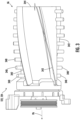
- the combing protrusions 150 may include a plurality of spaced teeth/ribs 152 with angled edges 153 (see, e.g., FIG. 6 ) extending into contact with a surface of the brush roll 122 and/or the leading roller 124.
- the spaced ribs 152 extend from a back support 151 with base portions 154 located therebetween to reinforce the spaced ribs 152.
- the illustrated embodiment shows the combing unit 149 with teeth 152 extending from a single back support 151, the combing unit 149 may also include multiple back supports 151, each with one or more include teeth 152.
- the angled edges 153 of the spaced ribs 152 may be arranged at an angle A (see FIGS.
- This example structure of the combing protrusions 150 may allow for increased strength and reduced frictional loses since less points may contact the brush roll 122 and/or the leading roller 124.
- Other shapes and configurations for the combing protrusions 150 are also within the scope of the present disclosure.
- the combing teeth 152 have angled leading edges 153 that are not aligned with a rotation center of the agitator(s) 122, 124.
- the angled leading edges 153 are the edges that an incoming portion of the rotating agitator(s) 122, 124 hits first and are directed toward or into a direction of rotation of the agitator(s) 122, 124. More specifically, the leading edge 153 of a combing tooth 152 forms an acute angle ⁇ relative to a line extending from an intersection point where the leading edge 153 intersects with an outer surface of the agitator(s) 122, 124 to the rotation center.
- the angle is in a range of 5° to 50° and more specifically in a range of 20° to 30° and even more specifically about 24° to 25°.
- the combing teeth 152 are positioned as close as possible to the bottom contact point of the agitator(s) 122, 124 but high enough to prevent being caught on a surface being cleaned (e.g., a carpet).
- the combing teeth 152 may be positioned just above the lowest structure on the housing 110 of the cleaning apparatus 100. Positioning the combing teeth 152 closer to the bottom contact point of the agitator(s) 122, 124 allows debris to be intercepted and removed as soon as possible, thereby improving debris removal.
- the combing unit 149 may have other orientations and positions relative to the agitator(s) 122, 124 (e.g., above the rotation center). In a robotic vacuum cleaner, for example, the combing unit 149 may be positioned higher to prevent the combing teeth 152 from interfering with the debris being deposited into a dust bin.
- the combing teeth 152 may extend into the agitator(s) 122, 124 to a depth in a range of 0% to 50% of the cleaning roller radius for a soft roller and 0% to 30% of the cleaning roller radius for a tufted brush roll.
- the cleaning roller 124 is a soft roller (e.g., nylon bristles with a diameter less than or equal to 0.15 mm and a length greater than 3 mm) and the combing teeth 152 extend into the soft cleaning roller 124 in a range of 15% to 35%.
- one or more of the combing teeth 152 may be configured to contact the bristles 340 ( FIG. 3 ) or flexible strips/sidewalls 342.
- the combing teeth 152 have a triangular-shaped "tooth" profile with a wider base or root 154 (see, e.g., FIG. 6 ) having a root width W r and a tip 156 having a diameter D r .
- the base or root 154 may be wide enough to prevent the tooth 152 from bending upward when contacted by the rotating cleaning roller 124 and the tip 156 may be sharp enough to catch the debris.
- the tip 156 may be rounded with a diameter in the range of less than 3 mm and more specifically in the range of 1 to 2 mm and even more specifically about 1.6 mm.
- the root width W r may be in a range of 5 to 6 mm.
- combing teeth 152 have a curved profile with curved leading edges 153 forming a concave curve.
- a line extending from the curved leading edge 153 at the tip 156 forms an angle ⁇ with the line extending from the intersection point to the rotation center RA1/RA2.
- the combing teeth 152 with curved edges may be positioned and spaced similar to the teeth 152 with straight leading edges 153 as described and shown herein.
- the combing unit 149 may include combing teeth 152 spaced 4 to 16 teeth per inch and more specifically 7 to 9 teeth per inch.
- the combing teeth 152 may be made of plastic or metal and may have a thickness that provides a desired rigidity to prevent bending when engaged with the agitator(s) 122, 124. In some embodiments, the combing teeth 152 may have a thickness in a range of 0.5 to 2 mm depending upon the material. In one example, the combing teeth 152 are made of plastic and have a thickness of 0.8 mm, a spacing S of about 2.4 mm, and a center-to-center spacing S c of about 3.3 mm.
- a combing unit 149 may also include teeth 152 with different spacings including, for example, groups of equally spaced teeth.
- the combing unit 149 may include a section at the center of the agitator(s) 122, 124 with no teeth and groups of combing teeth 152 proximate ends of the agitator(s) 122, 124 where the hair and similar debris migrates during rotation.
- the combing unit 149 is shown with teeth 152 having the same shape or tooth profile and dimensions, the combing unit 149 may include teeth of different shapes, profiles dimensions and configurations at different locations along the combing unit 149.
- the combing unit 149 may extend along a substantial portion of a length of the agitator(s) 122, 124 (i.e., more than half) such that the combing teeth 152 remove debris from a substantial portion of the cleaning surface of the agitator(s) 122, 124.
- the combing teeth 152 may engage the cleaning surface of the agitator(s) 122, 124 along, for example, greater than 90% of a length of one or more of the cleaning surface(s) of the agitator(s) 122, 124.
- the combing unit 149 works particularly well with agitator(s) 122, 124 that are designed to move hair and other similar debris away from a center of the agitator(s) 122, 124.
- the combing unit 149 may be mounted to any portion of the surface cleaning head 100.
- the combing unit 149 may be mounted within a chamber 126, 128 containing either the brush roll 122 and/or the leading roller 124.
- the combing unit 149 may be mounted, coupled, and/or otherwise secured to a portion of the surface cleaning head 100 (e.g., a portion of the housing 110) using one or more isolators 170.
- the isolators 170 may comprise an elastomeric material configured to absorb at least some of the energy (e.g., acoustic and/or vibrational energy) transmitted by the rotating roller as it rotates past and contacts the plurality of teeth of the debriding rib.
- the isolator 170 may convert the energy (e.g., acoustic and/or vibrational energy) from the combing unit 149 into heat, thereby reducing the transfer of acoustic and/or vibrational energy to the cleaning apparatus 100 (e.g., but not limited to, the nozzle housing 110).
- the isolators 170 therefore significantly reduce the noise and/or vibration due to the interaction of either the brush roll 122 and/or the leading roller 124 against the combing unit 149, which in turn improves the user experience.
- the isolator 170 is disposed between the back support 151 of the combing unit 149 and the housing 110 (e.g. nozzle).
- the isolator 170 may be disposed between the back support 151 of the combing unit 149 and an interior surface 172 of the chamber 126, 128 containing either the brush roll 122 and/or the leading roller 124.
- the isolator 170 may be located between the combing unit 149 and an exterior surface 174, and between the isolator 170 and any surface between the interior and exterior surfaces 172, 174.
- the isolator 170 may therefore be configured to contact at least a portion of the combing unit 149 and the housing 110.
- FIG. 9 a perspective view of one embodiment of the combing unit 149 and an isolator 170 is generally shown.
- a single isolator 170 is shown extending substantially continuously with (e.g., coextensive with) the combing unit 149 (e.g., the back support 151), though it should be appreciated that one or more isolators 170 may be adjacent to each other along the longitudinal length L of the combining unit 149 (e.g., the back support 151).
- two or more isolators 170 may be run parallel to each other along a common portion of the combing unit 149 in a side-by-side arrangement and/or two or more isolators 170 may run sequentially to each other when moving along the longitudinal axis L of the combing unit 149.
- two or more isolators 170 may be stacked upon each other in a direction substantially transverse the longitudinal axis L.
- the phrase "substantially coextensive with” is intended to mean that the isolator 170 is in contact with at least 80% of the surface of the combining unit 149 (e.g., the back support 151) that is immediately adjacent to (e.g., between) the combining unit 149 and the mounting surface with the housing 110.
- the isolator 170 may contact at least 90% of the surface of the combining unit 149 and/or contact at least 95% of the surface of the combining unit 149.
- the isolator(s) 170 do not have to be coextensive with the combing unit 149 (e.g., the back support 151).
- the isolator(s) 170 may be disposed between the combing unit 149 and the housing 110 along only a portion of the combing unit 149.
- the isolator 170 may include a rubber material.
- the isolator 170 may include a foam material such as, but not limited to, a closed and/or open cell foam and/or sponge.
- the material may include Ethylene Propylene Diene Monomer (EPDM) closed cell sponge rubber.
- EPDM Ethylene Propylene Diene Monomer
- the isolator 170 may have a thickness in the range of 1/16" to 1".
- the isolator 170 may optionally provide weather-proofing capabilities.
- one or more surfaces of the isolator 170 may include an adhesive layer 177.
- the adhesive layer 177 may disposed on an inner surface 178 of the isolator 170 to secure the isolator 170 to the combing unit 149, for example, to the backing support 151, to facilitate assembly of the combing unit 149 to the housing 110.
- the adhesive layer 177 may disposed on an outer surface 179 of the isolator 170 to secure the isolator 170 to the housing 110.
- the isolator 170 may be configured to primarily reduce noise, not necessarily vibrations.
- the isolator 170 may be used to dampen sound caused by the agitator(s) 122, 124 contacting the combing unit 149 and being transmitted to the housing 110.
- Using the isolator 170 may reduce the noise factor by "deadening" the resonating qualities of the sound waves. For example, waves and valleys in the foam can trap the sound waves and interrupt them.
- the isolator 170 may also reduce vibration from being transmitted from the combing unit 149 to the housing 110.
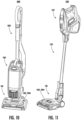
- FIGS. 10 and 11 illustrate examples of two different types of vacuum cleaners 1000, 1100 that may include a surface cleaning head 100 and a combing unit (not shown) consistent with the embodiments described herein.
- the vacuum cleaner 1000 may include an upright vacuum cleaner with a removable canister 1001 coupled to a wand 1002, such as the type described in U.S. Patent Application Pub. No. 2015/0351596 .
- the vacuum cleaner 1100 may include a stick type vacuum cleaner with a removable handheld vacuum 1101 coupled at one end of a wand 1102, such as the type described in U.S. Patent Application Pub. No. 2015/0135474 .
- FIG. 12 illustrates a robotic vacuum cleaner 1200 that includes a surface cleaning head 100 having a housing 110 and one or more agitators 122/124 with a combing unit (not shown) as disclosed herein.
- the robotic vacuum cleaner 1200 may also include one or more wheels 1203 for moving about a surface to be cleaned.
- An example of the combing unit used in a robotic vacuum cleaner is disclosed in greater detail in U.S. Provisional Application No. 62/469,853, filed March 10, 2017 .
- combing units are generally effective at preventing and/or reducing debris buildup on the agitator, the contact between the combing teeth and the agitator may cause noise and/or wear to the combing teeth or agitator as the agitator rotates.
- One or more aspects of the present disclosure may feature systems and methods for removing debris from a cleaning roller using a combing unit which can be selected between an active mode and an inactive mode.
- the combing unit may be mounted within the suction conduit (e.g., an agitation chamber) such that one or more of the combing teeth are configured to contact against at least a portion of one or more agitators (e.g., a brush roll, a leading roller, and/or the like) as the agitator rotates within the suction conduit.
- agitators e.g., a brush roll, a leading roller, and/or the like
- Contact between the combing teeth and the agitator may generally prevent and/or reduce debris (e.g., but not limited to, hair or the like) from becoming wrapped around the agitator.
- the agitator may rotate within the suction conduit without contacting a combining unit.
- the combining unit may be user selectable between the active mode and inactive mode (i.e., the user may select between the active mode and the inactive mode).
- the combining unit may be automatically toggled between the active mode and inactive mode.
- the combining unit may be automatically toggled between the active mode and inactive mode in response to one or more predefined events such as, but not limited to, upon powering up and/or powering down the agitator and/or surface cleaning head, after a predetermined amount of time, or the like.
- the surface cleaning head 100 may form part of any cleaning apparatus including, without limitation, an "all in the head" type vacuum, upright vacuum cleaners, canister vacuum cleaners, stick vacuum cleaners, robotic vacuum cleaners and central vacuum systems, and may be used in sweepers (e.g., low or no suction).
- the surface cleaning head 100 includes a housing 110 including a suction conduit 128 having an opening 127 on the underside 120 of the housing 110.
- the suction conduit 128 is fluidly coupled to a dirty air inlet 129, which leads to a suction motor (not shown) either in the surface cleaning head 100 or another location in the vacuum.
- the illustrated surface cleaning head 100 includes a single agitator 122, 124 at least partially disposed within the suction conduit 128, it should be appreciated that the surface cleaning head 100 may include multiple rotating agitators (for example, a brush roll 122 and a leading roller 124) disposed in one or more agitation chambers.
- the surface cleaning head 100 may also include one or more wheels 130 and/or additional features not shown, but described herein.
- the surface cleaning head 100 may also include one or more combing units/debriders 149 each having a series of combing protrusions (also referred to as debriding protrusions) 150 configured to contact one or more of the agitators (e.g., brush roll 122 and/or the leading roller 124).
- the combing unit 149 as shown in greater detail in FIGS. 4-5 .
- the combing protrusions 150 may be configured to remove debris (such as, but not limited to, hair, string, and the like) that may be wrapped around and/or entrapped/entrained in/on the agitator 122, 124 as the surface cleaning head 100 is being used.
- the combing protrusions 150 may include a plurality of spaced teeth/ribs 152 with angled edges 153 (see, e.g., FIG. 6 ).
- the combing unit 149 may be coupled to the housing 110 such that the combing protrusions 150 contact a surface of the agitator 122, 124 (such as, but not limited to, contact with the bristles 340 or flexible strips/sidewalls 342 as generally illustrated in FIG. 8 ).
- the combing unit 149 may be coupled to any portion of the housing 110.
- the combing unit 149 may be coupled to a removable panel 1302 such that combing unit 149 contacts the agitator 122, 124 as the agitator 122, 124 rotates.
- the removable panel 1302 may be referred to an active mode panel 1302.
- the active mode panel 1302 may be secured to any side of the housing 110 such as, but not limited to, the upper side/surface 118.
- at least a portion of the active mode panel 1302 may be formed from a transparent and/or semi-transparent material. In this manner, the user may see the combing unit 149 engaging with the agitator 122, 124 as the agitator 122, 124 rotates within the suction conduit 128 during normal use.
- the active mode panel 1302 may be removed from the housing 110 by a user as indicated by arrow 1402 in FIG. 14 and replaced with a removable inactive mode panel 1502 as generally illustrated in FIG. 15 .
- the inactive mode panel 1502 may include a removable panel configured to be removably secured to the housing 110 which does not have a combing unit 149.
- the inactive mode panel 1502, FIG. 16 may include a removable panel configured to be removably secured to the housing 110 which includes a combing unit 149 configured to not contact the agitator 122, 124 as the agitator 122, 124 rotates.
- the combing unit 149 of the active mode panel 1302 may be configured move from an active position (as generally illustrated in FIG. 13 ) to an inactive position in which the combing unit 149 is configured to not contact the agitator 122, 124 (as generally illustrated in FIG. 14 ) .
- the inactive mode panel 1502 may be the same as the active mode panel 1202 with the combing unit 149 in a different position.
- the inactive mode panel 1502 may be a separate and distinct panel from the active mode panel 1302. In such an embodiment, the active mode panel 1302 of FIG.
- the active mode and inactive mode panels 1302, 1502 may be secured to the housing 110 in any manner known to those of ordinary skill in the art.
- the panels 1302, 1502 may be secured to the housing 110 using a connection mechanism that does not require the use of any tools.
- tool-less connection mechanisms includes depressible tabs, latches, detents, buttons, or the like.
- FIG. 17 one example of a surface cleaning head 100 including an active mode panel 1302 having a combing unit 149 in the active position is generally illustrated.
- the plurality of teeth 150 of the combing unit 149 extend from the active mode panel 1302 and contact the agitator 122, 124.
- the plurality of teeth 150 may contact the bristles 340 and/or the flexible sidewall 342 as described herein.
- a portion 1702 of the active mode panel 1302 may be formed from a transparent and/or semi-transparent material such that the interaction between the combing unit 149 and the agitator 122, 124 may be seen by the user while using the vacuum in normal use.
- an inactive mode panel 1502 having a combing unit 149 in the inactive position is generally illustrated.
- the teeth 150 of the combing unit 149 have been configured (e.g., positioned and/or modified) such that the agitator 122, 124 does not contact the combining unit 149 when the inactive mode panel 1502 is secured to the housing 110 and the agitator 122, 124 rotates within the suction conduit 128.
- the inactive mode panel 1502 may optionally include indicia to identify that the inactive mode panel 1502 for use in the inactive mode.
- the inactive mode panel 1502 may include a different color or the like to differentiate it from the active mode panel 1302.
- FIG. 19 generally illustrates another example of an inactive mode panel 1502.
- the inactive mode panel 1502 does not include a combing unit 149.
- the inactive mode panel 1502 may include a portion 1902 formed from a transparent and/or semi-transparent material such that the rotation of the agitator 122, 124 may be seen by the user while using the vacuum in normal use.
- the transparent and/or semi-transparent portion 1902 of the inactive mode panel 1502 may be the same size and/or shape as the transparent and/or semi-transparent portion 1702 of the active mode panel 1302.
- the surface cleaning head 100 includes a housing 110 including a suction conduit 128 having an opening 127 on the underside 120 of the housing 110.
- the suction conduit 128 is fluidly coupled to a dirty air inlet 129, which leads to a suction motor (not shown) either in the surface cleaning head 100 or another location in the vacuum.
- the illustrated surface cleaning head 100 includes a single agitator 122, 124 at least partially disposed within the suction conduit 128, it should be appreciated that the surface cleaning head 100 may include multiple rotating agitators (for example, a brush roll 122 and a leading roller 124) disposed in one or more agitation chambers.
- the surface cleaning head 100 may also include one or more wheels 130 and/or additional features not shown, but described herein.
- the surface cleaning head 100 may also include one or more combing units/debriders 149 each having a series of combing protrusions (also referred to as debriding protrusions) 150 configured to contact one or more of the agitators (e.g., brush roll 122 and/or the leading roller 124).
- the combing unit 149 as shown in greater detail in FIGS. 4-5 .
- the combing protrusions 150 may be configured to remove debris (such as, but not limited to, hair, string, and the like) that may be wrapped around and/or entrapped/entrained in/on the agitator 122, 124 as the surface cleaning head 100 is being used.
- the combing unit 149 may be secured to any part of the surface cleaning head 100.
- the combing unit 149 may be secured to the housing 110 and/or to a removable panel 2004 such that a portion of the combing unit 149 contacts an agitator 122, 124 during the active mode as the agitator 122, 124 rotates within the agitation chamber/suction conduit 128.
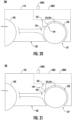
- the surface cleaning head 100 also includes one or more switch 2002 configured to toggle the combing unit 149 between an active mode (as generally illustrated in FIG. 20 ) and an inactive mode (as generally illustrated in FIG. 21 ).
- the switch 2002 may be secured to any part of the surface cleaning head 100.
- the switch 2002 may be secured to the housing 110 and/or to the removable panel 2004.
- the switch 2002 may be configured to cause the combing unit 149 to remain in the selected mode (e.g., either the active mode or inactive mode) until a switch activation force is applied to select the other mode. In this manner, the combing unit 149 may be locked in the active mode and inactive mode, and remain in the selected mode.
- the selected mode e.g., either the active mode or inactive mode
- the switch 2002 may be configured to cause the combing unit 149 to default in one mode unless the switch 2002 an activation force is applied to the switch 2002.
- the switch 2002 may be configured to cause the combing unit 149 to remain in the inactive mode (i.e., the default setting).
- the combing unit 149 may be moved from the inactive mode to the active mode.
- the switch activation force e.g., a user and/or actuator stops urging the switch 2002
- the switch 2002 may be configured to automatically revert back to the inactive mode.
- the automatic return to the default setting may be provided by, for example, a return spring or the like.
- the default setting may alternatively be the active setting.
- activation of the switch 2002 is configured to cause the combing unit 149 (and in particular the teeth 150) to move linearly between the active position shown in FIG. 22 and the inactive position as shown in FIG. 23 .
- the switch 2002 may be depressed downwardly from the upper surface 118 towards the underside 120 of the housing 110 as generally illustrated by arrow 2304 in FIG. 23 .
- the switch 2002 may be moved generally left/right (e.g., generally towards the left and right sides 116a, 116b) and/or front/back (e.g., generally towards the front side 112 and back side 114).
- activation of the switch 2002 is configured to cause the combing unit 149 (and in particular the teeth 150) to move linearly away from the agitator 122, 124.
- activation of the switch 2002 is configured to cause the combing unit 149 to move towards the upper surface 118 of the housing 110. It should be appreciated, however, that activation of the switch 2002 may cause the combing unit 149 to move linearly away from the agitator 122, 124 in any direction.
- activation of the switch 2002 may be configured to cause the combing unit 149 to move linearly in any direction from the inactive position to the active position.
- activation of the switch 2002 is configured to cause the combing unit 149 (and in particular the teeth 150) to rotate about a pivot axis 2402 between the active position shown in FIG. 24 and the inactive position as shown in FIG. 26 .
- the switch 2002 may be depressed downwardly from the upper surface 118 towards the underside 120 of the housing 110 as generally illustrated by arrow 2504 in FIG. 25 .
- the switch 2002 may be moved generally left/right (e.g., generally towards the left and right sides 116a, 116b) and/or front/back (e.g., generally towards the front side 112 and back side 114).
- FIGS. 26-27 one example of a switch 2002 configured to cause the combing unit 149 (and in particular the teeth 150) to rotate about a pivot axis 2402 between the active position and the inactive position is generally illustrated.
- the switch 2002 and the combing unit 149 are both part of a removable panel 2004 which is configured to be removable coupled to the housing 110 (not shown) as described herein. As such, removal of the panel 2004 from the housing 110 simultaneously removes both the switch 2002 as well as the combing unit 149. It should be appreciated, however, that the switch 2002 and/or the combing unit 149 may be coupled to any part of the surface cleaning head 100.
- the switch 2002 may include an actuation tab 2802 configured to engage a cam 2804.
- the actuation tab 2802 may be configured to move left/right (e.g., between the left and right sides 116a, 116b of the housing 110) when coupled to the housing 110 as generally illustrated in FIGS 29A, 29B .
- the actuation tab 2802 may slide within a groove or slot 2806 formed in the housing 110 (e.g., but not limited to, in the removable panel 2004).
- the actuation tab 2802 is configured to be coupled to the cam 2804 such that linear movement of the actuation tab 2802 (e.g., linear left/right movement) causes the cam 2804 to rotate about the pivot axis 2402.
- the cam 2804 may be coupled to the combing unit 149 such that rotation of the cam 2804 about the pivot axis 2402 also causes rotation of the combing unit 149 about the pivot axis 2402.
- the cam 2804 may therefore translate the linear movement of the actuation tab 2802 into rotational movement of the combing unit 149.
- the actuation tab 2802 may include a body 3002 configured to be at least partially received in the slot 2806 in the housing 110.
- the actuation tab 2802 may include one or more protrusions, ribs, slots, or the like 3004.
- the protrusion 3004 may extend from/within an upper surface 3006 of the body 3002 (i.e., a surface that is exposed to the user in normal use) and may be configured to allow a user to move the actuation tab 2802 relative to the housing 110.
- the actuation tab 2802 may also include one or more posts or fingers 3008.
- the fingers 3008 may extend from a lower surface 3010 of the body 3002 and may be configured to engage with the cam 2804 such that movement of the actuation tab 2802 causes rotation of cam 2804.
- the cam 2804 may be coupled to the combing unit 149 (e.g., coupled to the back support 151). Alternatively, the cam 2804 may be formed as a single unit with at least a portion of the combing unit 149 (e.g., the back support 151).
- the cam 2804 may include body 3102 including one or more camming surface 3104.
- the cam 2804 may include a barrel cam including a slot 3106 configured to receive at least a portion of the finger 3008 of the actuation tab 2802.
- the slot 3106 may include a generally helical slot, and may include camming surfaces 3104 configured to engage with the finger 3008 of the actuation tab 2802 to cause rotation about the pivot axis 2402.
- the degree of rotation about the pivot axis 2402 may depending on the intended application.
- movement of the actuation tab 2802 within the slot 3106 may cause the cam 2804 and combing unit 149 to rotate at least 10 degrees about the pivot axis 2402.
- the cam 2804 and combing unit 149 may rotate at least 20 degrees, at least 25 degrees, at least 30 degrees, at least 45 degrees, at least 60 degrees, and/or at least 90 degrees about the pivot axis 2402, including all values and ranges therein.
- the actuation tab 2802 may travel within the slot 2806 up to 60 mm.
- the actuation tab 2802 may travel within the slot 2806 up to 50 mm, up to 40 mm, up to 30 mm, and/or up to 20 mm, including all values and ranges therein.
- the switch 2002 may optionally include one or more biasing devices 2702.
- the biasing devices 2702 may urge the switch 2002 to a default position/mode as described herein.
- the biasing device 2702 may include one or more springs configured to urge the switch 2002 towards the inactive mode or towards the active mode.
- a user would apply a switch activation force to move the switch 2002 from the default position/mode to the opposite position/mode.
- the switch activation force may therefore be in excess of the switch activation force.
- the switch 2002 may automatically revert back to the default position/mode.
- the biasing device 2702 may be selected to ensure that a sufficient force is applied to cause the combing unit 149 to remain in contact with the agitator 122, 124 during rotation of the agitator 122, 124 such that the combing unit 149 removes debris from the agitator 122, 124 while the agitator 122, 124 rotates.
- the switch 2002 may be configured to remain in one or more of the selected positions/modes until an activation force is applied.
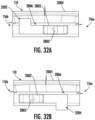
- the slot 2806 may be configured with one or more retaining regions. Non-limiting examples of retaining regions 3202, 3204 are generally illustrated in FIGS. 32A and 32B .
- the slot 2806 may include an active mode retaining region 3202 disposed proximate a first end of the slot 2806 and/or an inactive mode retaining region 3204 disposed proximate a second, opposite end of the slot 2806.
- the slot 2806 may be configured to allow the actuation tab 2802 to be moved into one or more of the retaining regions 3202, 3204 and retained therein.
- the size and shape of the retaining regions 3202, 3204 may be selected to retain the actuation tab 2802.
- a retaining device such as, but not limited to, a latch, catch, clip, or the like
- the actuation tab 2802 may remain in the selected mode until the actuation tab 2802 is either manually moved from the retaining region 3202, 3204 and/or the retaining device is disconnected.
- the switch 2002 may be coupled to the housing 110 rather than to a removable panel 3302.
- the switch 2002 and the combing unit 149 may be permanently coupled to the housing 110.
- the switch 2002 may be coupled to the combing unit 149 using one or more linkages and/or gears such that activation of the switch 2002 causes the combing unit 149 to move between the active position and inactive position.
- the surface cleaning head 100 may include one or more actuators 3402 as generally illustrated in FIG. 34 .
- the actuator 3402 may be configured to cause the switch 2002 to move between the active mode and inactive mode, for example, based on one or more conditions.
- the actuator 3402 is configured to alternative between the modes in response to a sensor 3404.
- the actuator 3402 may alternate between the modes periodically (e.g., every 30 seconds), upon the occurrence of one or more predefined events (e.g., upon powering on and/or off the vacuum cleaner).
- the sensor 3404 may be configured to sense the amount of debris on the agitator 122, 124, and cause the actuator 3402 to move the switch 2002 from the inactive mode to the active mode upon exceeding a threshold value.
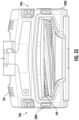
- the sensor 3404 may include a load sensor, optical sensor, or the like.
Landscapes
- Engineering & Computer Science (AREA)
- Mechanical Engineering (AREA)
- Nozzles For Electric Vacuum Cleaners (AREA)
Description
- The present disclosure relates to cleaners with cleaning rollers/agitators and more particularly, to a cleaning apparatus, such as a surface cleaning head for a vacuum cleaner, with a combing unit for removing debris from a cleaning roller/agitator which can be selected between an active mode and an inactive mode.
- Vacuum cleaners generally include a suction conduit with an opening on the underside of a surface cleaning head for drawing air (and debris) into and through the surface cleaning head. One of the challenges with vacuum cleaner design is to control engagement of the suction conduit with a surface being cleaned to provide the desired amount of suction. If the suction conduit is spaced too far from a surface, the suction may be less because the air is flowing into the suction conduit through a greater surface area. If the suction conduit is directly engaged with the surface and thus sealed on all sides, air will stop flowing into the suction conduit and the suction motor may be damaged as a result.
- Vacuum cleaners also generally use agitation to loosen debris and facilitate capturing the debris in the flow of air into the suction conduit. Agitators are often used in the suction conduit of a surface cleaning head proximate a dirty air inlet to cause the agitated debris to flow into the dirty air inlet. If the agitator in the suction conduit is unable to loosen the debris or if the debris is too small, the suction conduit may pass over the debris without removing the debris from the surface. In other cases, the surface cleaning head may push larger debris forward without ever allowing the debris to be captured in the flow into the suction conduit (sometimes referred to as snowplowing).
- One example of an agitator is a cleaning roller such as a brush roll. A cleaning roller may be located within a suction conduit and/or may be located at a leading side of a suction conduit (e.g., a leading roller). One challenge with a leading roller in particular is the debris (e.g., hair) that becomes entangled around the roller. Projections may be used to engage the roller to facilitate removal of debris, but existing structures are often not effective and/or interfere with the operation of the surface cleaning head.
- One solution to generally reduce and/or prevent debris from becoming entangled around the roller is to include a debriding rib/combing unit. The debriding rib/combing unit may include a plurality of teeth that contact and cut the debris on the roller as the roller rotates past the debriding rib/combing unit. In some embodiments, a portion of the roller may also contact the plurality of teeth of the debriding rib/combing unit. While the debriding rib/combing unit is effective at generally reducing and/or preventing debris from becoming entangled around the roller, the contact between the roller and the plurality of teeth of the debriding rib/combing unit may cause unwanted noise and/or vibration As such, there exists a need for device that can generally reduce and/or prevent debris from becoming entangled around the roller while also minimizing and/or eliminating undesired noise and/or vibration.
WO2016/030756A1 describes a vacuum cleaner head having a housing, supports extending downward from the housing to a support point, a suction opening, an agitator chamber above and in fluid communication with the suction opening, an agitator with a spindle rotatably mounted to the housing and one or more agitating devices projecting from the spindle, a cleaning member movably mounted to the housing to move to a position where it engages the agitator to remove debris from the agitator during rotation of the agitator, and a pedal connected to the housing and movable to a position to place the cleaning member in the cleaning position. The pedal has an activation surface configured to receive an activation force from an operator, and the activation surface is configured such that application of the activation force on the pedal generates a moment force to bias the agitator away from the downward direction.
US2960714A describes a combination vacuum cleaner and carpet sweeper including a casing having symmetrically disposed dirt receiving chambers, a revolvable brush mounted in said casing so that its tufts protrude therefrom for carpet sweeping purposes, retractable pins carried by said casing and extending into said chambers between tufts of said brush to rid the latter of lint and threads during operation of the brush, spring means for biasing said pins to such extension, cam means driven by said brush for periodically retracting said pins and stripping lint and thread therefrom to fall into said chambers and means for removing collected dirt, lint and thread from said chambers.EP2543301A1 describes an upright cleaner configured to remove dust from a drum brush. The upright cleaner includes a case having a suction port, a drum brush rotatably provided in the case to sweep and guide foreign matter to the suction port, a dust removal unit provided in the case so that the dust removal unit is moved between a first position where one side of the dust removal unit contacts the drum brush and a second position where the side of the dust removal unit is separated from the drum brush, and a lever connected to the dust removal unit to actuate the dust removal unit. - These and other features and advantages will be better understood by reading the following detailed description, taken together with the drawings wherein:
-
FIG. 1 is a perspective view of a surface cleaning head including dual agitators, combing protrusions, and an isolator, consistent with an embodiment of the present disclosure. -
FIG. 2 is a side cross-sectional view of the surface cleaning head shown inFIG. 1 showing a flow path through a suction conduit. -
FIG. 3 is a side view of a portion of an agitator consistent with one or more aspects of the present disclosure including bristles and flexible sidewalls. -
FIG. 4 is a front perspective view of the front region of the surface cleaning head ofFIG. 1 without the leading roller and illustrating the combing unit. -
FIG. 5 is an enlarged perspective view of one embodiment of a combing unit. -
FIG. 6 is an enlarged view of a portion of the combing unit ofFIG. 5 . -
FIG. 7 is an enlarged view of another portion of the combing unit ofFIG. 5 . -
FIG. 8 is a cross-sectional view of one embodiment showing the combing unit coupled to the housing of a surface cleaning head with an isolator. -
FIG. 9 is a front view one embodiment of a combing unit and an isolator. -
FIG. 10 is a perspective front view of an upright vacuum cleaner including the combing unit and isolator. -
FIG. 11 is a perspective front view of a stick type vacuum cleaner including the combing unit and isolator. -
FIG. 12 is a perspective bottom view of a robot vacuum cleaner including the combing unit and isolator. -
FIG. 13 is one example of a surface cleaning head including a combining unit configured to be toggled between an active mode and an inactive mode. -
FIG. 14 is one example of a surface cleaning head with a removable panel. -
FIG. 15 is one example of a surface cleaning head with a removable panel without a combining unit in an inactive mode. -
FIG. 16 is one example of a surface cleaning head with a removable panel having a combining unit in an inactive mode. -
FIG. 17 is one example of a surface cleaning head with a removable panel having a combining unit in an active mode. -
FIG. 18 is one example of a removable panel surface having a combing unit in the inactive mode. -
FIG. 19 is one example of a removable panel surface without a combing unit in the inactive mode. -
FIG. 20 is one example of a surface cleaning head including a switch configured to toggle a combining unit between an active mode and an inactive mode. -
FIG. 21 is one example of a surface cleaning head including a switch configured to position a combining unit in an inactive mode. -
FIG. 22 is one example of a surface cleaning head including a combining unit in an active mode and a switch configured to move the combing unit linearly. -
FIG. 23 is one example of a surface cleaning head ofFIG. 22 in an inactive mode. -
FIG. 24 is one example of a surface cleaning head including a combining unit in an active mode and a switch configured to pivot the combing unit. -
FIG. 25 is one example of a surface cleaning head ofFIG. 24 in an inactive mode. -
FIG. 26 is one example of a removable panel including a combining unit and a switch configured to move the combing unit linearly. -
FIG. 27 is a transparent view ofFIG. 26 . -
FIG. 28 is a cross-sectional view ofFIG. 26 taken along lines A-A. -
FIGS. 29A and 29B are close-up views of the switch and slot ofFIG. 26 . -
FIG. 30 is a perspective view of one example of a switch body of a switch. -
FIG. 21 is a perspective view of one example of a cam of a switch coupled to a combing unit. -
FIGS. 32A and 32B are close-up views another example of a slot and switch. -
FIG. 33 is one example of a surface cleaning head including a combining unit in a switch coupled to the housing. -
FIG. 34 is one example of a surface cleaning head including a combining unit, a switch, and an actuator configured to toggle the combing unit between an active mode and an inactive mode. - A cleaning apparatus, consistent with at least one aspect of the present disclosure, includes a housing, at least one agitator configured to be rotatably coupled to the housing, a combing unit comprising a plurality of spaced teeth configured to contact the agitator for preventing build up and removing debris, and an switch configured to cause the combing unit to move between an active mode in which the plurality of spaced teeth are configured to contact the agitator for preventing build up and removing debris, and an inactive mode in which the plurality of spaced teeth are configured to not contact the agitator. Alternatively (or in addition), a cleaning apparatus, consistent with at least one aspect of the present disclosure, includes a housing, at least one agitator configured to be rotatably coupled to the housing, and a first panel configured to be removably coupled to the housing. The first panel includes a combing unit comprising a plurality of spaced teeth configured to contact the agitator when secured to the housing for preventing build up and removing debris. The surface cleaning head may also include at least one of a second panel configured to be removably coupled to the housing which does not include a combing unit, a third panel configured to be removably coupled to the housing which includes a combing unit comprising a plurality of spaced teeth which do not contact the agitator when secured to the housing, or the first panel in which the combing unit is configured to move between a first position in which the plurality of spaced teeth are configured to contact the agitator, and a second position in which the plurality of spaced teeth do not contact the agitator.
- The combing unit (also referred to as a debriding unit or rib) includes a plurality of spaced protrusions or teeth extending into a cleaning roller (e.g., agitator) for preventing build up and removing debris (such as hair, string, and the like). The protrusions may extend along a substantial portion of the cleaning roller and extend partially into the cleaning roller to intercept the debris as it passes around the roller. The protrusions may have angled leading edges that are not aligned with a rotation center of the cleaning roller and are directed into or against a direction of rotation of the cleaning roller. The combing unit and protrusions may have a shape and configuration designed to facilitate debris removal from the cleaning roller with minimal impact on the operation of the cleaning apparatus. The cleaning apparatus may include a surface cleaning head of an upright vacuum cleaner or sweeper or a robotic vacuum cleaner.
- The combing unit may be mounted, coupled, and/or otherwise secured to a portion of the clearing apparatus using one or more isolators. The isolators may comprise an elastomeric material configured to absorb at least some of the energy transmitted by the rotating roller as it rotates past and contacts the plurality of teeth of the debriding rib and convert the energy (e.g., vibrational energy). For example, the isolator may absorb at least some of the energy transmitted by the rotating roller into heat, thereby reducing the acoustical energy and/or transfer of vibrational energy to the cleaning apparatus (e.g., but not limited to, the nozzle casing). The isolators therefore significantly reduce the noise and/or vibration due to the interaction of the roller against the combing unit, which in turn improves the user experience.
- As used herein, the phrase "surface cleaning head" refers to a device configured to contact a surface for cleaning the surface by use of suction air flow, agitation, or a combination thereof. A surface cleaning head consistent with one or more aspects of the present disclosure may be used in different types of cleaning apparatuses (e.g., vacuum cleaners) including, without limitation, an "all in the head" type vacuums, upright vacuum cleaners, canister vacuum cleaners, stick vacuum cleaners, robotic vacuum cleaners and central vacuum systems, and may be used in sweepers (e.g., low or no suction), for example, as generally illustrated in
FIGS. 10-11 , as well as robotic vacuum cleaners, for example, as generally illustrated inFIG. 12 . An example of a surface cleaning head used in a robotic vacuum cleaner is disclosed in greater detail inU.S. Provisional Application No. 62/469,853, filed March 10, 2017 - A surface cleaning head may be pivotably or steeringly coupled by a swivel connection to a wand for controlling the surface cleaning head and may include motorized attachments as well as fixed surface cleaning heads. A surface cleaning head may also be operable without a wand or handle. As used herein, "seal" or "sealing" refers to preventing a substantial amount of air from passing through to the suction conduit but does not require an air tight seal. As used herein, "agitator" refers to any element, member or structure capable of agitating a surface to facilitate movement of debris into a suction air flow in a surface cleaning head. As used herein, "soft" and "softer" refer to the characteristics of a cleaning element being more compliant or pliable than another cleaning element. As used herein, the term "flow path" refers to the path taken by air as it flows into a suction conduit when drawn in by suction As used herein, the terms "above" and "below" are used relative to an orientation of the surface cleaning head on a surface to be cleaned and the terms "front" and "back" are used relative to a direction that a user pushes the surface cleaning head on a surface being cleaned (i.e., back to front). As used herein, the term "leading" refers to a position in front of at least another component but does not necessarily mean in front of all other components.
- Referring to
FIGS. 1-2 , one embodiment of asurface cleaning head 100 is generally illustrated. As noted herein, asurface cleaning head 100 may form part of a cleaning apparatus. Thesurface cleaning head 100 includes ahousing 110 with afront side 112, and aback side 114, left andright sides upper side 118, and a lower orunderside 120. Thehousing 110 defines asuction conduit 128 having anopening 127 on theunderside 120 of the housing 110 (shown inFIG. 2 ). Thesuction conduit 128 is fluidly coupled to adirty air inlet 129, which leads to a suction motor (not shown) either in thesurface cleaning head 100 or another location in the vacuum. Thesuction conduit 128 is the interior space defined by interior walls in thehousing 110, which receives and directs air drawn in by suction, and theopening 127 is where thesuction conduit 128 meets theunderside 120 of thehousing 110. - In the illustrated embodiment, the
surface cleaning head 100 includes dualrotating agitators brush roll 122 and a leadingroller 124. Thebrush roll 122 andleading roller 124 may be configured to rotate about first and second rotating axes (RA1, RA2). The rotatingbrush roll 122 is at least partially disposed within the suction conduit 128 (shown inFIG. 2 ). The leadingroller 124 is positioned in front of and spaced from thebrush roll 122 and at least substantially outside thesuction conduit 128. In some embodiments, at least an inside upper portion (e.g., upper half) of the leadingroller 124 is not exposed to the primary air flow path (e.g., arrow 40) into theopening 127 of thesuction conduit 128 while at least an inside of the bottom portion of the leadingroller 124 is exposed to the primary flow path into theopening 127 of thesuction conduit 128. - Other variations are possible where different portions of the leading
roller 124 may be exposed or not exposed to the flow path into thesuction conduit 128. In other embodiments, for example, a flow path may allow air to flow over the upper portion of the leadingroller 124. The leadingroller 124 may rotate about the second rotation axis RA2 located within a leadingroller chamber 126. The leadingroller chamber 126 may have a size and shape slightly larger than the cylindrical projection of the leadingroller 124 when the leadingroller 124 is rotating therein, for example, to form the flow path over the upper portion. WhileFIGS. 1-2 illustrate asurface cleaning head 100 having dualrotating agitators surface cleaning head 100 consistent with the present disclosure may include only a single rotating agitator or more than two agitators. - The
surface cleaning head 100 may include one ormore wheels 130 for supporting thehousing 110 on thesurface 10 to be cleaned. Thebrush roll 122 may be disposed in front of one ormore wheels 130, 132 (seeFIG. 1 ) for supporting thehousing 110 on thesurface 10 to be cleaned. For example, one or morelarger wheels 130 may be disposed along theback side 114 and/or one or more smaller middle and/orfront wheels 132 may be provided at a middle section and/or front section on theunderside 120 of thehousing 110 and/or along the left andright sides wheels surface cleaning head 100 along thesurface 10 to be cleaned, and may also allow the user to easily tilt or pivot the surface cleaning head 100 (e.g.,brush roll 122 and/or the leading roller 124) off of thesurface 10 to be cleaned. The rear wheel(s) 130 and the middle/front wheel(s) 132 may provide the primary contact with the surface being cleaned and thus primarily support thesurface cleaning head 100. When thesurface cleaning head 100 is positioned on thesurface 10 being cleaned, the leadingroller 124 may also rest on thesurface 10 being cleaned. In other embodiments, the leadingroller 124 may be positioned such that the leadingroller 124 sits just above the surface being cleaned. - The rotating
brush roll 122 may have bristles, fabric, or other cleaning elements, or any combination thereof around the outside of thebrush roll 122. Examples of brush rolls and other agitators are shown and described in greater detail inU.S. Patent No. 9,456,723 U.S. Patent Application Pub. No. 2016/0220082 . - The leading
roller 124 may include a relatively soft material (e.g., soft bristles, fabric, felt, nap or pile) arranged in a pattern (e.g., a spiral pattern) to facilitate capturing debris, as will be described in greater detail below. The leadingroller 124 may be selected to be substantially softer than that of thebrush roll 122. The softness, length, diameter, arrangement, and resiliency of the bristles and/or pile of the leadingroller 124 may be selected to form a seal with a hard surface (e.g., but not limited to, a hard wood floor, tile floor, laminate floor, or the like), whereas the bristles of thebrush roll 122 may selected to agitate carpet fibers or the like. For example, the leadingroller 124 may be at least 25% softer than thebrush roll 122, alternatively the leadingroller 124 may be at least 30% softer than thebrush roll 122, alternatively the leadingroller 124 may be at least 35% softer than thebrush roll 122, alternatively the leadingroller 124 may be at least 40% softer than thebrush roll 122, alternatively the leadingroller 124 may be at least 50% softer than thebrush roll 122, alternatively the leadingroller 124 may be at least 60% softer than thebrush roll 122. Softness may be determined, for example, based on the pliability of the bristles or pile being used. - The size and shape of the bristles and/or pile may be selected based on the intended application. For example, the leading
roller 124 may include bristles and/or pile having a length of between 5 to 15 mm (e.g., 7 to 12 mm) and may have a diameter of 0.01 to 0.04 mm (e.g., 0.01-0.03 mm). According to one embodiment, the bristles and/or pile may have a length of 9 mm and a diameter of 0.02 mm. The bristles and/or pile may have any shape. For example, the bristles and/or pile may be linear, arcuate, and/or may have a compound shape. According to one embodiment, the bristles and/or pile may have a generally U and/or Y shape. The U and/or Y shaped bristles and/or pile may increase the number of points contacting thefloor surface 10, thereby enhancing sweeping function of leadingroller 124. The bristles and/or pile may be made on any material such as, but not limited to, Nylon 6 or Nylon 6/6. - Optionally, the bristles and/or pile of leading
roller 124 may be heat treated, for example, using a post weave heat treatment. The heat treatment may increase the lifespan of the bristles and/or pile of the leadingroller 124. For example, after weaving the fibers and cutting the velvet into rolls, the velvet may be rolled up and then run through a steam rich autoclave making the fibers/bristles more resilient fibers. - The leading
roller 124 may have an outside diameter Dlr that is smaller than the outside diameter Dbr of thebrush roll 122. For example, the diameter Dlr may be greater than zero and less than or equal to 0.8Dbr, greater than zero and less than or equal to 0.7Dbr, or greater than zero and less than or equal to 0.6Dbr. According to example embodiments, the diameter Dlr may be in the range of 0.3Dbr to 0.8Dbr, in the range of 0.4Dbr to 0.8Dbr, in the range of 0.3Dbr to 0.7Dbr, or in the range of 0.4Dbr to 0.7Dbr. As an illustrative example, thebrush roll 122 may have an outside diameter of 48 mm and the leadingroller 124 may have an outside diameter of 30 mm. While the leadingroller 124 may have an outside diameter Dlr that is smaller than the outside diameter Dbr of thebrush roll 122, thebrush roll 122 may have bristles that are longer than the bristle and/or pile of the leadingroller 124. - Positioning a leading roller 124 (having a diameter Dlr that is smaller than the diameter Dbr of the brush roll 122) in front of the
brush roll 122 provides numerous benefits. For example, this arrangement decreases the height of thefront side 112 of the surface cleaning head 100 (e.g., the housing 110) from thesurface 10 to be cleaned. The decreased height of the front of thesurface cleaning head 100 provides a lower profile that allows thesurface cleaning head 100 to fit under objects (e.g., furniture and/or cabinets). Moreover, the lower height allows for the addition of one or more light sources 111 (e.g., but not limited to, LEDs), while still allowing thesurface cleaning head 100 to fit under objects. - Additionally, the smaller diameter Dlr of the leading
roller 124 allows the rotating axis of the leadingroller 124 to be placed closer to thefront side 112 of thesurface cleaning head 100. When rotating, the leadingroller 124 forms a generally cylindrical projection having a radius that is based on the overall diameter of the leadingroller 124. As the diameter of the leadingroller 124 decreases, the bottom contact surface 140 (FIG. 2 ) of the leadingroller 124 moves forward towards thefront side 112 of thesurface cleaning head 100. In addition, when thesurface cleaning head 100 contacts a vertical surface 12 (e.g., but not limited to, a wall, trim, and/or cabinet), the bottom contact surface 140 of the leadingroller 124 is also closer to thevertical surface 12, thereby enhancing the front edge cleaning of thesurface cleaning head 100 compared to a larger diameter leading roller. Moreover, the smaller diameter Dlr of the leadingroller 124 also reduces the load/drag on the motor driving the leadingroller 124, thereby enhancing the lifespan of the motor and/or allowing a smaller motor to be used to rotate both thebrush roll 122 andleading roller 124. - The rotating
brush roll 122 may be coupled to an electrical motor (either AC or DC) to cause therotating brush roll 122 to rotate about the first rotating axis. The rotatingbrush roll 122 may be coupled to the electrical motor by way of a gears and/or drive belts. The leadingroller 124 may be driven from the same drive mechanism used to drive the rotatingbrush roll 122 or a separate drive mechanism. An example of the drive mechanism is described inU.S. Patent Application Serial No. 15/331,045, filed Oct. 21, 2016 - In at least one embodiment, the
brush roll 122 and the leadingroller 124 rotate in the same direction directing debris toward thesuction conduit 128, for example, counter clockwise as shown inFIG. 2 . This arrangement may reduce the number of parts (e.g., no clutch or additional gear train may be necessary), thereby making thesurface cleaning head 100 lighter, reducing drivetrain loss (thereby allowing for smaller/less expensive motors), and less expensive to manufacture. Optionally, thebrush roll 122 and the leadingroller 124 may rotate at same speed, thereby reducing the number of parts (e.g., no additional gear train necessary) and reducing drivetrain loss (thus, smaller/less expensive motor) and making thesurface cleaning head 100 lighter and less expensive to manufacture. - As shown in
FIG. 2 , the leadingroller 124 may be positioned within thehousing 110 such that the bottom contact surface 140 is disposed closer to thesurface 10 to be cleaned compared to the bottom contact surface of thebrush roll 122. This arrangement allows the leadingroller 124 to contact a surface 10 (e.g., a hard surface) without thebrush roll 122 contacting thehard surface 10. As may be appreciated, the leadingroller 124 is intended to pick up debris from ahard surface 10 while thebrush roll 122 is intended to primarily contact a carpet surface. This arrangement is therefore beneficial since it allows the leadingroller 124 to form a seal between the front 112 of thesurface cleaning head 100 with thehard surface 10, thereby enhancing airflow and suction with thehard surface 10. Additionally, this arrangement reduces the drag/torque on the drive motor(s) since the brush roll 122 (in some embodiments) does not have to contact thehard surface 10. The reduced drag/torque may allow for a smaller, less expensive motor and/or may increase the lifespan of the motor. - One or both of the leading
roller 124 and thebrush roll 122 may be removable. The leadingroller 124 may be removably coupled to thehousing 110 of thesurface cleaning head 100. For example, a portion of the housing 110 (such as, but not limited to, a portion of the left and/orright side roller 124, the removable portion may be unsecured/uncoupled from the rest of thehousing 110, thereby allowing the leadingroller 124 to disengage from a drive wheel and allowing the leadingroller 124 to be removed from the leadingroller chamber 126. Other ways of removably coupling the leadingroller 124 within thehousing 110 are also possible and within the scope of the present disclosure. - With reference to
FIG. 3 , the one or more of theagitators elongated agitator body 344 that is configured to extend along and rotate about a longitudinal/pivot axis PA. Theagitator 122, 124 (e.g., but not limited to, one or more of the ends of theagitator 122, 124) is permanently or removably coupled to thehousing 110 and may be rotated about the pivot axis PA by a rotation system. Theagitator agitator agitator agitator agitator - As may be appreciated, an excessive amount of hair building up on the
agitator agitator agitator agitator bristles 340 aligned in one or more rows or strips as well as one or more sidewalls and/orcontinuous sidewalls 342 adjacent to at least one row ofbristles 340. The rows ofbristles 340 andcontinuous sidewall 342 are configured to reduce hair from becoming entangled in thebristles 340 of theagitator bristles 340 andsidewall 342 may be configured to generate an Archimedes screw force that urges/causes the hair to migrate towards one or more collection areas and/or ends of theagitator bristles 340 may include a plurality of tufts ofbristles 340 arranged in rows and/or one or more rows ofcontinuous bristles 340. - The plurality of
bristles 340 extend outward (e.g., generally radial outward) from the elongated agitator body 344 (e.g., a base portion) to define one or more continuous rows. One or more of the continuous rows ofbristles 340 may be coupled (either permanently or removably coupled) to the elongated agitator body 344 (e.g., to a base region of the body 344) using one or more form locking connections (such as, but not limited to, a tongue and groove connection, a T-groove connection, or the like), interference connections (e.g., interference fit, press fit, friction fit, Morse taper, or the like), adhesives, fasteners overmoldings, or the like. - The rows of
bristles 340 at least partially revolve around and extend along at least a portion of the longitudinal axis/pivot axis PA of theelongated agitator body 344 of theagitator bristles 340 is defined as a plurality ofbristles 340 in which the spacing betweenadjacent bristles 340 along the axis of rotation PA is less than or equal to 3 times the largest cross-sectional dimension (e.g., diameter) of thebristles 340. - As mentioned above, the plurality of
bristles 340 are aligned in and/or define at least one row that at least partially revolves around and extends along at least a portion of the longitudinal axis/pivot axis PA of theelongated agitator body 344 of theagitator bristles 340 may be arranged in a generally helical, arcuate, and/or chevron configuration/pattern/shape. Optionally, one or more of the rows of bristles 340 (e.g., the entire row or a portion thereof) may have a constant pitch (e.g., constant helical pitch). Alternatively (or in addition), one or more of the rows of bristles 340 (e.g., the entire row or a portion thereof) may have a variable pitch (e.g., variable helical pitch). For example, at least a portion of the row ofbristles 340 may have a variable pitch that is configured to accelerate the migration of hair and/or generally direct debris towards the debris collection chamber. - At least one row of
bristles 340 is proximate to (e.g., immediately adjacent to) at least onesidewall 342. Thesidewall 342 may be disposed as close as possible to the nearest row ofbristles 340, while still allowing thebristles 340 to bend freely left-to-right. For example, one or more of thesidewalls 342 may extend substantially continuously along the row ofbristles 340. In one embodiment, at least onesidewall 342 extends substantially parallel to at least one of the rows ofbristles 340. As used herein, the term "substantially parallel" is intended to mean that the separation distance between thesidewall 342 and the row ofbristles 340 remains within 15% of the greatest separation distance along the entire longitudinal length of the row ofbristles 340. Also, as used herein, the term "immediately adjacent to" is intended to mean that no other structure feature or element having a height greater than the height of thesidewall 342 is disposed between thesidewall 342 and a closest row ofbristles 340, and that the separation distance D between thesidewall 342 and the closest row ofbristles 340 is less than, or equal to, 5 mm (for example, less than or equal to 3 mm, less than or equal to 2.5 mm, less than or equal to 1.5 mm, and/or any range between 1.5 mm to 3 mm). - One or more of the
sidewalls 342 may therefore at least partially revolve around and extend along at least a portion of the longitudinal axis/pivot axis PA of theelongated agitator body 344 of theagitator sidewalls 342 may be arranged in a generally helical, arcuate, and/or chevron configuration/pattern/shape. Optionally, one or more of the sidewalls 342 (e.g., the entire row or a portion thereof) may have a constant pitch (e.g., constant helical pitch). Alternatively (or in addition), one or more of the sidewalls 342 (e.g., the entire row or a portion thereof) may have a variable pitch (e.g., variable helical pitch). - While the
agitator bristles 340 with asidewall 342 arranged behind the row ofbristles 340 as theagitator agitator bristles 340. As noted above, one or more of thesidewalls 342 may extend outward from a portion of theelongated agitator body 344 as generally illustrated. For example, one or more of thesidewalls 342 may extend outward from the base of theelongated agitator body 344 from which the row ofbristles 340 is coupled and/or may extend outward from a portion of an outer periphery of theelongated agitator body 344. Alternatively (or in addition), one or more of thesidewalls 342 may extend inward from a portion of theelongated agitator body 344. For example, the radially distal-most portion of thesidewall 342 may be disposed at a radial distance from the pivot axis PA of theelongated agitator body 344 that is within 20 percent of the radial distance of the adjacent, surrounding periphery of theelongated agitator body 344, and the proximal-most portion of the sidewall 342 (i.e., the portion of thesidewall 342 which begins to extend away from the base) may be disposed at a radial distance that is less than the radial distance of the adjacent, surrounding periphery of theelongated agitator body 344. As used herein, the term "adjacent, surrounding periphery" is intended to refer to a portion of the periphery of theelongated agitator body 344 that is within a range of 30 degrees about the pivot axis PA. - The
agitator bristles 340 substantially parallel to at least onesidewall 342. According to one embodiment, at least a portion (e.g., all) of thebristles 340 in a row may have an overall height Hb (e.g., a height measured from the pivot axis PA) that is longer than the overall height Hs (e.g., a height measured from the pivot axis PA) of at least one of theadjacent sidewalls 342. Alternatively (or in addition), at least a portion (e.g., all) of thebristles 340 in a row may have a height Hb that is 2-3 mm (e.g., but not limited to, 2.5 mm) longer than the height Hs of at least one of theadjacent sidewalls 342. Alternatively (or in addition), the height Hs of at least one of theadjacent sidewalls 342 may be 60 to 100 % of the height Hb of at least a portion (e.g., all) of thebristles 340 in the row. For example, thebristles 340 may have a height Hb in the range of 12 to 32 mm (e.g., but no limited to, within the range of 122, 124 to 20.5 mm) and theadjacent sidewall 342 may have a height Hs in the range of 10 to 29 mm (e.g., but no limited to, within the range of 15 to 122, 124 mm). - The
bristles 340 may have a height Hb that extends at least 2 mm. beyond the distal-most end of thesidewall 342. Thesidewall 342 may have a height Hs of at least 2 mm from the base, and may up a height Hs that is 50% or less of the height Hb of thebristles 340. At least onesidewall 342 should be disposed close enough to the at least onerow 46 ofbristles 340 to increase the stiffness of thebristles 340 in at least one front-to-back direction as theagitator sidewall 342 may therefore allow thebristles 340 to flex much more freely in at least one side-to-side direction compared to a front-to-back direction. For example, thebristles 340 may be 25%-40% (including all values and ranges therein) stiffer in the front-to-back direction compared to side-to-side direction. According to one embodiment, thesidewall 342 may be located adjacent to (e.g., immediately adjacent to) therow 46 ofbristles 340. For example, the distal most end of the sidewall 342 (i.e., the end of thesidewall 342 furthest from the center of rotation PA) may be 0-10 mm from therow 46 ofbristles 340, such as 1-9 mm from therow 46 ofbristles 340, 2-7 mm from therow 46 ofbristles 340, and/or 1-5 mm from therow 46 ofbristles 340, including all ranges and values therein. - According to one embodiment, the
sidewall 342 includes flexible and/or elastomeric. Examples of a flexible and/or elastomeric material include, but are not limited to, rubber, silicone, and/or the like. Thesidewall 342 may include a combination of a flexible material and fabric. The combination of a flexible material and fabric may reduce wear of thesidewall 342, thereby increasing the lifespan of thesidewall 342. The rubber may include natural and/or synthetic, and may be either a thermoplastic and/or thermosetting plastic. The rubber and/or silicone may be combined with polyester fabric. In one embodiment,sidewall 342 may include cast rubber and fabric (e.g., polyester fabric). The cast rubber may include natural rubber cast with a polyester fabric. Alternatively (or in addition), the cast rubber may include a polyurethane (such as, but not limited to, PU 45 Shore A) and cast with a polyester fabric. - The
agitator 122, 124 (e.g., the bristles 340) should be aligned within the agitator chamber 20 such that thebristles 340 are able to contact the surface to be cleaned. Thebristles 340 should be stiff enough in the direction of rotation to engage the surface to be cleaned (e.g., but not limited to, carpet fibers) without undesirable bending (e.g., stiff enough to agitate debris from the carpet), yet flexible enough to allow side-to-side bending. Both the size (e.g., height Hs) and location of thesidewalls 342 relative to the row ofbristles 340 may be configured to generally prevent and/or reduce hair from becoming entangled around the base or bottom of thebristles 340. Thebristles 340 may be sized so that when used on a hard floor, it is clear of the floor in use. However, when thesurface cleaning apparatus 10 is on carpet, the wheels 16 will sink in and thebristles 340 will penetrate the carpet. The length ofbristles 340 may be chosen so that it is always in contact with the floor, regardless of floor surface. Additional details of theagitator 122, 124 (such as, but not limited to, thebristles 340 and sidewall 342) are described in copendingU.S. Patent Application Serial No. 62/385,572 filed September 9, 2016 - The
surface cleaning head 100 may also include one or more combing units/debriders each having a series of combing protrusions (also referred to as debriding protrusions) configured to contact one or more of the agitators (e.g.,brush roll 122 and/or the leading roller 124). One example of the combing unit/debrider 149 as shown in greater detail inFIGS. 4-5 . The combingprotrusions 150 may be configured to remove debris (such as, but not limited to, hair, string, and the like) that may be wrapped around and/or entrapped/entrained in/on thebrush roll 122 and/or the leadingroller 124 as thesurface cleaning head 100 is being used (e.g., without the user having to manually remove the debris from thebrush roll 122 and/or the leading roller 124). According to one embodiment, the combingprotrusions 150 may contact only thebrush roll 122 or only the leadingroller 124. - The combing
protrusions 150 may include a plurality of spaced teeth/ribs 152 with angled edges 153 (see, e.g.,FIG. 6 ) extending into contact with a surface of thebrush roll 122 and/or the leadingroller 124. The spacedribs 152 extend from aback support 151 withbase portions 154 located therebetween to reinforce the spacedribs 152. Although the illustrated embodiment shows the combingunit 149 withteeth 152 extending from asingle back support 151, the combingunit 149 may also include multiple back supports 151, each with one or more includeteeth 152. Theangled edges 153 of the spacedribs 152 may be arranged at an angle A (seeFIGS. 5 and7 ) that is in the range of 15-20 degrees, for example, 20-25 degrees, such as 23.5 degrees. This example structure of the combingprotrusions 150 may allow for increased strength and reduced frictional loses since less points may contact thebrush roll 122 and/or the leadingroller 124. Other shapes and configurations for the combingprotrusions 150 are also within the scope of the present disclosure. - The combing
teeth 152 have angled leadingedges 153 that are not aligned with a rotation center of the agitator(s) 122, 124. The angled leadingedges 153 are the edges that an incoming portion of the rotating agitator(s) 122, 124 hits first and are directed toward or into a direction of rotation of the agitator(s) 122, 124. More specifically, theleading edge 153 of a combingtooth 152 forms an acute angle α relative to a line extending from an intersection point where theleading edge 153 intersects with an outer surface of the agitator(s) 122, 124 to the rotation center. In some embodiments, the angle is in a range of 5° to 50° and more specifically in a range of 20° to 30° and even more specifically about 24° to 25°. - In some embodiments, the combing
teeth 152 are positioned as close as possible to the bottom contact point of the agitator(s) 122, 124 but high enough to prevent being caught on a surface being cleaned (e.g., a carpet). The combingteeth 152, for example, may be positioned just above the lowest structure on thehousing 110 of thecleaning apparatus 100. Positioning the combingteeth 152 closer to the bottom contact point of the agitator(s) 122, 124 allows debris to be intercepted and removed as soon as possible, thereby improving debris removal. - Again, it should be appreciated that the combing
unit 149 may have other orientations and positions relative to the agitator(s) 122, 124 (e.g., above the rotation center). In a robotic vacuum cleaner, for example, the combingunit 149 may be positioned higher to prevent the combingteeth 152 from interfering with the debris being deposited into a dust bin. - The combing
teeth 152 may extend into the agitator(s) 122, 124 to a depth in a range of 0% to 50% of the cleaning roller radius for a soft roller and 0% to 30% of the cleaning roller radius for a tufted brush roll. In one embodiment, the cleaningroller 124 is a soft roller (e.g., nylon bristles with a diameter less than or equal to 0.15 mm and a length greater than 3 mm) and the combingteeth 152 extend into thesoft cleaning roller 124 in a range of 15% to 35%. For example, one or more of the combingteeth 152 may be configured to contact the bristles 340 (FIG. 3 ) or flexible strips/sidewalls 342. - In the illustrated embodiments, the combing
teeth 152 have a triangular-shaped "tooth" profile with a wider base or root 154 (see, e.g.,FIG. 6 ) having a root width Wr and atip 156 having a diameter Dr. In general, the base or root 154 may be wide enough to prevent thetooth 152 from bending upward when contacted by therotating cleaning roller 124 and thetip 156 may be sharp enough to catch the debris. In some embodiments, thetip 156 may be rounded with a diameter in the range of less than 3 mm and more specifically in the range of 1 to 2 mm and even more specifically about 1.6 mm. The root width Wr may be in a range of 5 to 6 mm. - In another embodiment, combing
teeth 152 have a curved profile with curvedleading edges 153 forming a concave curve. In this embodiment, a line extending from the curvedleading edge 153 at thetip 156 forms an angle α with the line extending from the intersection point to the rotation center RA1/RA2. The combingteeth 152 with curved edges may be positioned and spaced similar to theteeth 152 with straightleading edges 153 as described and shown herein. - The combing
unit 149 may include combingteeth 152 spaced 4 to 16 teeth per inch and more specifically 7 to 9 teeth per inch. The combingteeth 152 may be made of plastic or metal and may have a thickness that provides a desired rigidity to prevent bending when engaged with the agitator(s) 122, 124. In some embodiments, the combingteeth 152 may have a thickness in a range of 0.5 to 2 mm depending upon the material. In one example, the combingteeth 152 are made of plastic and have a thickness of 0.8 mm, a spacing S of about 2.4 mm, and a center-to-center spacing Sc of about 3.3 mm. - Although the combing
unit 149 is shown with combingteeth 152 having an equal spacing, a combingunit 149 may also includeteeth 152 with different spacings including, for example, groups of equally spaced teeth. The combingunit 149 may include a section at the center of the agitator(s) 122, 124 with no teeth and groups of combingteeth 152 proximate ends of the agitator(s) 122, 124 where the hair and similar debris migrates during rotation. Although the combingunit 149 is shown withteeth 152 having the same shape or tooth profile and dimensions, the combingunit 149 may include teeth of different shapes, profiles dimensions and configurations at different locations along the combingunit 149. - The combing
unit 149 may extend along a substantial portion of a length of the agitator(s) 122, 124 (i.e., more than half) such that the combingteeth 152 remove debris from a substantial portion of the cleaning surface of the agitator(s) 122, 124. In an embodiment, the combingteeth 152 may engage the cleaning surface of the agitator(s) 122, 124 along, for example, greater than 90% of a length of one or more of the cleaning surface(s) of the agitator(s) 122, 124. The combingunit 149 works particularly well with agitator(s) 122, 124 that are designed to move hair and other similar debris away from a center of the agitator(s) 122, 124. - Turning to
FIG. 8 , the combingunit 149 may be mounted to any portion of thesurface cleaning head 100. For example, the combingunit 149 may be mounted within achamber brush roll 122 and/or the leadingroller 124. The combingunit 149 may be mounted, coupled, and/or otherwise secured to a portion of the surface cleaning head 100 (e.g., a portion of the housing 110) using one ormore isolators 170. Theisolators 170 may comprise an elastomeric material configured to absorb at least some of the energy (e.g., acoustic and/or vibrational energy) transmitted by the rotating roller as it rotates past and contacts the plurality of teeth of the debriding rib. Theisolator 170 may convert the energy (e.g., acoustic and/or vibrational energy) from the combingunit 149 into heat, thereby reducing the transfer of acoustic and/or vibrational energy to the cleaning apparatus 100 (e.g., but not limited to, the nozzle housing 110). Theisolators 170 therefore significantly reduce the noise and/or vibration due to the interaction of either thebrush roll 122 and/or the leadingroller 124 against the combingunit 149, which in turn improves the user experience. - In the illustrated embodiment, the
isolator 170 is disposed between theback support 151 of the combingunit 149 and the housing 110 (e.g. nozzle). For example, theisolator 170 may be disposed between theback support 151 of the combingunit 149 and aninterior surface 172 of thechamber brush roll 122 and/or the leadingroller 124. It should be appreciated, however, that theisolator 170 may be located between the combingunit 149 and anexterior surface 174, and between the isolator 170 and any surface between the interior andexterior surfaces isolator 170 may therefore be configured to contact at least a portion of the combingunit 149 and thehousing 110. - Turning now to
FIG. 9 , a perspective view of one embodiment of the combingunit 149 and anisolator 170 is generally shown. In the illustrated embodiment, asingle isolator 170 is shown extending substantially continuously with (e.g., coextensive with) the combing unit 149 (e.g., the back support 151), though it should be appreciated that one ormore isolators 170 may be adjacent to each other along the longitudinal length L of the combining unit 149 (e.g., the back support 151). For example, two ormore isolators 170 may be run parallel to each other along a common portion of the combingunit 149 in a side-by-side arrangement and/or two ormore isolators 170 may run sequentially to each other when moving along the longitudinal axis L of the combingunit 149. Alternatively (or in additional), two ormore isolators 170 may be stacked upon each other in a direction substantially transverse the longitudinal axis L. As used herein the phrase "substantially coextensive with" is intended to mean that theisolator 170 is in contact with at least 80% of the surface of the combining unit 149 (e.g., the back support 151) that is immediately adjacent to (e.g., between) the combiningunit 149 and the mounting surface with thehousing 110. For example, theisolator 170 may contact at least 90% of the surface of the combiningunit 149 and/or contact at least 95% of the surface of the combiningunit 149. It should also be appreciated that the isolator(s) 170 do not have to be coextensive with the combing unit 149 (e.g., the back support 151). In such an embodiment, the isolator(s) 170 may be disposed between the combingunit 149 and thehousing 110 along only a portion of the combingunit 149. - According to one embodiment, the
isolator 170 may include a rubber material. Alternatively (or in addition), theisolator 170 may include a foam material such as, but not limited to, a closed and/or open cell foam and/or sponge. By way of a non-limiting example, the material may include Ethylene Propylene Diene Monomer (EPDM) closed cell sponge rubber. Theisolator 170 may have a thickness in the range of 1/16" to 1". Theisolator 170 may optionally provide weather-proofing capabilities. According to one embodiment, one or more surfaces of theisolator 170 may include anadhesive layer 177. Theadhesive layer 177 may disposed on aninner surface 178 of theisolator 170 to secure theisolator 170 to the combingunit 149, for example, to thebacking support 151, to facilitate assembly of the combingunit 149 to thehousing 110. Alternatively, theadhesive layer 177 may disposed on anouter surface 179 of theisolator 170 to secure theisolator 170 to thehousing 110. - According to on embodiment, the
isolator 170 may be configured to primarily reduce noise, not necessarily vibrations. In other words, theisolator 170 may be used to dampen sound caused by the agitator(s) 122, 124 contacting the combingunit 149 and being transmitted to thehousing 110. Using theisolator 170 may reduce the noise factor by "deadening" the resonating qualities of the sound waves. For example, waves and valleys in the foam can trap the sound waves and interrupt them. Of course, theisolator 170 may also reduce vibration from being transmitted from the combingunit 149 to thehousing 110. -
FIGS. 10 and 11 illustrate examples of two different types ofvacuum cleaners surface cleaning head 100 and a combing unit (not shown) consistent with the embodiments described herein. For example, thevacuum cleaner 1000 may include an upright vacuum cleaner with aremovable canister 1001 coupled to awand 1002, such as the type described inU.S. Patent Application Pub. No. 2015/0351596 . Thevacuum cleaner 1100 may include a stick type vacuum cleaner with aremovable handheld vacuum 1101 coupled at one end of awand 1102, such as the type described inU.S. Patent Application Pub. No. 2015/0135474 . -
FIG. 12 illustrates arobotic vacuum cleaner 1200 that includes asurface cleaning head 100 having ahousing 110 and one ormore agitators 122/124 with a combing unit (not shown) as disclosed herein. Therobotic vacuum cleaner 1200 may also include one ormore wheels 1203 for moving about a surface to be cleaned. An example of the combing unit used in a robotic vacuum cleaner is disclosed in greater detail inU.S. Provisional Application No. 62/469,853, filed March 10, 2017 - While combing units are generally effective at preventing and/or reducing debris buildup on the agitator, the contact between the combing teeth and the agitator may cause noise and/or wear to the combing teeth or agitator as the agitator rotates. One or more aspects of the present disclosure may feature systems and methods for removing debris from a cleaning roller using a combing unit which can be selected between an active mode and an inactive mode. During an active mode, the combing unit may be mounted within the suction conduit (e.g., an agitation chamber) such that one or more of the combing teeth are configured to contact against at least a portion of one or more agitators (e.g., a brush roll, a leading roller, and/or the like) as the agitator rotates within the suction conduit. Contact between the combing teeth and the agitator (e.g., contact between the combing teeth and at least one of the bristles or flexible strips) may generally prevent and/or reduce debris (e.g., but not limited to, hair or the like) from becoming wrapped around the agitator. During the inactive mode, the agitator may rotate within the suction conduit without contacting a combining unit. According to one aspect, the combining unit may be user selectable between the active mode and inactive mode (i.e., the user may select between the active mode and the inactive mode). Alternative (or in addition), the combining unit may be automatically toggled between the active mode and inactive mode. For example, the combining unit may be automatically toggled between the active mode and inactive mode in response to one or more predefined events such as, but not limited to, upon powering up and/or powering down the agitator and/or surface cleaning head, after a predetermined amount of time, or the like.
- Turning now to
FIG. 13 , one example of asurface cleaning head 100 is generally illustrated in the active mode. It should be appreciated that thesurface cleaning head 100 may form part of any cleaning apparatus including, without limitation, an "all in the head" type vacuum, upright vacuum cleaners, canister vacuum cleaners, stick vacuum cleaners, robotic vacuum cleaners and central vacuum systems, and may be used in sweepers (e.g., low or no suction). Thesurface cleaning head 100 includes ahousing 110 including asuction conduit 128 having anopening 127 on theunderside 120 of thehousing 110. Thesuction conduit 128 is fluidly coupled to adirty air inlet 129, which leads to a suction motor (not shown) either in thesurface cleaning head 100 or another location in the vacuum. While the illustratedsurface cleaning head 100 includes asingle agitator suction conduit 128, it should be appreciated that thesurface cleaning head 100 may include multiple rotating agitators (for example, abrush roll 122 and a leading roller 124) disposed in one or more agitation chambers. Thesurface cleaning head 100 may also include one ormore wheels 130 and/or additional features not shown, but described herein. - The
surface cleaning head 100 may also include one or more combing units/debriders 149 each having a series of combing protrusions (also referred to as debriding protrusions) 150 configured to contact one or more of the agitators (e.g.,brush roll 122 and/or the leading roller 124). One example of the combingunit 149 as shown in greater detail inFIGS. 4-5 . The combingprotrusions 150 may be configured to remove debris (such as, but not limited to, hair, string, and the like) that may be wrapped around and/or entrapped/entrained in/on theagitator surface cleaning head 100 is being used. - The combing
protrusions 150 may include a plurality of spaced teeth/ribs 152 with angled edges 153 (see, e.g.,FIG. 6 ). When in the active mode, the combingunit 149 may be coupled to thehousing 110 such that the combingprotrusions 150 contact a surface of theagitator 122, 124 (such as, but not limited to, contact with thebristles 340 or flexible strips/sidewalls 342 as generally illustrated inFIG. 8 ). The combingunit 149 may be coupled to any portion of thehousing 110. For example, the combingunit 149 may be coupled to aremovable panel 1302 such that combingunit 149 contacts theagitator agitator removable panel 1302 may be referred to anactive mode panel 1302. Theactive mode panel 1302 may be secured to any side of thehousing 110 such as, but not limited to, the upper side/surface 118. Optionally, at least a portion of theactive mode panel 1302 may be formed from a transparent and/or semi-transparent material. In this manner, the user may see the combingunit 149 engaging with theagitator agitator suction conduit 128 during normal use. - To select the inactive mode, the active mode panel 1302 (including the combing unit 149) may be removed from the
housing 110 by a user as indicated byarrow 1402 inFIG. 14 and replaced with a removableinactive mode panel 1502 as generally illustrated inFIG. 15 . Theinactive mode panel 1502 may include a removable panel configured to be removably secured to thehousing 110 which does not have a combingunit 149. Alternatively, theinactive mode panel 1502,FIG. 16 , may include a removable panel configured to be removably secured to thehousing 110 which includes a combingunit 149 configured to not contact theagitator agitator unit 149 of theactive mode panel 1302 may be configured move from an active position (as generally illustrated inFIG. 13 ) to an inactive position in which the combingunit 149 is configured to not contact theagitator 122, 124 (as generally illustrated inFIG. 14 ). As such, theinactive mode panel 1502 may be the same as the active mode panel 1202 with the combingunit 149 in a different position. Alternatively, theinactive mode panel 1502 may be a separate and distinct panel from theactive mode panel 1302. In such an embodiment, theactive mode panel 1302 ofFIG. 13 may be replaced with an entirely different panel (i.e., an inactive mode panel) in which the combingunit 149 is configured to not contact theagitator inactive mode panels housing 110 in any manner known to those of ordinary skill in the art. For example, thepanels housing 110 using a connection mechanism that does not require the use of any tools. Non-limiting of tool-less connection mechanisms includes depressible tabs, latches, detents, buttons, or the like. - Turning now to
FIG. 17 , one example of asurface cleaning head 100 including anactive mode panel 1302 having a combingunit 149 in the active position is generally illustrated. As can be seen, the plurality ofteeth 150 of the combingunit 149 extend from theactive mode panel 1302 and contact theagitator teeth 150 may contact thebristles 340 and/or theflexible sidewall 342 as described herein. Aportion 1702 of theactive mode panel 1302 may be formed from a transparent and/or semi-transparent material such that the interaction between the combingunit 149 and theagitator - With reference to
FIG. 18 , one example of aninactive mode panel 1502 having a combingunit 149 in the inactive position is generally illustrated. In particular, theteeth 150 of the combingunit 149 have been configured (e.g., positioned and/or modified) such that theagitator unit 149 when theinactive mode panel 1502 is secured to thehousing 110 and theagitator suction conduit 128. Theinactive mode panel 1502 may optionally include indicia to identify that theinactive mode panel 1502 for use in the inactive mode. For example, theinactive mode panel 1502 may include a different color or the like to differentiate it from theactive mode panel 1302. -
FIG. 19 generally illustrates another example of aninactive mode panel 1502. Theinactive mode panel 1502 does not include a combingunit 149. Optionally, theinactive mode panel 1502 may include aportion 1902 formed from a transparent and/or semi-transparent material such that the rotation of theagitator semi-transparent portion 1902 of theinactive mode panel 1502 may be the same size and/or shape as the transparent and/orsemi-transparent portion 1702 of theactive mode panel 1302. - Turning now to
FIG. 20 , another example ofsurface cleaning head 100 including a combining unit which can be toggled between an active mode and an inactive mode is generally illustrated. Thesurface cleaning head 100 includes ahousing 110 including asuction conduit 128 having anopening 127 on theunderside 120 of thehousing 110. Thesuction conduit 128 is fluidly coupled to adirty air inlet 129, which leads to a suction motor (not shown) either in thesurface cleaning head 100 or another location in the vacuum. While the illustratedsurface cleaning head 100 includes asingle agitator suction conduit 128, it should be appreciated that thesurface cleaning head 100 may include multiple rotating agitators (for example, abrush roll 122 and a leading roller 124) disposed in one or more agitation chambers. Thesurface cleaning head 100 may also include one ormore wheels 130 and/or additional features not shown, but described herein. - The
surface cleaning head 100 may also include one or more combing units/debriders 149 each having a series of combing protrusions (also referred to as debriding protrusions) 150 configured to contact one or more of the agitators (e.g.,brush roll 122 and/or the leading roller 124). One example of the combingunit 149 as shown in greater detail inFIGS. 4-5 . The combingprotrusions 150 may be configured to remove debris (such as, but not limited to, hair, string, and the like) that may be wrapped around and/or entrapped/entrained in/on theagitator surface cleaning head 100 is being used. The combingunit 149 may be secured to any part of thesurface cleaning head 100. For example, the combingunit 149 may be secured to thehousing 110 and/or to aremovable panel 2004 such that a portion of the combingunit 149 contacts anagitator agitator suction conduit 128. - The
surface cleaning head 100 also includes one ormore switch 2002 configured to toggle the combingunit 149 between an active mode (as generally illustrated inFIG. 20 ) and an inactive mode (as generally illustrated inFIG. 21 ). Theswitch 2002 may be secured to any part of thesurface cleaning head 100. For example, theswitch 2002 may be secured to thehousing 110 and/or to theremovable panel 2004. - The
switch 2002 may be configured to cause the combingunit 149 to remain in the selected mode (e.g., either the active mode or inactive mode) until a switch activation force is applied to select the other mode. In this manner, the combingunit 149 may be locked in the active mode and inactive mode, and remain in the selected mode. - Alternatively, the
switch 2002 may be configured to cause the combingunit 149 to default in one mode unless theswitch 2002 an activation force is applied to theswitch 2002. By way of example, theswitch 2002 may be configured to cause the combingunit 149 to remain in the inactive mode (i.e., the default setting). Upon applying an activation force to theswitch 2002, the combingunit 149 may be moved from the inactive mode to the active mode. Once the switch activation force is terminated (e.g., a user and/or actuator stops urging the switch 2002), theswitch 2002 may be configured to automatically revert back to the inactive mode. The automatic return to the default setting may be provided by, for example, a return spring or the like. Of course, the default setting may alternatively be the active setting. - According to one example, activation of the
switch 2002 is configured to cause the combing unit 149 (and in particular the teeth 150) to move linearly between the active position shown inFIG. 22 and the inactive position as shown inFIG. 23 . For example, theswitch 2002 may be depressed downwardly from theupper surface 118 towards theunderside 120 of thehousing 110 as generally illustrated byarrow 2304 inFIG. 23 . Alternatively (or in addition), theswitch 2002 may be moved generally left/right (e.g., generally towards the left andright sides front side 112 and back side 114). - In the illustrated embodiment, activation of the
switch 2002 is configured to cause the combing unit 149 (and in particular the teeth 150) to move linearly away from theagitator switch 2002 is configured to cause the combingunit 149 to move towards theupper surface 118 of thehousing 110. It should be appreciated, however, that activation of theswitch 2002 may cause the combingunit 149 to move linearly away from theagitator switch 2002 may be configured to cause the combingunit 149 to move linearly in any direction from the inactive position to the active position. - According to one example, activation of the
switch 2002 is configured to cause the combing unit 149 (and in particular the teeth 150) to rotate about apivot axis 2402 between the active position shown inFIG. 24 and the inactive position as shown inFIG. 26 . For example, theswitch 2002 may be depressed downwardly from theupper surface 118 towards theunderside 120 of thehousing 110 as generally illustrated byarrow 2504 inFIG. 25 . Alternatively (or in addition), theswitch 2002 may be moved generally left/right (e.g., generally towards the left andright sides front side 112 and back side 114). - Turning now to
FIGS. 26-27 , one example of aswitch 2002 configured to cause the combing unit 149 (and in particular the teeth 150) to rotate about apivot axis 2402 between the active position and the inactive position is generally illustrated. In the illustrated example, theswitch 2002 and the combingunit 149 are both part of aremovable panel 2004 which is configured to be removable coupled to the housing 110 (not shown) as described herein. As such, removal of thepanel 2004 from thehousing 110 simultaneously removes both theswitch 2002 as well as the combingunit 149. It should be appreciated, however, that theswitch 2002 and/or the combingunit 149 may be coupled to any part of thesurface cleaning head 100. - With reference to
FIG. 28 , theswitch 2002 may include anactuation tab 2802 configured to engage acam 2804. Theactuation tab 2802 may be configured to move left/right (e.g., between the left andright sides housing 110 as generally illustrated inFIGS 29A, 29B . For example, theactuation tab 2802 may slide within a groove orslot 2806 formed in the housing 110 (e.g., but not limited to, in the removable panel 2004). Theactuation tab 2802 is configured to be coupled to thecam 2804 such that linear movement of the actuation tab 2802 (e.g., linear left/right movement) causes thecam 2804 to rotate about thepivot axis 2402. Thecam 2804 may be coupled to the combingunit 149 such that rotation of thecam 2804 about thepivot axis 2402 also causes rotation of the combingunit 149 about thepivot axis 2402. Thecam 2804 may therefore translate the linear movement of theactuation tab 2802 into rotational movement of the combingunit 149. - One example of the
actuation tab 2802 is shown inFIG. 30 . Theactuation tab 2802 may include abody 3002 configured to be at least partially received in theslot 2806 in thehousing 110. Theactuation tab 2802 may include one or more protrusions, ribs, slots, or the like 3004. Theprotrusion 3004 may extend from/within anupper surface 3006 of the body 3002 (i.e., a surface that is exposed to the user in normal use) and may be configured to allow a user to move theactuation tab 2802 relative to thehousing 110. In addition, theactuation tab 2802 may also include one or more posts orfingers 3008. Thefingers 3008 may extend from alower surface 3010 of thebody 3002 and may be configured to engage with thecam 2804 such that movement of theactuation tab 2802 causes rotation ofcam 2804. - One example of the
cam 2804 is generally illustrated inFIG. 31 . Thecam 2804 may be coupled to the combing unit 149 (e.g., coupled to the back support 151). Alternatively, thecam 2804 may be formed as a single unit with at least a portion of the combing unit 149 (e.g., the back support 151). Thecam 2804 may includebody 3102 including one ormore camming surface 3104. According to one example, thecam 2804 may include a barrel cam including aslot 3106 configured to receive at least a portion of thefinger 3008 of theactuation tab 2802. For example, theslot 3106 may include a generally helical slot, and may includecamming surfaces 3104 configured to engage with thefinger 3008 of theactuation tab 2802 to cause rotation about thepivot axis 2402. The degree of rotation about thepivot axis 2402 may depending on the intended application. For example, movement of theactuation tab 2802 within theslot 3106 may cause thecam 2804 and combingunit 149 to rotate at least 10 degrees about thepivot axis 2402. According to another example, thecam 2804 and combingunit 149 may rotate at least 20 degrees, at least 25 degrees, at least 30 degrees, at least 45 degrees, at least 60 degrees, and/or at least 90 degrees about thepivot axis 2402, including all values and ranges therein. Theactuation tab 2802 may travel within theslot 2806 up to 60 mm. For example, theactuation tab 2802 may travel within theslot 2806 up to 50 mm, up to 40 mm, up to 30 mm, and/or up to 20 mm, including all values and ranges therein. - It should be appreciated that while the
actuation tab 2802 has been shown with thefinger 3008 and the combingunit 149 has been shown with thecam 2804, the arrangement of thefinger 3008 andcam 2804 relative to theactuation tab 2802 and the combingunit 149 may be reversed. - With reference to
FIG. 27 , theswitch 2002 may optionally include one or more biasing devices 2702. The biasing devices 2702 may urge theswitch 2002 to a default position/mode as described herein. For example, the biasing device 2702 may include one or more springs configured to urge theswitch 2002 towards the inactive mode or towards the active mode. In practice, a user would apply a switch activation force to move theswitch 2002 from the default position/mode to the opposite position/mode. The switch activation force may therefore be in excess of the switch activation force. When the switch activation force is terminated, theswitch 2002 may automatically revert back to the default position/mode. - Optionally, the biasing device 2702 may be selected to ensure that a sufficient force is applied to cause the combing
unit 149 to remain in contact with theagitator agitator unit 149 removes debris from theagitator agitator - Optionally, the
switch 2002 may be configured to remain in one or more of the selected positions/modes until an activation force is applied. For example, theslot 2806 may be configured with one or more retaining regions. Non-limiting examples of retainingregions FIGS. 32A and 32B . For example, theslot 2806 may include an activemode retaining region 3202 disposed proximate a first end of theslot 2806 and/or an inactivemode retaining region 3204 disposed proximate a second, opposite end of theslot 2806. Theslot 2806 may be configured to allow theactuation tab 2802 to be moved into one or more of the retainingregions regions actuation tab 2802. Alternatively, a retaining device (such as, but not limited to, a latch, catch, clip, or the like) may be provided to retain theactuation tab 2802 in the active and/or inactive mode. Theactuation tab 2802 may remain in the selected mode until theactuation tab 2802 is either manually moved from the retainingregion - Turning now to
FIG. 33 , another example of aswitch 2002 is generally illustrated. Theswitch 2002 may be coupled to thehousing 110 rather than to aremovable panel 3302. For example, theswitch 2002 and the combingunit 149 may be permanently coupled to thehousing 110. Theswitch 2002 may be coupled to the combingunit 149 using one or more linkages and/or gears such that activation of theswitch 2002 causes the combingunit 149 to move between the active position and inactive position. - It should be appreciated that any of the
switches 2002 described herein may be manually operated by a user and/or automatically operated by the vacuum device. For example, thesurface cleaning head 100 may include one ormore actuators 3402 as generally illustrated inFIG. 34 . Theactuator 3402 may be configured to cause theswitch 2002 to move between the active mode and inactive mode, for example, based on one or more conditions. Theactuator 3402 is configured to alternative between the modes in response to asensor 3404. Alternatively, theactuator 3402 may alternate between the modes periodically (e.g., every 30 seconds), upon the occurrence of one or more predefined events (e.g., upon powering on and/or off the vacuum cleaner). Thesensor 3404 may be configured to sense the amount of debris on theagitator actuator 3402 to move theswitch 2002 from the inactive mode to the active mode upon exceeding a threshold value. Thesensor 3404 may include a load sensor, optical sensor, or the like. - While the principles of the invention have been described herein, it is to be understood by those skilled in the art that this description is made only by way of example and not as a limitation as to the scope of the invention. Other embodiments are contemplated within the scope of the present invention in addition to the exemplary embodiments shown and described herein. Modifications and substitutions by one of ordinary skill in the art are considered to be within the scope of the present invention, which is not to be limited except by the following claims.
Claims (11)
- A cleaning apparatus comprising:a housing (110);at least one agitator (122) configured to be rotatably coupled to said housing (110);a combing unit (149) comprising a plurality of spaced teeth (152) configured to contact said agitator (122) for preventing build up and removing debris;a switch (2002) configured to cause said combing unit (149) to move between an active mode in which said plurality of spaced teeth (152) are configured to contact said agitator (122) for preventing build up and removing debris, and an inactive mode in which said plurality of spaced teeth (152) are configured to not contact said agitator (122); anda sensor (3404) configured to cause an actuator (3402) of said switch (2002) to move said combing unit (149) between said active mode and said inactive mode, wherein said switch (2002) further includes said actuator (3402).
- The cleaning apparatus of claim 1, further comprising:
a removable panel (2004) configured to be removably coupled to said housing (110), said removable panel (2004) includes said combing unit (149) and said switch (2002). - The cleaning apparatus of claim 2, wherein:said switch (2002) is configured to cause said combing unit (149) to move between said active mode and said inactive mode while said removable panel (2004) is coupled to said housing (110); andsaid switch body is configured to move linearly in a slot (2806) formed in said removable panel (2004) and said linear movement of said switch (2002) is configured to cause said combing unit (149) to rotate about a pivot axis (2402) between said active mode and said inactive mode.
- The cleaning apparatus of claim 3, wherein said switch (2002) further includes a post (3008) configured to extent from the switch body and a cam (2804) coupled to said combing unit (149), wherein said post (3008) configured to engage said cam (2804) such that linear movement of said switch body in said slot (2806) causes said rotational movement of said combing unit (149) about said pivot axis (2402).
- The cleaning apparatus of claim 4, wherein said cam (2804) comprises a generally helical slot (3106) coupled to said combing unit (149), said generally helical slot (3106) configured to receive a portion of said post (3008).
- The cleaning apparatus of claim 3, wherein said slot (2806) includes at least one retention region (3202) configured to maintain said switch (2002) in a selected one of said active or inactive modes.
- The cleaning apparatus of claim 2, wherein said switch includes a switch body and linkage configured to convert movement of said switch body into movement of said combing unit (149) between said active mode and said inactive mode.
- The cleaning apparatus of claim 2, wherein said switch (2002) further includes a biasing device (2702) configured to cause said combing unit (149) to default to one of said active mode or said inactive mode.
- The cleaning apparatus of claim 1, wherein the sensor (3404) is configured to sense the amount of debris on the agitator (122).
- The cleaning apparatus of claim 9, wherein the sensor (3404) is configured to cause the actuator (3402) to move the switch (2002) from the inactive mode to the active mode upon exceeding a threshold value.
- The cleaning apparatus of claim 9, wherein the sensor (3404) is configured to include a load sensor or an optical sensor.
Applications Claiming Priority (4)
| Application Number | Priority Date | Filing Date | Title |
|---|---|---|---|
| US201762610733P | 2017-12-27 | 2017-12-27 | |
| US15/917,598 US10925447B2 (en) | 2017-03-10 | 2018-03-10 | Agitator with debrider and hair removal |
| US201862717309P | 2018-08-10 | 2018-08-10 | |
| PCT/US2018/067163 WO2019133497A1 (en) | 2017-12-27 | 2018-12-21 | Cleaning apparatus with selectable combing unit for removing debris from cleaning roller |
Publications (3)
| Publication Number | Publication Date |
|---|---|
| EP3731714A1 EP3731714A1 (en) | 2020-11-04 |
| EP3731714A4 EP3731714A4 (en) | 2020-12-23 |
| EP3731714B1 true EP3731714B1 (en) | 2024-05-29 |
Family
ID=67064138
Family Applications (1)
| Application Number | Title | Priority Date | Filing Date |
|---|---|---|---|
| EP18897246.7A Active EP3731714B1 (en) | 2017-12-27 | 2018-12-21 | Cleaning apparatus with selectable combing unit for removing debris from cleaning roller |
Country Status (3)
| Country | Link |
|---|---|
| EP (1) | EP3731714B1 (en) |
| CN (1) | CN111936020B (en) |
| WO (1) | WO2019133497A1 (en) |
Cited By (1)
| Publication number | Priority date | Publication date | Assignee | Title |
|---|---|---|---|---|
| WO2026018106A1 (en) * | 2024-07-18 | 2026-01-22 | Dyson Technology Limited | A cleaner head for a floor cleaner |
Families Citing this family (4)
| Publication number | Priority date | Publication date | Assignee | Title |
|---|---|---|---|---|
| CN113796789B (en) * | 2020-06-12 | 2023-01-24 | 苏州爱普电器有限公司 | Cleaning base for a surface cleaning apparatus |
| WO2022256513A1 (en) * | 2021-06-02 | 2022-12-08 | Techtronic Cordless Gp | Surface cleaner |
| GB2618791A (en) * | 2022-05-16 | 2023-11-22 | Techtronic Cordless Gp | A cleaner head for a cleaning appliance |
| US12239215B1 (en) * | 2024-04-15 | 2025-03-04 | Xiangguang Liu | Hairdressing tool cleaner |
Family Cites Families (12)
| Publication number | Priority date | Publication date | Assignee | Title |
|---|---|---|---|---|
| US2587038A (en) * | 1946-08-16 | 1952-02-26 | White Aircraft Corp | Carpet sweeper |
| US2960714A (en) * | 1958-12-04 | 1960-11-22 | Electrolux Corp | Combination carpet sweeper and vacuum cleaner |
| JP4041706B2 (en) * | 2002-07-22 | 2008-01-30 | ユニ・チャーム株式会社 | Cleaning holder and cleaning article using the cleaning holder |
| CN103637747B (en) * | 2008-03-17 | 2017-04-12 | 伊莱克斯家用产品有限公司 | Agitator with cleaning features |
| US9820626B2 (en) * | 2008-03-17 | 2017-11-21 | Aktiebolaget Electrolux | Actuator mechanism for a brushroll cleaner |
| KR20130005135A (en) * | 2011-07-05 | 2013-01-15 | 삼성전자주식회사 | Upright cleaner |
| WO2016030756A1 (en) * | 2014-08-25 | 2016-03-03 | Aktiebolaget Electrolux | Actuator mechanism for a brushroll cleaner |
| DE102014112141B4 (en) * | 2014-08-25 | 2018-04-26 | Wessel-Werk Gmbh | Suction nozzle for vacuum cleaner |
| CN205018977U (en) * | 2015-08-28 | 2016-02-10 | 科沃斯机器人有限公司 | Scrubbing brush and dust catcher thereof |
| DE102016101051A1 (en) * | 2016-01-21 | 2017-07-27 | Vorwerk & Co. Interholding Gmbh | Suction nozzle for a vacuum cleaning device |
| CN107126150A (en) * | 2017-06-01 | 2017-09-05 | 安徽吉乃尔电器科技有限公司 | A kind of hairbrush adjustable contact roller dust catcher |
| DE102019106501A1 (en) * | 2019-03-14 | 2020-09-17 | Miele & Cie. Kg | Suction mechanism for a vacuum cleaner and vacuum cleaner |
-
2018
- 2018-12-21 CN CN201880090292.9A patent/CN111936020B/en active Active
- 2018-12-21 EP EP18897246.7A patent/EP3731714B1/en active Active
- 2018-12-21 WO PCT/US2018/067163 patent/WO2019133497A1/en not_active Ceased
Cited By (1)
| Publication number | Priority date | Publication date | Assignee | Title |
|---|---|---|---|---|
| WO2026018106A1 (en) * | 2024-07-18 | 2026-01-22 | Dyson Technology Limited | A cleaner head for a floor cleaner |
Also Published As
| Publication number | Publication date |
|---|---|
| CN111936020A (en) | 2020-11-13 |
| CN111936020B (en) | 2022-07-12 |
| EP3731714A4 (en) | 2020-12-23 |
| WO2019133497A1 (en) | 2019-07-04 |
| EP3731714A1 (en) | 2020-11-04 |
Similar Documents
| Publication | Publication Date | Title |
|---|---|---|
| US11672393B2 (en) | Cleaning apparatus with selectable combing unit for removing debris from cleaning roller | |
| CA3109061C (en) | System and method for reducing noise and/or vibration in a cleaning apparatus with combing unit for removing debris | |
| US12390064B2 (en) | Cleaning apparatus with combing unit for removing debris from cleaning roller | |
| US20260123803A1 (en) | Agitator for a surface treatment apparatus and a surface treatment apparatus having the same | |
| CN106963290B (en) | Surface cleaning head with dual rotary agitator | |
| CN111936020B (en) | Cleaning device with an optional comb unit for removing debris from a cleaning roller | |
| JP2021532944A5 (en) | ||
| AU2021232679B2 (en) | Cleaning apparatus with combing unit for removing debris from cleaning roller | |
| GB2588157A (en) | Cleaner head for a vacuum cleaning appliance | |
| AU2021358994B2 (en) | Agitator for a surface treatment apparatus and a surface treatment apparatus having the same |
Legal Events
| Date | Code | Title | Description |
|---|---|---|---|
| STAA | Information on the status of an ep patent application or granted ep patent |
Free format text: STATUS: THE INTERNATIONAL PUBLICATION HAS BEEN MADE |
|
| PUAI | Public reference made under article 153(3) epc to a published international application that has entered the european phase |
Free format text: ORIGINAL CODE: 0009012 |
|
| STAA | Information on the status of an ep patent application or granted ep patent |
Free format text: STATUS: REQUEST FOR EXAMINATION WAS MADE |
|
| 17P | Request for examination filed |
Effective date: 20200703 |
|
| AK | Designated contracting states |
Kind code of ref document: A1 Designated state(s): AL AT BE BG CH CY CZ DE DK EE ES FI FR GB GR HR HU IE IS IT LI LT LU LV MC MK MT NL NO PL PT RO RS SE SI SK SM TR |
|
| AX | Request for extension of the european patent |
Extension state: BA ME |
|
| A4 | Supplementary search report drawn up and despatched |
Effective date: 20201125 |
|
| RIC1 | Information provided on ipc code assigned before grant |
Ipc: A47L 9/04 20060101AFI20201119BHEP |
|
| DAV | Request for validation of the european patent (deleted) | ||
| DAX | Request for extension of the european patent (deleted) | ||
| STAA | Information on the status of an ep patent application or granted ep patent |
Free format text: STATUS: EXAMINATION IS IN PROGRESS |
|
| 17Q | First examination report despatched |
Effective date: 20230117 |
|
| GRAJ | Information related to disapproval of communication of intention to grant by the applicant or resumption of examination proceedings by the epo deleted |
Free format text: ORIGINAL CODE: EPIDOSDIGR1 |
|
| STAA | Information on the status of an ep patent application or granted ep patent |
Free format text: STATUS: GRANT OF PATENT IS INTENDED |
|
| GRAP | Despatch of communication of intention to grant a patent |
Free format text: ORIGINAL CODE: EPIDOSNIGR1 |
|
| INTG | Intention to grant announced |
Effective date: 20240215 |
|
| RIN1 | Information on inventor provided before grant (corrected) |
Inventor name: SMITH, TYLER S. Inventor name: SARDAR, NICHOLAS Inventor name: FREESE, JOHN B. |
|
| GRAS | Grant fee paid |
Free format text: ORIGINAL CODE: EPIDOSNIGR3 |
|
| GRAA | (expected) grant |
Free format text: ORIGINAL CODE: 0009210 |
|
| STAA | Information on the status of an ep patent application or granted ep patent |
Free format text: STATUS: THE PATENT HAS BEEN GRANTED |
|
| AK | Designated contracting states |
Kind code of ref document: B1 Designated state(s): AL AT BE BG CH CY CZ DE DK EE ES FI FR GB GR HR HU IE IS IT LI LT LU LV MC MK MT NL NO PL PT RO RS SE SI SK SM TR |
|
| REG | Reference to a national code |
Ref country code: CH Ref legal event code: EP |
|
| REG | Reference to a national code |
Ref country code: IE Ref legal event code: FG4D |
|
| REG | Reference to a national code |
Ref country code: DE Ref legal event code: R096 Ref document number: 602018070190 Country of ref document: DE |
|
| REG | Reference to a national code |
Ref country code: LT Ref legal event code: MG9D |
|
| REG | Reference to a national code |
Ref country code: NL Ref legal event code: MP Effective date: 20240529 |
|
| PG25 | Lapsed in a contracting state [announced via postgrant information from national office to epo] |
Ref country code: IS Free format text: LAPSE BECAUSE OF FAILURE TO SUBMIT A TRANSLATION OF THE DESCRIPTION OR TO PAY THE FEE WITHIN THE PRESCRIBED TIME-LIMIT Effective date: 20240929 |
|
| PG25 | Lapsed in a contracting state [announced via postgrant information from national office to epo] |
Ref country code: BG Free format text: LAPSE BECAUSE OF FAILURE TO SUBMIT A TRANSLATION OF THE DESCRIPTION OR TO PAY THE FEE WITHIN THE PRESCRIBED TIME-LIMIT Effective date: 20240529 |
|
| PG25 | Lapsed in a contracting state [announced via postgrant information from national office to epo] |
Ref country code: HR Free format text: LAPSE BECAUSE OF FAILURE TO SUBMIT A TRANSLATION OF THE DESCRIPTION OR TO PAY THE FEE WITHIN THE PRESCRIBED TIME-LIMIT Effective date: 20240529 Ref country code: FI Free format text: LAPSE BECAUSE OF FAILURE TO SUBMIT A TRANSLATION OF THE DESCRIPTION OR TO PAY THE FEE WITHIN THE PRESCRIBED TIME-LIMIT Effective date: 20240529 |
|
| PG25 | Lapsed in a contracting state [announced via postgrant information from national office to epo] |
Ref country code: GR Free format text: LAPSE BECAUSE OF FAILURE TO SUBMIT A TRANSLATION OF THE DESCRIPTION OR TO PAY THE FEE WITHIN THE PRESCRIBED TIME-LIMIT Effective date: 20240830 |
|
| REG | Reference to a national code |
Ref country code: AT Ref legal event code: MK05 Ref document number: 1689909 Country of ref document: AT Kind code of ref document: T Effective date: 20240529 |
|
| PG25 | Lapsed in a contracting state [announced via postgrant information from national office to epo] |
Ref country code: ES Free format text: LAPSE BECAUSE OF FAILURE TO SUBMIT A TRANSLATION OF THE DESCRIPTION OR TO PAY THE FEE WITHIN THE PRESCRIBED TIME-LIMIT Effective date: 20240529 |
|
| PG25 | Lapsed in a contracting state [announced via postgrant information from national office to epo] |
Ref country code: AT Free format text: LAPSE BECAUSE OF FAILURE TO SUBMIT A TRANSLATION OF THE DESCRIPTION OR TO PAY THE FEE WITHIN THE PRESCRIBED TIME-LIMIT Effective date: 20240529 |
|
| PG25 | Lapsed in a contracting state [announced via postgrant information from national office to epo] |
Ref country code: PL Free format text: LAPSE BECAUSE OF FAILURE TO SUBMIT A TRANSLATION OF THE DESCRIPTION OR TO PAY THE FEE WITHIN THE PRESCRIBED TIME-LIMIT Effective date: 20240529 |
|
| PG25 | Lapsed in a contracting state [announced via postgrant information from national office to epo] |
Ref country code: LV Free format text: LAPSE BECAUSE OF FAILURE TO SUBMIT A TRANSLATION OF THE DESCRIPTION OR TO PAY THE FEE WITHIN THE PRESCRIBED TIME-LIMIT Effective date: 20240529 |
|
| PG25 | Lapsed in a contracting state [announced via postgrant information from national office to epo] |
Ref country code: PL Free format text: LAPSE BECAUSE OF FAILURE TO SUBMIT A TRANSLATION OF THE DESCRIPTION OR TO PAY THE FEE WITHIN THE PRESCRIBED TIME-LIMIT Effective date: 20240529 Ref country code: NO Free format text: LAPSE BECAUSE OF FAILURE TO SUBMIT A TRANSLATION OF THE DESCRIPTION OR TO PAY THE FEE WITHIN THE PRESCRIBED TIME-LIMIT Effective date: 20240829 Ref country code: LV Free format text: LAPSE BECAUSE OF FAILURE TO SUBMIT A TRANSLATION OF THE DESCRIPTION OR TO PAY THE FEE WITHIN THE PRESCRIBED TIME-LIMIT Effective date: 20240529 Ref country code: IS Free format text: LAPSE BECAUSE OF FAILURE TO SUBMIT A TRANSLATION OF THE DESCRIPTION OR TO PAY THE FEE WITHIN THE PRESCRIBED TIME-LIMIT Effective date: 20240929 Ref country code: HR Free format text: LAPSE BECAUSE OF FAILURE TO SUBMIT A TRANSLATION OF THE DESCRIPTION OR TO PAY THE FEE WITHIN THE PRESCRIBED TIME-LIMIT Effective date: 20240529 Ref country code: GR Free format text: LAPSE BECAUSE OF FAILURE TO SUBMIT A TRANSLATION OF THE DESCRIPTION OR TO PAY THE FEE WITHIN THE PRESCRIBED TIME-LIMIT Effective date: 20240830 Ref country code: FI Free format text: LAPSE BECAUSE OF FAILURE TO SUBMIT A TRANSLATION OF THE DESCRIPTION OR TO PAY THE FEE WITHIN THE PRESCRIBED TIME-LIMIT Effective date: 20240529 Ref country code: ES Free format text: LAPSE BECAUSE OF FAILURE TO SUBMIT A TRANSLATION OF THE DESCRIPTION OR TO PAY THE FEE WITHIN THE PRESCRIBED TIME-LIMIT Effective date: 20240529 Ref country code: BG Free format text: LAPSE BECAUSE OF FAILURE TO SUBMIT A TRANSLATION OF THE DESCRIPTION OR TO PAY THE FEE WITHIN THE PRESCRIBED TIME-LIMIT Effective date: 20240529 Ref country code: AT Free format text: LAPSE BECAUSE OF FAILURE TO SUBMIT A TRANSLATION OF THE DESCRIPTION OR TO PAY THE FEE WITHIN THE PRESCRIBED TIME-LIMIT Effective date: 20240529 Ref country code: RS Free format text: LAPSE BECAUSE OF FAILURE TO SUBMIT A TRANSLATION OF THE DESCRIPTION OR TO PAY THE FEE WITHIN THE PRESCRIBED TIME-LIMIT Effective date: 20240829 |
|
| PG25 | Lapsed in a contracting state [announced via postgrant information from national office to epo] |
Ref country code: NL Free format text: LAPSE BECAUSE OF FAILURE TO SUBMIT A TRANSLATION OF THE DESCRIPTION OR TO PAY THE FEE WITHIN THE PRESCRIBED TIME-LIMIT Effective date: 20240529 |
|
| PG25 | Lapsed in a contracting state [announced via postgrant information from national office to epo] |
Ref country code: NL Free format text: LAPSE BECAUSE OF FAILURE TO SUBMIT A TRANSLATION OF THE DESCRIPTION OR TO PAY THE FEE WITHIN THE PRESCRIBED TIME-LIMIT Effective date: 20240529 |
|
| PG25 | Lapsed in a contracting state [announced via postgrant information from national office to epo] |
Ref country code: DK Free format text: LAPSE BECAUSE OF FAILURE TO SUBMIT A TRANSLATION OF THE DESCRIPTION OR TO PAY THE FEE WITHIN THE PRESCRIBED TIME-LIMIT Effective date: 20240529 |
|
| PG25 | Lapsed in a contracting state [announced via postgrant information from national office to epo] |
Ref country code: EE Free format text: LAPSE BECAUSE OF FAILURE TO SUBMIT A TRANSLATION OF THE DESCRIPTION OR TO PAY THE FEE WITHIN THE PRESCRIBED TIME-LIMIT Effective date: 20240529 |
|
| PG25 | Lapsed in a contracting state [announced via postgrant information from national office to epo] |
Ref country code: CZ Free format text: LAPSE BECAUSE OF FAILURE TO SUBMIT A TRANSLATION OF THE DESCRIPTION OR TO PAY THE FEE WITHIN THE PRESCRIBED TIME-LIMIT Effective date: 20240529 |
|
| PG25 | Lapsed in a contracting state [announced via postgrant information from national office to epo] |
Ref country code: RO Free format text: LAPSE BECAUSE OF FAILURE TO SUBMIT A TRANSLATION OF THE DESCRIPTION OR TO PAY THE FEE WITHIN THE PRESCRIBED TIME-LIMIT Effective date: 20240529 Ref country code: SK Free format text: LAPSE BECAUSE OF FAILURE TO SUBMIT A TRANSLATION OF THE DESCRIPTION OR TO PAY THE FEE WITHIN THE PRESCRIBED TIME-LIMIT Effective date: 20240529 |
|
| PG25 | Lapsed in a contracting state [announced via postgrant information from national office to epo] |
Ref country code: SM Free format text: LAPSE BECAUSE OF FAILURE TO SUBMIT A TRANSLATION OF THE DESCRIPTION OR TO PAY THE FEE WITHIN THE PRESCRIBED TIME-LIMIT Effective date: 20240529 |
|
| PG25 | Lapsed in a contracting state [announced via postgrant information from national office to epo] |
Ref country code: SM Free format text: LAPSE BECAUSE OF FAILURE TO SUBMIT A TRANSLATION OF THE DESCRIPTION OR TO PAY THE FEE WITHIN THE PRESCRIBED TIME-LIMIT Effective date: 20240529 Ref country code: SK Free format text: LAPSE BECAUSE OF FAILURE TO SUBMIT A TRANSLATION OF THE DESCRIPTION OR TO PAY THE FEE WITHIN THE PRESCRIBED TIME-LIMIT Effective date: 20240529 Ref country code: RO Free format text: LAPSE BECAUSE OF FAILURE TO SUBMIT A TRANSLATION OF THE DESCRIPTION OR TO PAY THE FEE WITHIN THE PRESCRIBED TIME-LIMIT Effective date: 20240529 Ref country code: EE Free format text: LAPSE BECAUSE OF FAILURE TO SUBMIT A TRANSLATION OF THE DESCRIPTION OR TO PAY THE FEE WITHIN THE PRESCRIBED TIME-LIMIT Effective date: 20240529 Ref country code: DK Free format text: LAPSE BECAUSE OF FAILURE TO SUBMIT A TRANSLATION OF THE DESCRIPTION OR TO PAY THE FEE WITHIN THE PRESCRIBED TIME-LIMIT Effective date: 20240529 Ref country code: CZ Free format text: LAPSE BECAUSE OF FAILURE TO SUBMIT A TRANSLATION OF THE DESCRIPTION OR TO PAY THE FEE WITHIN THE PRESCRIBED TIME-LIMIT Effective date: 20240529 |
|
| PG25 | Lapsed in a contracting state [announced via postgrant information from national office to epo] |
Ref country code: IT Free format text: LAPSE BECAUSE OF FAILURE TO SUBMIT A TRANSLATION OF THE DESCRIPTION OR TO PAY THE FEE WITHIN THE PRESCRIBED TIME-LIMIT Effective date: 20240529 |
|
| REG | Reference to a national code |
Ref country code: DE Ref legal event code: R097 Ref document number: 602018070190 Country of ref document: DE |
|
| PLBE | No opposition filed within time limit |
Free format text: ORIGINAL CODE: 0009261 |
|
| STAA | Information on the status of an ep patent application or granted ep patent |
Free format text: STATUS: NO OPPOSITION FILED WITHIN TIME LIMIT |
|
| PG25 | Lapsed in a contracting state [announced via postgrant information from national office to epo] |
Ref country code: SI Free format text: LAPSE BECAUSE OF FAILURE TO SUBMIT A TRANSLATION OF THE DESCRIPTION OR TO PAY THE FEE WITHIN THE PRESCRIBED TIME-LIMIT Effective date: 20240529 |
|
| 26N | No opposition filed |
Effective date: 20250303 |
|
| PG25 | Lapsed in a contracting state [announced via postgrant information from national office to epo] |
Ref country code: MC Free format text: LAPSE BECAUSE OF FAILURE TO SUBMIT A TRANSLATION OF THE DESCRIPTION OR TO PAY THE FEE WITHIN THE PRESCRIBED TIME-LIMIT Effective date: 20240529 |
|
| REG | Reference to a national code |
Ref country code: CH Ref legal event code: PL |
|
| PG25 | Lapsed in a contracting state [announced via postgrant information from national office to epo] |
Ref country code: LU Free format text: LAPSE BECAUSE OF NON-PAYMENT OF DUE FEES Effective date: 20241221 |
|
| PG25 | Lapsed in a contracting state [announced via postgrant information from national office to epo] |
Ref country code: SE Free format text: LAPSE BECAUSE OF FAILURE TO SUBMIT A TRANSLATION OF THE DESCRIPTION OR TO PAY THE FEE WITHIN THE PRESCRIBED TIME-LIMIT Effective date: 20240529 |
|
| REG | Reference to a national code |
Ref country code: BE Ref legal event code: MM Effective date: 20241231 |
|
| PG25 | Lapsed in a contracting state [announced via postgrant information from national office to epo] |
Ref country code: BE Free format text: LAPSE BECAUSE OF NON-PAYMENT OF DUE FEES Effective date: 20241231 |
|
| PG25 | Lapsed in a contracting state [announced via postgrant information from national office to epo] |
Ref country code: CH Free format text: LAPSE BECAUSE OF NON-PAYMENT OF DUE FEES Effective date: 20241231 |
|
| PG25 | Lapsed in a contracting state [announced via postgrant information from national office to epo] |
Ref country code: IE Free format text: LAPSE BECAUSE OF NON-PAYMENT OF DUE FEES Effective date: 20241221 |
|
| PGFP | Annual fee paid to national office [announced via postgrant information from national office to epo] |
Ref country code: DE Payment date: 20250930 Year of fee payment: 8 |
|
| PGFP | Annual fee paid to national office [announced via postgrant information from national office to epo] |
Ref country code: GB Payment date: 20251001 Year of fee payment: 8 |
|
| PGFP | Annual fee paid to national office [announced via postgrant information from national office to epo] |
Ref country code: FR Payment date: 20251008 Year of fee payment: 8 |
|
| PG25 | Lapsed in a contracting state [announced via postgrant information from national office to epo] |
Ref country code: PT Free format text: LAPSE BECAUSE OF NON-PAYMENT OF DUE FEES Effective date: 20240529 |