EP3731382B1 - Electric motor and food processor - Google Patents
Electric motor and food processor Download PDFInfo
- Publication number
- EP3731382B1 EP3731382B1 EP18905845.6A EP18905845A EP3731382B1 EP 3731382 B1 EP3731382 B1 EP 3731382B1 EP 18905845 A EP18905845 A EP 18905845A EP 3731382 B1 EP3731382 B1 EP 3731382B1
- Authority
- EP
- European Patent Office
- Prior art keywords
- gear
- shaft
- rotary shaft
- electric motor
- bracket
- Prior art date
- Legal status (The legal status is an assumption and is not a legal conclusion. Google has not performed a legal analysis and makes no representation as to the accuracy of the status listed.)
- Active
Links
Images



Classifications
-
- H—ELECTRICITY
- H02—GENERATION; CONVERSION OR DISTRIBUTION OF ELECTRIC POWER
- H02K—DYNAMO-ELECTRIC MACHINES
- H02K7/00—Arrangements for handling mechanical energy structurally associated with dynamo-electric machines, e.g. structural association with mechanical driving motors or auxiliary dynamo-electric machines
- H02K7/10—Structural association with clutches, brakes, gears, pulleys or mechanical starters
-
- H—ELECTRICITY
- H02—GENERATION; CONVERSION OR DISTRIBUTION OF ELECTRIC POWER
- H02K—DYNAMO-ELECTRIC MACHINES
- H02K7/00—Arrangements for handling mechanical energy structurally associated with dynamo-electric machines, e.g. structural association with mechanical driving motors or auxiliary dynamo-electric machines
- H02K7/10—Structural association with clutches, brakes, gears, pulleys or mechanical starters
- H02K7/116—Structural association with clutches, brakes, gears, pulleys or mechanical starters with gears
- H02K7/1163—Structural association with clutches, brakes, gears, pulleys or mechanical starters with gears where at least two gears have non-parallel axes without having orbital motion
-
- A—HUMAN NECESSITIES
- A47—FURNITURE; DOMESTIC ARTICLES OR APPLIANCES; COFFEE MILLS; SPICE MILLS; SUCTION CLEANERS IN GENERAL
- A47J—KITCHEN EQUIPMENT; COFFEE MILLS; SPICE MILLS; APPARATUS FOR MAKING BEVERAGES
- A47J43/00—Implements for preparing or holding food, not provided for in other groups of this subclass
- A47J43/04—Machines for domestic use not covered elsewhere, e.g. for grinding, mixing, stirring, kneading, emulsifying, whipping or beating foodstuffs, e.g. power-driven
- A47J43/07—Parts or details, e.g. mixing tools, whipping tools
- A47J43/08—Driving mechanisms
-
- F—MECHANICAL ENGINEERING; LIGHTING; HEATING; WEAPONS; BLASTING
- F16—ENGINEERING ELEMENTS AND UNITS; GENERAL MEASURES FOR PRODUCING AND MAINTAINING EFFECTIVE FUNCTIONING OF MACHINES OR INSTALLATIONS; THERMAL INSULATION IN GENERAL
- F16H—GEARING
- F16H1/00—Toothed gearings for conveying rotary motion
- F16H1/02—Toothed gearings for conveying rotary motion without gears having orbital motion
- F16H1/20—Toothed gearings for conveying rotary motion without gears having orbital motion involving more than two intermeshing members
- F16H1/22—Toothed gearings for conveying rotary motion without gears having orbital motion involving more than two intermeshing members with a plurality of driving or driven shafts; with arrangements for dividing torque between two or more intermediate shafts
- F16H1/222—Toothed gearings for conveying rotary motion without gears having orbital motion involving more than two intermeshing members with a plurality of driving or driven shafts; with arrangements for dividing torque between two or more intermediate shafts with non-parallel axes
-
- H—ELECTRICITY
- H02—GENERATION; CONVERSION OR DISTRIBUTION OF ELECTRIC POWER
- H02K—DYNAMO-ELECTRIC MACHINES
- H02K7/00—Arrangements for handling mechanical energy structurally associated with dynamo-electric machines, e.g. structural association with mechanical driving motors or auxiliary dynamo-electric machines
- H02K7/08—Structural association with bearings
Definitions
- the present disclosure relates to the field of household appliances, in particular to an electric motor and a food processor.
- the electric motor generally employs an external transmission mechanism to rotate and drive the two shafts arranged concentrically. Consequently, when the assembler assembles the food processor, the transmission mechanism may be injured or even damaged easily. Of course, after the food processor is assembled, interference to the transmission assembly may occur owing to loosening of other parts (e.g., electric wires) in the food processor. As a result, the normal operation of the transmission assembly is affected, and the service life of the entire machine is shortened.
- CN 106 367 312 A discloses a fermentation tank mixing arrangement with a coaxial double-oar submersible agitator.
- the submersible motor comprises an inner shaft, an outer shaft, a first bevel gear, a second bevel gear and two sets of blades with opposite mounting directions.
- the first bevel gear and the second bevel gear are disposed inside the submersible motor, the edge of the rotor inside the submersible motor is provided with two sets of conical teeth respectively with the first bevel gear and the second bevel gear in order to allow different rotation speeds of the inner shaft and the outer shaft.
- the first bevel gear and the second bevel gear are synchronously rotated by the inner rotor of the submersible motor. Further state of the art is known from CN 105 065 637
- the present disclosure provides an electric motor and a food processor.
- the electric motor can effectively protect the gear transmission mechanism, is helpful for improving the reliability and service life of the gear transmission mechanism, and thereby improve the reliability and service life of the food processor.
- an electric motor for a food processor which comprises a front end cover and a rotary output shaft extending out of the front end cover from an inner cavity of the electric motor, wherein the rotary output shaft comprises an inner rotary shaft and an outer rotary shaft that are arranged concentrically, a gear transmission mechanism is further provided inside the inner cavity of the electric motor, and the gear transmission mechanism is in a transmission connection with the inner rotary shaft and the outer rotary shaft respectively.
- the gear transmission mechanism comprises a gear bracket and gear transmission components, wherein the gear transmission components are accommodated in an inner cavity of the gear bracket, and the gear bracket is disposed in the inner cavity of the electric motor and fixedly mounted on the front end cover, wherein the inner rotary shaft extends through a bottom wall and a top wall of the gear bracket sequentially and extends out of a top wall of the front end cover, the outer rotary shaft is concentrically fitted outside the inner rotary shaft and extends out of the top wall of the gear bracket and the top wall of the front end cover, the gear transmission components comprise an inner shaft gear and an outer shaft gear that are fixedly fitted around outer circumference walls of the inner rotary shaft and the outer rotary shaft respectively, and the inner shaft gear and the outer shaft gear are in a transmission connection with each other and wherein the gear transmission mechanism comprises an intermediate gear, which is pivotally mounted on a side wall of the gear bracket and engaged with the inner shaft gear and the outer shaft gear respectively, wherein the gear bracket comprises a first half-sectional bracket portion and a second half-section
- the gear bracket is an enclosed cubical bracket.
- the outer circumference walls of the inner rotary shaft and the outer rotary shaft are respectively provided with an inner bearing pack and an outer bearing pack respectively arranged on the bottom wall and the top wall of the gear bracket, the rotary shaft of the intermediate gear is provided with an intermediate bearing pack mounted on the side wall of the gear bracket.
- a bottom end of the inner shaft gear abuts against a top end of the inner bearing pack
- a top end of the outer shaft gear abuts against a bottom end of the outer bearing pack
- the intermediate gear is engaged with the inner shaft gear and the outer shaft gear respectively.
- all of the intermediate gear, the inner shaft gear, and the outer shaft gear are cone gears, and the horizontal inclination angles of the cone generatrices of the inner shaft gear and the outer shaft gear are not smaller than 45° and not greater than 60°.
- the rotation speed ratio of the outer rotary shaft to the inner rotary shaft is not smaller than 1/5 and not greater than 1.
- the present disclosure further provides a food processor, which comprises an inner shaft stirring blade assembly, an outer shaft stirring blade assembly, and an electric motor, wherein the inner rotary shaft drives the inner shaft stirring blade assembly to rotate, and the outer shaft stirring blade assembly is in a transmission connection with the outer rotary shaft.
- the inner rotary shaft and the outer rotary shaft which are arranged concentrically, extend out of the front end cover of the electric motor, the inner rotary shaft and the outer rotary shaft are in a transmission connection via the gear transmission mechanism, and the gear transmission mechanism is accommodated in the inner cavity of the electric motor.
- the gear transmission mechanism is integrated in the electric motor, and is effectively protected.
- not only a situation of injury or damage to the gear transmission mechanism occurring owing to the carelessness of the assembler can be prevent, but also the interference to the double-shaft transmission assembly can be prevented when other parts (e.g., electric wires) in the food processor get loose.
- the reliability and service life of the gear transmission mechanism can be greatly improved, and the reliability and service life of the food processor can be improved.
- the present disclosure provides an electric motor.
- the electric motor comprises a front end cover 11 and a rotary output shaft extending out of the front end cover 11 from an inner cavity of the electric motor, wherein the rotary output shaft comprises an inner rotary shaft 2 and an outer rotary shaft 3 that are arranged concentrically, a gear transmission mechanism is further provided inside the inner cavity of the electric motor, and the gear transmission mechanism is in a transmission connection with the inner rotary shaft 2 and the outer rotary shaft 3 respectively.
- the rotation speed ratio of the outer rotary shaft 3 to the inner rotary shaft 2 is not smaller than 1/5 and not greater than 1.
- the present disclosure provides a food processor.
- the food processor comprises an inner shaft stirring blade assembly, an outer shaft stirring blade assembly, and an electric motor, wherein the inner rotary shaft 2 drives the inner shaft stirring blade assembly to rotate, and the outer shaft stirring blade assembly is in a transmission connection with the outer rotary shaft 3.
- the food processor may be a wall breaking machine, natural juice extractor, juice extractor, soybean milk machine, agitator, or any other household appliance, as long as the food processor is provided with an electric motor and has a food beating function.
- the inner rotary shaft 2 and the outer rotary shaft 3 that are arranged concentrically respectively rotate and drive the inner shaft stirring blade assembly and the outer shaft stirring blade assembly, and the inner shaft stirring blade assembly and the outer shaft stirring blade assembly are disposed in the mixing cup of the food processor, the rotor of the electric motor rotates and drives the rotary output shaft to drive the double stirring blade assembly (i.e., the inner shaft stirring blade assembly and the outer shaft stirring blade assembly) to operate simultaneously so as to cut and beat the food accommodated in the mixing cup.
- the double shaft transmission mechanism composed of the inner rotary shaft 2 and the outer rotary shaft 3 in transmission connection is disposed in the inner cavity of the electric motor, i.e., the double shaft transmission mechanism is integrated in the electric motor.
- the double shaft transmission mechanism is protected effectively, and thereby a situation of injury or damage to the double shaft transmission mechanism owing to the carelessness of the assembler can be avoided; in addition, after the food processor is assembled, interference to the double shaft transmission assembly can be effectively prevented when other parts (e.g., electric wires) in the food processor get loose. In that way, not only the reliability and service life of the double shaft transmission mechanism can be improved so as to improve the reliability and service life of the entire machine, but also the yield of the food processor can be effectively improved.
- the assembling speed of the assembler can be effectively improved, i.e., the assembler only has to assemble the electric motor integrated with the double shaft transmission mechanism into the food processor, without assembling the double shaft transmission mechanism additionally.
- the production efficiency of the food processor can be greatly improved.
- an additional internal space for accommodating the double shaft transmission mechanism is omitted in the food processor. That is to say, the internal space occupied in the food processor can be effectively reduced, the entire machine is smaller and more compact; in addition, the transportation and storage cost of the food processor can be reduced since the footprint of the entire machine is reduced.
- the double shaft transmission mechanism is a gear transmission mechanism.
- the gear transmission mechanism has a more outstanding technical effect than other transmission structures, such as belt-wheel transmission mechanisms.
- the technical effect of the double shaft transmission mechanism serving as a gear transmission mechanism will be described with a belt-wheel transmission mechanism as a comparative example.
- a gear transmission mechanism realizes transmission by means of gear engagement, while a belt-wheel transmission mechanism requires a transmission belt between the wheels to realize transmission. Therefore, compared with a belt-wheel transmission mechanism, a gear transmission mechanism has a smaller and more compact structure since it doesn't require a transmission belt, and thereby the electric motor or even the entire machine is smaller and more compact.
- the transmission belt in a belt-wheel transmission mechanism gets slack gradually after years of operation, resulting in degradation or even loss of the transmission capability; in contrast, such a situation doesn't occur in a gear transmission mechanism. Therefore, compared with a belt-wheel transmission mechanism, the operation reliability of a gear transmission mechanism is higher, and the service life of a gear transmission mechanism is longer. Of course, since a gear transmission mechanism doesn't require a transmission belt for linkage, the transmission efficiency is higher.
- the electric motor comprises an inner rotor 13 and an outer stator 12, and the rotary shaft of the inner rotor 13 is the inner rotary shaft 2, as shown in Fig. 1 . Therefore, compared with an electric motor with an outer rotor, an electric motor with an inner rotor 13 is smaller and more compact, and occupies a smaller space. Furthermore, the electric motor comprises a back end cover 14 fixed to the back end of the outer stator 12.
- the gear transmission mechanism comprises a gear bracket 4 and a gear transmission component accommodated in the inner cavity of the gear bracket 4, the gear bracket 4 is disposed in the inner cavity of the electric motor and fixedly mounted on the front end cover 11, as shown in Fig. 1 .
- the gear bracket 4 and the front end cover 11 forms an integral piece, so that the gear transmission components in the inner cavity of the bracket can carry out transmission smoothly, and thereby the inner rotary shaft 2 can smoothly transfer the rotational kinetic energy to the outer rotary shaft 3 via the gear transmission component. That is to say, the transmission between the inner rotary shaft 2 and the outer rotary shaft 3 is more smooth and stable, and the user experience can be improved.
- the smooth and stable transmission of the gear transmission components can effectively reduce the operation noise produced during gear transmission and is helpful for improving user experience.
- the gear transmission mechanism since the gear transmission mechanism is accommodated in the inner cavity of the front end cover 11, it doesn't affect the transmission efficiency of the rotor and the stator in the electric motor.
- the gear bracket 4 is an enclosed cubical bracket.
- a lubricant is applied on the gear transmission components. Therefore, by configuring the gear bracket 4 into an enclosed bracket, interference to other parts in the electric motor owing to dripping or splashing of the lubricant applied on the gear transmission component can be effectively avoided, and the reliability and service life of the electric motor can be improved.
- the gear bracket 4 may be in a spheroidal shape or other shape, besides cubical shape.
- the inner rotary shaft 2 extends through a bottom wall and a top wall of the gear bracket 4 sequentially and extends out of a top wall of the front end cover 11, the outer rotary shaft 3 is concentrically fitted outside the inner rotary shaft 2 and extends out of the top wall of the gear bracket 4 and the top wall of the front end cover 11, as shown in Figs. 1-4 , the gear transmission components comprise an inner shaft gear 51 and an outer shaft gear 52 that are fixedly fitted around outer circumference walls of the inner rotary shaft 2 and the outer rotary shaft 3 respectively, and the inner shaft gear 51 and the outer shaft gear 52 are in a transmission connection with each other.
- the gear transmission mechanism further comprises an intermediate gear 53 as shown in Figs. 1-5 , which is pivotally mounted on a side wall of the gear bracket 4 and engaged with the inner shaft gear 51 and the outer shaft gear 52 respectively.
- the outer rotary shaft 3 can rotate in a reverse direction with respect to the inner rotary shaft 2, and thereby the inner shaft stirring blade assembly and the outer shaft stirring blade assembly have rotation directions reversed to each other.
- the rotation speeds of the double stirring blade assembly in directions reversed to each other are stacked, and the cutting speed of the double stirring blade assembly with respect to the food particles is greatly increased. Therefore, the food can be cut to a finer state, and the rate of juice extraction from the food and the drinking taste can be improved.
- all of the intermediate gear 53, the inner shaft gear 51, and the outer shaft gear 52 are cone gears.
- the intermediate gear 53, the inner shaft gear 51, and the outer shaft gear 52 may be straight-tooth cone gears or skewed-tooth cone gears, or other appropriate cone gears, such as arc-tooth cone gears.
- the horizontal inclination angles of the cone generatrices of the inner shaft gear 51 and the outer shaft gear 52 shall not be smaller than 45° and not greater than 60° respectively.
- the concentric axis of the inner shaft gear 51 and the outer shaft gear 52 and the central axis of the intermediate gear 53 orthogonally cross each other, and the horizontal inclination angle of the cone generatrix of the inner shaft gear 51, the outer shaft gear 52 or the intermediate gear 53 refers to an acute included angle between the cone generatrix of the gear and the horizontal plane when the gear is placed horizontally (i.e., the central axis of the gear is perpendicular to the horizontal plane).
- the sum of the horizontal inclination angle of the cone generatrix of the inner shaft gear 51 or the outer shaft gear 52 and the horizontal inclination angle of the cone generatrix of the intermediate gear 53 shall be 90°.
- the horizontal inclination angles of the cone generatrices of the inner shaft gear 51 and the outer shaft gear 52 are 60° respectively
- the horizontal inclination angle of the cone generatrix of the intermediate gear 53 is 30°.
- the horizontal inclination angles of the cone generatrices of the inner shaft gear 51 and the outer shaft gear 52 are 45° respectively.
- the inner shaft gear 51, the outer shaft gear 52, and the intermediate gear 53 can be designed to be interchangeable, i.e., the assembler has to mount gears to the positions where gears are to be mounted, without speeding any additional time and effort to artificially judge the types of the gears and the corresponding mounting positions.
- the horizontal inclination angles of the cone generatrices of the inner shaft gear 51 and the outer shaft gear 52 are greater than 45° and not greater than 60° respectively, i.e., the horizontal inclination angle of the cone generatrix of the intermediate gear 53 is smaller than 45°.
- the intermediate gear 53 may be designed to be smaller, and the height of the gear bracket 4 may be designed to be smaller, and thereby the structure of the electric motor can be smaller and more compact.
- the space occupied by the electric motor is smaller, the accommodating space of the food processor can be reduced, and thereby the transportation and storage cost of the entire machine can be reduced.
- gear transmission components there are a variety of ways to arrange the gear transmission components.
- the above-mentioned inner shaft gear 51 and outer shaft gear 52 are engaged and carry out transmission via the intermediate gear 53; or an outer gear may be provided on the inner rotary shaft 2, an inner gear may be formed on the bottom end of the outer rotary shaft 3, a connecting gear may be pivotally arranged on the bottom wall of the gear bracket 4 and engaged with the inner gear and the outer gear respectively.
- the speed ratio of the outer rotary shaft 3 to the inner rotary shaft 2 shall not be smaller than 1/5 and not greater than 1.
- the food accommodated in the mixing cup can be cut to a finer state by the double stirring blade assembly, and thereby a better drinking state can be obtained while more juice can be squeezed from the food, and the user experience can be improved greatly.
- the speed ratio of the outer rotary shaft 3 to the inner rotary shaft 2 shall not be smaller than 1/3 and not greater than 3/4.
- the gear bracket 4 comprises a first half-sectional bracket portion and a second half-section bracket portion that are sectioned along a half section defined by the central axis of the intermediate gear 53 and the concentric axis of the inner rotary shaft 2 and the outer rotary shaft 3 that are orthogonally cross each other.
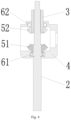
- the outer rotary shaft 3 with the outer shaft gear 52 is fitted around the inner rotary shaft 2 with the inner shaft gear 51, as shown in Figs. 2 and 3 , and then the inner rotary shaft 2 and the outer rotary shaft 3 are mounted to corresponding positions in the first half-sectional bracket portion, as shown in Fig.
- the intermediate gear 53 is engaged with the outer shaft gear 52 and the inner shaft gear 51 respectively by utilizing an external space, then the intermediate gear 53 is turned around the concentric axis of the outer rotary shaft 3 and the inner rotary shaft 2 that serves as a central axis, and thereby the intermediate gear 53 is mounted to a corresponding position in the first half-sectional bracket portion, as shown in Fig. 5 ; finally, the second half-section bracket portion and the first half-sectional bracket portion are assembled to form the gear bracket 4.
- the assembler can mount the gear transmission components into the gear bracket 4 easily, and the assembling efficiency is high.
- the outer circumference walls of the inner rotary shaft 2 and the outer rotary shaft 3 are respectively provided with an inner bearing pack 61 and an outer bearing pack 62 that are respectively arranged on the bottom wall and top wall of the gear bracket 4, the rotary shaft of the intermediate gear 53 is provided with an intermediate bearing pack 63 mounted on the side wall of the gear bracket 4, as shown in Figs. 1 and 5 .
- the inner bearing pack 61 between the outer circumference wall of the inner rotary shaft 2 and the gear bracket 4, radial support is provided to the inner rotary shaft 2, the accuracy of rotation of the inner rotary shaft 2 can be improved, and thereby a situation of instable transmission of the inner rotary shaft 2 can be avoided; moreover, in that way, the friction coefficient between the inner rotary shaft 2 and the gear bracket 4 in the process of rotation can be effectively decreased, the inner rotary shaft 2 can rotate smoothly in the gear bracket 4, and the user experience can be improved.
- the outer bearing pack 62 between the outer circumference wall of the rotating shaft 3 and the gear bracket 4 and arranging the intermediate bearing pack 63 between the outer circumference wall of the rotary shaft of the intermediate gear 53 and the gear bracket 4, the accuracy of rotation of the outer rotary shaft 3 and the rotary shaft of the intermediate gear 53 can be improved, the outer rotary shaft 3 and the rotary shaft of the intermediate gear 53 can rotate smoothly in the gear bracket 4, and thereby the user experience can be improved.
Landscapes
- Engineering & Computer Science (AREA)
- Power Engineering (AREA)
- Mechanical Engineering (AREA)
- Food Science & Technology (AREA)
- General Engineering & Computer Science (AREA)
- Food-Manufacturing Devices (AREA)
- Connection Of Motors, Electrical Generators, Mechanical Devices, And The Like (AREA)
- Gear Transmission (AREA)
Description
- The present disclosure relates to the field of household appliances, in particular to an electric motor and a food processor.
- As science and technology is developed continuously and people's living standard is improved continuously, food processors with a double-shaft beating function, such as wall breaking machines and soybean milk machines, etc., are applied more and more widely. In such a food processor, an electric motor rotates and drives two shafts arranged concentrically, and two blades in a mixing cup are in a transmission connection with the two shafts respectively, so that the two blades perform beating operation simultaneously.
- At present, the electric motor generally employs an external transmission mechanism to rotate and drive the two shafts arranged concentrically. Consequently, when the assembler assembles the food processor, the transmission mechanism may be injured or even damaged easily. Of course, after the food processor is assembled, interference to the transmission assembly may occur owing to loosening of other parts (e.g., electric wires) in the food processor. As a result, the normal operation of the transmission assembly is affected, and the service life of the entire machine is shortened.
-
CN 106 367 312 A discloses a fermentation tank mixing arrangement with a coaxial double-oar submersible agitator. The submersible motor comprises an inner shaft, an outer shaft, a first bevel gear, a second bevel gear and two sets of blades with opposite mounting directions. The first bevel gear and the second bevel gear are disposed inside the submersible motor, the edge of the rotor inside the submersible motor is provided with two sets of conical teeth respectively with the first bevel gear and the second bevel gear in order to allow different rotation speeds of the inner shaft and the outer shaft. The first bevel gear and the second bevel gear are synchronously rotated by the inner rotor of the submersible motor. Further state of the art is known fromCN 105 065 637 -
- To overcome the above-mentioned drawbacks or defects in the prior art, the present disclosure provides an electric motor and a food processor. The electric motor can effectively protect the gear transmission mechanism, is helpful for improving the reliability and service life of the gear transmission mechanism, and thereby improve the reliability and service life of the food processor.
- To attain the object described above, the present disclosure provides an electric motor for a food processor, which comprises a front end cover and a rotary output shaft extending out of the front end cover from an inner cavity of the electric motor, wherein the rotary output shaft comprises an inner rotary shaft and an outer rotary shaft that are arranged concentrically, a gear transmission mechanism is further provided inside the inner cavity of the electric motor, and the gear transmission mechanism is in a transmission connection with the inner rotary shaft and the outer rotary shaft respectively.
- The gear transmission mechanism comprises a gear bracket and gear transmission components, wherein the gear transmission components are accommodated in an inner cavity of the gear bracket, and the gear bracket is disposed in the inner cavity of the electric motor and fixedly mounted on the front end cover, wherein the inner rotary shaft extends through a bottom wall and a top wall of the gear bracket sequentially and extends out of a top wall of the front end cover, the outer rotary shaft is concentrically fitted outside the inner rotary shaft and extends out of the top wall of the gear bracket and the top wall of the front end cover, the gear transmission components comprise an inner shaft gear and an outer shaft gear that are fixedly fitted around outer circumference walls of the inner rotary shaft and the outer rotary shaft respectively, and the inner shaft gear and the outer shaft gear are in a transmission connection with each other and wherein the gear transmission mechanism comprises an intermediate gear, which is pivotally mounted on a side wall of the gear bracket and engaged with the inner shaft gear and the outer shaft gear respectively, wherein the gear bracket comprises a first half-sectional bracket portion and a second half-section bracket portion that are sectioned along a half section defined by a central axis of the intermediate gear and a concentric axis of the inner rotary shaft and the outer rotary shaft that orthogonally cross each other.
- Optionally, the gear bracket is an enclosed cubical bracket.
- Optionally, the outer circumference walls of the inner rotary shaft and the outer rotary shaft are respectively provided with an inner bearing pack and an outer bearing pack respectively arranged on the bottom wall and the top wall of the gear bracket, the rotary shaft of the intermediate gear is provided with an intermediate bearing pack mounted on the side wall of the gear bracket.
- Optionally, a bottom end of the inner shaft gear abuts against a top end of the inner bearing pack, a top end of the outer shaft gear abuts against a bottom end of the outer bearing pack, and the intermediate gear is engaged with the inner shaft gear and the outer shaft gear respectively.
- Optionally, all of the intermediate gear, the inner shaft gear, and the outer shaft gear are cone gears, and the horizontal inclination angles of the cone generatrices of the inner shaft gear and the outer shaft gear are not smaller than 45° and not greater than 60°.
- Optionally, the rotation speed ratio of the outer rotary shaft to the inner rotary shaft is not smaller than 1/5 and not greater than 1.
- The present disclosure further provides a food processor, which comprises an inner shaft stirring blade assembly, an outer shaft stirring blade assembly, and an electric motor, wherein the inner rotary shaft drives the inner shaft stirring blade assembly to rotate, and the outer shaft stirring blade assembly is in a transmission connection with the outer rotary shaft.
- With the above technical scheme, in the electric motor provided in the present disclosure, the inner rotary shaft and the outer rotary shaft, which are arranged concentrically, extend out of the front end cover of the electric motor, the inner rotary shaft and the outer rotary shaft are in a transmission connection via the gear transmission mechanism, and the gear transmission mechanism is accommodated in the inner cavity of the electric motor. Thus, the gear transmission mechanism is integrated in the electric motor, and is effectively protected. As a result, not only a situation of injury or damage to the gear transmission mechanism occurring owing to the carelessness of the assembler can be prevent, but also the interference to the double-shaft transmission assembly can be prevented when other parts (e.g., electric wires) in the food processor get loose. In that way, the reliability and service life of the gear transmission mechanism can be greatly improved, and the reliability and service life of the food processor can be improved.
- Other features and advantages of the present disclosure will be further detailed in the detailed description hereunder.
- The accompanying drawings are provided here to facilitate further understanding on the present disclosure, and constitute a part of this document. They are used in conjunction with the following detailed description to explain the present disclosure, but shall not be comprehended as constituting any limitation to the present disclosure. In the figures:
-
Fig. 1 is a general sectional view of the electric motor according to a preferred embodiment of the present disclosure; -
Figs. 2-5 are schematic diagrams illustrating the assembling process of the gear transmission components into the gear bracket, whereinFig. 2 is a sectional view illustrating the inner shaft gear and the inner bearing pack arranged on the outer circumference wall of the inner rotary shaft,Fig. 3 is a sectional view illustrating the outer rotary shaft with the outer shaft gear and the outer bearing pack fitted outside the inner rotary shaft,Fig. 4 is a sectional view illustrating the assembling of the inner rotary shaft and the outer rotary shaft into the first half-sectional bracket portion, and -
Fig. 5 is a sectional view illustrating the assembling of the intermediate gear with the intermediate bearing pack into the first half-sectional bracket portion after the intermediate gear is engaged with the inner shaft gear and the outer shaft gear respectively. - Hereunder some detailed description of the present disclosure will be detailed with reference to the accompanying drawings. It should be understood that the detailed description described here are only provided to describe and explain the present disclosure rather than constitute any limitation to the present disclosure.
- It is noted that the examples and the features in the examples in the present disclosure can be combined freely, provided that there is no confliction between them.
- In the present disclosure, unless otherwise specified, the words that denote directions or orientations, such as "above", "below", "top", and "bottom", etc., are usually used to describe the relative position relations among the components with respect to the direction as set forth in the accompanying drawings or the vertical, plumb, or gravity direction.
- Hereunder the present disclosure will be detailed in examples with reference to the accompanying drawings.
- In one aspect, the present disclosure provides an electric motor. As shown in
Fig. 1 , the electric motor comprises afront end cover 11 and a rotary output shaft extending out of thefront end cover 11 from an inner cavity of the electric motor, wherein the rotary output shaft comprises an innerrotary shaft 2 and an outerrotary shaft 3 that are arranged concentrically, a gear transmission mechanism is further provided inside the inner cavity of the electric motor, and the gear transmission mechanism is in a transmission connection with the innerrotary shaft 2 and the outerrotary shaft 3 respectively. Optionally, the rotation speed ratio of the outerrotary shaft 3 to the innerrotary shaft 2 is not smaller than 1/5 and not greater than 1. - In another aspect, the present disclosure provides a food processor. The food processor comprises an inner shaft stirring blade assembly, an outer shaft stirring blade assembly, and an electric motor, wherein the inner
rotary shaft 2 drives the inner shaft stirring blade assembly to rotate, and the outer shaft stirring blade assembly is in a transmission connection with the outerrotary shaft 3. Wherein the food processor may be a wall breaking machine, natural juice extractor, juice extractor, soybean milk machine, agitator, or any other household appliance, as long as the food processor is provided with an electric motor and has a food beating function. - In the technical scheme of the present disclosure, the inner
rotary shaft 2 and the outerrotary shaft 3 that are arranged concentrically respectively rotate and drive the inner shaft stirring blade assembly and the outer shaft stirring blade assembly, and the inner shaft stirring blade assembly and the outer shaft stirring blade assembly are disposed in the mixing cup of the food processor, the rotor of the electric motor rotates and drives the rotary output shaft to drive the double stirring blade assembly (i.e., the inner shaft stirring blade assembly and the outer shaft stirring blade assembly) to operate simultaneously so as to cut and beat the food accommodated in the mixing cup. Wherein, the double shaft transmission mechanism composed of the innerrotary shaft 2 and the outerrotary shaft 3 in transmission connection is disposed in the inner cavity of the electric motor, i.e., the double shaft transmission mechanism is integrated in the electric motor. Thus, when the assembler assembles the food processor, the double shaft transmission mechanism is protected effectively, and thereby a situation of injury or damage to the double shaft transmission mechanism owing to the carelessness of the assembler can be avoided; in addition, after the food processor is assembled, interference to the double shaft transmission assembly can be effectively prevented when other parts (e.g., electric wires) in the food processor get loose. In that way, not only the reliability and service life of the double shaft transmission mechanism can be improved so as to improve the reliability and service life of the entire machine, but also the yield of the food processor can be effectively improved. Moreover, by integrating the double shaft transmission mechanism in the electric motor, the assembling speed of the assembler can be effectively improved, i.e., the assembler only has to assemble the electric motor integrated with the double shaft transmission mechanism into the food processor, without assembling the double shaft transmission mechanism additionally. Thus, the production efficiency of the food processor can be greatly improved. Of course, by integrating the double shaft transmission mechanism inside the electric motor, an additional internal space for accommodating the double shaft transmission mechanism is omitted in the food processor. That is to say, the internal space occupied in the food processor can be effectively reduced, the entire machine is smaller and more compact; in addition, the transportation and storage cost of the food processor can be reduced since the footprint of the entire machine is reduced. - Specifically, the double shaft transmission mechanism is a gear transmission mechanism. In such an arrangement, the gear transmission mechanism has a more outstanding technical effect than other transmission structures, such as belt-wheel transmission mechanisms. Hereunder the technical effect of the double shaft transmission mechanism serving as a gear transmission mechanism will be described with a belt-wheel transmission mechanism as a comparative example. Specifically, a gear transmission mechanism realizes transmission by means of gear engagement, while a belt-wheel transmission mechanism requires a transmission belt between the wheels to realize transmission. Therefore, compared with a belt-wheel transmission mechanism, a gear transmission mechanism has a smaller and more compact structure since it doesn't require a transmission belt, and thereby the electric motor or even the entire machine is smaller and more compact. Furthermore, the transmission belt in a belt-wheel transmission mechanism gets slack gradually after years of operation, resulting in degradation or even loss of the transmission capability; in contrast, such a situation doesn't occur in a gear transmission mechanism. Therefore, compared with a belt-wheel transmission mechanism, the operation reliability of a gear transmission mechanism is higher, and the service life of a gear transmission mechanism is longer. Of course, since a gear transmission mechanism doesn't require a transmission belt for linkage, the transmission efficiency is higher.
- Optionally, the electric motor comprises an
inner rotor 13 and anouter stator 12, and the rotary shaft of theinner rotor 13 is the innerrotary shaft 2, as shown inFig. 1 . Therefore, compared with an electric motor with an outer rotor, an electric motor with aninner rotor 13 is smaller and more compact, and occupies a smaller space. Furthermore, the electric motor comprises aback end cover 14 fixed to the back end of theouter stator 12. - Specifically, the gear transmission mechanism comprises a
gear bracket 4 and a gear transmission component accommodated in the inner cavity of thegear bracket 4, thegear bracket 4 is disposed in the inner cavity of the electric motor and fixedly mounted on thefront end cover 11, as shown inFig. 1 . Thus, by connecting thegear bracket 4 to the front end cover 11 fixedly, thegear bracket 4 and the front end cover 11 forms an integral piece, so that the gear transmission components in the inner cavity of the bracket can carry out transmission smoothly, and thereby the innerrotary shaft 2 can smoothly transfer the rotational kinetic energy to the outerrotary shaft 3 via the gear transmission component. That is to say, the transmission between the innerrotary shaft 2 and the outerrotary shaft 3 is more smooth and stable, and the user experience can be improved. Of course, the smooth and stable transmission of the gear transmission components can effectively reduce the operation noise produced during gear transmission and is helpful for improving user experience. Moreover, since the gear transmission mechanism is accommodated in the inner cavity of thefront end cover 11, it doesn't affect the transmission efficiency of the rotor and the stator in the electric motor. - Furthermore, as shown in
Fig. 1 , thegear bracket 4 is an enclosed cubical bracket. Specifically, to improve the reliability and service life of the gear transmission components, usually a lubricant is applied on the gear transmission components. Therefore, by configuring thegear bracket 4 into an enclosed bracket, interference to other parts in the electric motor owing to dripping or splashing of the lubricant applied on the gear transmission component can be effectively avoided, and the reliability and service life of the electric motor can be improved. Moreover, thegear bracket 4 may be in a spheroidal shape or other shape, besides cubical shape. - The inner
rotary shaft 2 extends through a bottom wall and a top wall of thegear bracket 4 sequentially and extends out of a top wall of thefront end cover 11, the outerrotary shaft 3 is concentrically fitted outside the innerrotary shaft 2 and extends out of the top wall of thegear bracket 4 and the top wall of thefront end cover 11, as shown inFigs. 1-4 , the gear transmission components comprise aninner shaft gear 51 and anouter shaft gear 52 that are fixedly fitted around outer circumference walls of the innerrotary shaft 2 and the outerrotary shaft 3 respectively, and theinner shaft gear 51 and theouter shaft gear 52 are in a transmission connection with each other. - Furthermore, the gear transmission mechanism further comprises an
intermediate gear 53 as shown inFigs. 1-5 , which is pivotally mounted on a side wall of thegear bracket 4 and engaged with theinner shaft gear 51 and theouter shaft gear 52 respectively. In such an arrangement, the outerrotary shaft 3 can rotate in a reverse direction with respect to the innerrotary shaft 2, and thereby the inner shaft stirring blade assembly and the outer shaft stirring blade assembly have rotation directions reversed to each other. Thus, the rotation speeds of the double stirring blade assembly in directions reversed to each other are stacked, and the cutting speed of the double stirring blade assembly with respect to the food particles is greatly increased. Therefore, the food can be cut to a finer state, and the rate of juice extraction from the food and the drinking taste can be improved. In other words, for an electric motor in which the innerrotary shaft 2 and the outerrotary shaft 3 rotate in directions reverse to each other, by greatly decreasing the rotation speed of therotor 13 in the electric motor (e.g., to 1/2 of the original rotation speed), a food beating and crushing effect can also be attained even when the innerrotary shaft 2 and the outerrotary shaft 3 rotate in the same direction. By decreasing the rotor speed, the food processor can achieve the original food crushing effect while the noise produced during the operation of the main body of the electric motor is reduced. Furthermore, the decreased rotor speed can result in decreased rotation speed of the double stirring blade assembly, and the vibration and noise produced during the food cutting operation of the double stirring blade assembly can be reduced. - Specifically, all of the
intermediate gear 53, theinner shaft gear 51, and theouter shaft gear 52 are cone gears. Wherein theintermediate gear 53, theinner shaft gear 51, and theouter shaft gear 52 may be straight-tooth cone gears or skewed-tooth cone gears, or other appropriate cone gears, such as arc-tooth cone gears. - In addition, as shown in
Fig. 1 , the horizontal inclination angles of the cone generatrices of theinner shaft gear 51 and theouter shaft gear 52 shall not be smaller than 45° and not greater than 60° respectively. Wherein the concentric axis of theinner shaft gear 51 and theouter shaft gear 52 and the central axis of theintermediate gear 53 orthogonally cross each other, and the horizontal inclination angle of the cone generatrix of theinner shaft gear 51, theouter shaft gear 52 or theintermediate gear 53 refers to an acute included angle between the cone generatrix of the gear and the horizontal plane when the gear is placed horizontally (i.e., the central axis of the gear is perpendicular to the horizontal plane). Thus, the sum of the horizontal inclination angle of the cone generatrix of theinner shaft gear 51 or theouter shaft gear 52 and the horizontal inclination angle of the cone generatrix of theintermediate gear 53 shall be 90°. In that way, if the horizontal inclination angles of the cone generatrices of theinner shaft gear 51 and theouter shaft gear 52 are 60° respectively, the horizontal inclination angle of the cone generatrix of theintermediate gear 53 is 30°. Optionally, the horizontal inclination angles of the cone generatrices of theinner shaft gear 51 and theouter shaft gear 52 are 45° respectively. Thus, theinner shaft gear 51, theouter shaft gear 52, and theintermediate gear 53 can be designed to be interchangeable, i.e., the assembler has to mount gears to the positions where gears are to be mounted, without speeding any additional time and effort to artificially judge the types of the gears and the corresponding mounting positions. Furthermore, the horizontal inclination angles of the cone generatrices of theinner shaft gear 51 and theouter shaft gear 52 are greater than 45° and not greater than 60° respectively, i.e., the horizontal inclination angle of the cone generatrix of theintermediate gear 53 is smaller than 45°. Thus, theintermediate gear 53 may be designed to be smaller, and the height of thegear bracket 4 may be designed to be smaller, and thereby the structure of the electric motor can be smaller and more compact. Of course, the space occupied by the electric motor is smaller, the accommodating space of the food processor can be reduced, and thereby the transportation and storage cost of the entire machine can be reduced. - It should be noted that there are a variety of ways to arrange the gear transmission components. For example, the above-mentioned
inner shaft gear 51 andouter shaft gear 52 are engaged and carry out transmission via theintermediate gear 53; or an outer gear may be provided on the innerrotary shaft 2, an inner gear may be formed on the bottom end of the outerrotary shaft 3, a connecting gear may be pivotally arranged on the bottom wall of thegear bracket 4 and engaged with the inner gear and the outer gear respectively. - Optionally, the speed ratio of the outer
rotary shaft 3 to the innerrotary shaft 2 shall not be smaller than 1/5 and not greater than 1. Thus, the food accommodated in the mixing cup can be cut to a finer state by the double stirring blade assembly, and thereby a better drinking state can be obtained while more juice can be squeezed from the food, and the user experience can be improved greatly. Furthermore, the speed ratio of the outerrotary shaft 3 to the innerrotary shaft 2 shall not be smaller than 1/3 and not greater than 3/4. It can be understood that the higher the speed ratio of the outerrotary shaft 3 to the innerrotary shaft 2 is, the better the food beating and crushing effect of the double stirring blade assembly is; but the speed of impact of the food on the mixing cup body under the driving action of the high-speed double stirring blade assembly will be increased, and thereby the noise produced during the operation of the entire machine will be increased. Therefore, by confining the speed ratio of the outerrotary shaft 3 to the innerrotary shaft 2 to the above-mentioned preferred range, not only a good food beating and crushing effect can be attained, but also the noise during the beating operation can be reduced. - To facilitate the assembler to mount the gear transmission components into the
gear bracket 4, as shown inFigs. 1-5 , thegear bracket 4 comprises a first half-sectional bracket portion and a second half-section bracket portion that are sectioned along a half section defined by the central axis of theintermediate gear 53 and the concentric axis of the innerrotary shaft 2 and the outerrotary shaft 3 that are orthogonally cross each other. Specifically, the outerrotary shaft 3 with theouter shaft gear 52 is fitted around the innerrotary shaft 2 with theinner shaft gear 51, as shown inFigs. 2 and3 , and then the innerrotary shaft 2 and the outerrotary shaft 3 are mounted to corresponding positions in the first half-sectional bracket portion, as shown inFig. 4 ; theintermediate gear 53 is engaged with theouter shaft gear 52 and theinner shaft gear 51 respectively by utilizing an external space, then theintermediate gear 53 is turned around the concentric axis of the outerrotary shaft 3 and the innerrotary shaft 2 that serves as a central axis, and thereby theintermediate gear 53 is mounted to a corresponding position in the first half-sectional bracket portion, as shown inFig. 5 ; finally, the second half-section bracket portion and the first half-sectional bracket portion are assembled to form thegear bracket 4. With such a ground-breaking assembling method, the assembler can mount the gear transmission components into thegear bracket 4 easily, and the assembling efficiency is high. - Optionally, the outer circumference walls of the inner
rotary shaft 2 and the outerrotary shaft 3 are respectively provided with aninner bearing pack 61 and anouter bearing pack 62 that are respectively arranged on the bottom wall and top wall of thegear bracket 4, the rotary shaft of theintermediate gear 53 is provided with anintermediate bearing pack 63 mounted on the side wall of thegear bracket 4, as shown inFigs. 1 and5 . Thus, by arranging theinner bearing pack 61 between the outer circumference wall of the innerrotary shaft 2 and thegear bracket 4, radial support is provided to the innerrotary shaft 2, the accuracy of rotation of the innerrotary shaft 2 can be improved, and thereby a situation of instable transmission of the innerrotary shaft 2 can be avoided; moreover, in that way, the friction coefficient between the innerrotary shaft 2 and thegear bracket 4 in the process of rotation can be effectively decreased, the innerrotary shaft 2 can rotate smoothly in thegear bracket 4, and the user experience can be improved. Likewise, by arranging theouter bearing pack 62 between the outer circumference wall of therotating shaft 3 and thegear bracket 4 and arranging theintermediate bearing pack 63 between the outer circumference wall of the rotary shaft of theintermediate gear 53 and thegear bracket 4, the accuracy of rotation of the outerrotary shaft 3 and the rotary shaft of theintermediate gear 53 can be improved, the outerrotary shaft 3 and the rotary shaft of theintermediate gear 53 can rotate smoothly in thegear bracket 4, and thereby the user experience can be improved. - In addition, as shown in
Fig. 1 , the bottom end of theinner shaft gear 51 abuts against the top end of theinner bearing pack 61, the top end of theouter shaft gear 52 abuts against the bottom end of theouter bearing pack 62, and theintermediate gear 53 is engaged with theinner shaft gear 51 and theouter shaft gear 52 respectively. Thus, a situation of axial displacement (i.e., upward and downward movement) of theouter shaft gear 52 and theinner shaft gear 51 can be effectively prevented during the operation of the electric motor, the transmission stability and reliability of the gear transmission mechanism can be improved, and thereby the reliability of the entire machine can be improved. - It should be noted particularly that the other components and their functions of the electric motor and food processor according to the examples of the present disclosure are well known to those having ordinary skilled in the art, and will not be detailed here to reduce redundancy.
- While the present disclosure is described above in some preferred examples, the present disclosure is not limited to those preferred embodiments.
- In addition, it should be noted that the specific technical features described in above specific detailed description may be combined within the scope of the invention. To avoid unnecessary repetition, various possible combinations are not described specifically in the present disclosure.
- Moreover, different embodiments of the present disclosure may also be combined, as long as the combinations don't deviate from the scope of the present invention, which is defined by the appended claims.
| 2 | Inner | 3 | |
| 4 | | ||
| 11 | | 12 | |
| 13 | | 14 | |
| 51 | | 52 | |
| 53 | | 61 | |
| 62 | | 63 | Intermediate bearing pack |
Claims (7)
- An electric motor for a food processor, comprising
a front end cover (11);an output rotary shaft, extending out of the front end cover (11) from an inner cavity of the electric motor, wherein the output rotary shaft comprises an inner rotary shaft (2) and an outer rotary shaft (3) that are arranged concentrically; anda gear transmission mechanism, provided inside the inner cavity of the electric motor, and the gear transmission mechanism is in a transmission connection with the inner rotary shaft (2) and the outer rotary shaft (3), wherein the gear transmission mechanism comprises a gear bracket (4) and a gear transmission component, and the gear bracket (4) is disposed in the inner cavity of the electric motor and fixedly mounted on the front end cover (11) , the outer rotary shaft (3) is concentrically fitted outside the inner rotary shaft (2) and the top wall of the front end cover (11), the gear transmission component comprises an inner shaft gear (51) and an outer shaft gear (52), the inner shaft gear (51) is fixedly fitted around an outer circumference wall of the inner rotary shaft (2) , and the inner shaft gear (51) and the outer shaft gear (52) are in a transmission connection with each other and,wherein the gear transmission mechanism comprises an intermediate gear (53), which is pivotally mounted on a side wall of the gear bracket (4) and engaged with the inner shaft gear (51) and the outer shaft gear (52) respectively,wherein the gear transmission component is accommodated in an inner cavity of the gear bracket (4),wherein the inner rotary shaft (2) extends through a bottom wall and a top wall of the gear bracket (4) sequentially and extends out of a top wall of the front end cover (11),wherein the outer rotary shaft (3) extends out of the top wall of the gear bracket (4),wherein the outer shaft gear (52) is fixedly fitted on an outer circumference wall of the outer rotary shaft (3),wherein the gear bracket (4) comprises a first half-sectional bracket portion and a second half-section bracket portion that are sectioned along a half section, wherein the half section is defined by a central axis of the intermediate gear (53) and a concentric axis of the inner rotary shaft (2) and the outer rotary shaft (3), wherein the two axes orthogonally cross each other. - The electric motor of claim 1, wherein the gear bracket (4) is an enclosed cubical bracket.
- The electric motor of claim 1 or 2, wherein the outer circumference walls of the inner rotary shaft (2) and the outer rotary shaft (3) are respectively provided with an inner bearing assembly (61) and an outer bearing assembly (62), wherein the inner bearing assembly (61) and the outer bearing assembly (62) are respectively arranged on the bottom wall and the top wall of the gear bracket (4), a rotary shaft of the intermediate gear (53) is provided with an intermediate bearing assembly (63), wherein the intermediate bearing assembly (63) is mounted on the side wall of the gear bracket (4).
- The electric motor of claim 3, wherein a bottom end of the inner shaft gear (51) abuts against a top end of the inner bearing assembly (61), a top end of the outer shaft gear (52) abuts against a bottom end of the outer bearing assembly (62), and the intermediate gear (53) is engaged with the inner shaft gear (51) and the outer shaft gear (52) respectively.
- The electric motor of any one of claims 1 to 2, wherein all of the intermediate gear (53), the inner shaft gear (51), and the outer shaft gear (52) are bevel gears, and inclination angles of the cone generatrices of the inner shaft gear (51) and the outer shaft gear (52) are not smaller than 45° and not greater than 60°.
- The electric motor of any one of claims 1 to 5, wherein a ratio of a rotation speed of the outer rotary shaft (3) to a rotation speed of the inner rotary shaft (2) is not smaller than 1/5 and not greater than 1.
- A food processor, comprising an inner shaft stirring blade assembly, an outer shaft stirring blade assembly, and the electric motor of any of claims 1-6, wherein the inner rotary shaft (2) drives the inner shaft stirring blade assembly to rotate, and the outer shaft stirring blade assembly is in a transmission connection with the outer rotary shaft (3).
Applications Claiming Priority (3)
| Application Number | Priority Date | Filing Date | Title |
|---|---|---|---|
| CN201820250006.8U CN207994817U (en) | 2018-02-11 | 2018-02-11 | Motor and cooking machine |
| CN201810140188.8A CN110165825B (en) | 2018-02-11 | 2018-02-11 | Motors and Blenders |
| PCT/CN2018/099243 WO2019153672A1 (en) | 2018-02-11 | 2018-08-07 | Electric motor and food processor |
Publications (3)
| Publication Number | Publication Date |
|---|---|
| EP3731382A1 EP3731382A1 (en) | 2020-10-28 |
| EP3731382A4 EP3731382A4 (en) | 2021-02-24 |
| EP3731382B1 true EP3731382B1 (en) | 2025-05-07 |
Family
ID=67549183
Family Applications (1)
| Application Number | Title | Priority Date | Filing Date |
|---|---|---|---|
| EP18905845.6A Active EP3731382B1 (en) | 2018-02-11 | 2018-08-07 | Electric motor and food processor |
Country Status (4)
| Country | Link |
|---|---|
| EP (1) | EP3731382B1 (en) |
| JP (1) | JP7069329B2 (en) |
| KR (1) | KR102423224B1 (en) |
| WO (1) | WO2019153672A1 (en) |
Citations (1)
| Publication number | Priority date | Publication date | Assignee | Title |
|---|---|---|---|---|
| ES2339098B1 (en) * | 2009-09-23 | 2011-05-27 | Gometrics, S.L. | POWER TRANSMISSION SYSTEM FOR COAXIAL AXLES. |
Family Cites Families (15)
| Publication number | Priority date | Publication date | Assignee | Title |
|---|---|---|---|---|
| JPH0670518A (en) * | 1991-08-12 | 1994-03-11 | Shiroo Uchida | Concentric multiaxial mechanism motor |
| DE4232934C2 (en) * | 1992-10-01 | 1996-03-28 | Mavag Verfahrenstech Ag | Double impeller for stirring sterile liquids |
| JPH10257730A (en) * | 1997-03-07 | 1998-09-25 | Shinko Electric Co Ltd | Concentric multi-axis motor |
| JP2003206997A (en) * | 2002-01-16 | 2003-07-25 | Seiko Epson Corp | Small speed reducer and geared motor equipped with the same |
| CN201018351Y (en) * | 2006-11-14 | 2008-02-06 | 綦学尧 | Coaxial dual-speed output planetary gear speed reducing motor |
| CN201368189Y (en) * | 2009-02-26 | 2009-12-23 | 焦佃中 | Coaxial positive and negative rotating bidirectional driving gear case |
| CN201883428U (en) * | 2010-12-16 | 2011-06-29 | 彭文 | Bidirectional mixing boring tool for mixing pile machine |
| CN102677427B (en) | 2012-05-24 | 2015-01-21 | 常州至精精机有限公司 | Washing machine driver |
| CN102758883A (en) * | 2012-07-09 | 2012-10-31 | 王学明 | Dill-rod-free drill machine transfer case |
| US20150362043A1 (en) * | 2014-06-12 | 2015-12-17 | Benjamin J. Podurgiel, Iii | Gearing system |
| CN204429390U (en) | 2014-12-30 | 2015-07-01 | 开县百安居建材有限公司 | Double drum crusher |
| CN105065637A (en) | 2015-08-13 | 2015-11-18 | 宁波市鄞州蓝茵工业产品设计有限公司 | Coaxial bidirectional stirring device |
| CN105498592B (en) * | 2016-01-29 | 2018-01-30 | 中国矿业大学 | A kind of planet gear type friction material batch mixer |
| CN106367312B (en) * | 2016-11-04 | 2019-04-02 | 中国科学院青岛生物能源与过程研究所 | A coaxial twin-paddle submersible agitator for large fermenters |
| CN106732065A (en) | 2016-12-21 | 2017-05-31 | 安庆市大成防腐保温材料有限责任公司 | A kind of latex mixer |
-
2018
- 2018-08-07 EP EP18905845.6A patent/EP3731382B1/en active Active
- 2018-08-07 JP JP2020542806A patent/JP7069329B2/en active Active
- 2018-08-07 KR KR1020207023173A patent/KR102423224B1/en active Active
- 2018-08-07 WO PCT/CN2018/099243 patent/WO2019153672A1/en not_active Ceased
Patent Citations (1)
| Publication number | Priority date | Publication date | Assignee | Title |
|---|---|---|---|---|
| ES2339098B1 (en) * | 2009-09-23 | 2011-05-27 | Gometrics, S.L. | POWER TRANSMISSION SYSTEM FOR COAXIAL AXLES. |
Also Published As
| Publication number | Publication date |
|---|---|
| WO2019153672A1 (en) | 2019-08-15 |
| KR102423224B1 (en) | 2022-07-20 |
| EP3731382A4 (en) | 2021-02-24 |
| EP3731382A1 (en) | 2020-10-28 |
| JP7069329B2 (en) | 2022-05-17 |
| KR20200104905A (en) | 2020-09-04 |
| JP2021513832A (en) | 2021-05-27 |
Similar Documents
| Publication | Publication Date | Title |
|---|---|---|
| JP5274703B1 (en) | Washing machine | |
| US11223255B2 (en) | Electric motor and food processor | |
| CN110165825B (en) | Motors and Blenders | |
| CN111053469B (en) | Rotating mechanism and food processor | |
| EP3731382A1 (en) | Electric motor and food processor | |
| CN208822574U (en) | Motor drive component and cooking machine | |
| CN110833305A (en) | Juicer and Blender Compatible Power Units | |
| WO2021208641A1 (en) | Blender | |
| CN1923103A (en) | Food processor | |
| CN216724286U (en) | A low noise food processor | |
| KR102943224B1 (en) | Driving apparatus for blender and juicer in one | |
| CN207994807U (en) | Motors and Blenders | |
| CN214946129U (en) | Gear speed reducer capable of effectively reducing noise in operation | |
| CN110811279A (en) | Compatible power device of juice extractor and mixer | |
| CN208447357U (en) | food processor | |
| CN207994818U (en) | Motor and cooking machine | |
| CN207910607U (en) | Motor and cooking machine | |
| CN208447323U (en) | food processor | |
| CN207994816U (en) | Motor and cooking machine | |
| CN211212546U (en) | Compatible power device of juice extractor and mixer | |
| CN208447350U (en) | food processor | |
| CN215272195U (en) | Food processor host and food processor | |
| CN207994815U (en) | Motor and cooking machine | |
| CN207994808U (en) | Motor drive component and cooking machine | |
| CN208461609U (en) | Motor Drive Components and Blenders |
Legal Events
| Date | Code | Title | Description |
|---|---|---|---|
| STAA | Information on the status of an ep patent application or granted ep patent |
Free format text: STATUS: THE INTERNATIONAL PUBLICATION HAS BEEN MADE |
|
| PUAI | Public reference made under article 153(3) epc to a published international application that has entered the european phase |
Free format text: ORIGINAL CODE: 0009012 |
|
| STAA | Information on the status of an ep patent application or granted ep patent |
Free format text: STATUS: REQUEST FOR EXAMINATION WAS MADE |
|
| 17P | Request for examination filed |
Effective date: 20200724 |
|
| AK | Designated contracting states |
Kind code of ref document: A1 Designated state(s): AL AT BE BG CH CY CZ DE DK EE ES FI FR GB GR HR HU IE IS IT LI LT LU LV MC MK MT NL NO PL PT RO RS SE SI SK SM TR |
|
| AX | Request for extension of the european patent |
Extension state: BA ME |
|
| A4 | Supplementary search report drawn up and despatched |
Effective date: 20210126 |
|
| RIC1 | Information provided on ipc code assigned before grant |
Ipc: A47J 43/08 20060101ALN20210120BHEP Ipc: H02K 7/116 20060101AFI20210120BHEP Ipc: F16H 1/22 20060101ALI20210120BHEP |
|
| DAV | Request for validation of the european patent (deleted) | ||
| DAX | Request for extension of the european patent (deleted) | ||
| STAA | Information on the status of an ep patent application or granted ep patent |
Free format text: STATUS: EXAMINATION IS IN PROGRESS |
|
| 17Q | First examination report despatched |
Effective date: 20230102 |
|
| REG | Reference to a national code |
Ref country code: DE Ref legal event code: R079 Free format text: PREVIOUS MAIN CLASS: H02K0007100000 Ipc: H02K0007116000 Ref document number: 602018081831 Country of ref document: DE |
|
| GRAP | Despatch of communication of intention to grant a patent |
Free format text: ORIGINAL CODE: EPIDOSNIGR1 |
|
| STAA | Information on the status of an ep patent application or granted ep patent |
Free format text: STATUS: GRANT OF PATENT IS INTENDED |
|
| RIC1 | Information provided on ipc code assigned before grant |
Ipc: A47J 43/08 20060101ALN20250203BHEP Ipc: F16H 1/22 20060101ALI20250203BHEP Ipc: H02K 7/116 20060101AFI20250203BHEP |
|
| INTG | Intention to grant announced |
Effective date: 20250213 |
|
| RIN1 | Information on inventor provided before grant (corrected) |
Inventor name: YANG, GUANGREN Inventor name: YANG, ZHENFENG Inventor name: PANG, CONGSHAN Inventor name: CHEN, LIANCHENG Inventor name: LIANG, XIANTANG |
|
| GRAS | Grant fee paid |
Free format text: ORIGINAL CODE: EPIDOSNIGR3 |
|
| GRAA | (expected) grant |
Free format text: ORIGINAL CODE: 0009210 |
|
| STAA | Information on the status of an ep patent application or granted ep patent |
Free format text: STATUS: THE PATENT HAS BEEN GRANTED |
|
| AK | Designated contracting states |
Kind code of ref document: B1 Designated state(s): AL AT BE BG CH CY CZ DE DK EE ES FI FR GB GR HR HU IE IS IT LI LT LU LV MC MK MT NL NO PL PT RO RS SE SI SK SM TR |
|
| REG | Reference to a national code |
Ref country code: GB Ref legal event code: FG4D |
|
| REG | Reference to a national code |
Ref country code: CH Ref legal event code: EP |
|
| REG | Reference to a national code |
Ref country code: DE Ref legal event code: R096 Ref document number: 602018081831 Country of ref document: DE |
|
| REG | Reference to a national code |
Ref country code: IE Ref legal event code: FG4D |
|
| REG | Reference to a national code |
Ref country code: NL Ref legal event code: MP Effective date: 20250507 |
|
| PG25 | Lapsed in a contracting state [announced via postgrant information from national office to epo] |
Ref country code: ES Free format text: LAPSE BECAUSE OF FAILURE TO SUBMIT A TRANSLATION OF THE DESCRIPTION OR TO PAY THE FEE WITHIN THE PRESCRIBED TIME-LIMIT Effective date: 20250507 Ref country code: PT Free format text: LAPSE BECAUSE OF FAILURE TO SUBMIT A TRANSLATION OF THE DESCRIPTION OR TO PAY THE FEE WITHIN THE PRESCRIBED TIME-LIMIT Effective date: 20250908 Ref country code: FI Free format text: LAPSE BECAUSE OF FAILURE TO SUBMIT A TRANSLATION OF THE DESCRIPTION OR TO PAY THE FEE WITHIN THE PRESCRIBED TIME-LIMIT Effective date: 20250507 |
|
| PGFP | Annual fee paid to national office [announced via postgrant information from national office to epo] |
Ref country code: DE Payment date: 20250827 Year of fee payment: 8 |
|
| REG | Reference to a national code |
Ref country code: LT Ref legal event code: MG9D |
|
| PG25 | Lapsed in a contracting state [announced via postgrant information from national office to epo] |
Ref country code: NO Free format text: LAPSE BECAUSE OF FAILURE TO SUBMIT A TRANSLATION OF THE DESCRIPTION OR TO PAY THE FEE WITHIN THE PRESCRIBED TIME-LIMIT Effective date: 20250807 Ref country code: GR Free format text: LAPSE BECAUSE OF FAILURE TO SUBMIT A TRANSLATION OF THE DESCRIPTION OR TO PAY THE FEE WITHIN THE PRESCRIBED TIME-LIMIT Effective date: 20250808 |
|
| PG25 | Lapsed in a contracting state [announced via postgrant information from national office to epo] |
Ref country code: PL Free format text: LAPSE BECAUSE OF FAILURE TO SUBMIT A TRANSLATION OF THE DESCRIPTION OR TO PAY THE FEE WITHIN THE PRESCRIBED TIME-LIMIT Effective date: 20250507 Ref country code: NL Free format text: LAPSE BECAUSE OF FAILURE TO SUBMIT A TRANSLATION OF THE DESCRIPTION OR TO PAY THE FEE WITHIN THE PRESCRIBED TIME-LIMIT Effective date: 20250507 |
|
| REG | Reference to a national code |
Ref country code: AT Ref legal event code: MK05 Ref document number: 1793599 Country of ref document: AT Kind code of ref document: T Effective date: 20250507 |
|
| PG25 | Lapsed in a contracting state [announced via postgrant information from national office to epo] |
Ref country code: BG Free format text: LAPSE BECAUSE OF FAILURE TO SUBMIT A TRANSLATION OF THE DESCRIPTION OR TO PAY THE FEE WITHIN THE PRESCRIBED TIME-LIMIT Effective date: 20250507 |
|
| PGFP | Annual fee paid to national office [announced via postgrant information from national office to epo] |
Ref country code: GB Payment date: 20250826 Year of fee payment: 8 |
|
| PG25 | Lapsed in a contracting state [announced via postgrant information from national office to epo] |
Ref country code: HR Free format text: LAPSE BECAUSE OF FAILURE TO SUBMIT A TRANSLATION OF THE DESCRIPTION OR TO PAY THE FEE WITHIN THE PRESCRIBED TIME-LIMIT Effective date: 20250507 |
|
| PG25 | Lapsed in a contracting state [announced via postgrant information from national office to epo] |
Ref country code: AT Free format text: LAPSE BECAUSE OF FAILURE TO SUBMIT A TRANSLATION OF THE DESCRIPTION OR TO PAY THE FEE WITHIN THE PRESCRIBED TIME-LIMIT Effective date: 20250507 |
|
| PGFP | Annual fee paid to national office [announced via postgrant information from national office to epo] |
Ref country code: FR Payment date: 20250826 Year of fee payment: 8 |
|
| PG25 | Lapsed in a contracting state [announced via postgrant information from national office to epo] |
Ref country code: RS Free format text: LAPSE BECAUSE OF FAILURE TO SUBMIT A TRANSLATION OF THE DESCRIPTION OR TO PAY THE FEE WITHIN THE PRESCRIBED TIME-LIMIT Effective date: 20250807 |
|
| PG25 | Lapsed in a contracting state [announced via postgrant information from national office to epo] |
Ref country code: IS Free format text: LAPSE BECAUSE OF FAILURE TO SUBMIT A TRANSLATION OF THE DESCRIPTION OR TO PAY THE FEE WITHIN THE PRESCRIBED TIME-LIMIT Effective date: 20250907 |
|
| PG25 | Lapsed in a contracting state [announced via postgrant information from national office to epo] |
Ref country code: LV Free format text: LAPSE BECAUSE OF FAILURE TO SUBMIT A TRANSLATION OF THE DESCRIPTION OR TO PAY THE FEE WITHIN THE PRESCRIBED TIME-LIMIT Effective date: 20250507 |
|
| PG25 | Lapsed in a contracting state [announced via postgrant information from national office to epo] |
Ref country code: DK Free format text: LAPSE BECAUSE OF FAILURE TO SUBMIT A TRANSLATION OF THE DESCRIPTION OR TO PAY THE FEE WITHIN THE PRESCRIBED TIME-LIMIT Effective date: 20250507 Ref country code: SM Free format text: LAPSE BECAUSE OF FAILURE TO SUBMIT A TRANSLATION OF THE DESCRIPTION OR TO PAY THE FEE WITHIN THE PRESCRIBED TIME-LIMIT Effective date: 20250507 |
|
| PG25 | Lapsed in a contracting state [announced via postgrant information from national office to epo] |
Ref country code: CZ Free format text: LAPSE BECAUSE OF FAILURE TO SUBMIT A TRANSLATION OF THE DESCRIPTION OR TO PAY THE FEE WITHIN THE PRESCRIBED TIME-LIMIT Effective date: 20250507 |
|
| PG25 | Lapsed in a contracting state [announced via postgrant information from national office to epo] |
Ref country code: EE Free format text: LAPSE BECAUSE OF FAILURE TO SUBMIT A TRANSLATION OF THE DESCRIPTION OR TO PAY THE FEE WITHIN THE PRESCRIBED TIME-LIMIT Effective date: 20250507 |
|
| PG25 | Lapsed in a contracting state [announced via postgrant information from national office to epo] |
Ref country code: SK Free format text: LAPSE BECAUSE OF FAILURE TO SUBMIT A TRANSLATION OF THE DESCRIPTION OR TO PAY THE FEE WITHIN THE PRESCRIBED TIME-LIMIT Effective date: 20250507 Ref country code: RO Free format text: LAPSE BECAUSE OF FAILURE TO SUBMIT A TRANSLATION OF THE DESCRIPTION OR TO PAY THE FEE WITHIN THE PRESCRIBED TIME-LIMIT Effective date: 20250507 |
|
| PG25 | Lapsed in a contracting state [announced via postgrant information from national office to epo] |
Ref country code: IT Free format text: LAPSE BECAUSE OF FAILURE TO SUBMIT A TRANSLATION OF THE DESCRIPTION OR TO PAY THE FEE WITHIN THE PRESCRIBED TIME-LIMIT Effective date: 20250507 |
|
| REG | Reference to a national code |
Ref country code: DE Ref legal event code: R097 Ref document number: 602018081831 Country of ref document: DE |
|
| PLBE | No opposition filed within time limit |
Free format text: ORIGINAL CODE: 0009261 |
|
| STAA | Information on the status of an ep patent application or granted ep patent |
Free format text: STATUS: NO OPPOSITION FILED WITHIN TIME LIMIT |
|
| REG | Reference to a national code |
Ref country code: CH Ref legal event code: L10 Free format text: ST27 STATUS EVENT CODE: U-0-0-L10-L00 (AS PROVIDED BY THE NATIONAL OFFICE) Effective date: 20260318 |
|
| REG | Reference to a national code |
Ref country code: CH Ref legal event code: H13 Free format text: ST27 STATUS EVENT CODE: U-0-0-H10-H13 (AS PROVIDED BY THE NATIONAL OFFICE) Effective date: 20260324 |
|
| PG25 | Lapsed in a contracting state [announced via postgrant information from national office to epo] |
Ref country code: MC Free format text: LAPSE BECAUSE OF FAILURE TO SUBMIT A TRANSLATION OF THE DESCRIPTION OR TO PAY THE FEE WITHIN THE PRESCRIBED TIME-LIMIT Effective date: 20250507 |
|
| 26N | No opposition filed |
Effective date: 20260210 |
|
| PG25 | Lapsed in a contracting state [announced via postgrant information from national office to epo] |
Ref country code: LU Free format text: LAPSE BECAUSE OF NON-PAYMENT OF DUE FEES Effective date: 20250807 |
|
| PG25 | Lapsed in a contracting state [announced via postgrant information from national office to epo] |
Ref country code: CH Free format text: LAPSE BECAUSE OF NON-PAYMENT OF DUE FEES Effective date: 20250831 |
|
| REG | Reference to a national code |
Ref country code: BE Ref legal event code: MM Effective date: 20250831 |
|
| PG25 | Lapsed in a contracting state [announced via postgrant information from national office to epo] |
Ref country code: LT Free format text: LAPSE BECAUSE OF FAILURE TO SUBMIT A TRANSLATION OF THE DESCRIPTION OR TO PAY THE FEE WITHIN THE PRESCRIBED TIME-LIMIT Effective date: 20250507 |
|
| PG25 | Lapsed in a contracting state [announced via postgrant information from national office to epo] |
Ref country code: BE Free format text: LAPSE BECAUSE OF NON-PAYMENT OF DUE FEES Effective date: 20250831 Ref country code: IE Free format text: LAPSE BECAUSE OF NON-PAYMENT OF DUE FEES Effective date: 20250807 |
|
| PG25 | Lapsed in a contracting state [announced via postgrant information from national office to epo] |
Ref country code: SE Free format text: LAPSE BECAUSE OF FAILURE TO SUBMIT A TRANSLATION OF THE DESCRIPTION OR TO PAY THE FEE WITHIN THE PRESCRIBED TIME-LIMIT Effective date: 20250507 |