EP3731378A1 - Stator of rotary machine - Google Patents
Stator of rotary machine Download PDFInfo
- Publication number
- EP3731378A1 EP3731378A1 EP18894629.7A EP18894629A EP3731378A1 EP 3731378 A1 EP3731378 A1 EP 3731378A1 EP 18894629 A EP18894629 A EP 18894629A EP 3731378 A1 EP3731378 A1 EP 3731378A1
- Authority
- EP
- European Patent Office
- Prior art keywords
- coil
- segment
- slot
- receiving
- constituting
- Prior art date
- Legal status (The legal status is an assumption and is not a legal conclusion. Google has not performed a legal analysis and makes no representation as to the accuracy of the status listed.)
- Granted
Links
Images


Classifications
-
- H—ELECTRICITY
- H02—GENERATION; CONVERSION OR DISTRIBUTION OF ELECTRIC POWER
- H02K—DYNAMO-ELECTRIC MACHINES
- H02K3/00—Details of windings
- H02K3/04—Windings characterised by the conductor shape, form or construction, e.g. with bar conductors
- H02K3/28—Layout of windings or of connections between windings
-
- H—ELECTRICITY
- H02—GENERATION; CONVERSION OR DISTRIBUTION OF ELECTRIC POWER
- H02K—DYNAMO-ELECTRIC MACHINES
- H02K1/00—Details of the magnetic circuit
- H02K1/06—Details of the magnetic circuit characterised by the shape, form or construction
- H02K1/12—Stationary parts of the magnetic circuit
- H02K1/16—Stator cores with slots for windings
-
- H—ELECTRICITY
- H02—GENERATION; CONVERSION OR DISTRIBUTION OF ELECTRIC POWER
- H02K—DYNAMO-ELECTRIC MACHINES
- H02K3/00—Details of windings
- H02K3/04—Windings characterised by the conductor shape, form or construction, e.g. with bar conductors
- H02K3/12—Windings characterised by the conductor shape, form or construction, e.g. with bar conductors arranged in slots
Definitions
- the present invention relates to a stator of a rotary machine.
- Patent Publication 1 discloses a rotary machine for high-voltage vehicles, with a sequentially joined-segment stator coil, which enables to adjacently position a plurality of the same phase slots and to achieve the voltage increase of the rotary machine by increasing the number of turns while suppressing accompanying adverse effects, by providing a plurality of the same phase, adjacent slots and providing special segments and special U-phase segments, which are different from normal segments (9 slot pitch) as segments and have slot pitches different from each other.
- Patent Publication 2 discloses that, in a rotary electric machine stator 10 composed of a stator core 12 prepared by stacking a plurality of annular electromagnetic steel plates and three-phase winding wires 20 to be wound about the stator core 12, a winding wire of each phase is composed by combining 16 unit coils 21 each being formed by winding a coil wire element into a generally hexagonal shape, and that, in slots 14 as grooves which are opened on the annular inner peripheral side of the stator core 12, extend in the radial direction, and are arranged by a plural number in the circumferential direction, the second unit coil 21 is disposed to be right adjacent to the first unit coil 21, and then the third, the fourth, the fifth, ..., the 14 th and the 15 th are disposed to be adjacent in sequence to make two rounds in the circumferential direction to result in the 16 th unit coil 21.
- the first unit coil 21 and the ninth unit coil 21 are partly overlapped to be displaced by one slot.
- the coil number is i
- the ith coil and the (i+1)th coil are partly overlappingly disposed to be displaced by one slot.
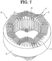
- Fig. 7 only U-phase winding wire 20 as one phase part of the three-phase winding wire is shown.
- the slots 14 are disposed in the circumferential direction of the stator core 12 by the number of 48 (SL1 to SL48). In sixteen of these, the U-phase winding wire is disposed.
- the unit coils are composed of a coil wire element of the same form. Therefore, there has been a problem that it is difficult to make the coil ends small.
- a stator of a rotary machine according to the first invention for solving the above task comprises:
- the stator of the rotary machine according to the second invention for solving the above task is characterized in that the unit coils are arranged by a number of 2n (where n is a natural number of 1 or greater) in the circumferential direction of the stator core, that the distributed winding wire is such that the unit coil at a start of a winding is determined as a first coil and that the unit coil at an end of the winding is determined as a 2nth coil, that two of the slots for receiving the segments constituting the first coil are identical with two of the slots for receiving the segments constituting each of an nth coil, an (n + 1)th coil and the 2nth coil, that other two of the slots for receiving the segments constituting the first coil are identical with two of the slots for receiving the segments constituting each of the a second coil, the (n + 1)th coil, and a (n + 2)th coil, that two of the slots for receiving the segments constituting a (1 + 2i)th coil (where i is a natural number from 1 to (n/2 - 1)
- the stator of the rotary machine according to the third invention for solving the above task is characterized in that the segments include a first segment having a first slot pitch and a second segment having a second slot pitch that is greater than the first slot pitch, that the unit coil is formed by alternately and concentrically arranging the first segment and the second segment in the radial direction, that the slot for receiving a phase terminal side of the first segment constituting the first coil is identical with the slot for receiving a phase terminal side of each of the second segment constituting the nth coil, the first segment constituting the (n + 1)th coil, and the second segment constituting the 2nth coil, that the slot for receiving a phase terminal side of the second segment constituting the first coil is identical with the slot for receiving a phase terminal side of each of the first segment constituting the nth coil, the second segment constituting the (n + 1)th coil, and the first segment constituting the 2nth coil, that the slot for receiving a neutral point side of the first segment constituting the first coil is identical with the slot for receiving a neutral
- the stator of the rotary machine according to the fourth invention for solving the above task is characterized in that unit winding wires of each phase, each unit winding wire being prepared by connecting in series the unit coils by a number of n in the circumferential direction of the stator core, are connected in series.
- the stator of the rotary machine according to the fifth invention for solving the above task is characterized in that unit winding wires of each phase, each unit winding wire being prepared by connecting in series the unit coils by a number of n/2 in the circumferential direction of the stator core, are connected in parallel.
- the stator of the rotary machine according to the sixth invention for solving the above task is characterized in that the segment is formed into a hairpin shape by bending both ends of a single rectangular wire, and both ends are inserted into the slots that are different from each other, and that a tip end portion of one of the segments that is bent to project from the stator core is connected to the tip end portion or a phase terminal or a neutral point of another of the segments.
- the unit coil is formed by alternately and concentrically arranging the segments in the radial direction with a plurality of slot pitches different from each other. This makes it possible to arrange another segment on the inner side in the axial direction of one segment. As compared with conventional unit coils, it is possible to form a unit coil by making the segments dense. This makes it possible to decrease the coil end size. Furthermore, in the case of directly cooling the coil ends with liquid, it becomes possible to sufficiently spread coolant throughout the coil ends due to making the segments dense, thereby improving the cooling effect. Furthermore, it becomes possible to select series wiring or parallel wiring by changing the unit coil's connection relation to be formed by the segment arrangement, even if the segment arrangement is the same. In addition, even in the case of making it into parallel wiring, it is possible to prevent the occurrence of circulating current.
- stator of the electric machine according to one embodiment of the present invention is explained in detail.
- the structure of the stator of the rotary machine according to the present embodiment is generally similar to the above-mentioned rotary machine stator 10 shown in Fig. 7 except each phase winding wire arrangement. Therefore, in the following explanation, members showing functions similar to the above-mentioned members shown in Fig. 7 are designated by the same signs, and the repetitive explanations are omitted.
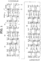
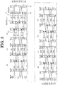
- Fig. 1 and Fig. 2 show a segments 22 arrangement example in the case of constituting U-phase winding by connecting U1 phase and U2 phase as partial windings in series.
- Fig. 1 shows U1 phase arrangement
- Fig. 2 shows U2 phase arrangement.
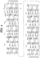
- Fig. 3 and Fig. 4 show a segments 22 arrangement example in the case of constituting U-phase winding by connecting U1 phase to U4 phase as partial windings in parallel.
- Fig. 3 shows an arrangement of U1 phase and U2 phase.
- Fig. 4 shows an arrangement of U3 phase and U4 phase.
- V-phase winding and W-phase winding they have configurations generally similar to U-phase winding except in that their positions in the circumferential direction of the slots 14 for inserting the segments 22 are different. Therefore, their detailed explanations are omitted.
- segment 22 one prepared by forming into a hairpin shape by bending both sides of a single conductor wire element (rectangular wire) is used as segment 22. Both ends of this segment 22 are respectively inserted into different slots 14. A part (hereinafter tip end portion) of segment 22 projecting from the stator core 12 is bent and then connected to the tip end portion of another segment 22 projecting from the stator core 12, U-phase terminal or neutral point N, etc.
- a head side of each segment is shown by a solid line, and a leg side (connection side) of each segment is shown by a broken line.
- the first segment 22 is denoted by S1.
- the first slot 14 is denoted by SL1.
- the first unit coil 21 is denoted by C1.
- Fig. 1 to Fig. 4 white circle indicates the U-phase terminal side of segment 22, and black circle indicates the neutral point N (see Figs. 5 and 6 ) of segment 22. Furthermore, the position of slot 14 at which the segment 22 to be connected to the U-phase terminal is received is dotted, and the position of slot 14 at which the segment 22 to be connected to neutral point N has slash lines.
- the unit coil 21 in the present embodiment is constituted by alternately and concentrically disposing two types of segments 22 (first segment 22A and second segment 22B) in the radial direction.
- First segment 22A is formed in a manner that both ends are inserted into slots 14 with a 5-slots pitch.
- Second segment 22B is formed in a manner that both ends are inserted into slots 14 with a 7-slots pitch.
- the (1 + 2j)th unit coil 21 is composed of five segments 22 of (1+8j)th, (2+8j)th, (3+8j)th, (4+8j)th, and (5+8j)th ones.
- the (1+8j)th segment 22 is the first segment 22A, wherein its U-phase terminal side is received at a position of the conductor number N1 of the (2+12j)th slot 14, and wherein its neutral point side is received at a position of the conductor number N1 of the (7+12j)th slot 14.
- the (2+8j)th segment 22 is the second segment 22B, wherein its U-phase terminal side is received at a position of the conductor number N2 of the (1+12j)th slot 14, and wherein its neutral point side is received at a position of the conductor number N3 of the (8+12j)th slot 14.
- the (3+8j)th segment 22 is the first segment 22A, wherein its U-phase terminal side is received at a position of the conductor number N4 of the (2+12j)th slot 14, and wherein its neutral point side is received at a position of the conductor number N5 of the (7+12j)th slot 14.
- the (4+8j)th segment 22 is the second segment 22B, wherein its U-phase terminal side is received at a position of the conductor number N6 of the (1+12j)th slot 14, and wherein its neutral point side is received at a position of the conductor number N7 of the (8+12j)th slot 14.
- the (5+8j)th segment 22 is the first segment 22A, wherein its U-phase terminal side is received at a position of the conductor number N8 of the (2+12j)th slot 14, and wherein its neutral point side is received at a position of the conductor number N8 of the (7+12j)th slot 14.
- the neutral point side of the (1+8j)th segment 22 and the U-phase terminal side of the (2+8j)th segment are connected, the neutral point side of the (2+8j)th segment 22 and the U-phase terminal side of the (3+8j)th segment are connected, the neutral point side of the (3+8j)th segment 22 and the U-phase terminal side of the (4+8j)th segment are connected, and the neutral point side of the (4+8j)th segment 22 and the U-phase terminal side of the (5+8j)th segment are connected.
- the (2+2j)th unit coil is composed of three segments 22 of the (6+8j)th, the (7+8j)th, and the (8+8j)th ones.
- the (6+8j)th segment 22 is the first segment 22A, wherein its U-phase terminal side is received at a position of the conductor number N7 of the (13+12j)th slot 14, and wherein its neutral point side is received at a position of the conductor number N6 of the (8+12j)th slot 14.
- the (7+8j)th segment 22 is the second segment 22B, wherein its U-phase terminal side is received at a position of the conductor number N5 of the (14+12j)th slot 14, and wherein its neutral point side is received at a position of the conductor number N4 of the (7+12j)th slot 14.
- the (8+8j)th segment 22 is the first segment 22A, wherein its U-phase terminal side is received at a position of the conductor number N3 of the (13+12j)th slot 14, and wherein its neutral point side is received at a position of the conductor number N2 of the (8+12j)th slot 14.
- the 30 th segment 22 is the first segment 22A, wherein its U-phase terminal side is received at a position of the conductor number N7 of the first slot 14, and wherein its neutral point side is received at a position of the conductor number N6 of the 44th slot 14.
- the 31 st segment 22 is the second segment 22B, wherein its U-phase terminal side is received at a position of the conductor number N5 of the second slot 14, and wherein its neutral point side is received at a position of the conductor number N4 of the 43 rd slot 14.
- the 32 nd segment 22 is the first segment 22A, wherein its U-phase terminal side is received at a position of the conductor number N3 of the first slot 14, and wherein its neutral point side is received at a position of the conductor number N2 of the 44th slot 14.
- the (9 + 2j)th unit coil 21 is composed of five segments 22 of (33+8j)th, (34+8j)th, (35+8j)th, (36+8j)th, and (37+8j)th ones.
- the (33+8j)th segment 22 is the second segment 22B, wherein its U-phase terminal side is received at a position of the conductor number N1 of the (1+12j)th slot 14, and wherein its neutral point side is received at a position of the conductor number N1 of the (8+12j)th slot 14.
- the (34+8j)th segment 22 is the first segment 22A, wherein its U-phase terminal side is received at a position of the conductor number N2 of the (2+12j)th slot 14, and wherein its neutral point side is received at a position of the conductor number N3 of the (7+12j)th slot 14.
- the (35+8j)th segment 22 is the second segment 22B, wherein its U-phase terminal side is received at a position of the conductor number N4 of the (1+12j)th slot 14, and wherein its neutral point side is received at a position of the conductor number N5 of the (8+12j)th slot 14.
- the (36+8j)th segment 22 is the first segment 22A, wherein its U-phase terminal side is received at a position of the conductor number N6 of the (2+12j)th slot 14, and wherein its neutral point side is received at a position of the conductor number N7 of the (7+12j)th slot 14.
- the (37+8j)th segment 22 is the second segment 22B, wherein its U-phase terminal side is received at a position of the conductor number N8 of the (1+12j)th slot 14, and wherein its neutral point side is received at a position of the conductor number N8 of the (8+12j)th slot 14.
- the (10+2j)th unit coil is composed of three segments 22 of the (38+8j)th, the (39+8j)th, and the (40+8j)th ones.
- the (38+8j)th segment 22 is the second segment 22B, wherein its U-phase terminal side is received at a position of the conductor number N7 of the (14+12j)th slot 14, and wherein its neutral point side is received at a position of the conductor number N6 of the (7+12j)th slot 14.
- the (39+8j)th segment 22 is the first segment 22A, wherein its U-phase terminal side is received at a position of the conductor number N5 of the (13+12j)th slot 14, and wherein its neutral point side is received at a position of the conductor number N4 of the (8+12j)th slot 14.
- the (40+8j)th segment 22 is the second segment 22B, wherein its U-phase terminal side is received at a position of the conductor number N3 of the (14+12j)th slot 14, and wherein its neutral point side is received at a position of the conductor number N2 of the (7+12j)th slot 14.
- the 62 nd segment 22 is the second segment 22B, wherein its U-phase terminal side is received at a position of the conductor number N7 of the second slot 14, and wherein its neutral point side is received at a position of the conductor number N6 of the 43 rd slot 14.
- the 63 rd segment 22 is the first segment 22A, wherein its U-phase terminal side is received at a position of the conductor number N5 of the first slot 14, and wherein its neutral point side is received at a position of the conductor number N4 of the 44th slot 14.
- the 64 th segment 22 is the second segment 22B, wherein its U-phase terminal side is received at a position of the conductor number N3 of the second slot 14, and wherein its neutral point side is received at a position of the conductor number N2 of the 43 rd slot 14.
- the segments 22 (22A and 22B) having two slot pitches are concentrically disposed at slots 14. This results in a condition in which the segments 22 constituting one unit coil 21 are received in four slots 14.
- the slot 14 for receiving each phase's terminal side (hereinafter, phase terminal side) of the first segments 22A constituting the first unit coil 21 is the same as the slot 14 for receiving the phase terminal sides of the second segment 22B of the nth unit coil 21 that is adjacent to one side of the first unit coil, of the first segments 22A of the (n+1)th coil 21, and of the second segments 22B of the 2nth unit coil 21 that is adjacent to one side of the (n+1)th unit coil 21.
- the slot 14 for receiving the phase terminal sides of the second segments 22B constituting the first unit coil 21 is the same as the slot 14 for receiving the phase terminal sides of the first segments 22A of the nth unit coil that is adjacent to one side of the first unit coil 21, of the second segments 22B of the (n+1)th unit coil, and of the first segment 22A of the 2nth unit coil 21 that is adjacent to one side of the (n+1)th unit coil 21.
- the slot 14 for receiving the neutral point sides of the first segments 22A constituting the first unit coil 21 is the same as the slot 14 for receiving the neutral point sides of the second segment 22B of the second unit coil 21 that is adjacent to the other side of the first unit coil 21, of the first segments 22A of the (n+1)th unit coil 21, and of the second segments 22B of the (n+2)th unit coil 21 that is adjacent to the other side of the (n+1)th unit coil 21.
- the slot 14 for receiving the neutral sides of the second segments 22B constituting the first unit coil 21 is the same as the slot 14 for receiving the neutral point sides of the first segments 22A of the second unit coil 21 that is adjacent to the other side of the first unit coil 21, of the second segments 22B of the (n+1)th unit coil 21, and of the first segment 22A of the (n+2)th unit coil 21 that is adjacent to the other side of the (n+1)th unit coil 21.
- the slot 14 for receiving the each phase's terminal sides (hereinafter phase terminal sides) of the first segments 22A constituting the (1+2i)th unit coil 21 (wherein i is a natural number from 1 to (n/2 - 1)) is the same as the slot 14 for receiving the phase terminal sides of the second segment 22B of the 2ith unit coil 21 that is adjacent to one side of the (1+2i)th unit coil, of the first segments 22A of the (n+1+2i)th unit coil 21, and of the second segments 22B of the (n+2i)th unit coil 21 that is adjacent to one side of the (n+1+2i)th unit coil.
- the slot 14 for receiving the phase terminal sides of the second segments 22B constituting the (1+2i)th unit coil 21 is the same as the slot 14 for receiving the phase terminal sides of the first segments 22A of the 2ith unit coil 21 that is adjacent to one side of the (1+2i)th unit coil 21, of the second segments 22B of the (n+1+2i)th unit coil 21, and of the first segment 22A of the (n+2i)th unit coil 21 that is adjacent to one side of the (n+1+2i)th unit coil.
- the slot 14 for receiving the neutral point sides of the first segments 22A constituting the (1+2i)th unit coil is the same as the slot 14 for receiving the neutral point sides of the second segment 22B of the (2+2i)th unit coil 21 that is adjacent to the other side of the (1+2i)th unit coil, of the first segments 22A of the (n+1+2i)th unit coil 21, and of the second segments 22B of the (n+2+2i)th unit coil 21 that is adjacent to the other side of the (n+1+2i)th unit coil 21.
- the slot 14 for receiving the neutral point sides of the second segments 22B constituting the (1+2i)th unit coil 21 is the same as the slot for receiving the neutral point sides of the first segments 22A of the (2+2i)th unit coil 21 that is adjacent to the other side of the (1+2i)th unit coil 21, of the second segments 22B of the (n+1+2i)th unit coil 21, and of the first segment 22A of the (n+2+2i)th unit coil 21 that is adjacent to the other side of the (n+1+2i)th unit coil 21.
- U1 phase winding wire is prepared by connecting the first to eighth unit coils 21 in series that are prepared by respectively connecting the neutral point sides of the fifth, eighth, 13 th , 16 th , 21 st , 24 th , 29 th segments 22 and the U-phase terminal sides of the 6 th , 9 th , 14 th , 17 th , 22 nd , 25 th , and 30 th segments.
- U2 phase winding wire is prepared by connecting the ninth to 16 th unit coils 21 in series that are prepared by respectively connecting the neutral point sides of the 37 th , 40 th , 45 th , 48 th , 53 rd , 56 th , and 61 st segments 22 and the U-phase terminal sides of the 38 th , 41 st , 46 th , 49 th , 54 th , 57 th , and 62 nd segments 22.
- U-phase winding wire in which U1 phase winding wire and U2 phase winding wire are connected in series, by connecting a leg portion on the neutral point side of the 32 nd segment 22 and a leg portion on the U-phase terminal side of the 33 rd segment 22.
- a V-phase winding wire is prepared by connecting V1 phase winding wire and V2 phase winding wire in series
- a W-phase winding wire is prepared by connecting W1 phase winding wire and W2 phase winding wire. It is possible to form the stator coil into a series winding wire structure by a Y connection of the U-phase winding wire, the V-phase winding wire, and the W-phase winding wire.
- U1 phase winding wire is prepared by connecting the first to fourth unit coils 21 in series that are prepared by respectively connecting the neutral point sides of the fifth, eighth, and 13 th segments 22 and the U-phase terminal sides of the 6 th , 9 th , and 14 th segments.
- U2 phase winding wire is prepared by connecting the fifth to eighth unit coils 21 in series that are prepared by respectively connecting the neutral point sides of the 21 st , 24 th , and 29 th segments 22 and the U-phase terminal sides of the 22 nd , 25 th , and 30 th segments 22.
- U3 phase winding wire is prepared by connecting the ninth to 12 th unit coils 21 in series that are prepared by respectively connecting the neutral point sides of the 37 th , 40 th , and 45 th segments 22 and the U-phase terminal sides of the 38 th , 41 st , and 46th segments.
- U4 phase winding wire is prepared by connecting the 13 th to 16 th unit coils 21 in series that are prepared by respectively connecting the neutral point sides of the 53 rd , 56 th , and 61 st segments 22 and the U-phase terminal sides of the 54 th , 57 th , and 62 nd segments 22.
- U-phase winding wire in which U1 to U4 phase winding wires are connected in parallel, by connecting a leg portion on the U-phase terminal side of the first segment 22, a leg portion on the U-phase terminal side of the 17 th segment 22, a leg portion on the U-phase terminal side of the 33 rd segment 22, and a leg portion on the U-phase terminal side of the 49 th segment 22, and by connecting a leg portion on the neutral point N side of the 16 th segment 22, a leg portion on the neutral point N side of the 32 nd segment 22, a leg portion on the neutral point N side of the 48 th segment 22, and a leg portion on the neutral point N side of the 64 th segment 22.
- a V-phase winding wire is prepared by connecting V1 to V4 phase winding wires in parallel
- a W-phase winding wire is prepared by connecting W1 to W4 phase winding wires in parallel. It is possible to form the stator coil into a parallel winding wire structure by a Y connection of the U-phase winding wire, the V-phase winding wire, and the W-phase winding wire.
- the unit coil 21 is formed by alternately and concentrically arranging the segments 22 with a plurality of slot pitches that are different from each other. This makes it possible to arrange the first segment 22A on the inner side in the axial direction of the second segment 22B. As compared with conventional unit coils, it is possible to form the unit coil 21 by making the segments 22 dense. This makes it possible to decrease the coil end size. Furthermore, in the case of directly cooling the coil ends with liquid, it becomes possible to sufficiently spread coolant throughout the coil ends due to making the segments 22 dense, thereby improving the cooling effect.
- the rotary machine's stator according to the present embodiment it becomes possible by the rotary machine's stator according to the present embodiment to select (switch) series wiring or parallel wiring by changing the connection relation of each unit coil 21, even if the arrangement of the segments 22 is the same. Therefore, it becomes possible to easily change terminal voltage of the rotary machine, thereby improving convenience. Furthermore, even in the case of making it into a parallel wiring structure, it is possible to prevent the occurrence of circulating current.
- the present invention is not limited to the above-mentioned embodiment. According to need, it is possible to set the number of unit coils 21 for constituting the winding wire of each phase, the number of the segments 22 for constituting the unit coil 21, the slot pitch of the segment 22, etc. to the extent not deviating from the gist of the present invention.
Landscapes
- Engineering & Computer Science (AREA)
- Power Engineering (AREA)
- Windings For Motors And Generators (AREA)
- Iron Core Of Rotating Electric Machines (AREA)
Abstract
Description
- The present invention relates to a stator of a rotary machine.
- The following
Patent Publication 1 discloses a rotary machine for high-voltage vehicles, with a sequentially joined-segment stator coil, which enables to adjacently position a plurality of the same phase slots and to achieve the voltage increase of the rotary machine by increasing the number of turns while suppressing accompanying adverse effects, by providing a plurality of the same phase, adjacent slots and providing special segments and special U-phase segments, which are different from normal segments (9 slot pitch) as segments and have slot pitches different from each other. - Furthermore, as shown in
Fig. 7 , the followingPatent Publication 2 discloses that, in a rotaryelectric machine stator 10 composed of astator core 12 prepared by stacking a plurality of annular electromagnetic steel plates and three-phase winding wires 20 to be wound about thestator core 12, a winding wire of each phase is composed by combining 16unit coils 21 each being formed by winding a coil wire element into a generally hexagonal shape, and that, inslots 14 as grooves which are opened on the annular inner peripheral side of thestator core 12, extend in the radial direction, and are arranged by a plural number in the circumferential direction, thesecond unit coil 21 is disposed to be right adjacent to thefirst unit coil 21, and then the third, the fourth, the fifth, ..., the 14th and the 15th are disposed to be adjacent in sequence to make two rounds in the circumferential direction to result in the 16thunit coil 21. In this composition, thefirst unit coil 21 and theninth unit coil 21 are partly overlapped to be displaced by one slot. Similarly, suppose that the coil number is i, the ith coil and the (i+1)th coil are partly overlappingly disposed to be displaced by one slot. - In
Fig. 7 , onlyU-phase winding wire 20 as one phase part of the three-phase winding wire is shown. In an example shown inFig. 7 , theslots 14 are disposed in the circumferential direction of thestator core 12 by the number of 48 (SL1 to SL48). In sixteen of these, the U-phase winding wire is disposed. -
- Patent Publication 1:
JP Patent Application Publication 2004-23808 - Patent Publication 2:
JP Patent Application Publication 2012-16195 - Here, in the segment disposition of the above-mentioned
Patent Publication 1, in the case of changing the terminal voltage, it becomes necessary to reconsider the winding wire arrangement. Thus, there has been a problem that the terminal voltage cannot be changed easily. - Furthermore, in the above-mentioned
Patent Publication 2, the unit coils are composed of a coil wire element of the same form. Therefore, there has been a problem that it is difficult to make the coil ends small. - In view of this, it is an object of the present invention to provide a rotary machine stator in which the coil ends can be made smaller and which is adaptable to a plurality of voltage specifications by changing the connection method without changing the winding wire disposition.
- A stator of a rotary machine according to the first invention for solving the above task comprises:
- a stator core having a plurality of slots provided along a circumferential direction;
- segments that are composed of rectangular wires and received in the slots; and
- a distributed winding wire that is formed by arranging unit coils, each of which is made up of a plurality of the segments disposed along a radial direction, in the circumferential direction of the stator core,
- wherein the unit coil is formed by connecting the segments that are alternately and concentrically arranged in the radial direction with a plurality of slot pitches that are different from each other.
- The stator of the rotary machine according to the second invention for solving the above task is characterized in that the unit coils are arranged by a number of 2n (where n is a natural number of 1 or greater) in the circumferential direction of the stator core,
that the distributed winding wire is such that the unit coil at a start of a winding is determined as a first coil and that the unit coil at an end of the winding is determined as a 2nth coil,
that two of the slots for receiving the segments constituting the first coil are identical with two of the slots for receiving the segments constituting each of an nth coil, an (n + 1)th coil and the 2nth coil,
that other two of the slots for receiving the segments constituting the first coil are identical with two of the slots for receiving the segments constituting each of the a second coil, the (n + 1)th coil, and a (n + 2)th coil,
that two of the slots for receiving the segments constituting a (1 + 2i)th coil (where i is a natural number from 1 to (n/2 - 1)) are identical with two of the slots for receiving the segments constituting each of a 2ith coil, an (n + 2i)th coil, and an (n + 1 + 2i)th coil,
that other two of the slots for receiving the segments constituting the (1 + 2i)th coil are identical with two of the slots for receiving the segments constituting each of a (2 + 2i)th coil, the (n + 1 + 2i)th coil, and an (n + 2 + 2i)th coil. - The stator of the rotary machine according to the third invention for solving the above task is characterized in that the segments include a first segment having a first slot pitch and a second segment having a second slot pitch that is greater than the first slot pitch,
that the unit coil is formed by alternately and concentrically arranging the first segment and the second segment in the radial direction,
that the slot for receiving a phase terminal side of the first segment constituting the first coil is identical with the slot for receiving a phase terminal side of each of the second segment constituting the nth coil, the first segment constituting the (n + 1)th coil, and the second segment constituting the 2nth coil,
that the slot for receiving a phase terminal side of the second segment constituting the first coil is identical with the slot for receiving a phase terminal side of each of the first segment constituting the nth coil, the second segment constituting the (n + 1)th coil, and the first segment constituting the 2nth coil,
that the slot for receiving a neutral point side of the first segment constituting the first coil is identical with the slot for receiving a neutral point side of each of the second segment constituting the second coil, the first segment constituting the (n + 1)th coil, and the second segment constituting the (n + 2)th coil,
that the slot for receiving a neutral point side of the second segment constituting the first coil is identical with the slot for receiving a neutral point side of each of the first segment constituting the second coil, the second segment constituting the (n + 1)th coil, and the first segment constituting the (n + 2)th coil,
that the slot for receiving a phase terminal side of the first segment constituting the (1 + 2i)th coil is identical with the slot for receiving a phase terminal side of each of the second segment constituting the 2ith coil, the first segment constituting the (n + 1 + 2i)th coil, and the second segment constituting the (n + 2i)th coil,
that the slot for receiving a terminal phase side of the second segment constituting the (1 + 2i)th coil is identical with the slot for receiving a phase terminal side of each of the first segment constituting the 2ith coil, the second segment constituting the (n + 1 + 2i)th coil, and the first segment constituting the (n + 2i)th coil,
that the slot for receiving a neutral point side of the first segment constituting the (1 + 2i)th coil is identical with the slot for receiving a neutral point side of each of the second segment constituting the (2 + 2i)th coil, the first segment constituting the (n + 1 + 2i)th coil, and the second segment constituting the (n + 2 + 2i)th coil,
that the slot for receiving a neutral point side of the second segment constituting the (1 + 2i)th coil is identical with the slot for receiving a neutral point side of each of the first segment constituting the (2 + 2i)th coil, the second segment constituting the (n + 1 + 2i)th coil, and the first segment constituting the (n + 2 + 2i)th coil. - The stator of the rotary machine according to the fourth invention for solving the above task is characterized in that unit winding wires of each phase, each unit winding wire being prepared by connecting in series the unit coils by a number of n in the circumferential direction of the stator core, are connected in series.
- The stator of the rotary machine according to the fifth invention for solving the above task is characterized in that unit winding wires of each phase, each unit winding wire being prepared by connecting in series the unit coils by a number of n/2 in the circumferential direction of the stator core, are connected in parallel.
- The stator of the rotary machine according to the sixth invention for solving the above task is characterized in that the segment is formed into a hairpin shape by bending both ends of a single rectangular wire, and both ends are inserted into the slots that are different from each other, and
that a tip end portion of one of the segments that is bent to project from the stator core is connected to the tip end portion or a phase terminal or a neutral point of another of the segments. - In accordance with the stator of the rotary machine according to the present invention, the unit coil is formed by alternately and concentrically arranging the segments in the radial direction with a plurality of slot pitches different from each other. This makes it possible to arrange another segment on the inner side in the axial direction of one segment. As compared with conventional unit coils, it is possible to form a unit coil by making the segments dense. This makes it possible to decrease the coil end size. Furthermore, in the case of directly cooling the coil ends with liquid, it becomes possible to sufficiently spread coolant throughout the coil ends due to making the segments dense, thereby improving the cooling effect. Furthermore, it becomes possible to select series wiring or parallel wiring by changing the unit coil's connection relation to be formed by the segment arrangement, even if the segment arrangement is the same. In addition, even in the case of making it into parallel wiring, it is possible to prevent the occurrence of circulating current.
-
-
Fig. 1 is an explanatory view showing a U1 phase segments arrangement example in the case of connecting a partial winding wire in series in the stator of the rotary machine according to an embodiment of the present invention; -
Fig. 2 is an explanatory view showing a U2 phase segments arrangement example in the case of connecting a partial winding wire in series in the stator of the rotary machine according to an embodiment of the present invention; -
Fig. 3 is an explanatory view showing U1 phase and U2 phase segments arrangement example in the case of connecting a partial winding wire in parallel in the stator of the rotary machine according to an embodiment of the present invention; -
Fig. 4 is an explanatory view showing U3 phase and U4 phase segments arrangement example in the case of connecting a partial winding wire in parallel in the stator of the rotary machine according to an embodiment of the present invention; -
Fig. 5 is a connection diagram in the case of connecting the partial winding wire of each phase in series; -
Fig. 6 is a connection diagram in the case of connecting the partial winding wire of each phase in parallel; and -
Fig. 7 is a view showing a condition in which one phase distributed winding coil is wound in a conventional rotary machine stator. - In the following, the stator of the rotary machine according to the present invention is explained with reference to the drawings.
- Using
Fig. 1 to Fig. 6 , the stator of the electric machine according to one embodiment of the present invention is explained in detail. The structure of the stator of the rotary machine according to the present embodiment is generally similar to the above-mentionedrotary machine stator 10 shown inFig. 7 except each phase winding wire arrangement. Therefore, in the following explanation, members showing functions similar to the above-mentioned members shown inFig. 7 are designated by the same signs, and the repetitive explanations are omitted. -
Fig. 1 andFig. 2 show asegments 22 arrangement example in the case of constituting U-phase winding by connecting U1 phase and U2 phase as partial windings in series.Fig. 1 shows U1 phase arrangement, andFig. 2 shows U2 phase arrangement. Furthermore,Fig. 3 andFig. 4 show asegments 22 arrangement example in the case of constituting U-phase winding by connecting U1 phase to U4 phase as partial windings in parallel.Fig. 3 shows an arrangement of U1 phase and U2 phase.Fig. 4 shows an arrangement of U3 phase and U4 phase. With respect to V-phase winding and W-phase winding, they have configurations generally similar to U-phase winding except in that their positions in the circumferential direction of theslots 14 for inserting thesegments 22 are different. Therefore, their detailed explanations are omitted. - In the present embodiment, one prepared by forming into a hairpin shape by bending both sides of a single conductor wire element (rectangular wire) is used as
segment 22. Both ends of thissegment 22 are respectively inserted intodifferent slots 14. A part (hereinafter tip end portion) ofsegment 22 projecting from thestator core 12 is bent and then connected to the tip end portion of anothersegment 22 projecting from thestator core 12, U-phase terminal or neutral point N, etc. - In
Fig. 1 to Fig. 4 , a head side of each segment is shown by a solid line, and a leg side (connection side) of each segment is shown by a broken line. InFig. 1 to Fig. 4 , Sa is a symbol for identifyingsegment 22, and a = 1, 2, ..., 64 in the order to be connected. For example, thefirst segment 22 is denoted by S1. Furthermore, SLb is a symbol for identifyingslot 14, and b = 1, 2, ..., 48 (seeFig. 7 ) in the order along the circumferential direction. For example, thefirst slot 14 is denoted by SL1. Furthermore, Nc is a symbol (conductor number) for identifying the position where thesegment 22 is received (inserted) inslot 14, and c = 1, 2, ..., 8 in the order from the radial outside. Furthermore, Cd is a symbol for identifyingunit coil 21 composed of a plurality ofsegments 22 that are concentrically wound, and d = 1, 2, ..., 16 in the order to be connected. For example, thefirst unit coil 21 is denoted by C1.Unit coil 21 is disposed by the number of 2n (where n is a natural number of 1 or greater, and n = 8 in the present embodiment) in the circumferential direction of thestator core 12. - Furthermore, in
Fig. 1 to Fig. 4 , white circle indicates the U-phase terminal side ofsegment 22, and black circle indicates the neutral point N (seeFigs. 5 and 6 ) ofsegment 22. Furthermore, the position ofslot 14 at which thesegment 22 to be connected to the U-phase terminal is received is dotted, and the position ofslot 14 at which thesegment 22 to be connected to neutral point N has slash lines. - As shown in
Fig. 1 to Fig. 4 , theunit coil 21 in the present embodiment is constituted by alternately and concentrically disposing two types of segments 22 (first segment 22A andsecond segment 22B) in the radial direction.First segment 22A is formed in a manner that both ends are inserted intoslots 14 with a 5-slots pitch.Second segment 22B is formed in a manner that both ends are inserted intoslots 14 with a 7-slots pitch. - More specifically, as shown in
Fig. 1 andFig. 3 , suppose that j is a natural number from 0 to (n/2 - 1) (in the present embodiment, j = 0, 1, 2, 3), the (1 + 2j)th unit coil 21 is composed of fivesegments 22 of (1+8j)th, (2+8j)th, (3+8j)th, (4+8j)th, and (5+8j)th ones. - The (1+8j)
th segment 22 is thefirst segment 22A, wherein its U-phase terminal side is received at a position of the conductor number N1 of the (2+12j)th slot 14, and wherein its neutral point side is received at a position of the conductor number N1 of the (7+12j)th slot 14. The (2+8j)th segment 22 is thesecond segment 22B, wherein its U-phase terminal side is received at a position of the conductor number N2 of the (1+12j)th slot 14, and wherein its neutral point side is received at a position of the conductor number N3 of the (8+12j)th slot 14. The (3+8j)th segment 22 is thefirst segment 22A, wherein its U-phase terminal side is received at a position of the conductor number N4 of the (2+12j)th slot 14, and wherein its neutral point side is received at a position of the conductor number N5 of the (7+12j)th slot 14. The (4+8j)th segment 22 is thesecond segment 22B, wherein its U-phase terminal side is received at a position of the conductor number N6 of the (1+12j)th slot 14, and wherein its neutral point side is received at a position of the conductor number N7 of the (8+12j)th slot 14. The (5+8j)th segment 22 is thefirst segment 22A, wherein its U-phase terminal side is received at a position of the conductor number N8 of the (2+12j)th slot 14, and wherein its neutral point side is received at a position of the conductor number N8 of the (7+12j)th slot 14. - In the (1+2j)
th unit coil 21, as shown by broken lines in the drawing, the neutral point side of the (1+8j)th segment 22 and the U-phase terminal side of the (2+8j)th segment are connected, the neutral point side of the (2+8j)th segment 22 and the U-phase terminal side of the (3+8j)th segment are connected, the neutral point side of the (3+8j)th segment 22 and the U-phase terminal side of the (4+8j)th segment are connected, and the neutral point side of the (4+8j)th segment 22 and the U-phase terminal side of the (5+8j)th segment are connected. - Furthermore, the (2+2j)th unit coil is composed of three
segments 22 of the (6+8j)th, the (7+8j)th, and the (8+8j)th ones. - The (6+8j)
th segment 22 is thefirst segment 22A, wherein its U-phase terminal side is received at a position of the conductor number N7 of the (13+12j)th slot 14, and wherein its neutral point side is received at a position of the conductor number N6 of the (8+12j)th slot 14. The (7+8j)th segment 22 is thesecond segment 22B, wherein its U-phase terminal side is received at a position of the conductor number N5 of the (14+12j)th slot 14, and wherein its neutral point side is received at a position of the conductor number N4 of the (7+12j)th slot 14. The (8+8j)th segment 22 is thefirst segment 22A, wherein its U-phase terminal side is received at a position of the conductor number N3 of the (13+12j)th slot 14, and wherein its neutral point side is received at a position of the conductor number N2 of the (8+12j)th slot 14. - In the (2+2j)
th unit coil 21, as shown by broken lines in the drawing, the neutral point side of the (6+8j)th segment 22 and the U-phase terminal side of the (7+8j)th segment 22 are connected, and the neutral point side of the (7+8j)th segment 22 and the U-phase terminal side of the (8+8j)th segment 22 are connected. - However, in the
eighth unit coil 21, the 30thsegment 22 is thefirst segment 22A, wherein its U-phase terminal side is received at a position of the conductor number N7 of thefirst slot 14, and wherein its neutral point side is received at a position of the conductor number N6 of the44th slot 14. The 31stsegment 22 is thesecond segment 22B, wherein its U-phase terminal side is received at a position of the conductor number N5 of thesecond slot 14, and wherein its neutral point side is received at a position of the conductor number N4 of the 43rdslot 14. The 32ndsegment 22 is thefirst segment 22A, wherein its U-phase terminal side is received at a position of the conductor number N3 of thefirst slot 14, and wherein its neutral point side is received at a position of the conductor number N2 of the44th slot 14. - Furthermore, as shown in
Fig. 2 andFig. 4 , suppose that j = 0, 1, 2, ..., (n/2 - 1) (in the present embodiment, j = 0, 1, 2, 3), the (9 + 2j)th unit coil 21 is composed of fivesegments 22 of (33+8j)th, (34+8j)th, (35+8j)th, (36+8j)th, and (37+8j)th ones. - The (33+8j)
th segment 22 is thesecond segment 22B, wherein its U-phase terminal side is received at a position of the conductor number N1 of the (1+12j)th slot 14, and wherein its neutral point side is received at a position of the conductor number N1 of the (8+12j)th slot 14. The (34+8j)th segment 22 is thefirst segment 22A, wherein its U-phase terminal side is received at a position of the conductor number N2 of the (2+12j)th slot 14, and wherein its neutral point side is received at a position of the conductor number N3 of the (7+12j)th slot 14. The (35+8j)th segment 22 is thesecond segment 22B, wherein its U-phase terminal side is received at a position of the conductor number N4 of the (1+12j)th slot 14, and wherein its neutral point side is received at a position of the conductor number N5 of the (8+12j)th slot 14. The (36+8j)th segment 22 is thefirst segment 22A, wherein its U-phase terminal side is received at a position of the conductor number N6 of the (2+12j)th slot 14, and wherein its neutral point side is received at a position of the conductor number N7 of the (7+12j)th slot 14. The (37+8j)th segment 22 is thesecond segment 22B, wherein its U-phase terminal side is received at a position of the conductor number N8 of the (1+12j)th slot 14, and wherein its neutral point side is received at a position of the conductor number N8 of the (8+12j)th slot 14. - Furthermore, the (10+2j)th unit coil is composed of three
segments 22 of the (38+8j)th, the (39+8j)th, and the (40+8j)th ones. - The (38+8j)
th segment 22 is thesecond segment 22B, wherein its U-phase terminal side is received at a position of the conductor number N7 of the (14+12j)th slot 14, and wherein its neutral point side is received at a position of the conductor number N6 of the (7+12j)th slot 14. The (39+8j)th segment 22 is thefirst segment 22A, wherein its U-phase terminal side is received at a position of the conductor number N5 of the (13+12j)th slot 14, and wherein its neutral point side is received at a position of the conductor number N4 of the (8+12j)th slot 14. The (40+8j)th segment 22 is thesecond segment 22B, wherein its U-phase terminal side is received at a position of the conductor number N3 of the (14+12j)th slot 14, and wherein its neutral point side is received at a position of the conductor number N2 of the (7+12j)th slot 14. - However, in the
16th unit coil 21, the 62ndsegment 22 is thesecond segment 22B, wherein its U-phase terminal side is received at a position of the conductor number N7 of thesecond slot 14, and wherein its neutral point side is received at a position of the conductor number N6 of the 43rdslot 14. The 63rdsegment 22 is thefirst segment 22A, wherein its U-phase terminal side is received at a position of the conductor number N5 of thefirst slot 14, and wherein its neutral point side is received at a position of the conductor number N4 of the44th slot 14. The 64thsegment 22 is thesecond segment 22B, wherein its U-phase terminal side is received at a position of the conductor number N3 of thesecond slot 14, and wherein its neutral point side is received at a position of the conductor number N2 of the 43rdslot 14. - That is, in the present embodiment, in each
unit coil 21, the segments 22 (22A and 22B) having two slot pitches are concentrically disposed atslots 14. This results in a condition in which thesegments 22 constituting oneunit coil 21 are received in fourslots 14. - Then, the
slot 14 for receiving each phase's terminal side (hereinafter, phase terminal side) of thefirst segments 22A constituting thefirst unit coil 21 is the same as theslot 14 for receiving the phase terminal sides of thesecond segment 22B of thenth unit coil 21 that is adjacent to one side of the first unit coil, of thefirst segments 22A of the (n+1)th coil 21, and of thesecond segments 22B of the2nth unit coil 21 that is adjacent to one side of the (n+1)th unit coil 21. - Furthermore, the
slot 14 for receiving the phase terminal sides of thesecond segments 22B constituting thefirst unit coil 21 is the same as theslot 14 for receiving the phase terminal sides of thefirst segments 22A of the nth unit coil that is adjacent to one side of thefirst unit coil 21, of thesecond segments 22B of the (n+1)th unit coil, and of thefirst segment 22A of the2nth unit coil 21 that is adjacent to one side of the (n+1)th unit coil 21. - Furthermore, the
slot 14 for receiving the neutral point sides of thefirst segments 22A constituting thefirst unit coil 21 is the same as theslot 14 for receiving the neutral point sides of thesecond segment 22B of thesecond unit coil 21 that is adjacent to the other side of thefirst unit coil 21, of thefirst segments 22A of the (n+1)th unit coil 21, and of thesecond segments 22B of the (n+2)th unit coil 21 that is adjacent to the other side of the (n+1)th unit coil 21. - Furthermore, the
slot 14 for receiving the neutral sides of thesecond segments 22B constituting thefirst unit coil 21 is the same as theslot 14 for receiving the neutral point sides of thefirst segments 22A of thesecond unit coil 21 that is adjacent to the other side of thefirst unit coil 21, of thesecond segments 22B of the (n+1)th unit coil 21, and of thefirst segment 22A of the (n+2)th unit coil 21 that is adjacent to the other side of the (n+1)th unit coil 21. - Furthermore, the
slot 14 for receiving the each phase's terminal sides (hereinafter phase terminal sides) of thefirst segments 22A constituting the (1+2i)th unit coil 21 (wherein i is a natural number from 1 to (n/2 - 1)) is the same as theslot 14 for receiving the phase terminal sides of thesecond segment 22B of the2ith unit coil 21 that is adjacent to one side of the (1+2i)th unit coil, of thefirst segments 22A of the (n+1+2i)th unit coil 21, and of thesecond segments 22B of the (n+2i)th unit coil 21 that is adjacent to one side of the (n+1+2i)th unit coil. - Furthermore, the
slot 14 for receiving the phase terminal sides of thesecond segments 22B constituting the (1+2i)th unit coil 21 is the same as theslot 14 for receiving the phase terminal sides of thefirst segments 22A of the2ith unit coil 21 that is adjacent to one side of the (1+2i)th unit coil 21, of thesecond segments 22B of the (n+1+2i)th unit coil 21, and of thefirst segment 22A of the (n+2i)th unit coil 21 that is adjacent to one side of the (n+1+2i)th unit coil. - Furthermore, the
slot 14 for receiving the neutral point sides of thefirst segments 22A constituting the (1+2i)th unit coil is the same as theslot 14 for receiving the neutral point sides of thesecond segment 22B of the (2+2i)th unit coil 21 that is adjacent to the other side of the (1+2i)th unit coil, of thefirst segments 22A of the (n+1+2i)th unit coil 21, and of thesecond segments 22B of the (n+2+2i)th unit coil 21 that is adjacent to the other side of the (n+1+2i)th unit coil 21. - Furthermore, the
slot 14 for receiving the neutral point sides of thesecond segments 22B constituting the (1+2i)th unit coil 21 is the same as the slot for receiving the neutral point sides of thefirst segments 22A of the (2+2i)th unit coil 21 that is adjacent to the other side of the (1+2i)th unit coil 21, of thesecond segments 22B of the (n+1+2i)th unit coil 21, and of thefirst segment 22A of the (n+2+2i)th unit coil 21 that is adjacent to the other side of the (n+1+2i)th unit coil 21. - In such rotary machine's stator of the present embodiment, as shown in
Fig. 1 andFig. 2 , U1 phase winding wire is prepared by connecting the first to eighth unit coils 21 in series that are prepared by respectively connecting the neutral point sides of the fifth, eighth, 13th, 16th, 21st, 24th, 29thsegments 22 and the U-phase terminal sides of the 6th, 9th, 14th, 17th, 22nd, 25th, and 30th segments. U2 phase winding wire is prepared by connecting the ninth to 16th unit coils 21 in series that are prepared by respectively connecting the neutral point sides of the 37th, 40th, 45th, 48th, 53rd, 56th, and 61stsegments 22 and the U-phase terminal sides of the 38th, 41st, 46th, 49th, 54th, 57th, and 62ndsegments 22. It is possible to prepare a U-phase winding wire, in which U1 phase winding wire and U2 phase winding wire are connected in series, by connecting a leg portion on the neutral point side of the 32ndsegment 22 and a leg portion on the U-phase terminal side of the 33rdsegment 22. - Similarly, as shown in
Fig. 5 , a V-phase winding wire is prepared by connecting V1 phase winding wire and V2 phase winding wire in series, and a W-phase winding wire is prepared by connecting W1 phase winding wire and W2 phase winding wire. It is possible to form the stator coil into a series winding wire structure by a Y connection of the U-phase winding wire, the V-phase winding wire, and the W-phase winding wire. - Furthermore, as shown in
Fig. 3 andFig. 4 , U1 phase winding wire is prepared by connecting the first to fourth unit coils 21 in series that are prepared by respectively connecting the neutral point sides of the fifth, eighth, and 13thsegments 22 and the U-phase terminal sides of the 6th, 9th, and 14th segments. U2 phase winding wire is prepared by connecting the fifth to eighth unit coils 21 in series that are prepared by respectively connecting the neutral point sides of the 21st, 24th, and 29thsegments 22 and the U-phase terminal sides of the 22nd, 25th, and 30thsegments 22. U3 phase winding wire is prepared by connecting the ninth to 12th unit coils 21 in series that are prepared by respectively connecting the neutral point sides of the 37th, 40th, and 45thsegments 22 and the U-phase terminal sides of the 38th, 41st, and 46th segments. U4 phase winding wire is prepared by connecting the 13th to 16th unit coils 21 in series that are prepared by respectively connecting the neutral point sides of the 53rd, 56th, and 61stsegments 22 and the U-phase terminal sides of the 54th, 57th, and 62ndsegments 22. It is possible to prepare a U-phase winding wire, in which U1 to U4 phase winding wires are connected in parallel, by connecting a leg portion on the U-phase terminal side of thefirst segment 22, a leg portion on the U-phase terminal side of the 17thsegment 22, a leg portion on the U-phase terminal side of the 33rdsegment 22, and a leg portion on the U-phase terminal side of the 49thsegment 22, and by connecting a leg portion on the neutral point N side of the 16thsegment 22, a leg portion on the neutral point N side of the 32ndsegment 22, a leg portion on the neutral point N side of the 48thsegment 22, and a leg portion on the neutral point N side of the 64thsegment 22. - Similarly, as shown in
Fig. 6 , a V-phase winding wire is prepared by connecting V1 to V4 phase winding wires in parallel, and a W-phase winding wire is prepared by connecting W1 to W4 phase winding wires in parallel. It is possible to form the stator coil into a parallel winding wire structure by a Y connection of the U-phase winding wire, the V-phase winding wire, and the W-phase winding wire. - According to the above-configured rotary machine's stator according to the present embodiment, the
unit coil 21 is formed by alternately and concentrically arranging thesegments 22 with a plurality of slot pitches that are different from each other. This makes it possible to arrange thefirst segment 22A on the inner side in the axial direction of thesecond segment 22B. As compared with conventional unit coils, it is possible to form theunit coil 21 by making thesegments 22 dense. This makes it possible to decrease the coil end size. Furthermore, in the case of directly cooling the coil ends with liquid, it becomes possible to sufficiently spread coolant throughout the coil ends due to making thesegments 22 dense, thereby improving the cooling effect. - Furthermore, it becomes possible by the rotary machine's stator according to the present embodiment to select (switch) series wiring or parallel wiring by changing the connection relation of each
unit coil 21, even if the arrangement of thesegments 22 is the same. Therefore, it becomes possible to easily change terminal voltage of the rotary machine, thereby improving convenience. Furthermore, even in the case of making it into a parallel wiring structure, it is possible to prevent the occurrence of circulating current. - The present invention is not limited to the above-mentioned embodiment. According to need, it is possible to set the number of unit coils 21 for constituting the winding wire of each phase, the number of the
segments 22 for constituting theunit coil 21, the slot pitch of thesegment 22, etc. to the extent not deviating from the gist of the present invention. -
- 10:
- rotary machine stator
- 12:
- stator core
- 14:
- slot
- 20:
- U-phase winding wire
- 21:
- unit coil
- 22:
- segment
- 22A:
- first segment
- 22B:
- second segment
Claims (6)
- A stator of a rotary machine, comprising:a stator core having a plurality of slots provided along a circumferential direction;segments that are composed of rectangular wires and received in the slots; anda distributed winding wire that is formed by arranging unit coils, each of which is made up of a plurality of the segments disposed along a radial direction, in the circumferential direction of the stator core,wherein the unit coil is formed by connecting the segments that are alternately and concentrically arranged in the radial direction with a plurality of slot pitches that are different from each other.
- The stator of the rotary machine as claimed in claim 1, wherein the unit coils are arranged by a number of 2n (where n is a natural number of 1 or greater) in the circumferential direction of the stator core,
wherein the distributed winding wire is such that the unit coil at a start of a winding is determined as a first coil and that the unit coil at an end of the winding is determined as a 2nth coil,
wherein two of the slots for receiving the segments constituting the first coil are identical with two of the slots for receiving the segments constituting each of an nth coil, an (n + 1)th coil and the 2nth coil,
wherein other two of the slots for receiving the segments constituting the first coil are identical with two of the slots for receiving the segments constituting each of the a second coil, the (n + 1)th coil, and a (n + 2)th coil,
wherein two of the slots for receiving the segments constituting a (1 + 2i)th coil (where i is a natural number from 1 to (n/2 - 1)) are identical with two of the slots for receiving the segments constituting each of a 2ith coil, an (n + 2i)th coil, and an (n + 1 + 2i)th coil,
wherein other two of the slots for receiving the segments constituting the (1 + 2i)th coil are identical with two of the slots for receiving the segments constituting each of a (2 + 2i)th coil, the (n + 1 + 2i)th coil, and an (n + 2 + 2i)th coil. - The stator of the rotary machine as claimed in claim 2, wherein the segments include a first segment having a first slot pitch and a second segment having a second slot pitch that is greater than the first slot pitch,
wherein the unit coil is formed by alternately and concentrically arranging the first segment and the second segment in the radial direction,
wherein the slot for receiving a phase terminal side of the first segment constituting the first coil is identical with the slot for receiving a phase terminal side of each of the second segment constituting the nth coil, the first segment constituting the (n + 1)th coil, and the second segment constituting the 2nth coil,
wherein the slot for receiving a phase terminal side of the second segment constituting the first coil is identical with the slot for receiving a phase terminal side of each of the first segment constituting the nth coil, the second segment constituting the (n + 1)th coil, and the first segment constituting the 2nth coil,
wherein the slot for receiving a neutral point side of the first segment constituting the first coil is identical with the slot for receiving a neutral point side of each of the second segment constituting the second coil, the first segment constituting the (n + 1)th coil, and the second segment constituting the (n + 2)th coil,
wherein the slot for receiving a neutral point side of the second segment constituting the first coil is identical with the slot for receiving a neutral point side of each of the first segment constituting the second coil, the second segment constituting the (n + 1)th coil, and the first segment constituting the (n + 2)th coil,
wherein the slot for receiving a phase terminal side of the first segment constituting the (1 + 2i)th coil is identical with the slot for receiving a phase terminal side of each of the second segment constituting the 2ith coil, the first segment constituting the (n + 1 + 2i)th coil, and the second segment constituting the (n + 2i)th coil,
wherein the slot for receiving a terminal phase side of the second segment constituting the (1 + 2i)th coil is identical with the slot for receiving a phase terminal side of each of the first segment constituting the 2ith coil, the second segment constituting the (n + 1 + 2i)th coil, and the first segment constituting the (n + 2i)th coil,
wherein the slot for receiving a neutral point side of the first segment constituting the (1 + 2i)th coil is identical with the slot for receiving a neutral point side of each of the second segment constituting the (2 + 2i)th coil, the first segment constituting the (n + 1 + 2i)th coil, and the second segment constituting the (n + 2 + 2i)th coil,
wherein the slot for receiving a neutral point side of the second segment constituting the (1 + 2i)th coil is identical with the slot for receiving a neutral point side of each of the first segment constituting the (2 + 2i)th coil, the second segment constituting the (n + 1 + 2i)th coil, and the first segment constituting the (n + 2 + 2i)th coil. - The stator of the rotary machine as claimed in any one of claim 1 to claim 3, wherein unit winding wires of each phase, each unit winding wire being prepared by connecting in series the unit coils by a number of n in the circumferential direction of the stator core, are connected in series.
- The stator of the rotary machine as claimed in any one of claim 1 to claim 3, wherein unit winding wires of each phase, each unit winding wire being prepared by connecting in series the unit coils by a number of n/2 in the circumferential direction of the stator core, are connected in parallel.
- The stator of the rotary machine as claimed in any one of claim 1 to claim 5, wherein the segment is formed into a hairpin shape by bending both ends of a single rectangular wire, and both ends are inserted into the slots that are different from each other,
wherein a tip end portion of one of the segments that is bent to project from the stator core is connected to the tip end portion or a phase terminal or a neutral point of another of the segments.
Applications Claiming Priority (2)
| Application Number | Priority Date | Filing Date | Title |
|---|---|---|---|
| JP2017247241A JP6508318B1 (en) | 2017-12-25 | 2017-12-25 | Stator of rotating machine |
| PCT/JP2018/042406 WO2019130893A1 (en) | 2017-12-25 | 2018-11-16 | Stator of rotary machine |
Publications (3)
| Publication Number | Publication Date |
|---|---|
| EP3731378A1 true EP3731378A1 (en) | 2020-10-28 |
| EP3731378A4 EP3731378A4 (en) | 2021-01-20 |
| EP3731378B1 EP3731378B1 (en) | 2022-06-08 |
Family
ID=66429908
Family Applications (1)
| Application Number | Title | Priority Date | Filing Date |
|---|---|---|---|
| EP18894629.7A Active EP3731378B1 (en) | 2017-12-25 | 2018-11-16 | Stator for rotary machine |
Country Status (5)
| Country | Link |
|---|---|
| US (1) | US11056944B2 (en) |
| EP (1) | EP3731378B1 (en) |
| JP (1) | JP6508318B1 (en) |
| CN (1) | CN111527671B (en) |
| WO (1) | WO2019130893A1 (en) |
Cited By (1)
| Publication number | Priority date | Publication date | Assignee | Title |
|---|---|---|---|---|
| DE102020213647A1 (en) | 2020-10-29 | 2022-05-05 | Valeo Siemens Eautomotive Germany Gmbh | Stator for an electric machine and electric machine |
Families Citing this family (3)
| Publication number | Priority date | Publication date | Assignee | Title |
|---|---|---|---|---|
| EP3696950B1 (en) * | 2017-12-14 | 2022-08-24 | Aisin Corporation | Stator |
| JP7128702B2 (en) * | 2018-09-25 | 2022-08-31 | 株式会社Soken | Rotating electric machine |
| DE102022203671A1 (en) | 2022-04-12 | 2023-10-12 | Volkswagen Aktiengesellschaft | Stator for a three-phase electric machine, electric machine and motor vehicle with electric machine |
Family Cites Families (29)
| Publication number | Priority date | Publication date | Assignee | Title |
|---|---|---|---|---|
| JP3494729B2 (en) * | 1995-01-24 | 2004-02-09 | 株式会社東芝 | Three-phase armature winding |
| JP3515283B2 (en) * | 1995-08-18 | 2004-04-05 | 株式会社東芝 | Armature winding of rotating electric machine and method of manufacturing the same |
| JP3745707B2 (en) * | 2002-06-12 | 2006-02-15 | 株式会社デンソー | Rotating electrical machine for high-voltage vehicles having segmented sequential joining type stator coil |
| DE10326095A1 (en) * | 2002-06-12 | 2004-04-15 | Denso Corp., Kariya | Coil of sequentially connected segments for a rotating electrical machine |
| JP2007151393A (en) * | 2007-01-16 | 2007-06-14 | Denso Corp | Tandem rotary electric machine for vehicles |
| JP4715934B2 (en) * | 2009-02-20 | 2011-07-06 | 株式会社デンソー | 5-phase motor |
| JP5691266B2 (en) * | 2010-07-01 | 2015-04-01 | トヨタ自動車株式会社 | Rotating electric machine stator |
| JP5541585B2 (en) * | 2010-12-28 | 2014-07-09 | 株式会社デンソー | Rotating electric machine |
| JP2012200101A (en) * | 2011-03-23 | 2012-10-18 | Toyota Motor Corp | Rotating electric machine stator and method of manufacturing rotating electric machine stator |
| JP5703918B2 (en) * | 2011-04-08 | 2015-04-22 | トヨタ自動車株式会社 | Rotating electric machine stator |
| JP5502913B2 (en) * | 2012-01-23 | 2014-05-28 | 三菱電機株式会社 | Rotating electric machine |
| US9531227B2 (en) * | 2012-03-29 | 2016-12-27 | Honda Motor Co., Ltd. | Stator structure for rotary electric machine |
| JP5791805B2 (en) * | 2012-07-06 | 2015-10-07 | 三菱電機株式会社 | Rotating electric machine and manufacturing method thereof |
| DE112013003663B4 (en) * | 2012-07-26 | 2025-01-23 | Mitsubishi Electric Corporation | Electric rotary machine |
| JP5757282B2 (en) * | 2012-11-07 | 2015-07-29 | 株式会社デンソー | Stator and rotating electric machine |
| US9887599B2 (en) * | 2013-04-02 | 2018-02-06 | Mitsubishi Electric Corporation | Stator for rotary electric machine |
| JP5855318B2 (en) * | 2013-05-17 | 2016-02-09 | 三菱電機株式会社 | Stator manufacturing method |
| DE112014005444B4 (en) * | 2013-11-29 | 2025-07-31 | Mitsubishi Electric Corporation | Armature for an electrical machine |
| WO2015107679A1 (en) * | 2014-01-17 | 2015-07-23 | 三菱電機株式会社 | Rotating electric machine |
| WO2015145696A1 (en) * | 2014-03-27 | 2015-10-01 | 株式会社小松製作所 | Stator and dynamo-electric machine containing same |
| DE112015001564T5 (en) * | 2014-03-31 | 2017-02-16 | Honda Motor Co., Ltd. | Stator for electric rotating machine |
| WO2015162643A1 (en) * | 2014-04-24 | 2015-10-29 | 三菱電機株式会社 | Stator of rotary electrical machine and rotary electrical machine using such stator |
| JP6156268B2 (en) * | 2014-06-27 | 2017-07-05 | 株式会社デンソー | Rotating electric machine stator |
| JP6409367B2 (en) * | 2014-06-30 | 2018-10-24 | アイシン精機株式会社 | Rotating electric machine and manufacturing method thereof |
| CN107078578B (en) * | 2014-09-22 | 2019-04-30 | 三菱电机株式会社 | The stator of rotating electric machine |
| JP6235504B2 (en) * | 2015-02-17 | 2017-11-22 | ファナック株式会社 | Radial gap type motor with distributed winding and winding arrangement method thereof |
| JP6610249B2 (en) * | 2015-12-25 | 2019-11-27 | アイシン精機株式会社 | Rotating electric machine and manufacturing method thereof |
| JP6173507B1 (en) * | 2016-03-04 | 2017-08-02 | 三菱電機株式会社 | Stator for rotating electric machine and method for manufacturing the same |
| DE102018207231A1 (en) * | 2018-05-09 | 2019-11-14 | Volkswagen Aktiengesellschaft | Stator for an electric machine, electric machine and manufacturing method for a stator for an electric machine |
-
2017
- 2017-12-25 JP JP2017247241A patent/JP6508318B1/en active Active
-
2018
- 2018-11-16 US US16/954,264 patent/US11056944B2/en active Active
- 2018-11-16 CN CN201880083740.2A patent/CN111527671B/en active Active
- 2018-11-16 WO PCT/JP2018/042406 patent/WO2019130893A1/en not_active Ceased
- 2018-11-16 EP EP18894629.7A patent/EP3731378B1/en active Active
Cited By (1)
| Publication number | Priority date | Publication date | Assignee | Title |
|---|---|---|---|---|
| DE102020213647A1 (en) | 2020-10-29 | 2022-05-05 | Valeo Siemens Eautomotive Germany Gmbh | Stator for an electric machine and electric machine |
Also Published As
| Publication number | Publication date |
|---|---|
| EP3731378B1 (en) | 2022-06-08 |
| EP3731378A4 (en) | 2021-01-20 |
| JP6508318B1 (en) | 2019-05-08 |
| US20200395805A1 (en) | 2020-12-17 |
| CN111527671A (en) | 2020-08-11 |
| US11056944B2 (en) | 2021-07-06 |
| JP2019115180A (en) | 2019-07-11 |
| CN111527671B (en) | 2021-07-16 |
| WO2019130893A1 (en) | 2019-07-04 |
Similar Documents
| Publication | Publication Date | Title |
|---|---|---|
| US11418070B2 (en) | Stator and rotary electric machine | |
| EP2730009B1 (en) | Stator for an electric machine | |
| US11056944B2 (en) | Stator of rotary machine | |
| CN111478477A (en) | Motor stator and motor | |
| CN111478478A (en) | Motor stator and motor | |
| CN112436619A (en) | Motor stator and motor | |
| CN111555505A (en) | Motor stator and motor | |
| CN112332564A (en) | A motor stator and motor | |
| CN112821598A (en) | Motor stator and motor | |
| CN111478480A (en) | Motor stator and motor | |
| CN112260428B (en) | Motor stator and motor | |
| CN213585303U (en) | Motor stator and motor | |
| CN112531932A (en) | Motor stator and motor | |
| CN112332565A (en) | Motor stator and motor | |
| CN213637231U (en) | A motor stator and motor | |
| CN112260426B (en) | Motor stator and motor | |
| CN213585304U (en) | Motor stator and motor | |
| CN211908498U (en) | Motor stator and motor | |
| CN210327195U (en) | Motor winding and motor stator | |
| US20260135427A1 (en) | Modular hairpin winding and stator structure | |
| EP4742505A1 (en) | Modular hairpin winding and stator structure | |
| CN213547206U (en) | Motor stator and motor | |
| CN214124964U (en) | Motor stator and motor | |
| CN214281060U (en) | Motor stator and motor | |
| CN214626538U (en) | Motor stator and motor |
Legal Events
| Date | Code | Title | Description |
|---|---|---|---|
| STAA | Information on the status of an ep patent application or granted ep patent |
Free format text: STATUS: THE INTERNATIONAL PUBLICATION HAS BEEN MADE |
|
| PUAI | Public reference made under article 153(3) epc to a published international application that has entered the european phase |
Free format text: ORIGINAL CODE: 0009012 |
|
| STAA | Information on the status of an ep patent application or granted ep patent |
Free format text: STATUS: REQUEST FOR EXAMINATION WAS MADE |
|
| 17P | Request for examination filed |
Effective date: 20200721 |
|
| AK | Designated contracting states |
Kind code of ref document: A1 Designated state(s): AL AT BE BG CH CY CZ DE DK EE ES FI FR GB GR HR HU IE IS IT LI LT LU LV MC MK MT NL NO PL PT RO RS SE SI SK SM TR |
|
| AX | Request for extension of the european patent |
Extension state: BA ME |
|
| A4 | Supplementary search report drawn up and despatched |
Effective date: 20201217 |
|
| RIC1 | Information provided on ipc code assigned before grant |
Ipc: H02K 3/28 20060101AFI20201211BHEP Ipc: H02K 3/04 20060101ALI20201211BHEP Ipc: H02K 3/12 20060101ALN20201211BHEP Ipc: H02K 1/16 20060101ALN20201211BHEP Ipc: H02K 1/12 20060101ALI20201211BHEP |
|
| DAV | Request for validation of the european patent (deleted) | ||
| DAX | Request for extension of the european patent (deleted) | ||
| STAA | Information on the status of an ep patent application or granted ep patent |
Free format text: STATUS: EXAMINATION IS IN PROGRESS |
|
| 17Q | First examination report despatched |
Effective date: 20210507 |
|
| GRAP | Despatch of communication of intention to grant a patent |
Free format text: ORIGINAL CODE: EPIDOSNIGR1 |
|
| STAA | Information on the status of an ep patent application or granted ep patent |
Free format text: STATUS: GRANT OF PATENT IS INTENDED |
|
| RIC1 | Information provided on ipc code assigned before grant |
Ipc: H02K 3/12 20060101ALN20211202BHEP Ipc: H02K 1/16 20060101ALN20211202BHEP Ipc: H02K 3/04 20060101ALI20211202BHEP Ipc: H02K 1/12 20060101ALI20211202BHEP Ipc: H02K 3/28 20060101AFI20211202BHEP |
|
| INTG | Intention to grant announced |
Effective date: 20211220 |
|
| GRAS | Grant fee paid |
Free format text: ORIGINAL CODE: EPIDOSNIGR3 |
|
| GRAA | (expected) grant |
Free format text: ORIGINAL CODE: 0009210 |
|
| STAA | Information on the status of an ep patent application or granted ep patent |
Free format text: STATUS: THE PATENT HAS BEEN GRANTED |
|
| AK | Designated contracting states |
Kind code of ref document: B1 Designated state(s): AL AT BE BG CH CY CZ DE DK EE ES FI FR GB GR HR HU IE IS IT LI LT LU LV MC MK MT NL NO PL PT RO RS SE SI SK SM TR |
|
| REG | Reference to a national code |
Ref country code: AT Ref legal event code: REF Ref document number: 1497602 Country of ref document: AT Kind code of ref document: T Effective date: 20220615 Ref country code: CH Ref legal event code: EP |
|
| REG | Reference to a national code |
Ref country code: DE Ref legal event code: R096 Ref document number: 602018036643 Country of ref document: DE |
|
| REG | Reference to a national code |
Ref country code: IE Ref legal event code: FG4D |
|
| REG | Reference to a national code |
Ref country code: LT Ref legal event code: MG9D |
|
| REG | Reference to a national code |
Ref country code: NL Ref legal event code: MP Effective date: 20220608 |
|
| PG25 | Lapsed in a contracting state [announced via postgrant information from national office to epo] |
Ref country code: SE Free format text: LAPSE BECAUSE OF FAILURE TO SUBMIT A TRANSLATION OF THE DESCRIPTION OR TO PAY THE FEE WITHIN THE PRESCRIBED TIME-LIMIT Effective date: 20220608 Ref country code: NO Free format text: LAPSE BECAUSE OF FAILURE TO SUBMIT A TRANSLATION OF THE DESCRIPTION OR TO PAY THE FEE WITHIN THE PRESCRIBED TIME-LIMIT Effective date: 20220908 Ref country code: LT Free format text: LAPSE BECAUSE OF FAILURE TO SUBMIT A TRANSLATION OF THE DESCRIPTION OR TO PAY THE FEE WITHIN THE PRESCRIBED TIME-LIMIT Effective date: 20220608 Ref country code: HR Free format text: LAPSE BECAUSE OF FAILURE TO SUBMIT A TRANSLATION OF THE DESCRIPTION OR TO PAY THE FEE WITHIN THE PRESCRIBED TIME-LIMIT Effective date: 20220608 Ref country code: GR Free format text: LAPSE BECAUSE OF FAILURE TO SUBMIT A TRANSLATION OF THE DESCRIPTION OR TO PAY THE FEE WITHIN THE PRESCRIBED TIME-LIMIT Effective date: 20220909 Ref country code: FI Free format text: LAPSE BECAUSE OF FAILURE TO SUBMIT A TRANSLATION OF THE DESCRIPTION OR TO PAY THE FEE WITHIN THE PRESCRIBED TIME-LIMIT Effective date: 20220608 Ref country code: BG Free format text: LAPSE BECAUSE OF FAILURE TO SUBMIT A TRANSLATION OF THE DESCRIPTION OR TO PAY THE FEE WITHIN THE PRESCRIBED TIME-LIMIT Effective date: 20220908 |
|
| REG | Reference to a national code |
Ref country code: AT Ref legal event code: MK05 Ref document number: 1497602 Country of ref document: AT Kind code of ref document: T Effective date: 20220608 |
|
| PG25 | Lapsed in a contracting state [announced via postgrant information from national office to epo] |
Ref country code: RS Free format text: LAPSE BECAUSE OF FAILURE TO SUBMIT A TRANSLATION OF THE DESCRIPTION OR TO PAY THE FEE WITHIN THE PRESCRIBED TIME-LIMIT Effective date: 20220608 Ref country code: LV Free format text: LAPSE BECAUSE OF FAILURE TO SUBMIT A TRANSLATION OF THE DESCRIPTION OR TO PAY THE FEE WITHIN THE PRESCRIBED TIME-LIMIT Effective date: 20220608 |
|
| PG25 | Lapsed in a contracting state [announced via postgrant information from national office to epo] |
Ref country code: NL Free format text: LAPSE BECAUSE OF FAILURE TO SUBMIT A TRANSLATION OF THE DESCRIPTION OR TO PAY THE FEE WITHIN THE PRESCRIBED TIME-LIMIT Effective date: 20220608 |
|
| PG25 | Lapsed in a contracting state [announced via postgrant information from national office to epo] |
Ref country code: SM Free format text: LAPSE BECAUSE OF FAILURE TO SUBMIT A TRANSLATION OF THE DESCRIPTION OR TO PAY THE FEE WITHIN THE PRESCRIBED TIME-LIMIT Effective date: 20220608 Ref country code: SK Free format text: LAPSE BECAUSE OF FAILURE TO SUBMIT A TRANSLATION OF THE DESCRIPTION OR TO PAY THE FEE WITHIN THE PRESCRIBED TIME-LIMIT Effective date: 20220608 Ref country code: RO Free format text: LAPSE BECAUSE OF FAILURE TO SUBMIT A TRANSLATION OF THE DESCRIPTION OR TO PAY THE FEE WITHIN THE PRESCRIBED TIME-LIMIT Effective date: 20220608 Ref country code: PT Free format text: LAPSE BECAUSE OF FAILURE TO SUBMIT A TRANSLATION OF THE DESCRIPTION OR TO PAY THE FEE WITHIN THE PRESCRIBED TIME-LIMIT Effective date: 20221010 Ref country code: ES Free format text: LAPSE BECAUSE OF FAILURE TO SUBMIT A TRANSLATION OF THE DESCRIPTION OR TO PAY THE FEE WITHIN THE PRESCRIBED TIME-LIMIT Effective date: 20220608 Ref country code: EE Free format text: LAPSE BECAUSE OF FAILURE TO SUBMIT A TRANSLATION OF THE DESCRIPTION OR TO PAY THE FEE WITHIN THE PRESCRIBED TIME-LIMIT Effective date: 20220608 Ref country code: CZ Free format text: LAPSE BECAUSE OF FAILURE TO SUBMIT A TRANSLATION OF THE DESCRIPTION OR TO PAY THE FEE WITHIN THE PRESCRIBED TIME-LIMIT Effective date: 20220608 Ref country code: AT Free format text: LAPSE BECAUSE OF FAILURE TO SUBMIT A TRANSLATION OF THE DESCRIPTION OR TO PAY THE FEE WITHIN THE PRESCRIBED TIME-LIMIT Effective date: 20220608 |
|
| PG25 | Lapsed in a contracting state [announced via postgrant information from national office to epo] |
Ref country code: PL Free format text: LAPSE BECAUSE OF FAILURE TO SUBMIT A TRANSLATION OF THE DESCRIPTION OR TO PAY THE FEE WITHIN THE PRESCRIBED TIME-LIMIT Effective date: 20220608 Ref country code: IS Free format text: LAPSE BECAUSE OF FAILURE TO SUBMIT A TRANSLATION OF THE DESCRIPTION OR TO PAY THE FEE WITHIN THE PRESCRIBED TIME-LIMIT Effective date: 20221008 |
|
| REG | Reference to a national code |
Ref country code: DE Ref legal event code: R097 Ref document number: 602018036643 Country of ref document: DE |
|
| PG25 | Lapsed in a contracting state [announced via postgrant information from national office to epo] |
Ref country code: AL Free format text: LAPSE BECAUSE OF FAILURE TO SUBMIT A TRANSLATION OF THE DESCRIPTION OR TO PAY THE FEE WITHIN THE PRESCRIBED TIME-LIMIT Effective date: 20220608 |
|
| PLBE | No opposition filed within time limit |
Free format text: ORIGINAL CODE: 0009261 |
|
| STAA | Information on the status of an ep patent application or granted ep patent |
Free format text: STATUS: NO OPPOSITION FILED WITHIN TIME LIMIT |
|
| PG25 | Lapsed in a contracting state [announced via postgrant information from national office to epo] |
Ref country code: DK Free format text: LAPSE BECAUSE OF FAILURE TO SUBMIT A TRANSLATION OF THE DESCRIPTION OR TO PAY THE FEE WITHIN THE PRESCRIBED TIME-LIMIT Effective date: 20220608 |
|
| 26N | No opposition filed |
Effective date: 20230310 |
|
| PG25 | Lapsed in a contracting state [announced via postgrant information from national office to epo] |
Ref country code: SI Free format text: LAPSE BECAUSE OF FAILURE TO SUBMIT A TRANSLATION OF THE DESCRIPTION OR TO PAY THE FEE WITHIN THE PRESCRIBED TIME-LIMIT Effective date: 20220608 |
|
| PG25 | Lapsed in a contracting state [announced via postgrant information from national office to epo] |
Ref country code: MC Free format text: LAPSE BECAUSE OF FAILURE TO SUBMIT A TRANSLATION OF THE DESCRIPTION OR TO PAY THE FEE WITHIN THE PRESCRIBED TIME-LIMIT Effective date: 20220608 |
|
| REG | Reference to a national code |
Ref country code: CH Ref legal event code: PL |
|
| GBPC | Gb: european patent ceased through non-payment of renewal fee |
Effective date: 20221116 |
|
| REG | Reference to a national code |
Ref country code: BE Ref legal event code: MM Effective date: 20221130 |
|
| PG25 | Lapsed in a contracting state [announced via postgrant information from national office to epo] |
Ref country code: LI Free format text: LAPSE BECAUSE OF NON-PAYMENT OF DUE FEES Effective date: 20221130 Ref country code: CH Free format text: LAPSE BECAUSE OF NON-PAYMENT OF DUE FEES Effective date: 20221130 |
|
| PG25 | Lapsed in a contracting state [announced via postgrant information from national office to epo] |
Ref country code: LU Free format text: LAPSE BECAUSE OF NON-PAYMENT OF DUE FEES Effective date: 20221116 |
|
| PG25 | Lapsed in a contracting state [announced via postgrant information from national office to epo] |
Ref country code: IE Free format text: LAPSE BECAUSE OF NON-PAYMENT OF DUE FEES Effective date: 20221116 Ref country code: GB Free format text: LAPSE BECAUSE OF NON-PAYMENT OF DUE FEES Effective date: 20221116 |
|
| PG25 | Lapsed in a contracting state [announced via postgrant information from national office to epo] |
Ref country code: BE Free format text: LAPSE BECAUSE OF NON-PAYMENT OF DUE FEES Effective date: 20221130 |
|
| PG25 | Lapsed in a contracting state [announced via postgrant information from national office to epo] |
Ref country code: IT Free format text: LAPSE BECAUSE OF FAILURE TO SUBMIT A TRANSLATION OF THE DESCRIPTION OR TO PAY THE FEE WITHIN THE PRESCRIBED TIME-LIMIT Effective date: 20220608 |
|
| PG25 | Lapsed in a contracting state [announced via postgrant information from national office to epo] |
Ref country code: CY Free format text: LAPSE BECAUSE OF FAILURE TO SUBMIT A TRANSLATION OF THE DESCRIPTION OR TO PAY THE FEE WITHIN THE PRESCRIBED TIME-LIMIT Effective date: 20220608 |
|
| PG25 | Lapsed in a contracting state [announced via postgrant information from national office to epo] |
Ref country code: MK Free format text: LAPSE BECAUSE OF FAILURE TO SUBMIT A TRANSLATION OF THE DESCRIPTION OR TO PAY THE FEE WITHIN THE PRESCRIBED TIME-LIMIT Effective date: 20220608 Ref country code: HU Free format text: LAPSE BECAUSE OF FAILURE TO SUBMIT A TRANSLATION OF THE DESCRIPTION OR TO PAY THE FEE WITHIN THE PRESCRIBED TIME-LIMIT; INVALID AB INITIO Effective date: 20181116 |
|
| PG25 | Lapsed in a contracting state [announced via postgrant information from national office to epo] |
Ref country code: MT Free format text: LAPSE BECAUSE OF FAILURE TO SUBMIT A TRANSLATION OF THE DESCRIPTION OR TO PAY THE FEE WITHIN THE PRESCRIBED TIME-LIMIT Effective date: 20220608 |
|
| PG25 | Lapsed in a contracting state [announced via postgrant information from national office to epo] |
Ref country code: BG Free format text: LAPSE BECAUSE OF FAILURE TO SUBMIT A TRANSLATION OF THE DESCRIPTION OR TO PAY THE FEE WITHIN THE PRESCRIBED TIME-LIMIT Effective date: 20220608 |
|
| PG25 | Lapsed in a contracting state [announced via postgrant information from national office to epo] |
Ref country code: BG Free format text: LAPSE BECAUSE OF FAILURE TO SUBMIT A TRANSLATION OF THE DESCRIPTION OR TO PAY THE FEE WITHIN THE PRESCRIBED TIME-LIMIT Effective date: 20220608 |
|
| PG25 | Lapsed in a contracting state [announced via postgrant information from national office to epo] |
Ref country code: TR Free format text: LAPSE BECAUSE OF FAILURE TO SUBMIT A TRANSLATION OF THE DESCRIPTION OR TO PAY THE FEE WITHIN THE PRESCRIBED TIME-LIMIT Effective date: 20220608 |
|
| PGFP | Annual fee paid to national office [announced via postgrant information from national office to epo] |
Ref country code: DE Payment date: 20251119 Year of fee payment: 8 |
|
| PGFP | Annual fee paid to national office [announced via postgrant information from national office to epo] |
Ref country code: FR Payment date: 20251126 Year of fee payment: 8 |