EP3731365A1 - Wireless charging system, wireless charging device and wireless powered device - Google Patents
Wireless charging system, wireless charging device and wireless powered device Download PDFInfo
- Publication number
- EP3731365A1 EP3731365A1 EP19219211.0A EP19219211A EP3731365A1 EP 3731365 A1 EP3731365 A1 EP 3731365A1 EP 19219211 A EP19219211 A EP 19219211A EP 3731365 A1 EP3731365 A1 EP 3731365A1
- Authority
- EP
- European Patent Office
- Prior art keywords
- wireless
- light
- powered device
- wireless powered
- wireless charging
- Prior art date
- Legal status (The legal status is an assumption and is not a legal conclusion. Google has not performed a legal analysis and makes no representation as to the accuracy of the status listed.)
- Pending
Links
Images





Classifications
-
- H—ELECTRICITY
- H02—GENERATION; CONVERSION OR DISTRIBUTION OF ELECTRIC POWER
- H02J—ELECTRIC POWER NETWORKS; CIRCUIT ARRANGEMENTS OR SYSTEMS FOR SUPPLYING OR DISTRIBUTING ELECTRIC POWER; SYSTEMS FOR STORING ELECTRIC ENERGY
- H02J50/00—Circuit arrangements or systems for wireless supply or distribution of electric power
- H02J50/30—Circuit arrangements or systems for wireless supply or distribution of electric power using light, e.g. lasers
-
- H—ELECTRICITY
- H02—GENERATION; CONVERSION OR DISTRIBUTION OF ELECTRIC POWER
- H02J—ELECTRIC POWER NETWORKS; CIRCUIT ARRANGEMENTS OR SYSTEMS FOR SUPPLYING OR DISTRIBUTING ELECTRIC POWER; SYSTEMS FOR STORING ELECTRIC ENERGY
- H02J50/00—Circuit arrangements or systems for wireless supply or distribution of electric power
- H02J50/005—Mechanical details of housing or structure aiming to accommodate the power transfer means, e.g. mechanical integration of coils, antennas or transducers into emitting or receiving devices
-
- H—ELECTRICITY
- H02—GENERATION; CONVERSION OR DISTRIBUTION OF ELECTRIC POWER
- H02J—ELECTRIC POWER NETWORKS; CIRCUIT ARRANGEMENTS OR SYSTEMS FOR SUPPLYING OR DISTRIBUTING ELECTRIC POWER; SYSTEMS FOR STORING ELECTRIC ENERGY
- H02J50/00—Circuit arrangements or systems for wireless supply or distribution of electric power
- H02J50/40—Circuit arrangements or systems for wireless supply or distribution of electric power using two or more transmitting or receiving devices
-
- H—ELECTRICITY
- H02—GENERATION; CONVERSION OR DISTRIBUTION OF ELECTRIC POWER
- H02J—ELECTRIC POWER NETWORKS; CIRCUIT ARRANGEMENTS OR SYSTEMS FOR SUPPLYING OR DISTRIBUTING ELECTRIC POWER; SYSTEMS FOR STORING ELECTRIC ENERGY
- H02J50/00—Circuit arrangements or systems for wireless supply or distribution of electric power
- H02J50/80—Circuit arrangements or systems for wireless supply or distribution of electric power involving the exchange of data, concerning supply or distribution of electric power, between transmitting devices and receiving devices
-
- H—ELECTRICITY
- H02—GENERATION; CONVERSION OR DISTRIBUTION OF ELECTRIC POWER
- H02J—ELECTRIC POWER NETWORKS; CIRCUIT ARRANGEMENTS OR SYSTEMS FOR SUPPLYING OR DISTRIBUTING ELECTRIC POWER; SYSTEMS FOR STORING ELECTRIC ENERGY
- H02J7/00—Circuit arrangements for charging or discharging batteries or for supplying loads from batteries
-
- H—ELECTRICITY
- H02—GENERATION; CONVERSION OR DISTRIBUTION OF ELECTRIC POWER
- H02J—ELECTRIC POWER NETWORKS; CIRCUIT ARRANGEMENTS OR SYSTEMS FOR SUPPLYING OR DISTRIBUTING ELECTRIC POWER; SYSTEMS FOR STORING ELECTRIC ENERGY
- H02J7/00—Circuit arrangements for charging or discharging batteries or for supplying loads from batteries
- H02J7/70—Circuit arrangements for charging or discharging batteries or for supplying loads from batteries characterised by the mechanical construction
-
- H—ELECTRICITY
- H02—GENERATION; CONVERSION OR DISTRIBUTION OF ELECTRIC POWER
- H02S—GENERATION OF ELECTRIC POWER BY CONVERSION OF INFRARED RADIATION, VISIBLE LIGHT OR ULTRAVIOLET LIGHT, e.g. USING PHOTOVOLTAIC [PV] MODULES
- H02S10/00—PV power plants; Combinations of PV energy systems with other systems for the generation of electric power
-
- H—ELECTRICITY
- H02—GENERATION; CONVERSION OR DISTRIBUTION OF ELECTRIC POWER
- H02S—GENERATION OF ELECTRIC POWER BY CONVERSION OF INFRARED RADIATION, VISIBLE LIGHT OR ULTRAVIOLET LIGHT, e.g. USING PHOTOVOLTAIC [PV] MODULES
- H02S40/00—Components or accessories in combination with PV modules, not provided for in groups H02S10/00 - H02S30/00
- H02S40/30—Electrical components
- H02S40/38—Energy storage means, e.g. batteries, structurally associated with PV modules
-
- Y—GENERAL TAGGING OF NEW TECHNOLOGICAL DEVELOPMENTS; GENERAL TAGGING OF CROSS-SECTIONAL TECHNOLOGIES SPANNING OVER SEVERAL SECTIONS OF THE IPC; TECHNICAL SUBJECTS COVERED BY FORMER USPC CROSS-REFERENCE ART COLLECTIONS [XRACs] AND DIGESTS
- Y02—TECHNOLOGIES OR APPLICATIONS FOR MITIGATION OR ADAPTATION AGAINST CLIMATE CHANGE
- Y02E—REDUCTION OF GREENHOUSE GAS [GHG] EMISSIONS, RELATED TO ENERGY GENERATION, TRANSMISSION OR DISTRIBUTION
- Y02E10/00—Energy generation through renewable energy sources
- Y02E10/50—Photovoltaic [PV] energy
-
- Y—GENERAL TAGGING OF NEW TECHNOLOGICAL DEVELOPMENTS; GENERAL TAGGING OF CROSS-SECTIONAL TECHNOLOGIES SPANNING OVER SEVERAL SECTIONS OF THE IPC; TECHNICAL SUBJECTS COVERED BY FORMER USPC CROSS-REFERENCE ART COLLECTIONS [XRACs] AND DIGESTS
- Y02—TECHNOLOGIES OR APPLICATIONS FOR MITIGATION OR ADAPTATION AGAINST CLIMATE CHANGE
- Y02E—REDUCTION OF GREENHOUSE GAS [GHG] EMISSIONS, RELATED TO ENERGY GENERATION, TRANSMISSION OR DISTRIBUTION
- Y02E70/00—Other energy conversion or management systems reducing GHG emissions
- Y02E70/30—Systems combining energy storage with energy generation of non-fossil origin
Definitions
- the wireless powered device 120 when the wireless powered device 120 is a dual-screen terminal device, the front surface of the wireless powered device 120 is a surface corresponding to a primary display screen in the wireless powered device 120, and the rear surface is a surface corresponding to a secondary display screen in the wireless powered device 120.
- the power received by each wireless powered device becomes too low as the number of the wireless powered devices increases, resulting in a low charging efficiency.
- the wireless charging device includes a charging manager.
- the charging manager is configured with the access key.
- the access key is configured to manage the wireless powered devices being charged wirelessly by the wireless charging device.
- the wireless powered device 120 is a wearable mobile terminal, such as a smart watch and smart glasses, and/or a handheld mobile terminal.
- the wireless powered device 120 may be an intelligent vehicle, an audio playing device, a home appliance, or the like.
- the wireless charging device is the lamp, or particularly, a ceiling light.
- a ceiling light 710 is arranged on the ceiling of a room.
- the ceiling light 710 includes a light emitter 711 which is emitting infrared light.
- a wireless powered device 721 and a wireless powered device 722 are placed on a top surface of a table in the room.
- a light receiver 731 is disposed on a surface of the wireless powered device 721.
- a light receiver 732 is disposed on a surface of the wireless powered device 722. There is no obstacle between the light receivers 731, 732 and the light emitter 711.
- a desk lamp 810 is placed on a top surface of a table.
- the desk lamp 810 includes a light emitter 811 which is emitting infrared light.
- a wireless powered device 820 is placed below the desk lamp.
- a light receiver 821 is disposed on a rear surface of the wireless powered device 820. There is no obstacle between the light receiver 821 and the light emitter 811. Consequently, the wireless powered device 820 may receive the infrared light emitted from the light emitter 811 through the light receiver 821, and convert the light energy of the infrared light into the electrical energy, so as to supply power to the wireless powered device 820.
Landscapes
- Engineering & Computer Science (AREA)
- Power Engineering (AREA)
- Computer Networks & Wireless Communication (AREA)
- Physics & Mathematics (AREA)
- Optics & Photonics (AREA)
- Charge And Discharge Circuits For Batteries Or The Like (AREA)
- Telephone Function (AREA)
Abstract
Description
- This application claims priority to and benefits of Chinese Patent Application No.
201910325221.9 - The present disclosure relates to the field of wireless charging, and more particularly, to a wireless charging system, a wireless charging device and a wireless powered device.
- Wireless charging technology is a technology applicable for charging various mobile terminals such as a mobile phone, a tablet, a notebook computer or the like.
- A wireless charging technology in the related art includes a wireless charging device and a wireless powered device. The wireless charging device includes a charging coil, and the wireless powered device includes a powered coil and a battery.
- However, during the wireless charging, since the wireless charging process is implemented through electromagnetic induction, it is necessary to keep a distance between the wireless charging device and the wireless powered device within a short range, resulting in poor flexibility of the wireless powered device during the wireless charging process.
- Various examples of the present invention provide a wireless charging system, a wireless charging device and a wireless powered device
- According to a first aspect of the present invention, a wireless charging system is provided, including: a wireless charging device, including a light emitter configured to emit infrared light; and a wireless powered device, having a surface with a light receiver disposed thereon, the light receiver being configured to receive the infrared light emitted from the light emitter, where the light receiver is further configured to convert light energy of the received infrared light into electrical energy and supply the electrical energy to power the wireless powered device.
- According to a second aspect of the present invention, a wireless charging device is provided, including a light emitter configured to emit infrared light, where the infrared light is configured to supply power to a wireless powered device, and a light receiver configured to receive the infrared light emitted from the light emitter is disposed on a surface of the wireless powered device.
- According to a third aspect of the present invention, a wireless powered device is provided, the wireless powered device having a surface with a light receiver disposed thereon, where the light receiver is configured to receive infrared light emitted from a light emitter of a wireless charging device, convert light energy of the received infrared light into electrical energy and supply the electrical energy to power the wireless powered.
- The accompanying drawings, which are incorporated in and constitute a part of this specification, illustrate examples consistent with the present disclosure and, together with the description, serve to explain the principles of the present disclosure.
-
Fig. 1 is a schematic diagram of wireless charging between a wireless charging device and a wireless powered device in a wireless charging system according to an exemplary aspect of the present disclosure. -
Fig. 2 is a schematic diagram of configuring a light receiver on a rear surface of a wireless powered device according to an exemplary aspect of the present disclosure. -
Fig. 3 is a schematic diagram of configuring a light receiver on a side surface of a wireless powered device according to an exemplary aspect of the present disclosure. -
Fig. 4 is a schematic diagram of controlling a number of wireless powered devices charged wirelessly according to an access upper limit according to an exemplary aspect of the present disclosure. -
Fig. 5 is a flow chart of a method for limiting a number of wireless powered devices being charged wirelessly according to an exemplary aspect of the present disclosure. -
Fig. 6 is a flow chart of an access control method of a wireless powered device according to an exemplary aspect of the present disclosure. -
Fig. 7 is a schematic diagram of wireless charging when a wireless charging device is a ceiling light according to an exemplary aspect of the present disclosure. -
Fig. 8 is a schematic diagram of wireless charging when a wireless charging device is a desk lamp according to an exemplary aspect of the present disclosure. -
Fig. 9 is a schematic diagram of wireless charging when a wireless charging device is a home appliance according to an exemplary aspect of the present disclosure. - Reference is made in detail to exemplary aspects, examples of which are illustrated in the accompanying drawings. The following description refers to the accompanying drawings where the same numbers in different drawings represent the same or similar elements unless otherwise represented. The implementations set forth in the following description of exemplary aspects do not represent all implementations consistent with the present disclosure. Instead, they are merely examples of apparatuses and methods consistent with aspects related to the present disclosure.
- The terminology used herein is for the purpose of describing particular examples only and is not intended to limit the present disclosure. As used herein, the singular forms "a," "an" and "the" are intended to include the plural forms as well, unless the context clearly indicates otherwise. It shall be further understood that the terms "comprises," "comprising," "includes" and/or "including," when used herein, specify the presence of stated features, integers, steps, operations, elements and/or components, but do not preclude the presence or addition of one or more other features, integers, steps, operations, elements, components and/or groups thereof.
- It shall be understood that, although the terms "first," "second," "third," and the like may be used herein to describe various information, the information should not be limited by these terms. These terms are only used to distinguish one category of information from another. For example, without departing from the scope of the present disclosure, first information may be termed as second information; and similarly, second information may also be termed as first information.
- The words "above," "below," "upper," "front," "rear," "top," "bottom," etc., may be used to refer to relative positions of an element under normal operation mode or installation orientation, to facilitate understanding of the relevant examples. The scope of the disclosure is not limited to the specific operation mode or installation orientation as described.
- It should also be noted that in some alternative implementations, the functions/acts noted may occur out of the order noted in the figures. For example, two functions or acts shown in succession may in fact be executed concurrently or may sometimes be executed in the reverse order, depending upon the functionality/acts involved.
-
Fig. 1 is a structural block diagram of awireless charging system 100 according to an exemplary aspect of the present disclosure. As illustrated inFig. 1 , thewireless charging system 100 includes awireless charging device 110 and a wireless powereddevice 120. - The
wireless charging device 110 includes alight emitter 111 configured to emit infrared light. Alight receiver 121 is disposed on a surface of the wireless powereddevice 120. Thelight receiver 121 is configured to receive the infrared light emitted from thelight emitter 111. Thelight receiver 121 is further configured to convert light energy of the received infrared light into electrical energy, and supply the electrical energy to power the wireless powereddevice 120, i.e., supply power for operations of the wireless powereddevice 120 with the electrical energy. - A position at which the
light receiver 121 is disposed on the wireless powereddevice 120 is described below. Optionally, the wireless powereddevice 120 includes a front surface, a rear surface, and side surfaces. - Optionally, different cases for the wireless powered
device 120 are described below. - In an example, when the wireless powered
device 120 is a single-screen terminal device, the front surface of the wireless powereddevice 120 is a surface corresponding to a display screen in the wireless powereddevice 120, and the rear surface of the wireless powereddevice 120 is a surface corresponding to a rear housing in the wireless powereddevice 120. - In an example, when the wireless powered
device 120 is a dual-screen terminal device, the front surface of the wireless powereddevice 120 is a surface corresponding to a primary display screen in the wireless powereddevice 120, and the rear surface is a surface corresponding to a secondary display screen in the wireless powereddevice 120. - In an example, when the wireless powered
device 120 is a terminal device having a foldable display screen, the front surface of the wireless powereddevice 120 is a surface corresponding to the foldable display screen when the foldable display screen is in an unfolded state, and the rear surface of the wireless powereddevice 120 is a surface corresponding to the rear housing when the foldable display screen is in the unfolded state. For example, when the foldable display screen is an inward-foldable display screen, the rear housing is an outer surface in a folded state; and when the foldable display screen is an outward-foldable display screen, the rear housing is an inner surface in the folded state. - To sum up, in the wireless charging system according to the examples of the present disclosure, by providing the light emitter in the wireless charging device and providing the light receiver on the surface of the wireless powered device, the wireless powered device may receive the infrared light emitted from the light emitter of the wireless charging device through the light receiver, so as to convert the light energy of the infrared light into the electrical energy for supplying power to the wireless powered device, which eliminates the necessity for keeping a short distance between the wireless charging device and the wireless powered device and thereby avoids poor flexibility of the wireless powered device during the wireless charging process.
- With the wireless charging system according to the examples of the present disclosure, in a case where the light receiver is disposed on the rear surface of the wireless powered device, when a user is using the wireless powered device, the display screen of the wireless powered device is in the user's line of sight. Accordingly, there is a high probability of the light receiver falling within the range of the infrared light emitted from the light emitter, which facilitates wireless charging of the wireless powered device while the user uses the wireless powered device.
- Optionally, the position at which the
light receiver 121 is disposed includes at least one of the front surface and the rear surface of the wireless powereddevice 120. In other words, thelight receiver 121 may be disposed on the front surface of the wireless powereddevice 120, or on the rear surface of the wireless powereddevice 120, or otherwise on both the front surface and the rear surface of the wireless powereddevice 120. - Illustratively, an example in which the
light receiver 121 is disposed on the rear surface of the wireless powereddevice 120 is described below. As illustrated inFig. 2 , thelight receiver 121 is disposed on the rear surface of the wireless powereddevice 120. - Alternatively, the
light receiver 121 may be disposed on a side surface of the wireless powereddevice 120. The side surface of the wireless powereddevice 120 includes at least one of a top surface, a bottom surface, a left side surface, and a right side surface of the wireless powereddevice 120. Alternatively or additionally, thelight receiver 121 disposed on each surface may include a plurality of independent receivers, or thelight receiver 121 may be a single receiver. For example, alight receiver 1 may be disposed on the top surface, a light receiver 2 may be disposed on the bottom surface, a light receiver 3 may be disposed on the left side surface, and a light receiver 4 may be disposed on the right side surface. Alternatively, thelight receiver 121 may be an integratedlight receiver 121 provided on these surfaces, e.g., extending from the top surface to the left side surface, and to the bottom surface and the right side surface. Alternatively, a light receiver a may be provided on the top surface and the left side surface, extending from the top surface to the left side surface, and a light receiver b may be provided on the bottom surface and the right side surface, extending from the bottom surface to the right side surface. - Illustratively, the arrangement of the
light receiver 121 in the wireless powereddevice 120 is described below in combination with the usage of the terminal by the user. As illustrated inFig. 3 , an example in which the user uses the terminal 310 by holding it with the right hand is described below. When the user holds the terminal 310 with the right hand, the right side surface and the bottom surface of the terminal 310 are blocked by the right hand of the user, while the left side surface and the top surface of the terminal 310 are not blocked. Accordingly, thelight receiver 121 is arranged on the left side surface and the top surface of the terminal, extending from the left side surface to the top surface as shown inFig. 3 , so that the infrared light emitted from thelight emitter 111 of thewireless charging device 110 may be received by thelight receiver 121 without being blocked. - Alternatively, when the wireless powered
device 120 includes a foldable display screen, the foldable display screen may include a first screen area and a second screen area. Thelight receiver 121 may be disposed between the first screen area and the second screen area in the foldable display screen. Alternatively, the area between the first screen area and the second screen area may include a first area corresponding to the front surface and a second area corresponding to the rear surface. Thelight receiver 121 may be disposed in the first area, or in the second area, or otherwise in both the first area and the second area. - In an example, the
light receiver 121 of the wireless powereddevice 120 may include a photovoltaic cell configured to convert the light energy of the received infrared light into electrical energy. The photovoltaic cell is used for directly converting solar energy into the electrical energy. The photovoltaic cell is generally a silicon solar cell using silicon as a substrate, and may be categorized into a monocrystalline-silicon solar cell, a polycrystalline-silicon solar cell, and an amorphous-silicon solar cell. Based on a principle similar to that of the solar cell, the photovoltaic cell is a cell device for converting the light energy into the electrical energy directly through photoelectric effect or photochemical effect. After converting the infrared light into direct current, the photovoltaic cell further converts the direct current into alternating current to supply power to the wireless powered device. - In an example, the wireless powered
device 120 further includes a battery. After the photovoltaic cell converts the light energy into the electrical energy, the battery in the wireless powereddevice 120 may be charged with the electrical energy. When the infrared light is not received by thelight receiver 121, the battery in the wireless powereddevice 120 may supply power for the operations of the wireless powereddevice 120. - In an example, since the propagation of the infrared light may be easily blocked by an obstacle, the
light receiver 121 is configured to receive the infrared light emitted from thelight emitter 111 when thelight receiver 121 is disposed within an emission range of the infrared light from thelight emitter 111 and there is no obstacle between thelight receiver 121 and thelight emitter 111. - In an example, the
wireless charging device 110 may further include a charging manager or a charging management module. The charging manager may be configured with an access upper limit which indicates the maximum number of the wireless powereddevices 120 to be charged wirelessly through the infrared light emitted from thelight emitter 111, i.e., the maximum number of the wireless powereddevices 120 that can be charged wirelessly at the same time. The charging manager may also be configured to control the number of the wireless powereddevices 120 that are being charged wirelessly through the infrared light by using the access upper limit. The charging manager may be an application specific integrated circuit, or it may include programmable logic arrays or microcontrollers appropriately programmed or other hardware devices. For example, the charging manager may include one or more circuit with or without stored code or instructions that can be executed by one or more processors. - In an example, when the wireless powered
device 120 is charged with the infrared light emitted from thelight emitter 111 of thewireless charging device 110, thewireless charging device 110 may receive an access feedback sent from the wireless powereddevice 120 and count (i.e., perform counting) according to the access feedback. When the counted number reaches the access upper limit, a next wireless powereddevice 120 that sends the access feedback to thewireless charging device 110 receives an access rejection notification from thewireless charging device 110. Then, the wireless powereddevice 120 stops receiving the infrared light according to the access rejection notification so as to stop the wireless charging. - In an example, the
wireless charging device 110 includes a first communication device, and the wireless powereddevice 120 includes a second communication device. Thewireless charging device 110 receives the access feedback sent from the wireless powereddevice 120 through the first communication device, and sends the access feedback to the charging manager. The charging manager counts according to the access feedback received. When the counted number reaches the access upper limit, and when a next target wireless powereddevice 120 sends the access feedback to thewireless charging device 110, thewireless charging device 110 sends an access rejection notification to the target wireless powereddevice 120 through the first communication device. Then, the target wireless powereddevice 120 stops receiving the infrared light according to the access rejection notification. - In an example, the
light receiver 121 is configured with a corresponding automatic light blocking plate, which may be in a state corresponding to any one of a light blocking state and a light transmitting state. When the automatic light blocking plate corresponds to the light blocking state, the automatic light blocking plate blocks between thelight receiver 121 and thelight emitter 111, i.e., blocks thelight receiver 121 from the infrared light emitted from thelight emitter 111. When the automatic light blocking plate corresponds to the light transmitting state, a position or a state of the automatic light blocking plate may be adjusted to disable the blocking between thelight receiver 121 and thelight emitter 111. The target wireless powereddevice 120 may adjust the state of the automatic light blocking plate according to the access rejection notification, e.g., place the automatic light blocking plate between thelight receiver 121 and thelight emitter 111 for blocking, so as to prevent thelight receiver 121 from receiving the infrared light emitted from thelight emitter 111. - For example, as illustrated in
Fig. 4 , thelight receiver 121 is disposed on the rear surface of the wireless powereddevice 120. Thewireless charging device 110 includes thelight emitter 111. The range of the infrared light emitted from thelight emitter 111 covers three light receivers that are currently receiving the infrared light. The access upper limit set in the charging manager of thewireless charging device 110 is 3. Consequently, as the wireless powereddevice 120 enters the range of the infrared light emitted from thelight emitter 111, thewireless charging device 110 sends an access rejection notification to the wireless powereddevice 120. The wireless powereddevice 120 adjusts the state of the automaticlight blocking plate 410 according to the access rejection notification, and places the automaticlight blocking plate 410 above thelight receiver 121 for blocking, thereby preventing thelight receiver 121 from receiving the infrared light emitted from thelight emitter 111. - Illustratively,
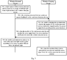
Fig. 5 is a flow chart of a method for limiting a number of wireless powered devices being charged wirelessly according to an exemplary aspect of the present disclosure. The method is described below by taking a case in which the method is applied to the wireless charging system shown inFig. 1 as an example. As illustrated inFig. 5 , the method includes the following steps. - In
step 501, a light receiver in the wireless powered device is moved into a range of infrared light emitted from a light emitter in the wireless charging device. - In an example, the light receiver in the wireless powered device is moved into the range of the infrared light from the light emitter, and there is no obstacle between the light receiver and the light emitter.
- In an example, the light receiver being in the range of the infrared light from the light emitter means that the infrared light emitted from the light emitter may reach all or part of the light receiver.
- In
step 502, the wireless powered device sends an access feedback to the wireless charging device. - In an example, the wireless powered device sends the access feedback to a first communication device in the wireless charging device through a second communication device in the wireless powered device.
- In an example, the first communication device and the second communication device communicate with each other in an ultra-wideband carrier-free communication mode.
- In
step 503, the wireless charging device determines whether the number of the wireless powered devices being charged wirelessly reaches an access upper limit according to the access feedback. - In an example, the wireless charging device includes a charging manager. The charging manager is configured with the access upper limit. The access upper limit is configured to control the number of the wireless powered devices accessing the wireless charging device, i.e., being charged wirelessly by the wireless charging device.
- In
step 504, when the number of the wireless powered devices reaches the access upper limit, an access rejection notification is sent to the wireless powered device. - In an example, when the number of the wireless powered devices reaches the access upper limit, since the power of the infrared light emitted from the light emitter is fixed, the power received by each wireless powered device becomes too low as the number of the wireless powered devices increases, resulting in a low charging efficiency.
- In step 505, the wireless powered device adjusts the state of the automatic light blocking plate according to the access rejection notice to block the infrared light.
- In
step 506, when the number of the wireless powered devices does not reach the access upper limit, the wireless powered devices being charged wirelessly by the wireless charging device are counted, i.e., the number of the wireless powered device is counted. - In an example, when the number of the wireless powered devices does not reach the upper access limit, the number of the wireless powered devices currently accessing the wireless charging device is counted.
- In an example, the
wireless charging device 110 includes the charging manager and the first communication device. The charging manager is configured with an access key. The wireless powereddevice 120 further includes a second communication device, and is configured to send a charging key to the first communication device through the second communication device. The charging manager is configured to control wireless charging of the wireless powereddevice 120 according to a matching between the charging key received by the first communication device and the access key. - In an example, when the charging key sent from the wireless powered
device 120 matches the access key, the wireless powereddevice 120 is enabled to be charged wirelessly through the infrared light emitted from thelight emitter 111. However, when the charging key sent from the wireless powereddevice 120 does not match the access key, thewireless charging device 110 sends the access rejection notification to the second communication device in the wireless powereddevice 120 through the first communication device. Then, the wireless powereddevice 120 stops receiving the infrared light according to the access rejection notification. - In an example, the
light receiver 121 is configured with a corresponding automatic light blocking plate, which may be in a state corresponding to any one of a light blocking state and a light transmitting state. When the automatic light blocking plate corresponds to the light blocking state, the automatic light blocking plate blocks the infrared light between thelight receiver 121 and thelight emitter 111. When the automatic light blocking plate corresponds to the light transmitting state, a position or a state of the automatic light blocking plate may be adjusted to disable the blocking between thelight receiver 121 and thelight emitter 111. The target wireless powereddevice 120 may adjust the state of the automatic light blocking plate according to the access rejection notification, for example, place the automatic light blocking plate between thelight receiver 121 and thelight emitter 111 for blocking, so as to prevent thelight receiver 121 from receiving the infrared light emitted from thelight emitter 111. - Illustratively,
Fig. 6 is a flow chart of an access control method of a wireless powered device according to an exemplary aspect of the present disclosure. The method is described below by taking a case in which the method is applied to the wireless charging system shown inFig. 1 as an example. As illustrated inFig. 6 , the method includes the following steps. - In
step 601, a light receiver in the wireless powered device is moved into the range of the infrared light emitted from the light emitter in the wireless charging device. - In an example, the light receiver in the wireless powered device is moved into the range of the infrared light from the light emitter, and there is no obstacle between the light receiver and the light emitter.
- In an example, the light receiver being in the range of the infrared light from the light emitter means that the infrared light emitted from the light emitter may reach all or part of the light receiver.
- In
step 602, the wireless powered device sends a charging key to the wireless charging device. - In an example, the wireless powered device sends the charging key to the first communication device of the wireless charging device through the second communication device of the wireless powered device.
- In an example, the first communication device and the second communication device communicate with each other in an ultra-wideband carrier-free communication mode.
- In an example, after the light receiver in the wireless powered device is moved in the range of the infrared light from the light emitter, a key input interface is displayed on the wireless powered device. Then, after the user inputs the charging key in the key input interface, the charging key is sent to the wireless charging device.
- In
step 603, the wireless charging device determines whether the charging key matches the access key. - In an example, the wireless charging device includes a charging manager. The charging manager is configured with the access key. The access key is configured to manage the wireless powered devices being charged wirelessly by the wireless charging device.
- In
step 604, when the charging key does not match the access key, an access rejection notification is sent to the wireless powered device. - When the charging key does not match the access key, the wireless powered device does not have a permission to access the wireless charging device for wireless charging. Consequently, an access rejection notification is sent to the wireless powered device.
- In step 605, the wireless powered device adjusts the state of the automatic light blocking plate according to the access rejection notification to block the infrared light.
- In
step 606, when the charging key matches the access key, the wireless powered device is enabled to be charged wirelessly through the infrared light emitted from the light emitter. - In an example, the
wireless charging device 110 may be a lamp and/or a home appliance. When thewireless charging device 110 is implemented as the lamp, the lamp includes at least one of a desk lamp, a ceiling light, a floor light and a wall lamp. - When the wireless charging device is implemented as the home appliance, the home appliance includes at least one of a television, an air conditioner, a monitoring camera and an air cleaner.
- In an example, when the
wireless charging device 110 is the lamp and/or the home appliance, thewireless charging device 110 includes a switch. When the switch is turned on, thewireless charging device 110 performs functions of the lamp and/or the home appliance and emits the infrared light through the light emitter. Alternatively, thewireless charging device 110 includes a first switch and a second switch. When the first switch is turned on, thewireless charging device 110 performs the functions of the lamp and/or the home appliance, and when the second switch is turned on, the wireless charging device emits the infrared light through the light emitter. - In an example, the wireless powered
device 120 is a wearable mobile terminal, such as a smart watch and smart glasses, and/or a handheld mobile terminal. Alternatively, the wireless powereddevice 120 may be an intelligent vehicle, an audio playing device, a home appliance, or the like. - Illustratively, an example is described below, in which the wireless charging device is the lamp, or particularly, a ceiling light. As illustrated in
Fig. 7 , aceiling light 710 is arranged on the ceiling of a room. Theceiling light 710 includes alight emitter 711 which is emitting infrared light. A wireless powereddevice 721 and a wireless powereddevice 722 are placed on a top surface of a table in the room. Alight receiver 731 is disposed on a surface of the wireless powereddevice 721. Alight receiver 732 is disposed on a surface of the wireless powereddevice 722. There is no obstacle between thelight receivers light emitter 711. Consequently, the wireless powereddevices light emitter 711 through thelight receivers device 721 and the wireless powereddevice 722. - Illustratively, another example is described below, in which the lamp is a desk lamp. As illustrated in
Fig. 8 , adesk lamp 810 is placed on a top surface of a table. Thedesk lamp 810 includes alight emitter 811 which is emitting infrared light. A wireless powereddevice 820 is placed below the desk lamp. Alight receiver 821 is disposed on a rear surface of the wireless powereddevice 820. There is no obstacle between thelight receiver 821 and thelight emitter 811. Consequently, the wireless powereddevice 820 may receive the infrared light emitted from thelight emitter 811 through thelight receiver 821, and convert the light energy of the infrared light into the electrical energy, so as to supply power to the wireless powereddevice 820. - Illustratively, still another example is described below, in which the wireless charging device is a home appliance, e.g., an air cleaner. As illustrated in
Fig. 9 , anair cleaner 910 includes alight emitter 911 which is emitting infrared light. A user is using a wireless powereddevice 920. Alight receiver 921 is disposed on a rear surface of the wireless powereddevice 920. There is no obstacle between thelight receiver 921 and thelight emitter 911. Consequently, the wireless powereddevice 920 may receive the infrared light emitted from thelight emitter 911 through thelight receiver 921, and convert the light energy of the infrared light into the electrical energy, so as to supply power to the wireless powereddevice 920. - Although in the above examples, the
wireless charging device 110 and the wireless powereddevice 120 being implemented as a wireless charging system are illustrated, it should be noted that thewireless charging device 110 and the wireless powereddevice 120 in the wireless charging system may be implemented as two discrete mobile terminals. - According to examples of the present disclosure, a wireless charging system includes a wireless charging device, including a light emitter configured to emit infrared light; and a wireless powered device, having a surface with a light receiver disposed thereon, the light receiver being configured to receive the infrared light emitted from the light emitter, where the light receiver is further configured to convert light energy of the received infrared light into electrical energy and supply the electrical energy to power the wireless powered device.
- In an example, the light receiver is disposed at a position on at least one of a front surface and a rear surface of the wireless powered device. The front surface is a surface corresponding to a display screen in the wireless powered device, and the rear surface is a surface corresponding to a rear housing in the wireless powered device. Alternatively, the front surface is a surface corresponding to a primary display screen, and the rear surface is a surface corresponding to a secondary display screen.
- In an example, the light receiver is disposed at a position on a side surface of the wireless powered device; and the side surface of the wireless powered device includes at least one of a top surface, a bottom surface, a left side surface and a right side surface of the wireless powered device.
- In an example, the wireless powered device includes a foldable display screen including a first screen area and a second screen area; and the light receiver is disposed between the first screen area and the second screen area in the foldable display screen.
- In an example, the light receiver includes a photovoltaic cell configured to convert the light energy of the received infrared light into the electrical energy.
- In an example, when the light receiver is disposed within an emission range of the infrared light from the light emitter, and there is no obstacle between the light receiver and the light emitter, the light receiver is configured to receive the infrared light emitted from the light emitter.
- In an example, the wireless charging device further includes a charging manager, the charging manager being configured with an access upper limit which indicates a maximum number of wireless powered devices to be charged wirelessly through the infrared light emitted from the light emitter, and being configured to control a number of the wireless powered devices being charged wirelessly through the infrared light by using the access upper limit.
- In an example, the wireless charging device further includes: a charging manager configured with an access key and a first communication device; and the wireless powered device further includes a second communication device. The wireless powered device is configured to send a charging key to the first communication device through the second communication device, and the charging manager is configured to control wireless charging of the wireless powered device according to a matching between the charging key received by the first communication device and the access key.
- In an example, the wireless charging device is a lamp and/or a home appliance. When the wireless charging device is implemented as the lamp, the lamp includes at least one of a desk lamp, a ceiling light, a floor light and a wall lamp. When the wireless charging device is implemented as the home appliance, the home appliance includes at least one of a television, an air conditioner, a monitoring camera and an air cleaner.
- In an example, the wireless powered device is a wearable mobile terminal and/or a handheld mobile terminal.
- According to examples of the present disclosure, a wireless charging device is provided. The wireless charging device includes a light emitter configured to emit infrared light. The infrared light is configured to supply power to a wireless powered device. A light receiver configured to receive the infrared light emitted from the light emitter is disposed on a surface of the wireless powered device.
- In an example, the wireless charging device further includes a charging manager, the charging manager being configured with an access upper limit which indicates a maximum number of wireless powered devices to be charged wirelessly through the infrared light emitted from the light emitter, and being configured to control a number of the wireless powered devices being charged wirelessly through the infrared light by using the access upper limit.
- In an example, the wireless charging device further includes a charging manager configured with an access key, and a first communication device. The wireless charging device is configured to receive a charging key sent from the wireless powered device through the first communication device, and the charging manager is configured to control wireless charging of the wireless powered device according to a matching between the charging key received by the first communication device and the access key.
- In an example, the wireless charging device is a lamp and/or a home appliance. When the wireless charging device is implemented as the lamp, the lamp includes at least one of a desk lamp, a ceiling light, a floor light and a wall lamp. When the wireless charging device is implemented as the home appliance, the home appliance includes at least one of a television, an air conditioner, a monitoring camera and an air cleaner.
- According to examples of the present disclosure, a wireless powered device is provided. A light receiver is disposed on a surface of the wireless powered device. The light receiver is configured to receive infrared light emitted from a light emitter of a wireless charging device, and is further configured to convert light energy of the received infrared light into electrical energy and supply the electrical energy to power the wireless powered device.
- In an example, the light receiver is disposed at a position on at least one of a front surface and a rear surface of the wireless powered device. The front surface is a surface corresponding to a display screen in the wireless powered device, and the rear surface is a surface corresponding to a rear housing of the wireless powered device. Alternatively, the front surface is a surface corresponding to a primary display screen, and the rear surface is a surface corresponding to a secondary display screen.
- In an example, the light receiver is disposed at a position on a side surface of the wireless powered device. The side surface of the wireless powered device includes at least one of a top surface, a bottom surface, a left side surface and a right side surface of the wireless powered device
- In an example, the wireless powered device includes a foldable display screen including a first screen area and a second screen area. The light receiver is disposed between the first screen area and the second screen area of the foldable display screen.
- In an example, the light receiver includes a photovoltaic cell configured to convert the light energy of the received infrared light into the electrical energy.
- In an example, when the light receiver is disposed within an emission range of the infrared light from the light emitter, and there is no obstacle between the light receiver and the light emitter, the light receiver is configured to receive the infrared light emitted from the light emitter.
- By providing the light emitter in the wireless charging device and providing the light receiver on the surface of the wireless powered device, the wireless powered device may receive the infrared light emitted from the light emitter of the wireless charging device through the light receiver, so as to convert the light energy of the infrared light into the electrical energy for supplying power to the wireless powered device, which eliminates the necessity for keeping a short distance between the wireless charging device and the wireless powered device and thereby avoids poor flexibility of the wireless powered device during the wireless charging process.
- It should be understood that "a plurality of' herein means two or more, and "and/or," describing an association of associated objects, means that there may be three relationships. For example, A and/or B may mean that: A exists independently, A and B exist simultaneously, and B exists independently. The character "/" generally indicates that the associated objects are in an "or" relationship.
- The above-mentioned serial numbers of the examples of the present disclosure are merely for description and do not represent advantages or disadvantages of the examples.
- It would be understood by those skilled in the art that all or a part of the steps carried by the method in the above-described examples may be completed by hardware, or by relevant hardware instructed by a program. The program may be stored in a computer readable storage medium. The above-mentioned storage medium may be a read-only memory, a magnetic disk, an optical disk or the like.
- The above descriptions are merely some examples of the present disclosure, and are not intended to limit the present disclosure.
Claims (16)
- A wireless charging system (100), comprising:a wireless charging device (110), comprising a light emitter (111) configured to emit infrared light; anda wireless powered device (120), having a surface with a light receiver (121) disposed thereon, the light receiver (121) being configured to receive the infrared light emitted from the light emitter (111),wherein the light receiver (121) is further configured to convert light energy of the received infrared light into electrical energy and supply the electrical energy to power the wireless powered device (120).
- The wireless charging system according to claim 1, wherein
the light receiver (121) is disposed at a position on at least one of a front surface and a rear surface of the wireless powered device (120),
wherein the front surface is a surface corresponding to a display screen in the wireless powered device, and the rear surface is a surface corresponding to a rear housing in the wireless powered device; or
the front surface is a surface corresponding to a primary display screen in the wireless powered device, and the rear surface is a surface corresponding to a secondary display screen in the wireless powered device. - The wireless charging system according to claim 1 or 2, wherein
the light receiver (121) is disposed at a position on a side surface of the wireless powered device (120); and
the side surface of the wireless powered device comprises at least one of a top surface, a bottom surface, a left side surface and a right side surface of the wireless powered device. - The wireless charging system according to any of claims 1-3, wherein the wireless powered device (120) comprises a foldable display screen comprising a first screen area and a second screen area; and
the light receiver is disposed between the first screen area and the second screen area in the foldable display screen. - The wireless charging system according to any of claims 1-4, wherein the light receiver (121) comprises a photovoltaic cell configured to convert the light energy of the received infrared light into the electrical energy.
- The wireless charging system according to any of claims 1-5, wherein
when the light receiver (121) is disposed within an emission range of the infrared light from the light emitter (111) and there is no obstacle between the light receiver and the light emitter, the light receiver is configured to receive the infrared light emitted from the light emitter. - The wireless charging system according to any of claims 1-6, wherein
the wireless charging device (110) further comprises a charging manager, the charging manager being configured with an access upper limit which indicates a maximum number of wireless powered devices (120) to be charged wirelessly through the infrared light emitted from the light emitter (111), and being configured to control a number of the wireless powered devices being charged wirelessly through the infrared light by using the access upper limit. - The wireless charging system according to any of claims 1-6, wherein
the wireless charging device (110) further comprises a charging manager and a first communication device, the charging manager being configured with an access key; and
the wireless powered device (120) further comprises a second communication device,
wherein the wireless powered device is configured to send a charging key to the first communication device through the second communication device; and
the charging manager is configured to control wireless charging of the wireless powered device according to a matching between the charging key received by the first communication device and the access key. - The wireless charging system according to any of claims 1-8, wherein the wireless charging device (110) is a lamp and/or a home appliance;
wherein when the wireless charging device (110) is the lamp, the lamp comprises at least one of a desk lamp, a ceiling light, a floor light and a wall lamp; and
when the wireless charging device (110) is the home appliance, the home appliance comprises at least one of a television, an air conditioner, a monitoring camera and an air cleaner. - The wireless charging system according to any of claims 1-9, wherein the wireless powered device (120) is a wearable mobile terminal and/or a handheld mobile terminal.
- A wireless charging device (110), comprising a light emitter (111) configured to emit infrared light,
wherein the infrared light is configured to supply power to a wireless powered device (120), and
a light receiver (121) configured to receive the infrared light emitted from the light emitter (111) is disposed on a surface of the wireless powered device (120). - The wireless charging device according to claim 11 or 12, wherein the wireless charging device (110) further comprises a charging manager, the charging manager being configured with an access upper limit which indicates a maximum number of wireless powered devices to be charged wirelessly through the infrared light emitted from the light emitter, and being configured to control a number of the wireless powered devices (120) being charged wirelessly through the infrared light by using the access upper limit.
- The wireless charging device according to claim 11 or 12, wherein the wireless charging device (110) further comprises a charging manager and a first communication device, the charging manager being configured with an access key,
wherein the wireless charging device (110) is configured to receive a charging key sent from the wireless powered device through the first communication device, and
the charging manager is configured to control wireless charging of the wireless powered device according to a matching between the charging key received by the first communication device and the access key. - A wireless powered device (120), having a surface with a light receiver (121) disposed thereon,
wherein the light receiver is configured to receive infrared light emitted from a light emitter (111) of a wireless charging device (110), convert light energy of the received infrared light into electrical energy, and supply the electrical energy to power the wireless powered device (120). - The wireless powered device according to claim 14, wherein
the light receiver (121) is disposed at a position on at least one of a front surface and a rear surface of the wireless powered device (120) ;
wherein the front surface is a surface corresponding to a display screen in the wireless powered device, and the rear surface is a surface corresponding to a rear housing of the wireless powered device; or
the front surface is a surface corresponding to a primary display screen in the wireless powered device, and the rear surface is a surface corresponding to a secondary display screen in the wireless powered device. - The wireless powered device according to claim 14, wherein
when the light receiver (121) is disposed within an emission range of the infrared light from the light emitter (111), and there is no obstacle between the light receiver and the light emitter, the light receiver is configured to receive the infrared light emitted from the light emitter.
Applications Claiming Priority (1)
| Application Number | Priority Date | Filing Date | Title |
|---|---|---|---|
| CN201910325221.9A CN111835098B (en) | 2019-04-22 | 2019-04-22 | Wireless charging system, wireless charging device and wireless power receiving device |
Publications (1)
| Publication Number | Publication Date |
|---|---|
| EP3731365A1 true EP3731365A1 (en) | 2020-10-28 |
Family
ID=69005513
Family Applications (1)
| Application Number | Title | Priority Date | Filing Date |
|---|---|---|---|
| EP19219211.0A Pending EP3731365A1 (en) | 2019-04-22 | 2019-12-23 | Wireless charging system, wireless charging device and wireless powered device |
Country Status (3)
| Country | Link |
|---|---|
| US (1) | US11316379B2 (en) |
| EP (1) | EP3731365A1 (en) |
| CN (1) | CN111835098B (en) |
Families Citing this family (5)
| Publication number | Priority date | Publication date | Assignee | Title |
|---|---|---|---|---|
| US11394247B1 (en) * | 2017-08-30 | 2022-07-19 | Roman Tsibulevskiy | Charging technologies |
| US10716192B1 (en) | 2017-08-30 | 2020-07-14 | Roman Tsibulevskiy | Charging technologies |
| CN113890137A (en) * | 2021-09-24 | 2022-01-04 | 青岛海尔空调器有限总公司 | Method and device for wireless charging, household appliance and storage medium |
| EP4250518A1 (en) * | 2022-03-25 | 2023-09-27 | BrainLit AB | Charging a battery of a battery powered device |
| JP2024007141A (en) * | 2022-07-05 | 2024-01-18 | 株式会社Nttファシリティーズ | lighting equipment |
Citations (4)
| Publication number | Priority date | Publication date | Assignee | Title |
|---|---|---|---|---|
| CN105186618A (en) * | 2015-09-21 | 2015-12-23 | 江苏腾威电子有限公司 | Infrared charger, infrared charging external device and infrared charging method |
| DE102016209151A1 (en) * | 2016-05-25 | 2017-11-30 | Fraunhofer-Gesellschaft zur Förderung der angewandten Forschung e.V. | Wireless charging device |
| WO2018008919A1 (en) * | 2016-07-08 | 2018-01-11 | 엘지전자 주식회사 | Wireless power transmission apparatus and method therefor |
| US20180375340A1 (en) * | 2014-08-21 | 2018-12-27 | Energous Corporation | User-configured operational parameters for wireless power transmission control |
Family Cites Families (22)
| Publication number | Priority date | Publication date | Assignee | Title |
|---|---|---|---|---|
| US8781538B2 (en) * | 2007-05-30 | 2014-07-15 | Kyocera Corporation | Portable terminal, portable apparatus and supply power control method |
| CN102324775A (en) * | 2008-03-12 | 2012-01-18 | 财团法人工业技术研究院 | charging device |
| US9124213B2 (en) * | 2010-02-19 | 2015-09-01 | Qualcomm Incorporated | Method and apparatus for cooling and energy capture in an electronic device via a photovoltaics |
| KR101672736B1 (en) * | 2010-05-14 | 2016-11-04 | 삼성전자주식회사 | Apparatus and method for power and data transmission using mobile device |
| WO2012012008A2 (en) * | 2010-07-23 | 2012-01-26 | Electric Transportation Engineering Corp. | System for advertising and communicating at a vehicle charging station and method of using the same |
| JP2012210056A (en) * | 2011-03-29 | 2012-10-25 | Kyocera Corp | Non contact charge system, control method of the non contact charge system, portable electronic apparatus, and charger |
| US9252628B2 (en) * | 2013-05-10 | 2016-02-02 | Energous Corporation | Laptop computer as a transmitter for wireless charging |
| US9837846B2 (en) * | 2013-04-12 | 2017-12-05 | Mojo Mobility, Inc. | System and method for powering or charging receivers or devices having small surface areas or volumes |
| US9263910B2 (en) * | 2014-02-06 | 2016-02-16 | Lenovo (Singapore) Pte. Ltd. | Wireless charging system for multi-mode device |
| US20150326053A1 (en) * | 2014-05-09 | 2015-11-12 | Lenovo (Singapore) Pte. Ltd. | Foldable wireless charging system |
| US9692250B2 (en) * | 2014-06-27 | 2017-06-27 | Intel Corporation | Systems and methods for smart wireless charging |
| WO2016059514A1 (en) * | 2014-10-17 | 2016-04-21 | Semiconductor Energy Laboratory Co., Ltd. | Electronic device |
| US9853489B2 (en) * | 2015-01-22 | 2017-12-26 | Alta Devices, Inc. | Charging station for mobile device with solar panel |
| US9941748B2 (en) * | 2015-07-15 | 2018-04-10 | Flextronics Ap, Llc | Optical communication and charging device and method of use |
| CN105186617A (en) * | 2015-09-21 | 2015-12-23 | 江苏腾威电子有限公司 | Infrared charging system and infrared charging method |
| CN105449786B (en) * | 2015-12-31 | 2019-02-05 | 联想(北京)有限公司 | An information processing method and electronic device |
| CN107134817B (en) * | 2016-02-29 | 2020-09-08 | 北京小米移动软件有限公司 | Wireless charging system and method |
| US10218228B2 (en) * | 2016-07-01 | 2019-02-26 | Intel Corporation | Detecting an object on a wireless charging device |
| CA3038974A1 (en) * | 2016-09-30 | 2018-04-05 | View, Inc. | Wirelessly powered and powering electrochromic windows |
| US10992158B2 (en) * | 2017-05-16 | 2021-04-27 | Glover 38Th St, Holdings Llc | Systems, devices, and/or methods for managing wireless electrical grid location or personal area network (WiGL) energy |
| CN112787419A (en) * | 2019-11-04 | 2021-05-11 | 北京小米移动软件有限公司 | Wireless charging transmitter, terminal and wireless charging method |
| CN110932347B (en) * | 2019-11-20 | 2022-02-22 | 北京小米移动软件有限公司 | Information processing method and device, mobile device and storage medium |
-
2019
- 2019-04-22 CN CN201910325221.9A patent/CN111835098B/en active Active
- 2019-11-27 US US16/698,903 patent/US11316379B2/en active Active
- 2019-12-23 EP EP19219211.0A patent/EP3731365A1/en active Pending
Patent Citations (5)
| Publication number | Priority date | Publication date | Assignee | Title |
|---|---|---|---|---|
| US20180375340A1 (en) * | 2014-08-21 | 2018-12-27 | Energous Corporation | User-configured operational parameters for wireless power transmission control |
| CN105186618A (en) * | 2015-09-21 | 2015-12-23 | 江苏腾威电子有限公司 | Infrared charger, infrared charging external device and infrared charging method |
| DE102016209151A1 (en) * | 2016-05-25 | 2017-11-30 | Fraunhofer-Gesellschaft zur Förderung der angewandten Forschung e.V. | Wireless charging device |
| WO2018008919A1 (en) * | 2016-07-08 | 2018-01-11 | 엘지전자 주식회사 | Wireless power transmission apparatus and method therefor |
| US20190207431A1 (en) * | 2016-07-08 | 2019-07-04 | Lg Electronics Inc. | Wireless power transmission apparatus and method therefor |
Also Published As
| Publication number | Publication date |
|---|---|
| CN111835098B (en) | 2022-04-22 |
| US20200336016A1 (en) | 2020-10-22 |
| US11316379B2 (en) | 2022-04-26 |
| CN111835098A (en) | 2020-10-27 |
Similar Documents
| Publication | Publication Date | Title |
|---|---|---|
| US11316379B2 (en) | Wireless charging system, wireless charging device and wireless powered device | |
| US12573889B2 (en) | Wireless terminal apparatus and wireless power transmitter | |
| US10790694B2 (en) | Wireless power transmitters and receivers, and method for permitting a wireless power receiver by a wireless power transmitter | |
| CN102027690B (en) | Wireless power transfer for appliances and devices | |
| US9159220B2 (en) | Lighting apparatus having an audio device and method of controlling the same | |
| US10425516B2 (en) | Projector housing for iphone | |
| CN103942944A (en) | Infrared signal-control smart home and subsidiary systems thereof | |
| EP3954066B1 (en) | An optical wireless charging and data tranmission system | |
| US10225912B2 (en) | System and apparatus for selectively interrupting a power supply | |
| CN107113328B (en) | Control apparatus, control method thereof, and integrated control system | |
| CN105979487A (en) | Method and system for configuring office partitions according to positioning information of mobile terminal | |
| US20190271755A1 (en) | Activation of a transmitting device of a lighting device | |
| ES2932610T3 (en) | Upgrade smart home control device with power module, charger and base | |
| US20220062468A1 (en) | Luminaire with disinfection light exposure and dosage limit control protocol and sensor integration with height controller | |
| EP3716240B1 (en) | Wireless communication terminal, fire alarm, and management system | |
| EP3817514B1 (en) | Wireless lighting control system with automatic emergency mode exit network protocol | |
| CN205068338U (en) | External member of touch -sensitive screen imbeds on refrigerator door | |
| CN107844157A (en) | A kind of projector's standby power consumption control circuit, device and equipment | |
| CN203933643U (en) | A kind of wireless infrared repeater | |
| CN107622653A (en) | Method and apparatus for controlling household electrical appliance | |
| CN105204689A (en) | Kit for embedding touch screen on refrigerator door and application method of kit | |
| US20170322618A1 (en) | Electric device control apparatus, and electric device control method using same | |
| CN103942939A (en) | Device and system for intensively controlling household appliances | |
| CN208873017U (en) | A kind of voice switch panel | |
| US9560009B1 (en) | Systems and methods for commissioning a wireless lighting device with a magnetic reed switch |
Legal Events
| Date | Code | Title | Description |
|---|---|---|---|
| PUAI | Public reference made under article 153(3) epc to a published international application that has entered the european phase |
Free format text: ORIGINAL CODE: 0009012 |
|
| STAA | Information on the status of an ep patent application or granted ep patent |
Free format text: STATUS: THE APPLICATION HAS BEEN PUBLISHED |
|
| AK | Designated contracting states |
Kind code of ref document: A1 Designated state(s): AL AT BE BG CH CY CZ DE DK EE ES FI FR GB GR HR HU IE IS IT LI LT LU LV MC MK MT NL NO PL PT RO RS SE SI SK SM TR |
|
| AX | Request for extension of the european patent |
Extension state: BA ME |
|
| STAA | Information on the status of an ep patent application or granted ep patent |
Free format text: STATUS: REQUEST FOR EXAMINATION WAS MADE |
|
| 17P | Request for examination filed |
Effective date: 20201104 |
|
| RBV | Designated contracting states (corrected) |
Designated state(s): AL AT BE BG CH CY CZ DE DK EE ES FI FR GB GR HR HU IE IS IT LI LT LU LV MC MK MT NL NO PL PT RO RS SE SI SK SM TR |
|
| RIN1 | Information on inventor provided before grant (corrected) |
Inventor name: BAI, JIAN Inventor name: PAN, YAJUN Inventor name: WEI, SHUJUN |
|
| STAA | Information on the status of an ep patent application or granted ep patent |
Free format text: STATUS: EXAMINATION IS IN PROGRESS |
|
| 17Q | First examination report despatched |
Effective date: 20211123 |
|
| GRAP | Despatch of communication of intention to grant a patent |
Free format text: ORIGINAL CODE: EPIDOSNIGR1 |
|
| STAA | Information on the status of an ep patent application or granted ep patent |
Free format text: STATUS: GRANT OF PATENT IS INTENDED |
|
| INTG | Intention to grant announced |
Effective date: 20260318 |