EP3731341A1 - Vehicle-mounted antenna device - Google Patents
Vehicle-mounted antenna device Download PDFInfo
- Publication number
- EP3731341A1 EP3731341A1 EP18892764.4A EP18892764A EP3731341A1 EP 3731341 A1 EP3731341 A1 EP 3731341A1 EP 18892764 A EP18892764 A EP 18892764A EP 3731341 A1 EP3731341 A1 EP 3731341A1
- Authority
- EP
- European Patent Office
- Prior art keywords
- antenna
- metal plate
- base
- metal
- antenna device
- Prior art date
- Legal status (The legal status is an assumption and is not a legal conclusion. Google has not performed a legal analysis and makes no representation as to the accuracy of the status listed.)
- Granted
Links
Images







Classifications
-
- H—ELECTRICITY
- H01—ELECTRIC ELEMENTS
- H01Q—ANTENNAS, i.e. RADIO AERIALS
- H01Q1/00—Details of, or arrangements associated with, antennas
- H01Q1/27—Adaptation for use in or on movable bodies
- H01Q1/32—Adaptation for use in or on road or rail vehicles
- H01Q1/325—Adaptation for use in or on road or rail vehicles characterised by the location of the antenna on the vehicle
- H01Q1/3275—Adaptation for use in or on road or rail vehicles characterised by the location of the antenna on the vehicle mounted on a horizontal surface of the vehicle, e.g. on roof, hood, trunk
-
- H—ELECTRICITY
- H01—ELECTRIC ELEMENTS
- H01Q—ANTENNAS, i.e. RADIO AERIALS
- H01Q1/00—Details of, or arrangements associated with, antennas
- H01Q1/12—Supports; Mounting means
-
- H—ELECTRICITY
- H01—ELECTRIC ELEMENTS
- H01Q—ANTENNAS, i.e. RADIO AERIALS
- H01Q1/00—Details of, or arrangements associated with, antennas
- H01Q1/12—Supports; Mounting means
- H01Q1/22—Supports; Mounting means by structural association with other equipment or articles
-
- H—ELECTRICITY
- H01—ELECTRIC ELEMENTS
- H01Q—ANTENNAS, i.e. RADIO AERIALS
- H01Q1/00—Details of, or arrangements associated with, antennas
- H01Q1/48—Earthing means; Earth screens; Counterpoises
-
- H—ELECTRICITY
- H01—ELECTRIC ELEMENTS
- H01Q—ANTENNAS, i.e. RADIO AERIALS
- H01Q1/00—Details of, or arrangements associated with, antennas
- H01Q1/52—Means for reducing coupling between antennas; Means for reducing coupling between an antenna and another structure
-
- H—ELECTRICITY
- H01—ELECTRIC ELEMENTS
- H01Q—ANTENNAS, i.e. RADIO AERIALS
- H01Q1/00—Details of, or arrangements associated with, antennas
- H01Q1/52—Means for reducing coupling between antennas; Means for reducing coupling between an antenna and another structure
- H01Q1/528—Means for reducing coupling between antennas; Means for reducing coupling between an antenna and another structure reducing the re-radiation of a support structure
-
- H—ELECTRICITY
- H01—ELECTRIC ELEMENTS
- H01Q—ANTENNAS, i.e. RADIO AERIALS
- H01Q5/00—Arrangements for simultaneous operation of antennas on two or more different wavebands, e.g. dual-band or multi-band arrangements
- H01Q5/30—Arrangements for providing operation on different wavebands
- H01Q5/307—Individual or coupled radiating elements, each element being fed in an unspecified way
Definitions
- the present invention relates to an antenna device for vehicle that is attached to a roof of a vehicle.
- the antenna device for vehicle accommodating an antenna element in a streamlined case in consideration of fluid resistance.
- the antenna device for vehicle is mounted on a center in a rear portion of the roof and may be referred to as “shark fin antenna", "dolphin antenna”, or the like because of the figure of the vehicle with the antenna device for vehicle mounted and the appearance of the antenna device for vehicle.
- Patent Literature 1 specifically discloses an antenna device for vehicle in which an antenna case is put on a resin base and a space for accommodating a metal base functioning as a ground plate, an antenna element, and so forth is thereby defined.
- Patent Literature 1 describes a structure which is provided with a conductor plate having a plate spring portion between the metal base and a roof and thereby prevents a decrease in antenna gain due to unnecessary resonance. That is, in a configuration of Patent Literature 1, a capacitance is increased by the conductor plate provided between the metal base and the roof, its resonance frequency is shifted to a lower side than a communication frequency band of the antenna element, and a decrease in antenna gain may thereby be prevented.
- Patent Literature 1 Japanese Patent Laid-open No. 2016-32166
- Patent Literature 1 waterproofing is conducted for a gap between a resin base and a roof by a pad, a sealing member, or the like, and reaching of rainwater and so forth to a portion around a conductor plate is prevented as much as possible.
- the shape of the roof as a portion to which an antenna device for vehicle is mounted is not flat.
- the roof has a mildly curved surface, the manner of the curve is different depending on the kind of vehicle or the like on which the antenna device for vehicle is mounted.
- a drastic measure against such corrosion of the conductor plate is omission of the conductor plate. Then, a function for adjusting a resonance frequency of unnecessary resonance so as to be out of communication frequencies, which is given by the conductor plate, has to be ensured by another method.
- the metal base is a precision die-cast product of aluminum or the like.
- one kind of metal base works adequately if a long side dimension of the metal base is made longer and the resonance frequency of the unnecessary resonance is thereby sufficiently separated from a lower limit of a communication frequency band with a relatively high safety factor.
- this may not be considered as a really preferable solution in terms of costs for the antenna device for vehicle, size reduction of the antenna device for vehicle, appearance of the antenna device for vehicle when mounted on the vehicle, and so forth.
- the capacitance occurring between the metal base and the roof is not determined.
- the metal base is designed very well, a case may occur where designed performance may not sufficiently be provided depending on the kind of vehicle or the like on which the metal base is mounted.
- a challenge for the present invention is to provide a technique for realizing an antenna device for vehicle that prevents a decrease in antenna gain due to unnecessary resonance by a method other than providing a conductor plate between a metal plate and a roof.
- a first aspect of the present invention provides an antenna device for vehicle that is attached to a roof of a vehicle, the antenna device for vehicle including: an antenna base; an antenna case covering the antenna base from above; and an antenna element provided inside the antenna case, in which the antenna base has a metal base fixed to the roof and a metal plate electrically connected with the metal base.
- the metal plate forms an inductance and a capacitance between the metal plate and the roof, and a resonance frequency of unnecessary resonance may thereby be adjusted.
- a resonance frequency of unnecessary resonance may be adjusted even if a component corresponding to a conductor plate described in Patent Literature 1 is not provided, a decrease in antenna gain of the antenna element may be inhibited.
- adjustment of the resonance frequency of the unnecessary resonance is achieved by the metal plate that may be fabricated by sheet metal, and it thereby becomes possible to prepare the metal plates for plural different specifications inexpensively and easily.
- the metal base is provided as a common component, it becomes possible to change the unnecessary resonance occurring between the metal base and the roof easily and inexpensively in accordance with the used metal plate and the mounting positions of the metal plate, and it becomes possible to handle a decrease easily and inexpensively in antenna gain due to the unnecessary resonance for plural kinds of vehicles.
- the antenna base may have a shape which has a front-rear direction of the vehicle as a longitudinal direction in an attachment attitude to the roof, the metal plate may be provided on a front end side and/or a rear end side of the metal base in the attachment attitude, and an electrical length which includes the metal base and the metal plate may be longer than an electrical length of only the metal base in the longitudinal direction.
- the problem may be solved without changing a lateral width of the antenna device for vehicle.
- the antenna device for vehicle in design taking into account air resistance in vehicle travel may be formed.
- the electrical length which includes the metal base and the metal plate is longer than the electrical length of only the metal base, the resonance frequency of the unnecessary resonance is shifted to a low frequency side of a communication frequency band of the antenna element, and a decrease in antenna gain may thereby be inhibited.
- the metal plate may have a meander shape or a spiral shape.
- the electrical length may more effectively be increased than employing a metal plate in a simple rectangular shape.
- a long electrical length may be obtained, it becomes possible to separate the resonance frequency of the unnecessary resonance farther from the communication frequency band.
- size reduction of the antenna device for vehicle may be realized. Realization of a small-sized antenna device for vehicle means that a decrease in the installation area with respect to the roof of the vehicle may be realized. This results in a less difference in a decrease effect of antenna gain due to a difference in a roof shape, and in spite of a single specification, a stable decrease inhibition effect of antenna gain may be obtained for plural vehicles.
- the antenna base may have an electrical length adjustment circuit, which adjusts an electrical length between the metal base and the metal plate, and the metal base and the metal plate may be electrically connected together via the electrical length adjustment circuit.
- the electrical length may be changed by the electrical length adjustment circuit, size reduction of the antenna device for vehicle may be intended.
- the metal base may have a projection portion for fixing to the roof, and a resonance frequency that occurs due to the roof and the antenna base that are electrically connected together via the projection portion may be out of a communication frequency band of the antenna element.
- the antenna device for vehicle may be realized that may easily secure the fixing strength to the roof, provide a precise electrical connection between the metal base and the roof, and further provide similar effects to the above-described aspect by the metal plate.
- the antenna base may have a resin base, and the metal plate may be arranged on the resin base.
- the antenna device for vehicle may be realized in which the metal plate is arranged on the resin base.
- the resin base may have a positioning shape portion that inhibits a position shift of the metal plate from a prescribed position of the metal plat.
- the metal plate may easily be arranged in the prescribed position. Further, a position shift of the metal plate from the prescribed position of the metal plate may be inhibited. Accordingly, attachment work of the metal plate may become easy.
- the antenna device for vehicle may further include a second antenna element being different from the antenna element, in which a part or the whole of the second antenna element may be arranged so as to be positioned above the metal plate.
- the antenna device for vehicle may be realized in which the second antenna element is arranged such that a part or the whole of the second antenna element is positioned above the metal plate.
- the metal base and the metal plate may use different materials.
- the metal base and the metal plate may use a same material.
- a second aspect of the present invention provides an antenna device for vehicle that is attached to a roof of a vehicle, the antenna device for vehicle including: an antenna base having a metal plate fixed to the roof and a resin base; an antenna case covering the antenna base from above; and an antenna element provided inside the antenna case, in which the metal plate is arranged on the resin base.
- the antenna device for vehicle that provides similar actions and effects to the first aspect, may be configured.
- a part or the whole of the antenna element may be positioned above the metal plate, and the metal plate may be formed such that a portion positioned below the antenna element is partially hollowed out.
- the antenna base may have a shape which has a front-rear direction of the vehicle as a longitudinal direction in an attachment attitude to the roof, and the metal plate may be provided on a front side and/or a rear side of the antenna base in the attachment attitude.
- the problem may be solved without changing a lateral width of the antenna device for vehicle.
- the antenna device for vehicle in design taking into account air resistance in vehicle travel may be formed.
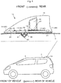
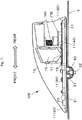
- Figure 1 is a side perspective view that illustrates a configuration example of an antenna device 10 of this embodiment.
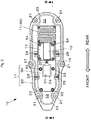
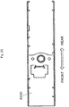
- Figure 2 is a plan view of a state where an antenna case 13 of the antenna device 10 of this embodiment is detached, that is, an internal plan view.
- Figure 3 is a cross-sectional view taken along line III-III in Figure 2 .
- the antenna device 10 is an antenna device designed on the assumption that it is mounted on an exterior structure that corresponds to a roof 3 of a vehicle 5 (such as a passenger vehicle, a truck, or an agricultural machine, for example) and is an antenna device that incorporates an antenna element and so forth in a case.
- "Front and rear" in the antenna device 10 denote the same directions as front and rear of the vehicle 5 in which the antenna device 10 is mounted on the roof 3 and mean the directions illustrated in Figure 1 . That is, those are the front-rear direction along a streamlined external appearance, the side of a relatively low and tapered shape (the left side in Figure 1 ) is set as front of the antenna device, and the opposite direction (the right side in Figure 1 ) is set as rear.
- the antenna device 10 has an antenna base 11 and a resin antenna case 13 that covers a portion above it.
- the antenna case 13 is usually made of a non-translucent resin such that an internal portion may not be seen, but Figure 1 depicts only a contour line of the antenna case 13 as if the internal portion were seen through.
- the antenna device 10 is formed in a so-called shark fin shape that is long in the front-rear direction as the whole, has a flat mounting surface, and looks like a dorsal fin of a shark or a dolphin in a side view.
- the antenna device 10 is mounted on an upper surface of the roof 3 such that its longitudinal direction goes along the front-rear direction of the vehicle 5.
- the antenna base 11 has a shape that has the front-rear direction of the vehicle as the longitudinal direction in an attachment attitude to the roof 3 of the vehicle 5.
- a housing space is defined between the antenna base 11 and the antenna case 13 and incorporates an antenna element 15 and a substrate 17 on which various circuits for an antenna are mounted.
- configuration elements incorporated in the housing space are not limited to those but may appropriately be selected.
- one antenna element 15 is used in this embodiment, a configuration is possible that incorporates plural kinds of separate antenna elements for different purposes of use.
- the antenna base 11 of this embodiment has a resin base 20, a metal base 30, and a metal plate 40.
- the resin base 20 is a plate-shaped body that forms a main flat bottom surface of the antenna device 10 and is molded with a non-conductive resin. As illustrated in Figure 2 , in an outer circumference, the resin base 20 has plural bosses 21 for screw-fastening the antenna case 13.
- a rib 23 higher than an outer peripheral portion is formed slightly inside an outer periphery, and a pedestal portion 22 is formed inside the rib 23.
- An upper surface of the pedestal portion 22 forms a flat surface that is in parallel or generally in parallel with the bottom surface.
- a penetrating portion 24 that passes through from the face to the back of the resin base 20 is provided in a central portion of the pedestal portion 22 in a top view (see Figure 2 ). The penetrating portion 24 is used for inserting a projection portion of the metal base 30 and drawing out a cable 19.
- the pedestal portion 22 is provided with plural bosses 26 (see Figure 3 ) for screw-fastening the metal base 30, and the metal base 30 is put on (overlays) the pedestal portion 22 from above and is screw-fastened by attachment screws 28 (see Figure 2 ).
- the metal base 30 is a metal component that is long in the longitudinal direction of the antenna device 10 and is a die-cast product of an aluminum alloy, for example. As illustrated in Figure 2 and Figure 3 , the metal base 30 has a projection portion 31 (see Figure 3 ) that is provided to project below a lower surface and is for fixing to the roof 3, plural bosses 33, and plural substrate attachment screw bosses 35.
- the projection portion 31 (see Figure 3 ) is a fixing part that is inserted into the vehicle through a penetrating hole provided in the roof 3 and the penetrating portion 24.
- a capturing fastener 50 is mounted on the inserted projection portion 31, temporary positioning and retainment are conducted for the projection portion 31.
- An antenna fixing bolt 52 is then fastened into a threaded portion that is threaded in a lower end portion of the projection portion 31, and the projection portion 31 is thereby fixed to the roof 3 (in Figure 3 , the capturing fastener 50 and the antenna fixing bolt 52 are illustrated in an exploded state).
- Locking claws of the capturing fastener 50 bite into the roof 3 by fastening the antenna fixing bolt 52, and the metal base 30 and the roof 3 are electrically connected together. That is, grounding is made.
- a cable insertion hole 32 (see Figure 2 ) is provided in the metal base 30, and the cable 19 from the substrate 17 is drawn into the vehicle through the cable insertion hole 32 and the penetrating portion 24.
- the cable 19 drawn into the vehicle is connected with a signal cable wired in an internal portion of the vehicle.
- the plural bosses 33 are provided from a front side to an intermediate area of the metal base 30 and are used for fixing the metal base 30 to the resin base 20 by machine screws.
- the plural bosses 33 may be used for fixing in a case where an antenna element or the like for another purpose of use is additionally mounted.
- the substrate attachment screw bosses 35 for placing the substrate 17 on which the antenna element 15 is mounted are provided on a rear side of the metal base 30, and the metal base 30 and the substrate 17 together are fixed to the resin base 20 by substrate attachment screws 54.
- the substrate 17 and the metal base 30 are electrically connected together by the substrate attachment screws 54.
- the metal plate 40 is a metal component that is formed from a different material from the metal base 30.
- the metal plate 40 is a plate material fabricated from sheet metal and is a first electrical length adjustment element for adjusting a resonance frequency of unnecessary resonance in this embodiment.
- the thickness of the metal plate 40 may be thinner than the thickness of the metal base 30, and the strength of the metal plate 40 may be lower than the strength of the metal base 30. That is, the metal plate 40 may be formed from an inexpensive component compared to the metal base 30. Further, the metal plate 40 may be formed from a conductive resin.
- the metal plate 40 is placed on a rear end side of the pedestal portion 22 of the resin base 20 such that a plate surface is opposed to the roof 3 via the resin base 20.
- the metal plate 40 is considered as a portion of the metal base 30, it may be considered that the metal plate 40 is provided such that a top-view superimposed area of only the metal base 30, which is seen to overlap with the roof 3 in a top view, is expanded by inclusion of the metal plate 40.
- the portion is fastened and fixed to the resin base 20 together with the substrate 17 and the metal base 30 by the substrate attachment screw 54 and is electrically conducted with the substrate 17 and the metal base 30.
- the superimposed region between the metal plate 40 and the metal base 30 is desirably small.
- the superimposed region is preferably limited to the portions superimposed due to fastening those together.
- the strength of the resin base 20 may be enhanced to the strength of the resin base 20 including the metal plate 40 compared to a case where the metal plate 40 is not attached. Specifically, deformation, damage, or the like due to external force or temperature may be prevented.
- the example of Figure 1 to Figure 3 illustrates an example where fixing between the metal plate 40 and the pedestal portion 22 is achieved by screw-fastening, but fixing may be made by protrusion-recess fitting, spring fixing, pressure bonding, or the like.
- the portion of the metal plate 40 is fixed to and electrically conducted with the metal base 30 by fastening those together by the substrate attachment screw 54, but another method may be employed.
- the metal plate 40 and the metal base 30 may be electrically connected together by connecting the metal plate 40 and the metal base 30 together by substrate wiring, a connector, an electrical cord, or the like.
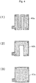
- Figure 4 is a diagram that illustrates examples of kinds of metal plates 40 in this embodiment. Plural kinds of metal plates 40 with different electrical lengths are prepared. Specifically, in each of (1) to (3) of Figure 4 , the electrical length that includes the metal base 30 and the metal plate 40 in a case where the metal base 30 and the metal plate 40 are connected side-by-side in the longitudinal direction as illustrated in Figure 1 to Figure 3 becomes longer than the electrical length of only the metal base 30 in the longitudinal direction (front-rear direction).
- a metal plate 40a of (1) of Figure 4 is designed to have notches or slits so as to form a meander shape (serpentine shape).
- design like a metal plate 40b of (2) of Figure 4 is possible in which the number of repetitions of a serpentine pattern is smaller than that of the metal plate 40a.
- a configuration is possible that has a rectangular flat plate shape without notches or slits.
- versions of the metal plate 40 are not limited to the examples of Figure 4 , but it is possible to appropriately provide other versions such as polygonal shapes and spiral shapes.
- the metal plate 40 may have a shape in which the opposite end portion to an end portion connected with the metal base 30, between both of the end portions of the metal plate 40, extends so as to surround a periphery of the metal base 30.
- the resonance frequency of the unnecessary resonance is adjusted so as to be out of a communication frequency band of the antenna element 15, and a decrease in antenna gain may be inhibited.
- an electromagnetic action occurs between the metal plate 40 and the roof 3, the electrical length of the antenna base 11 increases by the electrical length of the metal plate 40 compared to the electrical length of only the metal base 30, and the resonance frequency of the unnecessary resonance that occurs due to the roof 3 and the antenna base 11 may be lowered.
- the resonance frequency of the unnecessary resonance may be moved to a lower range than a lower limit of the communication frequency band of the antenna element 15.
- the unnecessary resonance at the frequency corresponding to the length of the metal base 30 in the longitudinal direction occurs due to the roof 3 and the metal base 30.
- the resonance frequency moves to a low range side.
- this method increases cost by extension of the length of the metal base 30. It is desired that making the metal base 30 long be avoided because the metal base 30 is a die-cast component that is expensive compared to the metal plate 40.
- preparation of different metal bases 30 for plural kinds of vehicles 5 among which shapes and so forth of the roof 3 are different becomes a factor in a cost increase.
- the resonance frequency is moved to the low range side by arranging the metal plate 40 less expensive than the metal base 30, a cost increase may be inhibited. Further, because it is sufficient that the metal base 30 is provided as a common component for plural kinds of vehicles 5 and the metal plate 40 is prepared for each of plural kinds of vehicles 5, a cost increase may also be inhibited in this point.
- Figure 5 is a graph of a voltage standing wave ratio (VSWR) regarding the antenna device 10 of this embodiment and represents differences in accordance with presence and absence of the metal plate 40.
- VSWR voltage standing wave ratio
- the antenna element 15 of the antenna device 10 of this embodiment is capable of transmission and/or reception of a signal in a carrier frequency band (for example, a band from 699 MHz to 960 MHz or a band from 1,710 MHz to 2,690 MHz) of a cellular phone.
- a carrier frequency band for example, a band from 699 MHz to 960 MHz or a band from 1,710 MHz to 2,690 MHz
- the unnecessary resonance occurs around the lower limit of the communication frequency band. In this case, it may be considered that a sufficient margin may not be obtained in consideration of a change in a mounting situation due to the shape or the like of the roof 3.
- the resonance frequency of the unnecessary resonance is lowered by providing the metal plate 40, and thereby the resonance frequency may largely be separated from the lower limit of the communication frequency band.
- the metal plate 40 formed into the meander shape like the metal plate 40a has the same installation area in a top view but may increase the electrical length compared to the metal plate 40 formed into the rectangular flat plate shape like the metal plate 40c. Consequently, the resonance frequency of the unnecessary resonance may be lowered by such an increase.
- a decrease in antenna gain due to the unnecessary resonance may be prevented by a method other than providing a conductor plate between a metal plate and a roof.
- a different version of the metal plate 40 may be prepared.
- costs for creation of the product series of course, costs for management of component stocks, and manufacture may be kept very low.
- plural kinds of metal plates 40 are supplied together from the beginning. Then, in a case where a sufficient antenna gain may not be obtained when the antenna device 10 is mounted on the vehicle, it is possible to immediately and inexpensively take measures at the site by exchanging the metal plates 40.
- a flat grounding surface may be expanded to a rear end portion side in the housing space of the antenna device 10 by providing the metal plate 40. Accordingly, in a case where an installation position of the antenna element 15 is set to a portion above the metal plate 40 or a case where another antenna element is additionally installed above the metal plate 40, the distance between these antenna elements and the grounding surface as the metal plate 40 becomes the distance as intended in design, and an antenna gain as designed may be obtained.
- the method that lowers the resonance frequency of the unnecessary resonance is employed.
- a method that conversely raises the resonance frequency of the unnecessary resonance is employed.
- the same reference numerals are provided to similar configuration elements to the first embodiment, and duplicated descriptions thereof will be omitted.
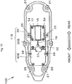
- Figure 6 is a plan view of a state where an antenna case of an antenna device 10B of this embodiment is detached.
- a metal base 30B is made shorter in the longitudinal direction (front-rear direction) than the antenna base 11 of the first embodiment.
- a metal plate 40B is provided with a gap which is provided on a front end side of the metal base 30B, and the metal plate 40B and the metal base 30B are thereby in an electrically disconnected state.
- the front-rear length of the metal base 30B of this embodiment is shorter than that of the metal base 30 of the first embodiment.
- the metal base 30B corresponds to a central portion and a rear portion in a case where the metal base 30 of the first embodiment is divided into three parts of a front portion, the central portion, and the rear portion.
- the metal plate 40B of this embodiment corresponds to the front portion in a case where the metal base 30 of the first embodiment is divided into three parts of the front portion, the central portion, and the rear portion and is attached to the resin base 20 by the attachment screws 28.
- Figure 7 is a VSWR graph about the antenna device 10B of this embodiment.
- the broken line in Figure 7 indicates a VSWR curve of a case where no metal plate 40 in the first embodiment is present and only the metal base 30 is present. Meanwhile, the thin solid line indicates a VSWR curve based on the combination of the metal base 30B and the metal plate 40B in this embodiment, and it is clear that the resonance frequency of the unnecessary resonance may be raised.
- the antenna device 10B of this embodiment may largely separates the resonance frequency of the unnecessary resonance to a higher frequency than an upper limit of the communication frequency band and may thus obtain similar effects to the antenna device 10 of the first embodiment.
- the metal plate 40 of the first embodiment is in a two-dimensional planar shape, but a three-dimensional shape such as a meander shape in which folds are provided in the vertical direction may be employed.
- the electrical length adjustment circuit 61 is a second electrical length adjustment element for adjusting the resonance frequency of the unnecessary resonance and may be realized as so-called "transmission line length adjustment circuit” or "delay circuit".
- the electrical length adjustment circuit 61 may be configured only with a coil as in (a) of Figure 12 or only with a capacitor as in (b) of Figure 12 .
- the electrical length adjustment circuit 61 may be configured with a circuit in which a capacitor and a coil are connected together in parallel as in (c) of Figure 12 or may be configured with a circuit in which a capacitor and a coil are connected together in series as in (d) of Figure 12 .
- a configuration is preferable that switches are provided and circuit constants are thereby made switchable as in (e) of Figure 12 .
- electrical lengths are made switchable by providing switches that introduce or disconnect elements such as a capacitor or a coil.
- Figure 9 is a VSWR graph regarding the antenna device 10 of the first embodiment and represents differences in accordance with presence and absence of the electrical length adjustment circuit 61.
- the thin solid line indicates a VSWR curve of a case where no electrical length adjustment circuit 61 is present and the metal base 30 and the metal plate 40 are connected together by short-circuit connection (the thin solid line curve in Figure 5 ).
- the thick solid line indicates a VSWR curve of a case where the metal base 30 and the metal plate 40 are connected together via the electrical length adjustment circuit 61 as illustrated in Figure 8 .
- the electrical length adjustment circuit 61 in this modification example is configured with a circuit as in (a) of Figure 12 , for example.
- the resonance frequency of the unnecessary resonance may be lowered because the electrical length becomes longer in a case where the metal base 30 and the metal plate 40 are electrically connected together via the electrical length adjustment circuit 61 than a case where the metal base 30 and the metal plate 40 are connected together by short-circuit connection.
- the antenna device 10B of the second embodiment may be configured such that the metal base 30B and the metal plate 40B are connected together by the electrical length adjustment circuit 61 as an antenna device 10D illustrated in Figure 10 .
- the solid line in the graph of Figure 13 indicates a VSWR curve of a case where the metal base 30B and the metal base 40B of the second embodiment are connected together by the electrical length adjustment circuit 61, and it may be understood that the resonance frequency of the unnecessary resonance may be raised.
- the electrical length adjustment circuit 61 in this modification example is configured with a circuit as in (b) of Figure 12 , for example.
- a switch that connects or disconnects the metal base 30 and the metal plate 40 may be provided in addition to the switches that introduce or disconnect elements such as a capacitor or a coil as in (e) of Figure 12 .
- a configuration including one metal plate is explained in the above embodiments, but it is possible to have a configuration including plural metal plates.
- a configuration including plural metal plates For example, it is possible to have a configuration that plural metal plates are respectively provided on a front end side and a rear end side of the metal base 30 in an attachment attitude.
- the antenna device of the above embodiments is configured to incorporate a composite antenna
- a second antenna element 15B (such as an antenna for an AM wave or an FM wave) and a second substrate 17B as its substrate are provided above the metal plate 40.
- the second antenna element 15B is positioned above the metal plate 40 from a front portion to a rear portion.
- the metal plate 40 of the first embodiment is arranged close to a rear area of the antenna device, a configuration is made in which the second antenna element 15B and the second substrate 17B are provided in a space in the rear of the antenna element 15 in the antenna case 13.
- a configuration is made in which the second antenna element 15B and the second substrate 17B are provided in a space in the rear of the antenna element 15 in the antenna case 13.
- the metal plate 40B is provided on a front side of the metal base 30
- the antenna device in a case of a configuration that the second antenna element 15B is provided above the metal plate, the antenna device is placed on whatever kind of vehicle 5, the distance between the second antenna element 15B and the metal plate becomes a fixed distance.
- a stable antenna gain as designed may be obtained.
- the metal plate may be arranged in a position interposed among the plural antenna elements.
- the metal plate is used, similar effects may be obtained by arranging a rigid substrate or a flexible substrate on which a pattern is formed. By using a substrate, an electrical length adjustment circuit may be added without increasing structural components.
- the size of the metal plate 40 in the width direction (vertical direction in Figure 2 ) is the same or generally the same as the size of the metal base 30 in the width direction, but the size is not limited to this.
- the size of the metal plate 40 in the width direction may be widened or narrowed compared to the size of the metal base 30 in the width direction. Extending the length of the metal plate 40 in the front-rear direction is more effective for shifting the frequency of the unnecessary resonance than widening the size of the metal plate 40 in the width direction.
- FIG. 14 is a diagram that illustrates an antenna device 10F as a modification example of the antenna device 10 illustrated in Figure 2 .
- a different point of the antenna device 10F from the antenna device 10 of Figure 2 is a point that a positioning shape portion 29 for inhibiting a position shift of the metal plate 40 from a prescribed position is provided in the pedestal portion 22 of the resin base 20.
- the positioning shape portion 29 includes protrusion portions 29b and a recess portion 29d but may include only either one of the protrusion portion 29b and the recess portion 29d.
- a central portion surrounded by plural protrusion portions 29b is the recess portion 29d that is recessed in a dish-like manner, and the central portion is the prescribed position in which the metal plate 40 is to be arranged.
- the metal plate 40 may easily be arranged in the prescribed position by the positioning shape portion 29.
- the protrusion portions 29b and the recess portion 29d may be used as guides in arrangement of the metal plate 40 in the prescribed position.
- the position shift of the metal plate 40 from the prescribed position may be inhibited by the protrusion portions 29b and the recess portion 29d. Accordingly, attachment work of the metal plate 40 may become easy.
- the metal base and the metal plate are used in the first embodiment, a configuration may be made only with the metal plate.
- the metal plate has an attachment mechanism to the roof. Since an expensive metal die-cast component is not used and components that connects the metal base with the metal plate are not used either, it becomes possible to reduce cost compared to the first embodiment.
- Figure 15 and Figure 16 are diagrams that illustrate an antenna device 100A of a first application example.
- Figure 15 is an oblique perspective view
- Figure 16 is a side perspective view.
- the antenna device 100A includes an antenna base 110A, an antenna case 130 covering the antenna base 110A from above, and antenna elements 151, 152, and 153 provided inside the antenna case 130.
- the antenna base 110A has a resin base 200, a metal base 300 fixed to the roof 3, and a metal plate 400A and a metal plate 400B that are electrically connected with the metal base 300.
- the metal base 300, the metal plate 400A, and the metal plate 400B are arranged on the resin base 200.
- the antenna element 151 is a patch antenna.
- the antenna element 152 is a radio antenna.
- the antenna element 153 is a keyless antenna for a keyless entry system.
- the keyless entry system is also referred to as smart entry system, and an operation frequency of the keyless antenna is 925 MHz, for example.
- the antenna device 100A includes the antenna element 153 for the keyless antenna in the rear of the metal base 300.
- the antenna element 153 is arranged on the metal plate 400B.
- the antenna device 100A includes the metal plate 400A in front of the metal base 300.
- the frequency of the unnecessary resonance that occurs due to the metal base 300, the metal plate 400A, the metal plate 400B, and the roof 3 becomes a frequency out of the band of the operation frequency of the keyless antenna. As a result, a gain of the keyless antenna may be improved.
- FIG 17 is a diagram that illustrates an antenna device 100B of a second application example and is an oblique perspective view.
- the antenna device 100B includes an antenna base 110B, the antenna case 130 covering the antenna base 110B from above, and the antenna elements 151 and 152 provided inside the antenna case 130.
- the antenna base 110B has the resin base 200, the metal base 300 fixed to the roof 3, and the metal plate 400B electrically connected with the metal base 300.
- the metal base 300 and the metal plate 400B are arranged on the resin base 200.
- the antenna element 151 is a patch antenna.
- the antenna element 152 is a radio antenna.
- the antenna device 100B of the second application example has a configuration that the antenna element 153 and the metal plate 400A are removed from the antenna device 100A of the first application example.
- the positional relationship between the metal base 300 and the metal plate 400B is similar to the antenna device 10 in Figures 2 and 3 and an antenna device 100E in Figure 11 .
- a configuration is made such that a portion of the antenna element 152 is positioned above the metal plate 400B. In other words, a rear end side of the antenna element 152 is positioned above the metal plate 400B.
- the metal bases 30 and 300 are described as die-cast products of an aluminum alloy, for example, but may be fabricated from sheet metal. Further, the metal plates 40, 400, 400A, and 400B are metal components of a different material from the metal bases 30 and 300 but may be formed from the same material.
- Figure 18 and Figure 19 are diagrams that illustrate an antenna device 100C of a third application example.
- Figure 18 is an oblique perspective view
- Figure 19 is a side perspective view.
- the antenna device 100C includes an antenna base 110C, an antenna case 133 covering the antenna base 110C from above, and antenna elements 154 and 155 provided inside the antenna case 133, a circuit board 174 for the antenna element 154, and a circuit board 175 for the antenna element 155.
- the antenna base 110C has a resin base 200C and a multi-use metal plate 400C fixed to the roof 3.
- the multi-use metal plate 400C is arranged on the resin base 200C.
- the multi-use metal plate 400C is a multi-use plate that is formed by integration of the metal base and the metal plate and is used as both of those.
- a multi-use metal plate 40 may be considered as a metal base that includes functions of the metal plate of the above-described embodiments.
- the antenna element 155 is an antenna for television broadcasting (digital terrestrial television broadcasting), and the circuit board 175 is a circuit board for DTTB reception.
- the antenna element 154 is a radio antenna (an antenna for radio), and the circuit board 174 is a circuit board for radio broadcasting reception.
- Figure 20 and Figure 21 illustrate the multi-use metal plate 400C.
- Figure 20 is a plan view
- Figure 21 is a side view.
- Figure 22 and Figure 23 illustrate a multi-use metal plate 400D as a comparative example.
- Figure 22 is a plan view of the multi-use metal plate 400D of the comparative example
- Figure 23 is a side view of the multi-use metal plate 400D of the comparative example.
- the antenna device 100C is configured not by using the multi-use metal plate 400D but by using the multi-use metal plate 400C.
- the multi-use metal plate 400C has a shape in which a central portion on a rear side is hollowed out in an attachment attitude. Explaining it in relation to the antenna element 154, a portion or the whole of the antenna element 154 is positioned above the multi-use metal plate 400C.
- the multi-use metal plate 400C has a shape in which a portion positioned below the antenna element 154 is partially hollowed out.
- a height position L2 of a lower surface on a rear side is formed high by a height ⁇ h compared to a height position L1 of the lower surface on a front side. Accordingly, when the antenna device 100C is attached to the roof 3, the distance between the rear side of the multi-use metal plate 400C and the roof 3 may be made long. Thus, the capacitance that occurs between the roof 3 and the multi-use metal plate 400C is reduced, the resonance frequency of the unnecessary resonance is shifted to a high frequency side of the communication frequency band of the antenna element, and a decrease in antenna gain may thereby be inhibited.
Landscapes
- Engineering & Computer Science (AREA)
- Remote Sensing (AREA)
- Support Of Aerials (AREA)
- Details Of Aerials (AREA)
- Fittings On The Vehicle Exterior For Carrying Loads, And Devices For Holding Or Mounting Articles (AREA)
Abstract
Description
- The present invention relates to an antenna device for vehicle that is attached to a roof of a vehicle.
- An antenna device for vehicle that is attached to a roof of a vehicle such as an automobile has been known, the antenna device for vehicle accommodating an antenna element in a streamlined case in consideration of fluid resistance. In general, the antenna device for vehicle is mounted on a center in a rear portion of the roof and may be referred to as "shark fin antenna", "dolphin antenna", or the like because of the figure of the vehicle with the antenna device for vehicle mounted and the appearance of the antenna device for vehicle.
- For example,
Patent Literature 1 specifically discloses an antenna device for vehicle in which an antenna case is put on a resin base and a space for accommodating a metal base functioning as a ground plate, an antenna element, and so forth is thereby defined.Patent Literature 1 describes a structure which is provided with a conductor plate having a plate spring portion between the metal base and a roof and thereby prevents a decrease in antenna gain due to unnecessary resonance. That is, in a configuration ofPatent Literature 1, a capacitance is increased by the conductor plate provided between the metal base and the roof, its resonance frequency is shifted to a lower side than a communication frequency band of the antenna element, and a decrease in antenna gain may thereby be prevented. - Patent Literature 1: Japanese Patent Laid-open No.
2016-32166 - In
patent Literature 1, waterproofing is conducted for a gap between a resin base and a roof by a pad, a sealing member, or the like, and reaching of rainwater and so forth to a portion around a conductor plate is prevented as much as possible. However, the shape of the roof as a portion to which an antenna device for vehicle is mounted is not flat. Specifically, the roof has a mildly curved surface, the manner of the curve is different depending on the kind of vehicle or the like on which the antenna device for vehicle is mounted. Thus, it is anticipated that a case will occur where perfect waterproofness may not be secured even by the pad or the sealing member. In this case, corrosion may occur to the conductor plate. - A drastic measure against such corrosion of the conductor plate is omission of the conductor plate. Then, a function for adjusting a resonance frequency of unnecessary resonance so as to be out of communication frequencies, which is given by the conductor plate, has to be ensured by another method.
- For example, it is possible to prepare plural kinds of metal bases with different resonance frequencies of the unnecessary resonance and to exchange the metal bases in accordance with the mounting condition. However, the metal base is a precision die-cast product of aluminum or the like. Thus, changes in design, of course, and maintaining multiple kinds take manufacturing cost and management cost compared to a case of maintaining few kinds.
- Further, it may be considered that one kind of metal base works adequately if a long side dimension of the metal base is made longer and the resonance frequency of the unnecessary resonance is thereby sufficiently separated from a lower limit of a communication frequency band with a relatively high safety factor. However, this may not be considered as a really preferable solution in terms of costs for the antenna device for vehicle, size reduction of the antenna device for vehicle, appearance of the antenna device for vehicle when mounted on the vehicle, and so forth.
- In addition, because the shape of the roof is actually not flat as described above and the manner of the curve is not uniform, the capacitance occurring between the metal base and the roof (ground capacitance) is not determined. Thus, even if the metal base is designed very well, a case may occur where designed performance may not sufficiently be provided depending on the kind of vehicle or the like on which the metal base is mounted.
- A challenge for the present invention is to provide a technique for realizing an antenna device for vehicle that prevents a decrease in antenna gain due to unnecessary resonance by a method other than providing a conductor plate between a metal plate and a roof.
- A first aspect of the present invention provides an antenna device for vehicle that is attached to a roof of a vehicle, the antenna device for vehicle including: an antenna base; an antenna case covering the antenna base from above; and an antenna element provided inside the antenna case, in which the antenna base has a metal base fixed to the roof and a metal plate electrically connected with the metal base.
- In the first aspect, the metal plate forms an inductance and a capacitance between the metal plate and the roof, and a resonance frequency of unnecessary resonance may thereby be adjusted. Thus, even if a component corresponding to a conductor plate described in
Patent Literature 1 is not provided, a decrease in antenna gain of the antenna element may be inhibited. Further, adjustment of the resonance frequency of the unnecessary resonance is achieved by the metal plate that may be fabricated by sheet metal, and it thereby becomes possible to prepare the metal plates for plural different specifications inexpensively and easily. Thus, while the metal base is provided as a common component, it becomes possible to change the unnecessary resonance occurring between the metal base and the roof easily and inexpensively in accordance with the used metal plate and the mounting positions of the metal plate, and it becomes possible to handle a decrease easily and inexpensively in antenna gain due to the unnecessary resonance for plural kinds of vehicles. - In the antenna device for vehicle, the antenna base may have a shape which has a front-rear direction of the vehicle as a longitudinal direction in an attachment attitude to the roof, the metal plate may be provided on a front end side and/or a rear end side of the metal base in the attachment attitude, and an electrical length which includes the metal base and the metal plate may be longer than an electrical length of only the metal base in the longitudinal direction.
- Accordingly, the problem may be solved without changing a lateral width of the antenna device for vehicle. Thus, the antenna device for vehicle in design taking into account air resistance in vehicle travel may be formed.
- Further, because the electrical length which includes the metal base and the metal plate is longer than the electrical length of only the metal base, the resonance frequency of the unnecessary resonance is shifted to a low frequency side of a communication frequency band of the antenna element, and a decrease in antenna gain may thereby be inhibited.
- In the antenna device for vehicle, the metal plate may have a meander shape or a spiral shape.
- Accordingly, the electrical length may more effectively be increased than employing a metal plate in a simple rectangular shape. When a long electrical length may be obtained, it becomes possible to separate the resonance frequency of the unnecessary resonance farther from the communication frequency band. Further, because it becomes possible to realize the same electrical length as a case of a metal plate in a rectangular shape in a small installation area, size reduction of the antenna device for vehicle may be realized. Realization of a small-sized antenna device for vehicle means that a decrease in the installation area with respect to the roof of the vehicle may be realized. This results in a less difference in a decrease effect of antenna gain due to a difference in a roof shape, and in spite of a single specification, a stable decrease inhibition effect of antenna gain may be obtained for plural vehicles.
- In the antenna device for vehicle, the antenna base may have an electrical length adjustment circuit, which adjusts an electrical length between the metal base and the metal plate, and the metal base and the metal plate may be electrically connected together via the electrical length adjustment circuit.
- Accordingly, because the electrical length may be changed by the electrical length adjustment circuit, size reduction of the antenna device for vehicle may be intended.
- In the antenna device for vehicle, the metal base may have a projection portion for fixing to the roof, and a resonance frequency that occurs due to the roof and the antenna base that are electrically connected together via the projection portion may be out of a communication frequency band of the antenna element.
- Accordingly, because the metal base has the projection portion for fixing to the roof, the antenna device for vehicle may be realized that may easily secure the fixing strength to the roof, provide a precise electrical connection between the metal base and the roof, and further provide similar effects to the above-described aspect by the metal plate.
- In the antenna device for vehicle, the antenna base may have a resin base, and the metal plate may be arranged on the resin base.
- Accordingly, the antenna device for vehicle may be realized in which the metal plate is arranged on the resin base.
- In the antenna device for vehicle, the resin base may have a positioning shape portion that inhibits a position shift of the metal plate from a prescribed position of the metal plat.
- Accordingly, in manufacturing the antenna device for vehicle, the metal plate may easily be arranged in the prescribed position. Further, a position shift of the metal plate from the prescribed position of the metal plate may be inhibited. Accordingly, attachment work of the metal plate may become easy.
- The antenna device for vehicle may further include a second antenna element being different from the antenna element, in which a part or the whole of the second antenna element may be arranged so as to be positioned above the metal plate.
- Accordingly, the antenna device for vehicle may be realized in which the second antenna element is arranged such that a part or the whole of the second antenna element is positioned above the metal plate.
- In the antenna device for vehicle, the metal base and the metal plate may use different materials.
- Alternatively, in the antenna device for vehicle, the metal base and the metal plate may use a same material.
- A second aspect of the present invention provides an antenna device for vehicle that is attached to a roof of a vehicle, the antenna device for vehicle including: an antenna base having a metal plate fixed to the roof and a resin base; an antenna case covering the antenna base from above; and an antenna element provided inside the antenna case, in which the metal plate is arranged on the resin base.
- In the second aspect, the antenna device for vehicle that provides similar actions and effects to the first aspect, may be configured.
- In the antenna device for vehicle, a part or the whole of the antenna element may be positioned above the metal plate, and the metal plate may be formed such that a portion positioned below the antenna element is partially hollowed out.
- Accordingly, a decrease in antenna gain may be inhibited.
- In the antenna device for vehicle, the antenna base may have a shape which has a front-rear direction of the vehicle as a longitudinal direction in an attachment attitude to the roof, and the metal plate may be provided on a front side and/or a rear side of the antenna base in the attachment attitude.
- Accordingly, the problem may be solved without changing a lateral width of the antenna device for vehicle. Thus, the antenna device for vehicle in design taking into account air resistance in vehicle travel may be formed.
-
- [
Figure 1] Figure 1 is a side perspective view that illustrates a configuration example of an antenna device of a first embodiment. - [
Figure 2] Figure 2 is an internal plan view of the antenna device of the first embodiment. - [
Figure 3] Figure 3 is a cross-sectional view taken along line III-III inFigure 2 . - [
Figure 4] Figure 4 is a diagram that illustrates examples of kinds of metal plates in the first embodiment. - [
Figure 5] Figure 5 is a graph of VSWRs regarding the antenna device of the first embodiment (part 1). - [
Figure 6] Figure 6 is an internal plan view of an antenna device of a second embodiment. - [
Figure 7] Figure 7 is a graph of VSWRs regarding the antenna device of the second embodiment (part 1). - [
Figure 8] Figure 8 is an internal plan view of a modification example of the first embodiment. - [
Figure 9] Figure 9 is a graph of VSWRs regarding the antenna device of the first embodiment (part 2). - [
Figure 10] Figure 10 is an internal plan view of a modification example of the second embodiment. - [
Figure 11] Figure 11 is a side perspective view that illustrates a configuration example of a modification example of the antenna device of the first embodiment. - [
Figure 12] Figure 12 illustrates configuration examples of an electrical length adjustment circuit. - [
Figure 13] Figure 13 is a graph of VSWRs regarding the antenna device of the second embodiment (part 2). - [
Figure 14] Figure 14 is an internal plan view of a modification example of the antenna device. - [
Figure 15] Figure 15 is an oblique perspective view of an antenna device of a first application example. - [
Figure 16] Figure 16 is a side perspective view of the antenna device of the first application example. - [
Figure 17] Figure 17 is an oblique perspective view of an antenna device of a second application example. - [
Figure 18] Figure 18 is an oblique perspective view of an antenna device of a third application example. - [
Figure 19] Figure 19 is a side perspective view of the antenna device of the third application example. - [
Figure 20] Figure 20 is a plan view of a metal plate used in the antenna device of the third application device. - [
Figure 21] Figure 21 is a side view of the metal plate used in the antenna device of the third application device. - [
Figure 22] Figure 22 is a plan view of a metal plate of a comparative example. - [
Figure 23] Figure 23 is a side view of the metal plate of the comparative example. - Examples of embodiments to which the present invention is applied will hereinafter be described; however, it is a matter of course that forms, to which the present invention is applicable, are not limited to the following embodiments.
-
Figure 1 is a side perspective view that illustrates a configuration example of anantenna device 10 of this embodiment.Figure 2 is a plan view of a state where anantenna case 13 of theantenna device 10 of this embodiment is detached, that is, an internal plan view.Figure 3 is a cross-sectional view taken along line III-III inFigure 2 . - As illustrated in
Figure 1 , theantenna device 10 is an antenna device designed on the assumption that it is mounted on an exterior structure that corresponds to aroof 3 of a vehicle 5 (such as a passenger vehicle, a truck, or an agricultural machine, for example) and is an antenna device that incorporates an antenna element and so forth in a case. "Front and rear" in theantenna device 10 denote the same directions as front and rear of thevehicle 5 in which theantenna device 10 is mounted on theroof 3 and mean the directions illustrated inFigure 1 . That is, those are the front-rear direction along a streamlined external appearance, the side of a relatively low and tapered shape (the left side inFigure 1 ) is set as front of the antenna device, and the opposite direction (the right side inFigure 1 ) is set as rear. - The
antenna device 10 has anantenna base 11 and aresin antenna case 13 that covers a portion above it. Theantenna case 13 is usually made of a non-translucent resin such that an internal portion may not be seen, butFigure 1 depicts only a contour line of theantenna case 13 as if the internal portion were seen through. - The
antenna device 10 is formed in a so-called shark fin shape that is long in the front-rear direction as the whole, has a flat mounting surface, and looks like a dorsal fin of a shark or a dolphin in a side view. Theantenna device 10 is mounted on an upper surface of theroof 3 such that its longitudinal direction goes along the front-rear direction of thevehicle 5. In other words, theantenna base 11 has a shape that has the front-rear direction of the vehicle as the longitudinal direction in an attachment attitude to theroof 3 of thevehicle 5. - A housing space is defined between the
antenna base 11 and theantenna case 13 and incorporates anantenna element 15 and asubstrate 17 on which various circuits for an antenna are mounted. - However, configuration elements incorporated in the housing space are not limited to those but may appropriately be selected. For example, although one
antenna element 15 is used in this embodiment, a configuration is possible that incorporates plural kinds of separate antenna elements for different purposes of use. - The
antenna base 11 of this embodiment has aresin base 20, ametal base 30, and ametal plate 40. - The
resin base 20 is a plate-shaped body that forms a main flat bottom surface of theantenna device 10 and is molded with a non-conductive resin. As illustrated inFigure 2 , in an outer circumference, theresin base 20 hasplural bosses 21 for screw-fastening theantenna case 13. - Further, in the
resin base 20, arib 23 higher than an outer peripheral portion is formed slightly inside an outer periphery, and apedestal portion 22 is formed inside therib 23. An upper surface of thepedestal portion 22 forms a flat surface that is in parallel or generally in parallel with the bottom surface. A penetratingportion 24 that passes through from the face to the back of theresin base 20 is provided in a central portion of thepedestal portion 22 in a top view (seeFigure 2 ). The penetratingportion 24 is used for inserting a projection portion of themetal base 30 and drawing out acable 19. - The
pedestal portion 22 is provided with plural bosses 26 (seeFigure 3 ) for screw-fastening themetal base 30, and themetal base 30 is put on (overlays) thepedestal portion 22 from above and is screw-fastened by attachment screws 28 (seeFigure 2 ). - The
metal base 30 is a metal component that is long in the longitudinal direction of theantenna device 10 and is a die-cast product of an aluminum alloy, for example. As illustrated inFigure 2 andFigure 3 , themetal base 30 has a projection portion 31 (seeFigure 3 ) that is provided to project below a lower surface and is for fixing to theroof 3,plural bosses 33, and plural substrateattachment screw bosses 35. - The projection portion 31 (see
Figure 3 ) is a fixing part that is inserted into the vehicle through a penetrating hole provided in theroof 3 and the penetratingportion 24. A capturingfastener 50 is mounted on the insertedprojection portion 31, temporary positioning and retainment are conducted for theprojection portion 31. Anantenna fixing bolt 52 is then fastened into a threaded portion that is threaded in a lower end portion of theprojection portion 31, and theprojection portion 31 is thereby fixed to the roof 3 (inFigure 3 , the capturingfastener 50 and theantenna fixing bolt 52 are illustrated in an exploded state). Correspondingly, it becomes easy to secure fixing strength to theroof 3. Locking claws of the capturingfastener 50 bite into theroof 3 by fastening theantenna fixing bolt 52, and themetal base 30 and theroof 3 are electrically connected together. That is, grounding is made. - Further, a cable insertion hole 32 (see
Figure 2 ) is provided in themetal base 30, and thecable 19 from thesubstrate 17 is drawn into the vehicle through thecable insertion hole 32 and the penetratingportion 24. Thecable 19 drawn into the vehicle is connected with a signal cable wired in an internal portion of the vehicle. - The
plural bosses 33 are provided from a front side to an intermediate area of themetal base 30 and are used for fixing themetal base 30 to theresin base 20 by machine screws. Theplural bosses 33 may be used for fixing in a case where an antenna element or the like for another purpose of use is additionally mounted. - Further, the substrate attachment screw bosses 35 (see
Figure 3 ) for placing thesubstrate 17 on which theantenna element 15 is mounted are provided on a rear side of themetal base 30, and themetal base 30 and thesubstrate 17 together are fixed to theresin base 20 by substrate attachment screws 54. Thesubstrate 17 and themetal base 30 are electrically connected together by the substrate attachment screws 54. - The
metal plate 40 is a metal component that is formed from a different material from themetal base 30. For example, themetal plate 40 is a plate material fabricated from sheet metal and is a first electrical length adjustment element for adjusting a resonance frequency of unnecessary resonance in this embodiment. Here, the thickness of themetal plate 40 may be thinner than the thickness of themetal base 30, and the strength of themetal plate 40 may be lower than the strength of themetal base 30. That is, themetal plate 40 may be formed from an inexpensive component compared to themetal base 30. Further, themetal plate 40 may be formed from a conductive resin. - The
metal plate 40 is placed on a rear end side of thepedestal portion 22 of theresin base 20 such that a plate surface is opposed to theroof 3 via theresin base 20. In other words, in a case where themetal plate 40 is considered as a portion of themetal base 30, it may be considered that themetal plate 40 is provided such that a top-view superimposed area of only themetal base 30, which is seen to overlap with theroof 3 in a top view, is expanded by inclusion of themetal plate 40. The portion is fastened and fixed to theresin base 20 together with thesubstrate 17 and themetal base 30 by thesubstrate attachment screw 54 and is electrically conducted with thesubstrate 17 and themetal base 30. - In a case where a portion of the
metal plate 40 is attached to themetal base 30 so as to be superimposed on themetal base 30, it is possible that the unnecessary resonance occurs due to the superimposed region. Thus, the superimposed region between themetal plate 40 and themetal base 30 is desirably small. For example, in a case where superimposition between themetal plate 40 and themetal base 30 occurs due to fastening those together by thesubstrate attachment screw 54, the superimposed region is preferably limited to the portions superimposed due to fastening those together. - By attaching the
metal plate 40, the strength of theresin base 20 may be enhanced to the strength of theresin base 20 including themetal plate 40 compared to a case where themetal plate 40 is not attached. Specifically, deformation, damage, or the like due to external force or temperature may be prevented. The example ofFigure 1 to Figure 3 illustrates an example where fixing between themetal plate 40 and thepedestal portion 22 is achieved by screw-fastening, but fixing may be made by protrusion-recess fitting, spring fixing, pressure bonding, or the like. - Further, the portion of the
metal plate 40 is fixed to and electrically conducted with themetal base 30 by fastening those together by thesubstrate attachment screw 54, but another method may be employed. For example, themetal plate 40 and themetal base 30 may be electrically connected together by connecting themetal plate 40 and themetal base 30 together by substrate wiring, a connector, an electrical cord, or the like. -
Figure 4 is a diagram that illustrates examples of kinds ofmetal plates 40 in this embodiment. Plural kinds ofmetal plates 40 with different electrical lengths are prepared. Specifically, in each of (1) to (3) ofFigure 4 , the electrical length that includes themetal base 30 and themetal plate 40 in a case where themetal base 30 and themetal plate 40 are connected side-by-side in the longitudinal direction as illustrated inFigure 1 to Figure 3 becomes longer than the electrical length of only themetal base 30 in the longitudinal direction (front-rear direction). - For example, a
metal plate 40a of (1) ofFigure 4 is designed to have notches or slits so as to form a meander shape (serpentine shape). In a case where the electrical length as long as themetal plate 40a of (1) ofFigure 4 is not desired, design like ametal plate 40b of (2) ofFigure 4 is possible in which the number of repetitions of a serpentine pattern is smaller than that of themetal plate 40a. Further, in a case where such a long electrical length is not desired, as ametal plate 40c of (3) ofFigure 4 , a configuration is possible that has a rectangular flat plate shape without notches or slits. It is a matter of course that versions of themetal plate 40 are not limited to the examples ofFigure 4 , but it is possible to appropriately provide other versions such as polygonal shapes and spiral shapes. For example, themetal plate 40 may have a shape in which the opposite end portion to an end portion connected with themetal base 30, between both of the end portions of themetal plate 40, extends so as to surround a periphery of themetal base 30. - Accordingly, even if a conductor plate mentioned in
Patent Literature 1 is not provided, by providing themetal plate 40, the resonance frequency of the unnecessary resonance is adjusted so as to be out of a communication frequency band of theantenna element 15, and a decrease in antenna gain may be inhibited. Specifically, an electromagnetic action occurs between themetal plate 40 and theroof 3, the electrical length of theantenna base 11 increases by the electrical length of themetal plate 40 compared to the electrical length of only themetal base 30, and the resonance frequency of the unnecessary resonance that occurs due to theroof 3 and theantenna base 11 may be lowered. As a result, the resonance frequency of the unnecessary resonance may be moved to a lower range than a lower limit of the communication frequency band of theantenna element 15. - A more detailed description will be made. In a case where the
antenna device 10 is attached to theroof 3, the unnecessary resonance at the frequency corresponding to the length of themetal base 30 in the longitudinal direction occurs due to theroof 3 and themetal base 30. As themetal base 30 becomes longer, the resonance frequency moves to a low range side. Thus, a method is possible that makes themetal base 30 longer and thereby moves the resonance frequency to the low range side. However, this method increases cost by extension of the length of themetal base 30. It is desired that making themetal base 30 long be avoided because themetal base 30 is a die-cast component that is expensive compared to themetal plate 40. In addition, preparation ofdifferent metal bases 30 for plural kinds ofvehicles 5 among which shapes and so forth of theroof 3 are different becomes a factor in a cost increase. On the other hand, in this embodiment, because the resonance frequency is moved to the low range side by arranging themetal plate 40 less expensive than themetal base 30, a cost increase may be inhibited. Further, because it is sufficient that themetal base 30 is provided as a common component for plural kinds ofvehicles 5 and themetal plate 40 is prepared for each of plural kinds ofvehicles 5, a cost increase may also be inhibited in this point. - Next, a description will be made with regard to results of a simulation regarding the
antenna device 10 of this embodiment. -
Figure 5 is a graph of a voltage standing wave ratio (VSWR) regarding theantenna device 10 of this embodiment and represents differences in accordance with presence and absence of themetal plate 40. - The
antenna element 15 of theantenna device 10 of this embodiment is capable of transmission and/or reception of a signal in a carrier frequency band (for example, a band from 699 MHz to 960 MHz or a band from 1,710 MHz to 2,690 MHz) of a cellular phone. In a case where themetal plate 40 is not provided, as indicated by the broken line, the unnecessary resonance occurs around the lower limit of the communication frequency band. In this case, it may be considered that a sufficient margin may not be obtained in consideration of a change in a mounting situation due to the shape or the like of theroof 3. However, as indicated by the thin solid line and thick solid line, the resonance frequency of the unnecessary resonance is lowered by providing themetal plate 40, and thereby the resonance frequency may largely be separated from the lower limit of the communication frequency band. Even in a case where themetal plate 40 is provided similarly, themetal plate 40 formed into the meander shape like themetal plate 40a has the same installation area in a top view but may increase the electrical length compared to themetal plate 40 formed into the rectangular flat plate shape like themetal plate 40c. Consequently, the resonance frequency of the unnecessary resonance may be lowered by such an increase. - As described above, in this embodiment, a decrease in antenna gain due to the unnecessary resonance may be prevented by a method other than providing a conductor plate between a metal plate and a roof.
- Further, adjustment of the resonance frequency of the unnecessary resonance may be handled by a change in specification of the
metal plate 40. Thus, because a die-cast component that is expensive compared to the metal plate 40 (themetal base 30 in this case) may be provided as a common component, it becomes possible to handle plural kinds ofvehicles 5 inexpensively and easily. - That is, in a case where the
antenna device 10 is configured as a product series applied to different kinds of vehicles, a different version of themetal plate 40 may be prepared. Thus, costs for creation of the product series of course, costs for management of component stocks, and manufacture may be kept very low. Alternatively, plural kinds ofmetal plates 40 are supplied together from the beginning. Then, in a case where a sufficient antenna gain may not be obtained when theantenna device 10 is mounted on the vehicle, it is possible to immediately and inexpensively take measures at the site by exchanging themetal plates 40. - Further, as a secondary effect, a flat grounding surface may be expanded to a rear end portion side in the housing space of the
antenna device 10 by providing themetal plate 40. Accordingly, in a case where an installation position of theantenna element 15 is set to a portion above themetal plate 40 or a case where another antenna element is additionally installed above themetal plate 40, the distance between these antenna elements and the grounding surface as themetal plate 40 becomes the distance as intended in design, and an antenna gain as designed may be obtained. - Next, a second embodiment to which the present invention is applied will be described.
- In the first embodiment, the method that lowers the resonance frequency of the unnecessary resonance, is employed. However, in this embodiment, a method that conversely raises the resonance frequency of the unnecessary resonance, is employed. In the following, a description will mainly be made about differences from the first embodiment, the same reference numerals are provided to similar configuration elements to the first embodiment, and duplicated descriptions thereof will be omitted.
-
Figure 6 is a plan view of a state where an antenna case of anantenna device 10B of this embodiment is detached. In anantenna base 11B of theantenna device 10B, ametal base 30B is made shorter in the longitudinal direction (front-rear direction) than theantenna base 11 of the first embodiment. Specifically, ametal plate 40B is provided with a gap which is provided on a front end side of themetal base 30B, and themetal plate 40B and themetal base 30B are thereby in an electrically disconnected state. - The front-rear length of the
metal base 30B of this embodiment is shorter than that of themetal base 30 of the first embodiment. In the example ofFigure 6 , themetal base 30B corresponds to a central portion and a rear portion in a case where themetal base 30 of the first embodiment is divided into three parts of a front portion, the central portion, and the rear portion. - Meanwhile, the
metal plate 40B of this embodiment corresponds to the front portion in a case where themetal base 30 of the first embodiment is divided into three parts of the front portion, the central portion, and the rear portion and is attached to theresin base 20 by the attachment screws 28. -
Figure 7 is a VSWR graph about theantenna device 10B of this embodiment. The broken line inFigure 7 indicates a VSWR curve of a case where nometal plate 40 in the first embodiment is present and only themetal base 30 is present. Meanwhile, the thin solid line indicates a VSWR curve based on the combination of themetal base 30B and themetal plate 40B in this embodiment, and it is clear that the resonance frequency of the unnecessary resonance may be raised. - The
antenna device 10B of this embodiment may largely separates the resonance frequency of the unnecessary resonance to a higher frequency than an upper limit of the communication frequency band and may thus obtain similar effects to theantenna device 10 of the first embodiment. - In the above, the examples of the embodiments to which the present invention is applied are described. However, forms to which the present invention is applicable are not limited to the above forms, but appropriate addition, omission, and alterations of the configuration elements may be conducted.
- For example, the
metal plate 40 of the first embodiment is in a two-dimensional planar shape, but a three-dimensional shape such as a meander shape in which folds are provided in the vertical direction may be employed. - Further, as an
antenna device 10C that is based on the first embodiment and illustrated inFigure 8 , it is possible to have a configuration that themetal base 30 and themetal plate 40 are electrically connected together via an electricallength adjustment circuit 61. The electricallength adjustment circuit 61 is a second electrical length adjustment element for adjusting the resonance frequency of the unnecessary resonance and may be realized as so-called "transmission line length adjustment circuit" or "delay circuit". For example, the electricallength adjustment circuit 61 may be configured only with a coil as in (a) ofFigure 12 or only with a capacitor as in (b) ofFigure 12 . Further, the electricallength adjustment circuit 61 may be configured with a circuit in which a capacitor and a coil are connected together in parallel as in (c) ofFigure 12 or may be configured with a circuit in which a capacitor and a coil are connected together in series as in (d) ofFigure 12 . A configuration is preferable that switches are provided and circuit constants are thereby made switchable as in (e) ofFigure 12 . For example, electrical lengths are made switchable by providing switches that introduce or disconnect elements such as a capacitor or a coil. -
Figure 9 is a VSWR graph regarding theantenna device 10 of the first embodiment and represents differences in accordance with presence and absence of the electricallength adjustment circuit 61. Specifically, the thin solid line indicates a VSWR curve of a case where no electricallength adjustment circuit 61 is present and themetal base 30 and themetal plate 40 are connected together by short-circuit connection (the thin solid line curve inFigure 5 ). The thick solid line indicates a VSWR curve of a case where themetal base 30 and themetal plate 40 are connected together via the electricallength adjustment circuit 61 as illustrated inFigure 8 . The electricallength adjustment circuit 61 in this modification example is configured with a circuit as in (a) ofFigure 12 , for example. It may be understood from the graph ofFigure 9 that the resonance frequency of the unnecessary resonance may be lowered because the electrical length becomes longer in a case where themetal base 30 and themetal plate 40 are electrically connected together via the electricallength adjustment circuit 61 than a case where themetal base 30 and themetal plate 40 are connected together by short-circuit connection. - Similarly, the
antenna device 10B of the second embodiment may be configured such that themetal base 30B and themetal plate 40B are connected together by the electricallength adjustment circuit 61 as anantenna device 10D illustrated inFigure 10 . Specifically, the solid line in the graph ofFigure 13 indicates a VSWR curve of a case where themetal base 30B and themetal base 40B of the second embodiment are connected together by the electricallength adjustment circuit 61, and it may be understood that the resonance frequency of the unnecessary resonance may be raised. The electricallength adjustment circuit 61 in this modification example is configured with a circuit as in (b) ofFigure 12 , for example. - It is possible to lower and raise the resonance frequency of the unnecessary resonance in accordance with the design of the circuit constant of the electrical
length adjustment circuit 61. In a case where a switch is provided to the electricallength adjustment circuit 61, a switch that connects or disconnects themetal base 30 and themetal plate 40 may be provided in addition to the switches that introduce or disconnect elements such as a capacitor or a coil as in (e) ofFigure 12 . - Further, a configuration including one metal plate is explained in the above embodiments, but it is possible to have a configuration including plural metal plates. For example, it is possible to have a configuration that plural metal plates are respectively provided on a front end side and a rear end side of the
metal base 30 in an attachment attitude. - Further, in a case where the antenna device of the above embodiments is configured to incorporate a composite antenna, it is preferable to provide a second antenna element and a second substrate above the metal plate. Specifically, as illustrated in
Figure 11 , in a case where a composite antenna is formed based on the first embodiment, asecond antenna element 15B (such as an antenna for an AM wave or an FM wave) and asecond substrate 17B as its substrate are provided above themetal plate 40. Thesecond antenna element 15B is positioned above themetal plate 40 from a front portion to a rear portion. - In the example of
Figure 11 , because themetal plate 40 of the first embodiment is arranged close to a rear area of the antenna device, a configuration is made in which thesecond antenna element 15B and thesecond substrate 17B are provided in a space in the rear of theantenna element 15 in theantenna case 13. However, as a case of forming the second embodiment as a composite antenna, in a case of a configuration in which themetal plate 40B is provided on a front side of themetal base 30, it is possible to have a configuration that thesecond antenna element 15B and thesecond substrate 17B are provided in a space in front of theantenna element 15 in theantenna case 13. - In any case, in a case of a configuration that the
second antenna element 15B is provided above the metal plate, the antenna device is placed on whatever kind ofvehicle 5, the distance between thesecond antenna element 15B and the metal plate becomes a fixed distance. Thus, regardless of the shape of theroof 3, a stable antenna gain as designed may be obtained. - If a space is present among plural antenna elements in the antenna device in a planar view, the metal plate may be arranged in a position interposed among the plural antenna elements.
- In this embodiment, although the metal plate is used, similar effects may be obtained by arranging a rigid substrate or a flexible substrate on which a pattern is formed. By using a substrate, an electrical length adjustment circuit may be added without increasing structural components.
- In the above-described embodiments, a description is made on the assumption that the size of the
metal plate 40 in the width direction (vertical direction inFigure 2 ) is the same or generally the same as the size of themetal base 30 in the width direction, but the size is not limited to this. For example, the size of themetal plate 40 in the width direction may be widened or narrowed compared to the size of themetal base 30 in the width direction. Extending the length of themetal plate 40 in the front-rear direction is more effective for shifting the frequency of the unnecessary resonance than widening the size of themetal plate 40 in the width direction. - In the above-described embodiments, a description is made on the assumption that the
metal plate 40 is arranged on thepedestal portion 22 of theresin base 20. Here, thepedestal portion 22 may be provided with a structure for facilitating positioning in arrangement of themetal plate 40 and inhibiting a position shift from a prescribed position. For example,Figure 14 is a diagram that illustrates anantenna device 10F as a modification example of theantenna device 10 illustrated inFigure 2 . A different point of theantenna device 10F from theantenna device 10 ofFigure 2 is a point that apositioning shape portion 29 for inhibiting a position shift of themetal plate 40 from a prescribed position is provided in thepedestal portion 22 of theresin base 20. Thepositioning shape portion 29 includesprotrusion portions 29b and arecess portion 29d but may include only either one of theprotrusion portion 29b and therecess portion 29d. InFigure 14 , a central portion surrounded byplural protrusion portions 29b is therecess portion 29d that is recessed in a dish-like manner, and the central portion is the prescribed position in which themetal plate 40 is to be arranged. In manufacturing theantenna device 10F, themetal plate 40 may easily be arranged in the prescribed position by thepositioning shape portion 29. Specifically, theprotrusion portions 29b and therecess portion 29d may be used as guides in arrangement of themetal plate 40 in the prescribed position. In addition, when themetal plate 40 arranged in the prescribed position is attached by the substrate attachment screws 54, the position shift of themetal plate 40 from the prescribed position may be inhibited by theprotrusion portions 29b and therecess portion 29d. Accordingly, attachment work of themetal plate 40 may become easy. - Although both of the metal base and the metal plate are used in the first embodiment, a configuration may be made only with the metal plate. In this case, the metal plate has an attachment mechanism to the roof. Since an expensive metal die-cast component is not used and components that connects the metal base with the metal plate are not used either, it becomes possible to reduce cost compared to the first embodiment.
- A description will be made regarding several more specific application examples based on the above-described embodiments and modification examples.
-
Figure 15 andFigure 16 are diagrams that illustrate anantenna device 100A of a first application example.Figure 15 is an oblique perspective view, andFigure 16 is a side perspective view. Similarly to the above-described embodiments, theantenna device 100A includes anantenna base 110A, anantenna case 130 covering theantenna base 110A from above, andantenna elements antenna case 130. Theantenna base 110A has aresin base 200, ametal base 300 fixed to theroof 3, and ametal plate 400A and ametal plate 400B that are electrically connected with themetal base 300. Themetal base 300, themetal plate 400A, and themetal plate 400B are arranged on theresin base 200. - The
antenna element 151 is a patch antenna. Theantenna element 152 is a radio antenna. Theantenna element 153 is a keyless antenna for a keyless entry system. The keyless entry system is also referred to as smart entry system, and an operation frequency of the keyless antenna is 925 MHz, for example. - The
antenna device 100A includes theantenna element 153 for the keyless antenna in the rear of themetal base 300. Theantenna element 153 is arranged on themetal plate 400B. Thus, similarly to theantenna device 10B illustrated inFigure 6 , theantenna device 100A includes themetal plate 400A in front of themetal base 300. The frequency of the unnecessary resonance that occurs due to themetal base 300, themetal plate 400A, themetal plate 400B, and theroof 3 becomes a frequency out of the band of the operation frequency of the keyless antenna. As a result, a gain of the keyless antenna may be improved. -
Figure 17 is a diagram that illustrates anantenna device 100B of a second application example and is an oblique perspective view. Similarly to the above-described embodiments, theantenna device 100B includes anantenna base 110B, theantenna case 130 covering theantenna base 110B from above, and theantenna elements antenna case 130. Theantenna base 110B has theresin base 200, themetal base 300 fixed to theroof 3, and themetal plate 400B electrically connected with themetal base 300. Themetal base 300 and themetal plate 400B are arranged on theresin base 200. Theantenna element 151 is a patch antenna. Theantenna element 152 is a radio antenna. - The
antenna device 100B of the second application example has a configuration that theantenna element 153 and themetal plate 400A are removed from theantenna device 100A of the first application example. The positional relationship between themetal base 300 and themetal plate 400B is similar to theantenna device 10 inFigures 2 and3 and an antenna device 100E inFigure 11 . A configuration is made such that a portion of theantenna element 152 is positioned above themetal plate 400B. In other words, a rear end side of theantenna element 152 is positioned above themetal plate 400B. - The metal bases 30 and 300 are described as die-cast products of an aluminum alloy, for example, but may be fabricated from sheet metal. Further, the
metal plates metal bases -
Figure 18 andFigure 19 are diagrams that illustrate anantenna device 100C of a third application example.Figure 18 is an oblique perspective view, andFigure 19 is a side perspective view. Similarly to the above-described embodiments, theantenna device 100C includes anantenna base 110C, anantenna case 133 covering theantenna base 110C from above, andantenna elements antenna case 133, acircuit board 174 for theantenna element 154, and acircuit board 175 for theantenna element 155. Theantenna base 110C has aresin base 200C and amulti-use metal plate 400C fixed to theroof 3. Themulti-use metal plate 400C is arranged on theresin base 200C. Themulti-use metal plate 400C is a multi-use plate that is formed by integration of the metal base and the metal plate and is used as both of those. Thus, amulti-use metal plate 40 may be considered as a metal base that includes functions of the metal plate of the above-described embodiments. Theantenna element 155 is an antenna for television broadcasting (digital terrestrial television broadcasting), and thecircuit board 175 is a circuit board for DTTB reception. Theantenna element 154 is a radio antenna (an antenna for radio), and thecircuit board 174 is a circuit board for radio broadcasting reception. -
Figure 20 andFigure 21 illustrate themulti-use metal plate 400C.Figure 20 is a plan view, andFigure 21 is a side view. Further,Figure 22 andFigure 23 illustrate amulti-use metal plate 400D as a comparative example.Figure 22 is a plan view of themulti-use metal plate 400D of the comparative example, andFigure 23 is a side view of themulti-use metal plate 400D of the comparative example. - It is possible to use the
multi-use metal plate 400D of the comparative example for theantenna device 100C of the third application example, however, theantenna device 100C is configured not by using themulti-use metal plate 400D but by using themulti-use metal plate 400C. Themulti-use metal plate 400C has a shape in which a central portion on a rear side is hollowed out in an attachment attitude. Explaining it in relation to theantenna element 154, a portion or the whole of theantenna element 154 is positioned above themulti-use metal plate 400C. Themulti-use metal plate 400C has a shape in which a portion positioned below theantenna element 154 is partially hollowed out. - Further, in the
multi-use metal plate 400C, a height position L2 of a lower surface on a rear side is formed high by a height Δh compared to a height position L1 of the lower surface on a front side. Accordingly, when theantenna device 100C is attached to theroof 3, the distance between the rear side of themulti-use metal plate 400C and theroof 3 may be made long. Thus, the capacitance that occurs between theroof 3 and themulti-use metal plate 400C is reduced, the resonance frequency of the unnecessary resonance is shifted to a high frequency side of the communication frequency band of the antenna element, and a decrease in antenna gain may thereby be inhibited. -
- 3
- roof
- 10
- antenna device
- 11
- antenna base
- 13
- antenna case
- 15
- antenna element
- 17
- substrate
- 20
- resin base
- 30
- metal base
- 32
- cable insertion portion
- 40
- metal plate
- 52
- antenna fixing bolt
- 61
- electrical length adjustment circuit
Claims (13)
- An antenna device for vehicle that is attached to a roof of a vehicle, the antenna device for vehicle comprising:an antenna base;an antenna case covering the antenna base from above; andan antenna element provided inside the antenna case, whereinthe antenna base hasa metal base fixed to the roof, anda metal plate electrically connected to the metal base.
- The antenna device for vehicle according to claim 1, wherein
the antenna base has a shape which has a front-rear direction of the vehicle as a longitudinal direction in an attachment attitude to the roof,
the metal plate is provided on a front end side and/or a rear end side of the metal base in the attachment attitude, and
an electrical length which includes the metal base and the metal plate is longer than an electrical length of only the metal base in the longitudinal direction. - The antenna device for vehicle according to claim 1 or 2, wherein
the metal plate has a meander shape or a spiral shape. - The antenna device for vehicle according to any one of claims 1 to 3, wherein
the antenna base has an electrical length adjustment circuit, which adjusts an electrical length between the metal base and the metal plate, and the metal base and the metal plate are electrically connected together via the electrical length adjustment circuit. - The antenna device for vehicle according to any one of claims 1 to 4, wherein
the metal base has a projection portion for fixing to the roof, and
a resonance frequency that occurs due to the roof and the antenna base that are electrically connected together via the projection portion is out of a communication frequency band of the antenna element. - The antenna device for vehicle according to any one of claims 1 to 5, wherein
the antenna base has a resin base, and
the metal plate is arranged on the resin base. - The antenna device for vehicle according to claim 6, wherein
the resin base has a positioning shape portion that inhibits a position shift of the metal plate from a prescribed position of the metal plate. - The antenna device for vehicle according to any one of claims 1 to 7, further comprising
a second antenna element being different from the antenna element, wherein
a part or the whole of the second antenna element is arranged so as to be positioned above the metal plate. - The antenna device for vehicle according to any one of claims 1 to 8, wherein
the metal base and the metal plate use different materials. - The antenna device for vehicle according to any one of claims 1 to 8, wherein
the metal base and the metal plate use a same material. - An antenna device for vehicle that is attached to a roof of a vehicle, the antenna device for vehicle comprising:an antenna base having a metal plate fixed to the roof and a resin base;an antenna case covering the antenna base from above; andan antenna element provided on an inside the antenna case, whereinthe metal plate is arranged on the resin base.
- The antenna device for vehicle according to any one of claims 1 to 11, wherein
a part or the whole of the antenna element is positioned above the metal plate, and
the metal plate is formed such that a portion positioned below the antenna element is partially hollowed out. - The antenna device for vehicle according to any one of claims 1 to 12, wherein
the antenna base has a shape which has a front-rear direction of the vehicle as a longitudinal direction in an attachment attitude to the roof, and
the metal plate is provided on a front side and/or a rear side of the antenna base in the attachment attitude.
Priority Applications (1)
| Application Number | Priority Date | Filing Date | Title |
|---|---|---|---|
| EP24193462.9A EP4435967A3 (en) | 2017-12-20 | 2018-12-20 | Vehicle-mounted antenna device |
Applications Claiming Priority (2)
| Application Number | Priority Date | Filing Date | Title |
|---|---|---|---|
| JP2017244548 | 2017-12-20 | ||
| PCT/JP2018/047080 WO2019124518A1 (en) | 2017-12-20 | 2018-12-20 | Vehicle-mounted antenna device |
Related Child Applications (2)
| Application Number | Title | Priority Date | Filing Date |
|---|---|---|---|
| EP24193462.9A Division-Into EP4435967A3 (en) | 2017-12-20 | 2018-12-20 | Vehicle-mounted antenna device |
| EP24193462.9A Division EP4435967A3 (en) | 2017-12-20 | 2018-12-20 | Vehicle-mounted antenna device |
Publications (3)
| Publication Number | Publication Date |
|---|---|
| EP3731341A1 true EP3731341A1 (en) | 2020-10-28 |
| EP3731341A4 EP3731341A4 (en) | 2021-09-08 |
| EP3731341B1 EP3731341B1 (en) | 2024-09-18 |
Family
ID=66993488
Family Applications (2)
| Application Number | Title | Priority Date | Filing Date |
|---|---|---|---|
| EP24193462.9A Withdrawn EP4435967A3 (en) | 2017-12-20 | 2018-12-20 | Vehicle-mounted antenna device |
| EP18892764.4A Active EP3731341B1 (en) | 2017-12-20 | 2018-12-20 | Vehicle-mounted antenna device |
Family Applications Before (1)
| Application Number | Title | Priority Date | Filing Date |
|---|---|---|---|
| EP24193462.9A Withdrawn EP4435967A3 (en) | 2017-12-20 | 2018-12-20 | Vehicle-mounted antenna device |
Country Status (5)
| Country | Link |
|---|---|
| US (3) | US11462822B2 (en) |
| EP (2) | EP4435967A3 (en) |
| JP (1) | JP6546712B1 (en) |
| CN (3) | CN111492534B (en) |
| WO (1) | WO2019124518A1 (en) |
Cited By (1)
| Publication number | Priority date | Publication date | Assignee | Title |
|---|---|---|---|---|
| US12374785B2 (en) | 2021-09-17 | 2025-07-29 | Hirschmann Car Communication Inc. | Antenna mount assembly |
Families Citing this family (7)
| Publication number | Priority date | Publication date | Assignee | Title |
|---|---|---|---|---|
| JP6881349B2 (en) * | 2018-02-26 | 2021-06-02 | 株式会社デンソー | Vehicle antenna device |
| JP7523273B2 (en) * | 2020-07-29 | 2024-07-26 | 株式会社ヨコオ | Vehicle-mounted antenna device |
| JP7734687B2 (en) * | 2020-11-16 | 2025-09-05 | 株式会社ヨコオ | antenna |
| CN118104069A (en) * | 2021-10-28 | 2024-05-28 | 株式会社友华 | Connecting terminal and antenna device |
| JP7765977B2 (en) * | 2022-01-26 | 2025-11-07 | 株式会社ヨコオ | Antenna device |
| US11888217B2 (en) | 2022-03-28 | 2024-01-30 | Honda Motor Co., Ltd. | Vehicle roof antenna configuration |
| WO2024128296A1 (en) * | 2022-12-16 | 2024-06-20 | 株式会社ヨコオ | Antenna device |
Family Cites Families (46)
| Publication number | Priority date | Publication date | Assignee | Title |
|---|---|---|---|---|
| JP3754680B2 (en) | 2003-06-30 | 2006-03-15 | 小島プレス工業株式会社 | Vehicle antenna device |
| JP2005110144A (en) | 2003-10-01 | 2005-04-21 | Sony Chem Corp | Matching circuit and antenna device |
| JP2005130415A (en) * | 2003-10-27 | 2005-05-19 | Central Glass Co Ltd | Glass antenna for vehicle |
| US7079079B2 (en) * | 2004-06-30 | 2006-07-18 | Skycross, Inc. | Low profile compact multi-band meanderline loaded antenna |
| US20080100521A1 (en) * | 2006-10-30 | 2008-05-01 | Derek Herbert | Antenna assemblies with composite bases |
| US20080117111A1 (en) * | 2006-11-22 | 2008-05-22 | Nippon Antena Kabushiki Kaisha | Antenna Apparatus |
| JP4921282B2 (en) | 2007-08-15 | 2012-04-25 | 小島プレス工業株式会社 | Vehicle and antenna device |
| US7768465B2 (en) * | 2007-09-12 | 2010-08-03 | Laird Technologies, Inc. | Vehicle-mount stacked patch antenna assemblies with resiliently compressible bumpers for mechanical compression to aid in electrical grounding of shield and chassis |
| WO2009130879A1 (en) * | 2008-04-25 | 2009-10-29 | クラリオン株式会社 | Composite antenna apparatus |
| US8102325B2 (en) * | 2008-11-10 | 2012-01-24 | Hemisphere Gps Llc | GNSS antenna with selectable gain pattern, method of receiving GNSS signals and antenna manufacturing method |
| JP2011066647A (en) | 2009-09-16 | 2011-03-31 | Sharp Corp | Mobile wireless device |
| JP5357970B2 (en) | 2009-09-18 | 2013-12-04 | シャープ株式会社 | Batteries and wireless communication equipment |
| JP2011151659A (en) | 2010-01-22 | 2011-08-04 | Panasonic Corp | Radio communication terminal |
| JP2012054915A (en) * | 2010-08-06 | 2012-03-15 | Nippon Soken Inc | Antenna structure and diversity antenna structure |
| CN201893438U (en) * | 2010-10-29 | 2011-07-06 | 北京中天鸿大科技有限公司 | UHF (ultra-high frequency) circularly polarized four-couple pole plate antenna |
| JP5654917B2 (en) * | 2011-03-24 | 2015-01-14 | 原田工業株式会社 | Antenna device |
| KR101431724B1 (en) * | 2011-06-23 | 2014-08-21 | 위너콤 주식회사 | Broadcasting Antenna of Vehicle for Improving Rediation Efficiency and Preventing Interference of Signal, and Shark Fin Type Antenna Apparatus for Vehicle Therewith |
| JP5007480B2 (en) | 2011-09-29 | 2012-08-22 | 原田工業株式会社 | Antenna device |
| JP2013110601A (en) | 2011-11-21 | 2013-06-06 | Furukawa Electric Co Ltd:The | On-vehicle antenna device |
| CN202495568U (en) * | 2012-02-03 | 2012-10-17 | 赫思曼汽车通讯设备(上海)有限公司 | Shark fin type vehicle antenna for receiving AM/FM signals |
| KR20140030688A (en) * | 2012-09-03 | 2014-03-12 | 현대모비스 주식회사 | Integrated antenna for the vehicle |
| CN202978919U (en) * | 2012-12-07 | 2013-06-05 | 深圳市航盛电子股份有限公司 | TD-SCDMA based vehicle-mounted system |
| CN203039089U (en) * | 2012-12-07 | 2013-07-03 | 深圳市航盛电子股份有限公司 | Vehicle CDMA2000 terminal |
| GB2526718B (en) | 2013-02-22 | 2018-04-11 | Harada Ind Co Ltd | Inverted-f antenna and vehicle-mounted composite antenna device |
| JP5858015B2 (en) | 2013-08-28 | 2016-02-10 | 株式会社日本自動車部品総合研究所 | Vehicle communication device |
| JP6206243B2 (en) | 2014-02-21 | 2017-10-04 | 株式会社Soken | Collective antenna device |
| JP6338482B2 (en) * | 2014-07-28 | 2018-06-06 | 株式会社ヨコオ | In-vehicle antenna device |
| CN105375104B (en) * | 2014-08-08 | 2018-05-25 | 莱尔德电子材料(上海)有限公司 | Shark fins antenna module |
| CN204315717U (en) * | 2014-11-17 | 2015-05-06 | 卜放 | Radio oscillator and dwarf forms car antenna |
| JP5918844B2 (en) | 2014-12-22 | 2016-05-18 | 原田工業株式会社 | Antenna device |
| US9905914B2 (en) * | 2015-01-07 | 2018-02-27 | GM Global Technology Operations LLC | Slot antenna built into a vehicle body panel |
| JP2016208291A (en) * | 2015-04-23 | 2016-12-08 | ミツミ電機株式会社 | Antenna device |
| JP2017046142A (en) * | 2015-08-26 | 2017-03-02 | ミツミ電機株式会社 | Antenna device |
| JP6336422B2 (en) * | 2015-09-29 | 2018-06-06 | 原田工業株式会社 | Antenna device |
| ES2897763T3 (en) * | 2015-11-24 | 2022-03-02 | Advanced Automotive Antennas S L | Vehicle antennas and mounting procedures |
| WO2017090771A1 (en) * | 2015-11-27 | 2017-06-01 | 原田工業株式会社 | Low-profile antenna device |
| JP6423378B2 (en) * | 2016-02-23 | 2018-11-14 | Necプラットフォームズ株式会社 | In-vehicle antenna device and heat dissipation method for in-vehicle antenna device |
| CN105655702B (en) * | 2016-03-30 | 2019-07-26 | 上海安费诺永亿通讯电子有限公司 | A kind of low section small capacity double polarization antenna for base station |
| US10333208B2 (en) | 2016-05-02 | 2019-06-25 | Mitsumi Electric Co., Ltd. | Antenna device |
| CN205811056U (en) * | 2016-06-02 | 2016-12-14 | 江苏骅盛车用电子股份有限公司 | The broadband monopole antenna of double coupled multiple frequency sections |
| CN206250382U (en) * | 2016-11-04 | 2017-06-13 | 浙江金乙昌科技股份有限公司 | A kind of double vertical wing shark fins antennas |
| CN106450774A (en) * | 2016-11-04 | 2017-02-22 | 广东通宇通讯股份有限公司 | Ultra-wideband high-gain yagi antenna |
| JP2018113507A (en) | 2017-01-06 | 2018-07-19 | 原田工業株式会社 | Antenna device |
| JP6855258B2 (en) * | 2017-01-24 | 2021-04-07 | 原田工業株式会社 | Composite antenna device |
| JP6630308B2 (en) * | 2017-04-05 | 2020-01-15 | 矢崎総業株式会社 | Antenna unit |
| JP2019080095A (en) | 2017-10-20 | 2019-05-23 | 株式会社ヨコオ | Antenna device |
-
2018
- 2018-12-20 US US16/955,800 patent/US11462822B2/en active Active
- 2018-12-20 CN CN201880081856.2A patent/CN111492534B/en active Active
- 2018-12-20 JP JP2019512333A patent/JP6546712B1/en active Active
- 2018-12-20 CN CN202210132446.4A patent/CN114497970B/en active Active
- 2018-12-20 EP EP24193462.9A patent/EP4435967A3/en not_active Withdrawn
- 2018-12-20 EP EP18892764.4A patent/EP3731341B1/en active Active
- 2018-12-20 WO PCT/JP2018/047080 patent/WO2019124518A1/en not_active Ceased
- 2018-12-20 CN CN202310128390.XA patent/CN116154452A/en active Pending
-
2022
- 2022-08-24 US US17/894,180 patent/US12068532B2/en active Active
-
2024
- 2024-02-15 US US18/442,241 patent/US12620696B2/en active Active
Cited By (1)
| Publication number | Priority date | Publication date | Assignee | Title |
|---|---|---|---|---|
| US12374785B2 (en) | 2021-09-17 | 2025-07-29 | Hirschmann Car Communication Inc. | Antenna mount assembly |
Also Published As
| Publication number | Publication date |
|---|---|
| US20240186687A1 (en) | 2024-06-06 |
| EP3731341B1 (en) | 2024-09-18 |
| CN116154452A (en) | 2023-05-23 |
| CN114497970B (en) | 2025-04-25 |
| CN111492534A (en) | 2020-08-04 |
| JPWO2019124518A1 (en) | 2019-12-19 |
| CN111492534B (en) | 2023-02-17 |
| US20210075095A1 (en) | 2021-03-11 |
| EP4435967A3 (en) | 2025-01-01 |
| US12068532B2 (en) | 2024-08-20 |
| EP3731341A4 (en) | 2021-09-08 |
| US12620696B2 (en) | 2026-05-05 |
| WO2019124518A1 (en) | 2019-06-27 |
| EP4435967A2 (en) | 2024-09-25 |
| CN114497970A (en) | 2022-05-13 |
| US11462822B2 (en) | 2022-10-04 |
| US20220416408A1 (en) | 2022-12-29 |
| JP6546712B1 (en) | 2019-07-17 |
Similar Documents
| Publication | Publication Date | Title |
|---|---|---|
| US12620696B2 (en) | Antenna device for vehicle | |
| US8537062B1 (en) | Low-profile antenna assemblies | |
| US9178272B2 (en) | Highly integrated multiband shark fin antenna for a vehicle | |
| CN105811077B (en) | Antenna, circularly polarized patch antenna and vehicle having such an antenna | |
| US8519897B2 (en) | Low-profile antenna assembly | |
| US6853341B1 (en) | Antenna means | |
| DE102009038150B4 (en) | Multiband antenna module for a vehicle | |
| US9490541B2 (en) | Loop antenna | |
| CN102655267A (en) | Multiband antenna | |
| US20050179596A1 (en) | Multiband antenna suitable for miniaturization | |
| US9379430B2 (en) | Multiband antenna | |
| CN109473787A (en) | A kind of shark fins antenna module | |
| US9917354B2 (en) | Multiband vehicular antenna assembly | |
| US7193572B2 (en) | Roof antenna for motor vehicles | |
| US8432319B2 (en) | Antenna device | |
| EP3154124B1 (en) | Ten-frequency band antenna | |
| KR100902367B1 (en) | Circular polarized antenna for RF reader equipped with RB and TV simultaneously and antenna device using same | |
| EP4435972A1 (en) | Half-wavelength antenna device and low-profile antenna device using same | |
| JP2010171507A (en) | In-vehicle composite antenna |
Legal Events
| Date | Code | Title | Description |
|---|---|---|---|
| STAA | Information on the status of an ep patent application or granted ep patent |
Free format text: STATUS: THE INTERNATIONAL PUBLICATION HAS BEEN MADE |
|
| PUAI | Public reference made under article 153(3) epc to a published international application that has entered the european phase |
Free format text: ORIGINAL CODE: 0009012 |
|
| STAA | Information on the status of an ep patent application or granted ep patent |
Free format text: STATUS: REQUEST FOR EXAMINATION WAS MADE |
|
| 17P | Request for examination filed |
Effective date: 20200702 |
|
| AK | Designated contracting states |
Kind code of ref document: A1 Designated state(s): AL AT BE BG CH CY CZ DE DK EE ES FI FR GB GR HR HU IE IS IT LI LT LU LV MC MK MT NL NO PL PT RO RS SE SI SK SM TR |
|
| AX | Request for extension of the european patent |
Extension state: BA ME |
|
| DAV | Request for validation of the european patent (deleted) | ||
| DAX | Request for extension of the european patent (deleted) | ||
| A4 | Supplementary search report drawn up and despatched |
Effective date: 20210809 |
|
| RIC1 | Information provided on ipc code assigned before grant |
Ipc: H01Q 1/52 20060101ALI20210803BHEP Ipc: H01Q 1/48 20060101ALI20210803BHEP Ipc: H01Q 1/32 20060101ALI20210803BHEP Ipc: H01Q 1/22 20060101AFI20210803BHEP |
|
| STAA | Information on the status of an ep patent application or granted ep patent |
Free format text: STATUS: EXAMINATION IS IN PROGRESS |
|
| 17Q | First examination report despatched |
Effective date: 20230206 |
|
| REG | Reference to a national code |
Ref country code: DE Ref legal event code: R079 Free format text: PREVIOUS MAIN CLASS: H01Q0001220000 Ipc: H01Q0001480000 Ref document number: 602018074607 Country of ref document: DE |
|
| RIC1 | Information provided on ipc code assigned before grant |
Ipc: H01Q 1/32 20060101ALI20240227BHEP Ipc: H01Q 1/52 20060101ALI20240227BHEP Ipc: H01Q 5/307 20150101ALI20240227BHEP Ipc: H01Q 1/48 20060101AFI20240227BHEP |
|
| GRAP | Despatch of communication of intention to grant a patent |
Free format text: ORIGINAL CODE: EPIDOSNIGR1 |
|
| STAA | Information on the status of an ep patent application or granted ep patent |
Free format text: STATUS: GRANT OF PATENT IS INTENDED |
|
| INTG | Intention to grant announced |
Effective date: 20240410 |
|
| GRAS | Grant fee paid |
Free format text: ORIGINAL CODE: EPIDOSNIGR3 |
|
| GRAA | (expected) grant |
Free format text: ORIGINAL CODE: 0009210 |
|
| STAA | Information on the status of an ep patent application or granted ep patent |
Free format text: STATUS: THE PATENT HAS BEEN GRANTED |
|
| AK | Designated contracting states |
Kind code of ref document: B1 Designated state(s): AL AT BE BG CH CY CZ DE DK EE ES FI FR GB GR HR HU IE IS IT LI LT LU LV MC MK MT NL NO PL PT RO RS SE SI SK SM TR |
|
| REG | Reference to a national code |
Ref country code: GB Ref legal event code: FG4D |
|
| REG | Reference to a national code |
Ref country code: CH Ref legal event code: EP |
|
| REG | Reference to a national code |
Ref country code: DE Ref legal event code: R096 Ref document number: 602018074607 Country of ref document: DE |
|
| REG | Reference to a national code |
Ref country code: IE Ref legal event code: FG4D |
|
| REG | Reference to a national code |
Ref country code: LT Ref legal event code: MG9D |
|
| PG25 | Lapsed in a contracting state [announced via postgrant information from national office to epo] |
Ref country code: NO Free format text: LAPSE BECAUSE OF FAILURE TO SUBMIT A TRANSLATION OF THE DESCRIPTION OR TO PAY THE FEE WITHIN THE PRESCRIBED TIME-LIMIT Effective date: 20241218 |
|
| PG25 | Lapsed in a contracting state [announced via postgrant information from national office to epo] |
Ref country code: GR Free format text: LAPSE BECAUSE OF FAILURE TO SUBMIT A TRANSLATION OF THE DESCRIPTION OR TO PAY THE FEE WITHIN THE PRESCRIBED TIME-LIMIT Effective date: 20241219 Ref country code: FI Free format text: LAPSE BECAUSE OF FAILURE TO SUBMIT A TRANSLATION OF THE DESCRIPTION OR TO PAY THE FEE WITHIN THE PRESCRIBED TIME-LIMIT Effective date: 20240918 |
|
| PG25 | Lapsed in a contracting state [announced via postgrant information from national office to epo] |
Ref country code: BG Free format text: LAPSE BECAUSE OF FAILURE TO SUBMIT A TRANSLATION OF THE DESCRIPTION OR TO PAY THE FEE WITHIN THE PRESCRIBED TIME-LIMIT Effective date: 20240918 |
|
| PG25 | Lapsed in a contracting state [announced via postgrant information from national office to epo] |
Ref country code: LV Free format text: LAPSE BECAUSE OF FAILURE TO SUBMIT A TRANSLATION OF THE DESCRIPTION OR TO PAY THE FEE WITHIN THE PRESCRIBED TIME-LIMIT Effective date: 20240918 |
|
| PG25 | Lapsed in a contracting state [announced via postgrant information from national office to epo] |
Ref country code: HR Free format text: LAPSE BECAUSE OF FAILURE TO SUBMIT A TRANSLATION OF THE DESCRIPTION OR TO PAY THE FEE WITHIN THE PRESCRIBED TIME-LIMIT Effective date: 20240918 |
|
| REG | Reference to a national code |
Ref country code: NL Ref legal event code: MP Effective date: 20240918 |
|
| PG25 | Lapsed in a contracting state [announced via postgrant information from national office to epo] |
Ref country code: RS Free format text: LAPSE BECAUSE OF FAILURE TO SUBMIT A TRANSLATION OF THE DESCRIPTION OR TO PAY THE FEE WITHIN THE PRESCRIBED TIME-LIMIT Effective date: 20241218 |
|
| PG25 | Lapsed in a contracting state [announced via postgrant information from national office to epo] |
Ref country code: RS Free format text: LAPSE BECAUSE OF FAILURE TO SUBMIT A TRANSLATION OF THE DESCRIPTION OR TO PAY THE FEE WITHIN THE PRESCRIBED TIME-LIMIT Effective date: 20241218 Ref country code: NO Free format text: LAPSE BECAUSE OF FAILURE TO SUBMIT A TRANSLATION OF THE DESCRIPTION OR TO PAY THE FEE WITHIN THE PRESCRIBED TIME-LIMIT Effective date: 20241218 Ref country code: LV Free format text: LAPSE BECAUSE OF FAILURE TO SUBMIT A TRANSLATION OF THE DESCRIPTION OR TO PAY THE FEE WITHIN THE PRESCRIBED TIME-LIMIT Effective date: 20240918 Ref country code: HR Free format text: LAPSE BECAUSE OF FAILURE TO SUBMIT A TRANSLATION OF THE DESCRIPTION OR TO PAY THE FEE WITHIN THE PRESCRIBED TIME-LIMIT Effective date: 20240918 Ref country code: GR Free format text: LAPSE BECAUSE OF FAILURE TO SUBMIT A TRANSLATION OF THE DESCRIPTION OR TO PAY THE FEE WITHIN THE PRESCRIBED TIME-LIMIT Effective date: 20241219 Ref country code: FI Free format text: LAPSE BECAUSE OF FAILURE TO SUBMIT A TRANSLATION OF THE DESCRIPTION OR TO PAY THE FEE WITHIN THE PRESCRIBED TIME-LIMIT Effective date: 20240918 Ref country code: BG Free format text: LAPSE BECAUSE OF FAILURE TO SUBMIT A TRANSLATION OF THE DESCRIPTION OR TO PAY THE FEE WITHIN THE PRESCRIBED TIME-LIMIT Effective date: 20240918 |
|
| REG | Reference to a national code |
Ref country code: AT Ref legal event code: MK05 Ref document number: 1725479 Country of ref document: AT Kind code of ref document: T Effective date: 20240918 |
|
| PG25 | Lapsed in a contracting state [announced via postgrant information from national office to epo] |
Ref country code: NL Free format text: LAPSE BECAUSE OF FAILURE TO SUBMIT A TRANSLATION OF THE DESCRIPTION OR TO PAY THE FEE WITHIN THE PRESCRIBED TIME-LIMIT Effective date: 20240918 |
|
| PG25 | Lapsed in a contracting state [announced via postgrant information from national office to epo] |
Ref country code: IS Free format text: LAPSE BECAUSE OF FAILURE TO SUBMIT A TRANSLATION OF THE DESCRIPTION OR TO PAY THE FEE WITHIN THE PRESCRIBED TIME-LIMIT Effective date: 20250118 Ref country code: PT Free format text: LAPSE BECAUSE OF FAILURE TO SUBMIT A TRANSLATION OF THE DESCRIPTION OR TO PAY THE FEE WITHIN THE PRESCRIBED TIME-LIMIT Effective date: 20250120 |
|
| PG25 | Lapsed in a contracting state [announced via postgrant information from national office to epo] |
Ref country code: SM Free format text: LAPSE BECAUSE OF FAILURE TO SUBMIT A TRANSLATION OF THE DESCRIPTION OR TO PAY THE FEE WITHIN THE PRESCRIBED TIME-LIMIT Effective date: 20240918 Ref country code: RO Free format text: LAPSE BECAUSE OF FAILURE TO SUBMIT A TRANSLATION OF THE DESCRIPTION OR TO PAY THE FEE WITHIN THE PRESCRIBED TIME-LIMIT Effective date: 20240918 |
|
| PG25 | Lapsed in a contracting state [announced via postgrant information from national office to epo] |
Ref country code: ES Free format text: LAPSE BECAUSE OF FAILURE TO SUBMIT A TRANSLATION OF THE DESCRIPTION OR TO PAY THE FEE WITHIN THE PRESCRIBED TIME-LIMIT Effective date: 20240918 |
|
| PG25 | Lapsed in a contracting state [announced via postgrant information from national office to epo] |
Ref country code: EE Free format text: LAPSE BECAUSE OF FAILURE TO SUBMIT A TRANSLATION OF THE DESCRIPTION OR TO PAY THE FEE WITHIN THE PRESCRIBED TIME-LIMIT Effective date: 20240918 Ref country code: AT Free format text: LAPSE BECAUSE OF FAILURE TO SUBMIT A TRANSLATION OF THE DESCRIPTION OR TO PAY THE FEE WITHIN THE PRESCRIBED TIME-LIMIT Effective date: 20240918 |
|
| PG25 | Lapsed in a contracting state [announced via postgrant information from national office to epo] |
Ref country code: CZ Free format text: LAPSE BECAUSE OF FAILURE TO SUBMIT A TRANSLATION OF THE DESCRIPTION OR TO PAY THE FEE WITHIN THE PRESCRIBED TIME-LIMIT Effective date: 20240918 Ref country code: PL Free format text: LAPSE BECAUSE OF FAILURE TO SUBMIT A TRANSLATION OF THE DESCRIPTION OR TO PAY THE FEE WITHIN THE PRESCRIBED TIME-LIMIT Effective date: 20240918 |
|
| PG25 | Lapsed in a contracting state [announced via postgrant information from national office to epo] |
Ref country code: SK Free format text: LAPSE BECAUSE OF FAILURE TO SUBMIT A TRANSLATION OF THE DESCRIPTION OR TO PAY THE FEE WITHIN THE PRESCRIBED TIME-LIMIT Effective date: 20240918 Ref country code: IT Free format text: LAPSE BECAUSE OF FAILURE TO SUBMIT A TRANSLATION OF THE DESCRIPTION OR TO PAY THE FEE WITHIN THE PRESCRIBED TIME-LIMIT Effective date: 20240918 |
|
| REG | Reference to a national code |
Ref country code: DE Ref legal event code: R097 Ref document number: 602018074607 Country of ref document: DE |
|
| PG25 | Lapsed in a contracting state [announced via postgrant information from national office to epo] |
Ref country code: MC Free format text: LAPSE BECAUSE OF FAILURE TO SUBMIT A TRANSLATION OF THE DESCRIPTION OR TO PAY THE FEE WITHIN THE PRESCRIBED TIME-LIMIT Effective date: 20240918 |
|
| PG25 | Lapsed in a contracting state [announced via postgrant information from national office to epo] |
Ref country code: DK Free format text: LAPSE BECAUSE OF FAILURE TO SUBMIT A TRANSLATION OF THE DESCRIPTION OR TO PAY THE FEE WITHIN THE PRESCRIBED TIME-LIMIT Effective date: 20240918 |
|
| PLBE | No opposition filed within time limit |
Free format text: ORIGINAL CODE: 0009261 |
|
| STAA | Information on the status of an ep patent application or granted ep patent |
Free format text: STATUS: NO OPPOSITION FILED WITHIN TIME LIMIT |
|
| REG | Reference to a national code |
Ref country code: CH Ref legal event code: PL |
|
| PG25 | Lapsed in a contracting state [announced via postgrant information from national office to epo] |
Ref country code: LU Free format text: LAPSE BECAUSE OF NON-PAYMENT OF DUE FEES Effective date: 20241220 |
|
| 26N | No opposition filed |
Effective date: 20250619 |
|
| GBPC | Gb: european patent ceased through non-payment of renewal fee |
Effective date: 20241220 |
|
| PG25 | Lapsed in a contracting state [announced via postgrant information from national office to epo] |
Ref country code: SE Free format text: LAPSE BECAUSE OF FAILURE TO SUBMIT A TRANSLATION OF THE DESCRIPTION OR TO PAY THE FEE WITHIN THE PRESCRIBED TIME-LIMIT Effective date: 20240918 |
|
| REG | Reference to a national code |
Ref country code: BE Ref legal event code: MM Effective date: 20241231 |
|
| PG25 | Lapsed in a contracting state [announced via postgrant information from national office to epo] |
Ref country code: BE Free format text: LAPSE BECAUSE OF NON-PAYMENT OF DUE FEES Effective date: 20241231 Ref country code: GB Free format text: LAPSE BECAUSE OF NON-PAYMENT OF DUE FEES Effective date: 20241220 |
|
| PG25 | Lapsed in a contracting state [announced via postgrant information from national office to epo] |
Ref country code: FR Free format text: LAPSE BECAUSE OF NON-PAYMENT OF DUE FEES Effective date: 20241231 |
|
| PG25 | Lapsed in a contracting state [announced via postgrant information from national office to epo] |
Ref country code: CH Free format text: LAPSE BECAUSE OF NON-PAYMENT OF DUE FEES Effective date: 20241231 |
|
| PG25 | Lapsed in a contracting state [announced via postgrant information from national office to epo] |
Ref country code: IE Free format text: LAPSE BECAUSE OF NON-PAYMENT OF DUE FEES Effective date: 20241220 |
|
| PGFP | Annual fee paid to national office [announced via postgrant information from national office to epo] |
Ref country code: DE Payment date: 20251028 Year of fee payment: 8 |