EP3731327A1 - Electrochemical energy storage device - Google Patents
Electrochemical energy storage device Download PDFInfo
- Publication number
- EP3731327A1 EP3731327A1 EP20712430.6A EP20712430A EP3731327A1 EP 3731327 A1 EP3731327 A1 EP 3731327A1 EP 20712430 A EP20712430 A EP 20712430A EP 3731327 A1 EP3731327 A1 EP 3731327A1
- Authority
- EP
- European Patent Office
- Prior art keywords
- side wall
- energy storage
- storage device
- electrochemical energy
- chamber
- Prior art date
- Legal status (The legal status is an assumption and is not a legal conclusion. Google has not performed a legal analysis and makes no representation as to the accuracy of the status listed.)
- Pending
Links
- 238000012983 electrochemical energy storage Methods 0.000 title claims abstract description 62
- 230000003014 reinforcing effect Effects 0.000 claims abstract description 60
- 229920000642 polymer Polymers 0.000 claims description 19
- 239000002390 adhesive tape Substances 0.000 claims description 6
- 239000003792 electrolyte Substances 0.000 abstract description 12
- 239000004831 Hot glue Substances 0.000 description 6
- 238000005336 cracking Methods 0.000 description 6
- 239000003292 glue Substances 0.000 description 6
- 239000004952 Polyamide Substances 0.000 description 4
- 238000004146 energy storage Methods 0.000 description 4
- 238000010438 heat treatment Methods 0.000 description 4
- 238000004519 manufacturing process Methods 0.000 description 4
- 239000000463 material Substances 0.000 description 4
- 229920002647 polyamide Polymers 0.000 description 4
- 239000004814 polyurethane Substances 0.000 description 4
- 230000001681 protective effect Effects 0.000 description 4
- 239000000758 substrate Substances 0.000 description 4
- 238000012360 testing method Methods 0.000 description 4
- 230000002787 reinforcement Effects 0.000 description 3
- 239000000126 substance Substances 0.000 description 3
- 229920002396 Polyurea Polymers 0.000 description 2
- VYPSYNLAJGMNEJ-UHFFFAOYSA-N Silicium dioxide Chemical compound O=[Si]=O VYPSYNLAJGMNEJ-UHFFFAOYSA-N 0.000 description 2
- 230000000052 comparative effect Effects 0.000 description 2
- 229920001577 copolymer Polymers 0.000 description 2
- 239000003822 epoxy resin Substances 0.000 description 2
- 238000002474 experimental method Methods 0.000 description 2
- 229920000058 polyacrylate Polymers 0.000 description 2
- 229920000515 polycarbonate Polymers 0.000 description 2
- 239000004417 polycarbonate Substances 0.000 description 2
- 229920000647 polyepoxide Polymers 0.000 description 2
- 229920002635 polyurethane Polymers 0.000 description 2
- WHXSMMKQMYFTQS-UHFFFAOYSA-N Lithium Chemical compound [Li] WHXSMMKQMYFTQS-UHFFFAOYSA-N 0.000 description 1
- VCUFZILGIRCDQQ-KRWDZBQOSA-N N-[[(5S)-2-oxo-3-(2-oxo-3H-1,3-benzoxazol-6-yl)-1,3-oxazolidin-5-yl]methyl]-2-[[3-(trifluoromethoxy)phenyl]methylamino]pyrimidine-5-carboxamide Chemical compound O=C1O[C@H](CN1C1=CC2=C(NC(O2)=O)C=C1)CNC(=O)C=1C=NC(=NC=1)NCC1=CC(=CC=C1)OC(F)(F)F VCUFZILGIRCDQQ-KRWDZBQOSA-N 0.000 description 1
- 239000002033 PVDF binder Substances 0.000 description 1
- 239000004698 Polyethylene Substances 0.000 description 1
- 239000002253 acid Substances 0.000 description 1
- 239000000853 adhesive Substances 0.000 description 1
- 230000001070 adhesive effect Effects 0.000 description 1
- 239000003513 alkali Substances 0.000 description 1
- PNEYBMLMFCGWSK-UHFFFAOYSA-N aluminium oxide Inorganic materials [O-2].[O-2].[O-2].[Al+3].[Al+3] PNEYBMLMFCGWSK-UHFFFAOYSA-N 0.000 description 1
- 230000015572 biosynthetic process Effects 0.000 description 1
- 239000003990 capacitor Substances 0.000 description 1
- 239000003795 chemical substances by application Substances 0.000 description 1
- 230000007797 corrosion Effects 0.000 description 1
- 238000005260 corrosion Methods 0.000 description 1
- 238000013461 design Methods 0.000 description 1
- 238000005516 engineering process Methods 0.000 description 1
- 238000000605 extraction Methods 0.000 description 1
- 229910052809 inorganic oxide Inorganic materials 0.000 description 1
- 229910052744 lithium Inorganic materials 0.000 description 1
- 238000000034 method Methods 0.000 description 1
- 239000000203 mixture Substances 0.000 description 1
- 229920000620 organic polymer Polymers 0.000 description 1
- -1 polyethylene Polymers 0.000 description 1
- 229920000573 polyethylene Polymers 0.000 description 1
- 230000000379 polymerizing effect Effects 0.000 description 1
- 229920002981 polyvinylidene fluoride Polymers 0.000 description 1
- 238000012545 processing Methods 0.000 description 1
- 238000011160 research Methods 0.000 description 1
- 239000000377 silicon dioxide Substances 0.000 description 1
Images




Classifications
-
- H—ELECTRICITY
- H01—ELECTRIC ELEMENTS
- H01M—PROCESSES OR MEANS, e.g. BATTERIES, FOR THE DIRECT CONVERSION OF CHEMICAL ENERGY INTO ELECTRICAL ENERGY
- H01M50/00—Constructional details or processes of manufacture of the non-active parts of electrochemical cells other than fuel cells, e.g. hybrid cells
- H01M50/10—Primary casings; Jackets or wrappings
- H01M50/102—Primary casings; Jackets or wrappings characterised by their shape or physical structure
- H01M50/105—Pouches or flexible bags
-
- H—ELECTRICITY
- H01—ELECTRIC ELEMENTS
- H01M—PROCESSES OR MEANS, e.g. BATTERIES, FOR THE DIRECT CONVERSION OF CHEMICAL ENERGY INTO ELECTRICAL ENERGY
- H01M50/00—Constructional details or processes of manufacture of the non-active parts of electrochemical cells other than fuel cells, e.g. hybrid cells
- H01M50/10—Primary casings; Jackets or wrappings
- H01M50/116—Primary casings; Jackets or wrappings characterised by the material
- H01M50/124—Primary casings; Jackets or wrappings characterised by the material having a layered structure
-
- H—ELECTRICITY
- H01—ELECTRIC ELEMENTS
- H01M—PROCESSES OR MEANS, e.g. BATTERIES, FOR THE DIRECT CONVERSION OF CHEMICAL ENERGY INTO ELECTRICAL ENERGY
- H01M10/00—Secondary cells; Manufacture thereof
- H01M10/05—Accumulators with non-aqueous electrolyte
- H01M10/052—Li-accumulators
- H01M10/0525—Rocking-chair batteries, i.e. batteries with lithium insertion or intercalation in both electrodes; Lithium-ion batteries
-
- H—ELECTRICITY
- H01—ELECTRIC ELEMENTS
- H01M—PROCESSES OR MEANS, e.g. BATTERIES, FOR THE DIRECT CONVERSION OF CHEMICAL ENERGY INTO ELECTRICAL ENERGY
- H01M50/00—Constructional details or processes of manufacture of the non-active parts of electrochemical cells other than fuel cells, e.g. hybrid cells
- H01M50/10—Primary casings; Jackets or wrappings
- H01M50/102—Primary casings; Jackets or wrappings characterised by their shape or physical structure
- H01M50/103—Primary casings; Jackets or wrappings characterised by their shape or physical structure prismatic or rectangular
-
- H—ELECTRICITY
- H01—ELECTRIC ELEMENTS
- H01M—PROCESSES OR MEANS, e.g. BATTERIES, FOR THE DIRECT CONVERSION OF CHEMICAL ENERGY INTO ELECTRICAL ENERGY
- H01M50/00—Constructional details or processes of manufacture of the non-active parts of electrochemical cells other than fuel cells, e.g. hybrid cells
- H01M50/10—Primary casings; Jackets or wrappings
- H01M50/131—Primary casings; Jackets or wrappings characterised by physical properties, e.g. gas permeability, size or heat resistance
-
- H—ELECTRICITY
- H01—ELECTRIC ELEMENTS
- H01M—PROCESSES OR MEANS, e.g. BATTERIES, FOR THE DIRECT CONVERSION OF CHEMICAL ENERGY INTO ELECTRICAL ENERGY
- H01M50/00—Constructional details or processes of manufacture of the non-active parts of electrochemical cells other than fuel cells, e.g. hybrid cells
- H01M50/10—Primary casings; Jackets or wrappings
- H01M50/14—Primary casings; Jackets or wrappings for protecting against damage caused by external factors
-
- H—ELECTRICITY
- H01—ELECTRIC ELEMENTS
- H01M—PROCESSES OR MEANS, e.g. BATTERIES, FOR THE DIRECT CONVERSION OF CHEMICAL ENERGY INTO ELECTRICAL ENERGY
- H01M50/00—Constructional details or processes of manufacture of the non-active parts of electrochemical cells other than fuel cells, e.g. hybrid cells
- H01M50/10—Primary casings; Jackets or wrappings
- H01M50/183—Sealing members
- H01M50/186—Sealing members characterised by the disposition of the sealing members
-
- H—ELECTRICITY
- H01—ELECTRIC ELEMENTS
- H01M—PROCESSES OR MEANS, e.g. BATTERIES, FOR THE DIRECT CONVERSION OF CHEMICAL ENERGY INTO ELECTRICAL ENERGY
- H01M50/00—Constructional details or processes of manufacture of the non-active parts of electrochemical cells other than fuel cells, e.g. hybrid cells
- H01M50/10—Primary casings; Jackets or wrappings
- H01M50/183—Sealing members
- H01M50/19—Sealing members characterised by the material
- H01M50/197—Sealing members characterised by the material having a layered structure
-
- H—ELECTRICITY
- H01—ELECTRIC ELEMENTS
- H01M—PROCESSES OR MEANS, e.g. BATTERIES, FOR THE DIRECT CONVERSION OF CHEMICAL ENERGY INTO ELECTRICAL ENERGY
- H01M50/00—Constructional details or processes of manufacture of the non-active parts of electrochemical cells other than fuel cells, e.g. hybrid cells
- H01M50/10—Primary casings; Jackets or wrappings
- H01M50/183—Sealing members
- H01M50/19—Sealing members characterised by the material
- H01M50/198—Sealing members characterised by the material characterised by physical properties, e.g. adhesiveness or hardness
-
- Y—GENERAL TAGGING OF NEW TECHNOLOGICAL DEVELOPMENTS; GENERAL TAGGING OF CROSS-SECTIONAL TECHNOLOGIES SPANNING OVER SEVERAL SECTIONS OF THE IPC; TECHNICAL SUBJECTS COVERED BY FORMER USPC CROSS-REFERENCE ART COLLECTIONS [XRACs] AND DIGESTS
- Y02—TECHNOLOGIES OR APPLICATIONS FOR MITIGATION OR ADAPTATION AGAINST CLIMATE CHANGE
- Y02E—REDUCTION OF GREENHOUSE GAS [GHG] EMISSIONS, RELATED TO ENERGY GENERATION, TRANSMISSION OR DISTRIBUTION
- Y02E60/00—Enabling technologies; Technologies with a potential or indirect contribution to GHG emissions mitigation
- Y02E60/10—Energy storage using batteries
Definitions
- the subject matter herein generally relates to the field of energy storage devices, in particular, to an electrochemical energy storage device.
- An object of the present disclosure is to provide an electrochemical energy storage device which are safe and reliable.
- An electrochemical energy storage device comprises a housing.
- the housing comprises a first side wall and a second side wall opposite to the first side wall, and defines a chamber configured for receiving a battery cell.
- the chamber is located between the first side wall and the second side wall. At least one of the first side wall and the second side wall carries a reinforcing layer.
- the reinforcing layer improves the structural strength of the housing.
- the reinforcing layer has a protective effect on the housing, thereby avoiding a short circuit of the electrochemical energy storage device or leakage of the electrolyte, thereby improving the safety and reliability of the electrochemical energy storage device.
- the electrochemical energy storage device further comprises the battery cell.
- An electrode tab of the battery cell protrudes out of the chamber from the first side wall, the reinforcing layer is arranged on the second side wall.
- the reinforcing layer is arranged on a surface of the second side wall facing the chamber.
- the reinforcing layer is arranged on a surface of the second side wall far away from the chamber.
- the reinforcing layer is arranged on a surface of the first side wall far away from the chamber.
- the housing comprises a third side wall, the third side wall is adjacent to the second side wall, and the reinforcing layer is arranged on a surface of the third side wall far away from the chamber.
- the reinforcing layer is a polymer layer.
- the reinforcing layer is an adhesive tape.
- the battery cell has a width of LI
- the reinforcing layer has a length of L2 in the width direction of the battery cell , where L2 ⁇ 0.5L1.
- the electrochemical energy storage device is a battery.
- the electrochemical device 100 according to an embodiment of the present disclosure is described with reference to figures.
- the electrochemical energy storage device 100 includes a housing 1 and a battery cell 3.
- the housing 1 includes a first side wall 11, a second side wall 12, and a third side wall 13, wherein the first side wall 11 and the second side wall 12 are opposite to each other, and the third side wall 13 is adjacent to the second side wall 12.
- the housing 1 defines a chamber 14 for receiving the battery cell 3.
- the chamber 14 is located between the first side wall 11 and the second side wall 12. At least one of the first side wall 11 and the second side wall 12 carries a reinforcing layer 2.
- the reinforcing layer 2 improves the structural strength of the housing 1.
- the reinforcing layer 2 has a protective effect on the housing 1, thereby avoiding a short circuit of the electrochemical energy storage device 100 or leakage of the electrolyte, thereby improving the safety and reliability of the electrochemical energy storage device 100.
- the external impact force received by the electrochemical energy storage device is likely to crack or damage the housing, causing leakage of the electrolyte.
- the external impact force may also cause collision between the internal electrolyte and the housing, and collision between the electrode plate and the housing, which causes damage to the housing, thereby affecting the safety and reliability of the electrochemical energy storage device.
- the reinforcing layer 2 on at least one of the first side wall 11 and the second side wall, the structural strength of the housing 1 is improved, so that the safety and reliability of the electrochemical energy storage device 100 are improved.
- the reinforcing layer 2 is arranged on a surface of the first side wall 1 facing the chamber 14. Therefore, the structural strength of a side of the first side wall 11 close to the chamber 14 is increased, and the ability of the first side wall 11 to resist the impact of the electrolyte is reinforced.
- an electrode tab 31 of the battery cell 3 protrudes out of the chamber 14 from the first side wall 11, and the reinforcing layer 2 is arranged on the second side wall 12.
- the reinforcing layer 2 improves the structural strength of the second side wall 12 and prevents the second side wall 12 from cracking.
- the reinforcing layer 2 is arranged on the second side wall 12, thus a receiving space for receiving the reinforcing layer 2 is easier to design and manufacture, and a processing cost can be reduced.
- the reinforcing layer 2 defines a through hole for the electrode tab 31 to pass through.
- the battery cell 3 includes electrode plates and separator.
- the electrode plates further include negative electrode plate and positive electrode plate, and the separator is located between the negative electrode plate and the positive electrode plate.
- the negative electrode plate, the separator, and the positive electrode plate are stacked or wound to form the battery cell 3.
- a polyethylene porous film can be used as a substrate, and a fluffing agent can be used to perform a surface pretreatment on the substrate at a certain temperature to increase the surface tension of the substrate, and then the inorganic oxide (alumina, silica, etc.) and organic polymer (polyvinylidene fluoride) solutions are evenly coated on the surface of the substrate to obtain the separator.
- the positive electrode plate, the negative electrode plate, and the separator are wound in an order to form a bare cell.
- the bare cell and the electrolyte are built into the housing 1, and the electrolyte is infiltrated into the bare cell to form the battery cell 3.
- the battery cell 3 is hot pressed to create a bonding between electrode plates and separator.
- the reinforcing layer 2 is arranged on a surface of the second side wall close to the chamber 14.
- the structural strength of a side of the second side wall 12 close to the chamber 14 is improved by the reinforcing layer 2, so that the ability of the second side wall 12 to resist the impact of the electrolyte is improved, thereby preventing the electrolyte from leaking.
- the reinforcing layer 2 is arranged a surface of the second side wall 12 far away from the chamber 14.
- the structural strength of the outer surface of the second side wall 12 is enhanced by the reinforcing layer 2, increasing the ability of the second side wall 12 to resist the external impact, thus cracks in the second side wall 12 can be avoided.
- the housing 1 includes the third side wall 13, the third side wall 13 is adjacent to the second side wall 12, and the reinforcing layer 2 is arranged on a surface of the third side wall 13 far away from the chamber 14.
- the reinforcing layer 2 has a protective effect on the third side wall 13 of the housing 1.
- the housing 1 includes the first side wall 11, the second side wall 12, and two third side walls 13.
- the first side wall 11 and the second side wall 12 are opposite to each other, and the two third side walls 13 are opposite to each other.
- An end of the left-hand third side wall 13 is connected to an end of the first side wall 11, other end of the left-hand third side wall 13 is connected to an end of the second side wall 12.
- An end of the right-hand side wall 13 is connected to other end of the first side wall 11, and other end of the right-hand side wall 13 is connected to other end of the second side wall 12.
- the structure of this embodiment is substantially the same as that of the first embodiment, the same elements are labeled by the same reference numerals, as shown in FIG. 2 , except that the reinforcing layer 2 is applied only to the surface of the first side wall 11 close to the chamber 14, the surface of the second side wall 12 close to the chamber 14, the surface of the left-hand side wall 13 away from the chamber 14, and the surface of the right-hand side wall 13 away from the chamber 14.
- the structure of this embodiment is substantially the same as that of the first embodiment, in which the same elements are labeled by the same reference numerals, as shown in FIG. 3 , except that the reinforcing layer 2 is applied only to the surface of the first side wall 11 close to the chamber 14, the surface of the second side wall 12 close to the chamber 14, the surface of the second side wall 12 away from the chamber 14, and the surface of the left-hand side wall 13 away from the chamber 14.
- the structure of this embodiment is substantially the same as that of the first embodiment, in which the same elements are labeled by the same reference numerals, as shown in FIG. 4 , except that the reinforcing layer 2 is applied only to the surface of the first side wall 11 close to the chamber 14, the surface of the first side wall 11 away from the chamber 14, the surface of the second side wall 12 close to the chamber 14, and the surface of the second side wall 12 away from the chamber 14.
- the reinforcing layer 2 is applied to the surface of the first side wall 11 away from the chamber 14, thus the structural strength of the outer surface of the first side wall 11 can be improved, and the ability of the first side wall 11 to resist the external impact can be improved.
- the structure of this embodiment is substantially the same as that of the first embodiment, in which the same elements are labeled by the same reference numerals, as shown in FIG. 5 , except that the reinforcing layer 2 is applied only to the surface of the first side wall 11 close to the chamber 14, the surface of the second side wall 12 close to the chamber 14, and the surface of the second side wall 12 away from the chamber 14.
- the structure of this embodiment is substantially the same as that of the first embodiment, in which the same elements are labeled by the same reference numerals, as shown in FIG. 6 , except that the reinforcing layer 2 is applied only to the surface of the first side wall 11 close to the chamber 14 and the surface of the second side wall 12 close to the chamber 14.
- the structure of this embodiment is substantially the same as that of the first embodiment, in which the same elements are labeled by the same reference numerals, as shown in FIG. 7 , except that the reinforcing layer 2 is applied only to the surface of the second side wall 12 away from the chamber 14.
- the structure of this embodiment is substantially the same as that of the first embodiment, in which the same elements are labeled by the same reference numerals, as shown in FIG. 8 , except that the reinforcing layer 2 is applied only to the surface of the first side wall 11 away from the chamber 14.
- the structure of this embodiment is substantially the same as that of the first embodiment, in which the same elements are labeled by the same reference numerals, as shown in FIG. 9 , except that the reinforcing layer 2 is applied only to the surface of the left-hand third side wall 13 away from the chamber 14 and the surface of the right-hand third side wall 13 away from the chamber 14.
- the structure of this embodiment is substantially the same as that of the first embodiment, in which the same elements are labeled by the same reference numerals, as shown in FIG. 10 , except that the reinforcing layer 2 is applied only to the surface of the second side wall 12 close to the chamber 14.
- the structure of this embodiment is substantially the same as that of the first embodiment, in which the same elements are labeled by the same reference numerals, as shown in FIG. 11 , except that the reinforcing layer 2 is applied only to the surface of the first side wall 11 close to the chamber 14.
- the above embodiments are exemplary, and the electrochemical energy storage device 100 of this embodiment of the present disclosure also have the following features.
- the reinforcing layer 2 is a polymer layer.
- the manufacturing process of the polymer layer is a mature technology, the manufacturing cost is low, the chemical properties of the polymer layer are relatively stable, it is generally resistant to acid and alkali corrosion, and the service life is long.
- the polymer layer may be ethylene-acetic acid copolymer (EVA) hot-melt adhesive, polyamide (PA) hot-melt adhesive, polyurethane (PU) hot-melt adhesive, polyurethane, epoxy resin, polyacrylate, polyurea, or polycarbonate.
- EVA ethylene-acetic acid copolymer
- PA polyamide
- PU polyurethane
- polyurethane epoxy resin
- polyacrylate polyurea
- polycarbonate ethylene-acetic acid copolymer
- the polymer layer may be one of the above materials, or a mixture of more materials thereof.
- the heating temperature is 60-160°C.
- the heating temperature is 80-100°C, and the response time is 1-30 minutes.
- the response time is 1-4 minutes.
- the electrode plates inside the electrochemical can slide against each other to cause an internal short circuit.
- the electrolyte of the electrochemical energy storage device can also impact the separator, and the separator easily shrinks to cause an internal short circuit.
- the surface of the first side wall 11 facing the chamber 14 is coated with bonding glue, forming the polymer layer on the surface of the first side wall 11 close to the chamber.
- the surface of the second side wall 12 facing the chamber 14 is coated with bonding glue, forming the polymer layer on the surface of the second side wall 12 facing the chamber 14.
- the electrochemical energy storage device further includes a working compartment, the housing is located in the working compartment.
- the electrochemical energy storage device is dropped or impacted, a collision between the housing and the working compartment is likely, causing the housing to crack and break.
- the surface of the third side wall 13 away from the chamber 14 is coated with bonding glue, forming the polymer layer on the surface of the third side wall 13 away from the chamber 14.
- the surface of the first side wall 11 away from the chamber 14 is coated with bonding glue, forming the polymer layer on the surface of the first side wall 11 away from the chamber 14.
- the surface of the first side wall 11 away from the chamber 14 is coated with bonding glue, forming the polymer layer on the surface of the first side wall 11 away from the chamber 14.
- the surface of the second side wall 12 away from the chamber 14 is coated with bonding glue, forming the polymer layer on the surface of the second side wall 12 away from the chamber 14.
- the reinforcing layer is an adhesive tape.
- the adhesive paper has the advantages of simple structure, easy assembly, and low cost.
- the adhesive tape may be single-sided adhesive tape or double-sided adhesive tape.
- the battery cell 2 has a width of L1 (shown in FIGS. 6 and 9 ), and the reinforcing layer 2 has a length of L2 in the width direction of the battery cell 3 (shown in FIGS. 6 and 9 ), wherein L2 ⁇ 0.5L1. Therefore, the protective effect of the reinforcing layer 2 on the housing 1 is improved, and the reliability and safety of the electrochemical energy storage device 100 can be further improved.
- the length L2 of the reinforcing layer 2 in the width direction of the battery cell 3 canbe0.6L1, 0.7L1, 0.8L1, 0.9L1, or L1.
- the length L2 of the reinforcing layer 2 in the width direction of the battery cell 3 can be designed and manufactured according to the model, size, and application environment of the battery cell 3.
- the electrochemical energy storage device 100 is a battery. Batteries are easy to carry and transport, the application environment of batteries is relatively diverse, and the demand for batteries is relatively wide.
- the battery may be a primary battery or a secondary battery.
- this disclosure is not limited to this, and the electrochemical energy storage device can also be a capacitor.
- the processes of charge formation, negative pressure extraction, and capacity testing must be carried out, and then the housing 1 with the battery cell 3 can be placed in the working compartment, thereby completing the assembly of the electrochemical energy storage device 100.
- Test experiments were performed on the electrochemical energy storage devices 100 of a portion of the above examples and (comparative example 1) an energy storage device without the reinforcement layer 2 in the related art.
- the experimental conditions are as follows.
- the electrochemical energy storage device 100 of the above examples and the energy storage device without the reinforcement layer 2 in the related art is placed into a roller for testing, and the rotation speed of the roller is 3-4 circles/min, the height of the roller is 1m, and the roller rotates 250 circles for each experiment.
- the measured voltage and internal resistance are taken out at 75 circles, 150 circles, and 250 circles.
- the battery cell 3 is taken out and placed at room temperature for 72 hours, and the voltage is measured every 24 hours.
- 72h the initial voltage is used as the reference, if the voltage drop of the electrochemical energy storage device 100 is less than 30mv, the electrochemical energy device is passed. Examination for cracking is carried out to count a cracking proportion.
Landscapes
- Chemical & Material Sciences (AREA)
- Chemical Kinetics & Catalysis (AREA)
- Electrochemistry (AREA)
- General Chemical & Material Sciences (AREA)
- Engineering & Computer Science (AREA)
- Materials Engineering (AREA)
- Manufacturing & Machinery (AREA)
- Secondary Cells (AREA)
- Sealing Battery Cases Or Jackets (AREA)
- Electric Double-Layer Capacitors Or The Like (AREA)
- Battery Mounting, Suspending (AREA)
Abstract
Description
- The subject matter herein generally relates to the field of energy storage devices, in particular, to an electrochemical energy storage device.
- In the related art, during the use of an electrochemical energy storage device (such as a lithium battery), when the device is dropped or bumped, it is easy to cause cracks in the pocket of the electrochemical energy storage device, which affects the safety and reliability of the chemical energy storage devices.
- An object of the present disclosure is to provide an electrochemical energy storage device which are safe and reliable.
- An electrochemical energy storage device according to an embodiment of the present disclosure comprises a housing. The housing comprises a first side wall and a second side wall opposite to the first side wall, and defines a chamber configured for receiving a battery cell. The chamber is located between the first side wall and the second side wall. At least one of the first side wall and the second side wall carries a reinforcing layer.
- In the electrochemical energy storage device of the present disclosure, at least one of the first side wall and the second side wall carries the reinforcing layer, the reinforcing layer improves the structural strength of the housing. When the electrochemical energy storage device is dropped or impacted, the reinforcing layer has a protective effect on the housing, thereby avoiding a short circuit of the electrochemical energy storage device or leakage of the electrolyte, thereby improving the safety and reliability of the electrochemical energy storage device.
- According to some embodiments of the present disclosure, the electrochemical energy storage device further comprises the battery cell. An electrode tab of the battery cell protrudes out of the chamber from the first side wall, the reinforcing layer is arranged on the second side wall.
- According to some embodiments of the present disclosure, the reinforcing layer is arranged on a surface of the second side wall facing the chamber.
- According to some embodiments of the present disclosure, the reinforcing layer is arranged on a surface of the second side wall far away from the chamber.
- According to some embodiments of the present disclosure, the reinforcing layer is arranged on a surface of the first side wall far away from the chamber.
- According to some embodiments of the present disclosure, the housing comprises a third side wall, the third side wall is adjacent to the second side wall, and the reinforcing layer is arranged on a surface of the third side wall far away from the chamber.
- According to some embodiments of the present disclosure, the reinforcing layer is a polymer layer.
- According to some embodiments of the present disclosure, the reinforcing layer is an adhesive tape.
- According to some embodiments of the present disclosure, the battery cell has a width of LI, and the reinforcing layer has a length of L2 in the width direction of the battery cell , where L2 ≥ 0.5L1.
- According to some embodiments of the present disclosure, the electrochemical energy storage device is a battery.
- These and other aspects and advantages of embodiments of the present disclosure will become apparent and more readily appreciated from the descriptions made with reference to the figures.
-
FIG. 1 is a schematic view of a first embodiment of an electrochemical energy storage device according to the present disclosure. -
FIG. 2 is a schematic view of a second embodiment of an electrochemical energy storage device according to the present disclosure. -
FIG. 3 is a schematic view of a third embodiment of an electrochemical energy storage device according to the present disclosure. -
FIG. 4 is a schematic view of a fourth embodiment of an electrochemical energy storage device according to the present disclosure. -
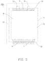
FIG. 5 is a schematic view of a fifth embodiment of an electrochemical energy storage device according to the present disclosure. -
FIG. 6 is a schematic view of a sixth embodiment of an electrochemical energy storage device according to the present disclosure. -
FIG. 7 is a schematic view of a seventh embodiment of an electrochemical energy storage device according to the present disclosure. -
FIG. 8 is a schematic view of an eighth embodiment of an electrochemical energy storage device according to the present disclosure. -
FIG. 9 is a schematic view of a ninth embodiment of an electrochemical energy storage device according to the present disclosure. -
FIG. 10 is a schematic view of a tenth embodiment of an electrochemical energy storage device according to the present disclosure. -
FIG. 11 is a schematic view of an eleventh embodiment of an electrochemical energy storage device according to the present disclosure. - Embodiments of the present application will be described in detail and examples of the embodiments will be illustrated in the drawings, where same or similar reference numerals are used to indicate same or similar elements or elements with same or similar functions. The embodiments described herein with reference to drawings are explanatory, illustrative, and used to generally understand the present application. The embodiments shall not be construed to limit the present application.
- The
electrochemical device 100 according to an embodiment of the present disclosure is described with reference to figures. - As shown in
FIG. 1 , the electrochemicalenergy storage device 100 includes ahousing 1 and abattery cell 3. Thehousing 1 includes afirst side wall 11, asecond side wall 12, and athird side wall 13, wherein thefirst side wall 11 and thesecond side wall 12 are opposite to each other, and thethird side wall 13 is adjacent to thesecond side wall 12. Thehousing 1 defines achamber 14 for receiving thebattery cell 3. Thechamber 14 is located between thefirst side wall 11 and thesecond side wall 12. At least one of thefirst side wall 11 and thesecond side wall 12 carries a reinforcinglayer 2. - The reinforcing
layer 2 improves the structural strength of thehousing 1. When the electrochemicalenergy storage device 100 is dropped or impacted, the reinforcinglayer 2 has a protective effect on thehousing 1, thereby avoiding a short circuit of the electrochemicalenergy storage device 100 or leakage of the electrolyte, thereby improving the safety and reliability of the electrochemicalenergy storage device 100. - In the related art, when an electrochemical energy storage device100 is dropped or impacted, the external impact force received by the electrochemical energy storage device is likely to crack or damage the housing, causing leakage of the electrolyte. The external impact force may also cause collision between the internal electrolyte and the housing, and collision between the electrode plate and the housing, which causes damage to the housing, thereby affecting the safety and reliability of the electrochemical energy storage device. In the present disclosure, by providing the reinforcing
layer 2 on at least one of thefirst side wall 11 and the second side wall, the structural strength of thehousing 1 is improved, so that the safety and reliability of the electrochemicalenergy storage device 100 are improved. - As shown in
FIG. 1 , the reinforcinglayer 2 is arranged on a surface of thefirst side wall 1 facing thechamber 14. Therefore, the structural strength of a side of thefirst side wall 11 close to thechamber 14 is increased, and the ability of thefirst side wall 11 to resist the impact of the electrolyte is reinforced. - As shown in
FIG. 1 , anelectrode tab 31 of thebattery cell 3 protrudes out of thechamber 14 from thefirst side wall 11, and the reinforcinglayer 2 is arranged on thesecond side wall 12. The reinforcinglayer 2 improves the structural strength of thesecond side wall 12 and prevents thesecond side wall 12 from cracking. In addition, the reinforcinglayer 2 is arranged on thesecond side wall 12, thus a receiving space for receiving the reinforcinglayer 2 is easier to design and manufacture, and a processing cost can be reduced. Preferably, the reinforcinglayer 2 defines a through hole for theelectrode tab 31 to pass through. - It should be understood that the
battery cell 3 includes electrode plates and separator. The electrode plates further include negative electrode plate and positive electrode plate, and the separator is located between the negative electrode plate and the positive electrode plate. The negative electrode plate, the separator, and the positive electrode plate are stacked or wound to form thebattery cell 3. Specifically, when manufacturing thebattery cell 3, first, a polyethylene porous film can be used as a substrate, and a fluffing agent can be used to perform a surface pretreatment on the substrate at a certain temperature to increase the surface tension of the substrate, and then the inorganic oxide (alumina, silica, etc.) and organic polymer (polyvinylidene fluoride) solutions are evenly coated on the surface of the substrate to obtain the separator. - Then, the positive electrode plate, the negative electrode plate, and the separator are wound in an order to form a bare cell. The bare cell and the electrolyte are built into the
housing 1, and the electrolyte is infiltrated into the bare cell to form thebattery cell 3. Finally, thebattery cell 3 is hot pressed to create a bonding between electrode plates and separator. - As shown in
FIG. 1 , the reinforcinglayer 2 is arranged on a surface of the second side wall close to thechamber 14. The structural strength of a side of thesecond side wall 12 close to thechamber 14 is improved by the reinforcinglayer 2, so that the ability of thesecond side wall 12 to resist the impact of the electrolyte is improved, thereby preventing the electrolyte from leaking. - As shown in
FIG. 1 , the reinforcinglayer 2 is arranged a surface of thesecond side wall 12 far away from thechamber 14. The structural strength of the outer surface of thesecond side wall 12 is enhanced by the reinforcinglayer 2, increasing the ability of thesecond side wall 12 to resist the external impact, thus cracks in thesecond side wall 12 can be avoided. - As shown in
FIG.1 , thehousing 1 includes thethird side wall 13, thethird side wall 13 is adjacent to thesecond side wall 12, and the reinforcinglayer 2 is arranged on a surface of thethird side wall 13 far away from thechamber 14. The reinforcinglayer 2 has a protective effect on thethird side wall 13 of thehousing 1. By providing the reinforcinglayer 2 on the surface of thethird side wall 13 away from theinner cavity 14, leakage of the electrolyte at thethird side wall 13 can be avoided, thereby the safety and reliability of the electrochemicalenergy storage device 100 can be further improved. - As shown in
FIG. 1 , thehousing 1 includes thefirst side wall 11, thesecond side wall 12, and twothird side walls 13. Thefirst side wall 11 and thesecond side wall 12 are opposite to each other, and the twothird side walls 13 are opposite to each other. An end of the left-handthird side wall 13 is connected to an end of thefirst side wall 11, other end of the left-handthird side wall 13 is connected to an end of thesecond side wall 12. An end of the right-hand side wall 13 is connected to other end of thefirst side wall 11, and other end of the right-hand side wall 13 is connected to other end of thesecond side wall 12. - The surface of the left-hand
third side wall 13 away from thechamber 14 and the surface of the right-hand side wall 13 away from thechamber 14 both carry the reinforcinglayer 2. - The structure of this embodiment is substantially the same as that of the first embodiment, the same elements are labeled by the same reference numerals, as shown in
FIG. 2 , except that the reinforcinglayer 2 is applied only to the surface of thefirst side wall 11 close to thechamber 14, the surface of thesecond side wall 12 close to thechamber 14, the surface of the left-hand side wall 13 away from thechamber 14, and the surface of the right-hand side wall 13 away from thechamber 14. - The structure of this embodiment is substantially the same as that of the first embodiment, in which the same elements are labeled by the same reference numerals, as shown in
FIG. 3 , except that the reinforcinglayer 2 is applied only to the surface of thefirst side wall 11 close to thechamber 14, the surface of thesecond side wall 12 close to thechamber 14, the surface of thesecond side wall 12 away from thechamber 14, and the surface of the left-hand side wall 13 away from thechamber 14. - The structure of this embodiment is substantially the same as that of the first embodiment, in which the same elements are labeled by the same reference numerals, as shown in
FIG. 4 , except that the reinforcinglayer 2 is applied only to the surface of thefirst side wall 11 close to thechamber 14, the surface of thefirst side wall 11 away from thechamber 14, the surface of thesecond side wall 12 close to thechamber 14, and the surface of thesecond side wall 12 away from thechamber 14. - The reinforcing
layer 2 is applied to the surface of thefirst side wall 11 away from thechamber 14, thus the structural strength of the outer surface of thefirst side wall 11 can be improved, and the ability of thefirst side wall 11 to resist the external impact can be improved. - The structure of this embodiment is substantially the same as that of the first embodiment, in which the same elements are labeled by the same reference numerals, as shown in
FIG. 5 , except that the reinforcinglayer 2 is applied only to the surface of thefirst side wall 11 close to thechamber 14, the surface of thesecond side wall 12 close to thechamber 14, and the surface of thesecond side wall 12 away from thechamber 14. - The structure of this embodiment is substantially the same as that of the first embodiment, in which the same elements are labeled by the same reference numerals, as shown in
FIG. 6 , except that the reinforcinglayer 2 is applied only to the surface of thefirst side wall 11 close to thechamber 14 and the surface of thesecond side wall 12 close to thechamber 14. - The structure of this embodiment is substantially the same as that of the first embodiment, in which the same elements are labeled by the same reference numerals, as shown in
FIG. 7 , except that the reinforcinglayer 2 is applied only to the surface of thesecond side wall 12 away from thechamber 14. - The structure of this embodiment is substantially the same as that of the first embodiment, in which the same elements are labeled by the same reference numerals, as shown in
FIG. 8 , except that the reinforcinglayer 2 is applied only to the surface of thefirst side wall 11 away from thechamber 14. - The structure of this embodiment is substantially the same as that of the first embodiment, in which the same elements are labeled by the same reference numerals, as shown in
FIG. 9 , except that the reinforcinglayer 2 is applied only to the surface of the left-handthird side wall 13 away from thechamber 14 and the surface of the right-handthird side wall 13 away from thechamber 14. - The structure of this embodiment is substantially the same as that of the first embodiment, in which the same elements are labeled by the same reference numerals, as shown in
FIG. 10 , except that the reinforcinglayer 2 is applied only to the surface of thesecond side wall 12 close to thechamber 14. - The structure of this embodiment is substantially the same as that of the first embodiment, in which the same elements are labeled by the same reference numerals, as shown in
FIG. 11 , except that the reinforcinglayer 2 is applied only to the surface of thefirst side wall 11 close to thechamber 14. - It is to be understood, reference throughout this specification to "an embodiment," "some embodiments," "an exemplary embodiment," "an example," "a specific example," or "some examples," means that a particular feature, structure, material, or characteristic described in connection with the embodiment or example is included in at least one embodiment or example of the present application. Thus, the appearances of these phrases throughout this specification do not necessarily refer to the same embodiment or example. Furthermore, the particular features, structures, materials, or characteristics may be combined in any suitable manner in one or more embodiments or examples.
- In addition, the above embodiments are exemplary, and the electrochemical
energy storage device 100 of this embodiment of the present disclosure also have the following features. - According to some embodiments of the present disclosure, the reinforcing
layer 2 is a polymer layer. The manufacturing process of the polymer layer is a mature technology, the manufacturing cost is low, the chemical properties of the polymer layer are relatively stable, it is generally resistant to acid and alkali corrosion, and the service life is long. - Alternatively, the polymer layer may be ethylene-acetic acid copolymer (EVA) hot-melt adhesive, polyamide (PA) hot-melt adhesive, polyurethane (PU) hot-melt adhesive, polyurethane, epoxy resin, polyacrylate, polyurea, or polycarbonate. Each of the ethylene-acetic acid copolymer (EVA) hot melt adhesive, polyamide (PA) hot melt adhesive, polyurethane (PU) hot melt adhesive, polyurethane, epoxy resin, polyacrylate, polyurea, and polycarbonate has strong stickiness after physical heating or chemical polymerizing. Specifically, the polymer layer may be one of the above materials, or a mixture of more materials thereof.
- In the physical heating process, the heating temperature is 60-160°C. Preferably, the heating temperature is 80-100°C, and the response time is 1-30 minutes. Preferably, the response time is 1-4 minutes.
- In the related art, when an electrochemical
energy storage device 100 is dropped or impacted, the electrode plates inside the electrochemical can slide against each other to cause an internal short circuit. In addition, the electrolyte of the electrochemical energy storage device can also impact the separator, and the separator easily shrinks to cause an internal short circuit. - As shown in
FIG. 1 , in an exemplary embodiment of the present disclosure, the surface of thefirst side wall 11 facing thechamber 14 is coated with bonding glue, forming the polymer layer on the surface of thefirst side wall 11 close to the chamber. By using the bonding force of the above polymer layer, the integrity of the electrode plates, the separator, and thehousing 1 is improved, and internal short circuit caused by sliding of the electrode plate relative to each other or the shrinkage of the separator is much less likely, thehousing 1 can also be prevented from cracking at the same time. - As shown in
FIG. 7 , in other exemplary embodiment of the present disclosure, the surface of thesecond side wall 12 facing thechamber 14 is coated with bonding glue, forming the polymer layer on the surface of thesecond side wall 12 facing thechamber 14. By using the bonding force of the above polymer layer, the integrity of the separator and thehousing 1 is improved, internal short circuit caused by the shrinkage of the separator is much less likely, and thehousing 1 can also be prevented from cracking at the same time. - In the related art, the electrochemical energy storage device further includes a working compartment, the housing is located in the working compartment. When the electrochemical energy storage device is dropped or impacted, a collision between the housing and the working compartment is likely, causing the housing to crack and break.
- As shown in
FIG. 3 , in an exemplary embodiment of the present disclosure, the surface of thethird side wall 13 away from thechamber 14 is coated with bonding glue, forming the polymer layer on the surface of thethird side wall 13 away from thechamber 14. By using the bonding force of the above polymer layer, the integrity of thehousing 1 and the working compartment is improved, and cracks of thehousing 1 caused by the collision between thehousing 1 and the working compartment are much less likely. - As shown in
FIG. 8 , in other exemplary embodiment of the present disclosure, the surface of thefirst side wall 11 away from thechamber 14 is coated with bonding glue, forming the polymer layer on the surface of thefirst side wall 11 away from thechamber 14. By using the bonding force of the above polymer layer, the integrity of thehousing 1 and the working compartment is improved, and cracks of thehousing 1 caused by the collision between thehousing 1 and the working compartment will not occur. - As shown in
FIG. 8 , in other exemplary embodiment of the present disclosure, the surface of thefirst side wall 11 away from thechamber 14 is coated with bonding glue, forming the polymer layer on the surface of thefirst side wall 11 away from thechamber 14. By using the bonding force of the above polymer layer, the integrity of thehousing 1 and the working compartment is improved, and cracks of thehousing 1 caused by the collision between thehousing 1 and the working compartment are prevented. - As shown in
FIG. 10 , in an exemplary embodiment of the present disclosure, the surface of thesecond side wall 12 away from thechamber 14 is coated with bonding glue, forming the polymer layer on the surface of thesecond side wall 12 away from thechamber 14. By using the bonding force of the above polymer layer, the integrity of thehousing 1 and the working compartment is improved, and cracks of thehousing 1 caused by the collision between thehousing 1 and the working compartment are prevented. - According to some embodiments of the present disclosure, the reinforcing layer is an adhesive tape. The adhesive paper has the advantages of simple structure, easy assembly, and low cost. Optionally, the adhesive tape may be single-sided adhesive tape or double-sided adhesive tape.
- In some embodiments of the present disclosure, the
battery cell 2 has a width of L1 (shown inFIGS. 6 and9 ), and the reinforcinglayer 2 has a length of L2 in the width direction of the battery cell 3 (shown inFIGS. 6 and9 ), wherein L2≥0.5L1. Therefore, the protective effect of the reinforcinglayer 2 on thehousing 1 is improved, and the reliability and safety of the electrochemicalenergy storage device 100 can be further improved. - For example, the length L2 of the reinforcing
layer 2 in the width direction of thebattery cell 3 canbe0.6L1, 0.7L1, 0.8L1, 0.9L1, or L1. Specifically, the length L2 of the reinforcinglayer 2 in the width direction of thebattery cell 3 can be designed and manufactured according to the model, size, and application environment of thebattery cell 3. - According to some embodiments of the present disclosure, the electrochemical
energy storage device 100 is a battery. Batteries are easy to carry and transport, the application environment of batteries is relatively diverse, and the demand for batteries is relatively wide. The battery may be a primary battery or a secondary battery. Of course, this disclosure is not limited to this, and the electrochemical energy storage device can also be a capacitor. - After the
battery cell 3 is assembled with thehousing 1, the processes of charge formation, negative pressure extraction, and capacity testing must be carried out, and then thehousing 1 with thebattery cell 3 can be placed in the working compartment, thereby completing the assembly of the electrochemicalenergy storage device 100. - Test experiments were performed on the electrochemical
energy storage devices 100 of a portion of the above examples and (comparative example 1) an energy storage device without thereinforcement layer 2 in the related art. The experimental conditions are as follows. The electrochemicalenergy storage device 100 of the above examples and the energy storage device without thereinforcement layer 2 in the related art is placed into a roller for testing, and the rotation speed of the roller is 3-4 circles/min, the height of the roller is 1m, and the roller rotates 250 circles for each experiment. The measured voltage and internal resistance are taken out at 75 circles, 150 circles, and 250 circles. After the drop is completed, thebattery cell 3 is taken out and placed at room temperature for 72 hours, and the voltage is measured every 24 hours. After 72h, the initial voltage is used as the reference, if the voltage drop of the electrochemicalenergy storage device 100 is less than 30mv, the electrochemical energy device is passed. Examination for cracking is carried out to count a cracking proportion. - The test results are shown in Table 1.
TABLE 1 Pass rate of voltage drop Cracking proportion Comparative example 1 10/20 18/20 Example 1 20/20 0/20 Example 2 20/20 2/20 Example 3 20/20 3/20 Example 4 20/20 0/20 Example 5 19/20 5/20 Example 6 18/20 18/20 Example 7 12/20 18/20 Example 8 11/20 7/20 - Research shows that the
reinforcement layer 2 being applied on the side of thefirst side wall 11 of thehousing 1 close to thechamber 14 significantly improves the pass rate in relation to voltage drop of the electrochemicalenergy storage device 100, and applying the reinforcinglayer 2 on the side of thefirst side wall 11, thesecond side wall 12, or thethird side wall 13 away from thechamber 14 significantly reduces the occurrence of cracks in the electrochemicalenergy storage device 100. - It is to be understood, even though information and advantages of the present embodiments have been set forth in the foregoing description, together with details of the structures and functions of the present embodiments, the disclosure is illustrative only; changes may be made within the principles of the present embodiments to the full extent indicated by the plain meaning of the terms in which the appended claims are expressed.
Claims (10)
- An electrochemical energy storage device characterized in that it comprises
a housing comprising a first side wall and a second side wall opposite to the first side wall, and defining a chamber configured for receiving a battery cell, the chamber being located between the first side wall and the second side wall;
wherein at least one of the first side wall and the second side wall is provided with a reinforcing layer. - The electrochemical energy storage device of claim 1, characterized in that the electrochemical energy storage device further comprises the battery cell, an electrode tab of the battery cell protruding out of the chamber from the first side wall, the reinforcing layer being on the second side wall.
- The electrochemical energy storage device of claim 2, characterized in that the reinforcing layer is disposed on a surface of the second side wall facing the chamber.
- The electrochemical energy storage device of claim 2, characterized in that the reinforcing layer is disposed on a surface of the second side wall away from the chamber.
- The electrochemical energy storage device of any one of claims 2-4, characterized in that the reinforcing layer is disposed on a surface of the first side wall away from the chamber.
- The electrochemical energy storage device of any one of claims 2-4, characterized in that the housing further comprises a third side wall, the third side wall is adjacent to the second side wall, the reinforcing layer is disposed on a surface of the third side wall away from the chamber.
- The electrochemical energy storage device of claim 1, characterized in that the reinforcing layer is a polymer layer.
- The electrochemical energy storage device of claim 1, characterized in that the reinforcing layer is an adhesive tape.
- The electrochemical energy storage device of claim 2, characterized in that the battery cell has a width of LI, the reinforcing layer has a length of L2 in the width direction of the battery cell, wherein L2≥0.5L1.
- The electrochemical energy storage device of claim 1, characterized in that the electrochemical energy storage device is a battery.
Applications Claiming Priority (2)
| Application Number | Priority Date | Filing Date | Title |
|---|---|---|---|
| CN201920325989.1U CN209487571U (en) | 2019-03-14 | 2019-03-14 | Electrochemical energy storage device |
| PCT/CN2020/079031 WO2020182191A1 (en) | 2019-03-14 | 2020-03-12 | Electrochemical energy storage device |
Publications (2)
| Publication Number | Publication Date |
|---|---|
| EP3731327A1 true EP3731327A1 (en) | 2020-10-28 |
| EP3731327A4 EP3731327A4 (en) | 2021-04-21 |
Family
ID=68134422
Family Applications (1)
| Application Number | Title | Priority Date | Filing Date |
|---|---|---|---|
| EP20712430.6A Pending EP3731327A4 (en) | 2019-03-14 | 2020-03-12 | DEVICE FOR ELECTROCHEMICAL ELECTRICITY STORAGE |
Country Status (5)
| Country | Link |
|---|---|
| US (1) | US20210218093A1 (en) |
| EP (1) | EP3731327A4 (en) |
| JP (1) | JP2021518032A (en) |
| CN (1) | CN209487571U (en) |
| WO (1) | WO2020182191A1 (en) |
Families Citing this family (3)
| Publication number | Priority date | Publication date | Assignee | Title |
|---|---|---|---|---|
| CN209487571U (en) * | 2019-03-14 | 2019-10-11 | 宁德新能源科技有限公司 | Electrochemical energy storage device |
| EP4131542A4 (en) * | 2020-03-30 | 2023-08-02 | Ningde Amperex Technology Ltd. | CELL AND BATTERY WITH THIS CELL |
| CN113097609B (en) * | 2021-03-30 | 2024-12-31 | 东莞新能安科技有限公司 | Electrochemical device and electronic device using the same |
Family Cites Families (18)
| Publication number | Priority date | Publication date | Assignee | Title |
|---|---|---|---|---|
| JP2003109667A (en) * | 2001-09-28 | 2003-04-11 | Mitsubishi Electric Corp | Non-aqueous electrolyte battery and method of manufacturing the same |
| KR100614373B1 (en) * | 2004-09-24 | 2006-08-21 | 삼성에스디아이 주식회사 | Lithium polymer battery having a strength reinforcing layer and a method of manufacturing the same |
| JP4793497B2 (en) * | 2010-03-12 | 2011-10-12 | ソニー株式会社 | Battery pack |
| CN102170019B (en) * | 2011-03-31 | 2017-02-08 | 东莞新能源电子科技有限公司 | Soft package lithium ion battery |
| JP5973765B2 (en) * | 2012-03-30 | 2016-08-23 | 積水化成品工業株式会社 | Interior materials for transport aircraft and installation methods for interior materials |
| PL2899769T3 (en) * | 2013-11-27 | 2019-09-30 | Lg Chem, Ltd. | Pouch for secondary battery and secondary battery comprising same |
| KR102248598B1 (en) * | 2014-02-05 | 2021-05-06 | 삼성에스디아이 주식회사 | Curved secondary battery and manufacturing method thereof |
| JP6109792B2 (en) * | 2014-08-06 | 2017-04-05 | 本田技研工業株式会社 | Battery pack and electric vehicle |
| CN107003251B (en) * | 2014-11-18 | 2020-08-28 | 三菱化学株式会社 | Method for repairing metal plate and method for manufacturing casting mold |
| KR101883536B1 (en) * | 2015-04-29 | 2018-07-30 | 주식회사 엘지화학 | Pouch type secondary battery and method of fabricating the same |
| CN107112470B (en) * | 2015-05-12 | 2020-04-03 | 奥林巴斯株式会社 | Battery packs for medical equipment and medical equipment units |
| WO2016192051A1 (en) * | 2015-06-03 | 2016-12-08 | 宁德新能源科技有限公司 | Electrochemical energy storage device |
| CN205050949U (en) * | 2015-10-20 | 2016-02-24 | 山东精工电子科技有限公司 | Lithium ion battery |
| CN205122651U (en) * | 2015-11-02 | 2016-03-30 | 宁德新能源科技有限公司 | Soft -packed lithium ion battery |
| JP2017222314A (en) * | 2016-06-17 | 2017-12-21 | 株式会社フジクラ | Car battery |
| CN108807809A (en) * | 2017-05-04 | 2018-11-13 | 宁德新能源科技有限公司 | Battery core and energy storage device |
| CN207705280U (en) * | 2017-07-29 | 2018-08-07 | 深圳格林德能源有限公司 | A kind of fire-retardant flexible packaging power battery structure |
| CN209487571U (en) * | 2019-03-14 | 2019-10-11 | 宁德新能源科技有限公司 | Electrochemical energy storage device |
-
2019
- 2019-03-14 CN CN201920325989.1U patent/CN209487571U/en active Active
-
2020
- 2020-03-12 EP EP20712430.6A patent/EP3731327A4/en active Pending
- 2020-03-12 WO PCT/CN2020/079031 patent/WO2020182191A1/en not_active Ceased
- 2020-03-12 US US16/955,248 patent/US20210218093A1/en not_active Abandoned
- 2020-03-12 JP JP2020517481A patent/JP2021518032A/en active Pending
Also Published As
| Publication number | Publication date |
|---|---|
| CN209487571U (en) | 2019-10-11 |
| EP3731327A4 (en) | 2021-04-21 |
| US20210218093A1 (en) | 2021-07-15 |
| JP2021518032A (en) | 2021-07-29 |
| WO2020182191A1 (en) | 2020-09-17 |
Similar Documents
| Publication | Publication Date | Title |
|---|---|---|
| EP2869363B1 (en) | Separator, and electrochemical device comprising same | |
| EP3751658B1 (en) | Stack type electrode assembly in which bending phenomenon is alleviated, and manufacturing method therefor | |
| KR101187767B1 (en) | A separator and electrochemical device containing the same | |
| ES2931901T3 (en) | electrode assembly | |
| EP3731327A1 (en) | Electrochemical energy storage device | |
| KR101913383B1 (en) | Electrochemical energy storage device | |
| US20240222748A1 (en) | All solid secondary battery, all solid secondary battery structure and preparation method for all solid secondary battery | |
| WO2009123218A1 (en) | Cell separator and cell using the same | |
| WO2025002220A9 (en) | Secondary battery and electronic device | |
| KR101898351B1 (en) | Battery | |
| EP4228063A1 (en) | Electrochemical device and electronic device | |
| KR102857598B1 (en) | Electrode-assembly and manufacturing method thereof | |
| CN116345070A (en) | A kind of secondary battery and its preparation method, electronic device | |
| KR101060378B1 (en) | Lithium polymer secondary battery packaging material and manufacturing method thereof | |
| CN222088672U (en) | Lithium ion battery | |
| CN107611321A (en) | Barrier film and secondary cell | |
| CN117276764A (en) | Secondary batteries and electronic equipment | |
| CN119627370B (en) | Battery and battery pack | |
| CN121307234A (en) | A type of battery | |
| CN221727209U (en) | Lithium ion battery | |
| US20260128487A1 (en) | Secondary battery and electronic device | |
| CN111106303A (en) | Preparation method of nickel tab with heat-resistant insulating coating | |
| CN120963178A (en) | Flexible aluminum-plastic film and its applications | |
| CN121282500A (en) | Battery and electric equipment | |
| CN120184467A (en) | Secondary batteries and electrical equipment |
Legal Events
| Date | Code | Title | Description |
|---|---|---|---|
| STAA | Information on the status of an ep patent application or granted ep patent |
Free format text: STATUS: UNKNOWN |
|
| STAA | Information on the status of an ep patent application or granted ep patent |
Free format text: STATUS: THE INTERNATIONAL PUBLICATION HAS BEEN MADE |
|
| PUAI | Public reference made under article 153(3) epc to a published international application that has entered the european phase |
Free format text: ORIGINAL CODE: 0009012 |
|
| STAA | Information on the status of an ep patent application or granted ep patent |
Free format text: STATUS: REQUEST FOR EXAMINATION WAS MADE |
|
| 17P | Request for examination filed |
Effective date: 20200330 |
|
| AK | Designated contracting states |
Kind code of ref document: A1 Designated state(s): AL AT BE BG CH CY CZ DE DK EE ES FI FR GB GR HR HU IE IS IT LI LT LU LV MC MK MT NL NO PL PT RO RS SE SI SK SM TR |
|
| AX | Request for extension of the european patent |
Extension state: BA ME |
|
| RIN1 | Information on inventor provided before grant (corrected) |
Inventor name: QI, WEI Inventor name: WANG, ZHONGXU Inventor name: WANG, XIAOYING Inventor name: WANG, YING |
|
| A4 | Supplementary search report drawn up and despatched |
Effective date: 20210319 |
|
| RIC1 | Information provided on ipc code assigned before grant |
Ipc: H01M 10/0525 20100101AFI20210315BHEP Ipc: H01M 50/10 20210101ALI20210315BHEP Ipc: H01M 50/103 20210101ALI20210315BHEP Ipc: H01M 50/105 20210101ALI20210315BHEP Ipc: H01M 50/14 20210101ALI20210315BHEP Ipc: H01M 50/186 20210101ALI20210315BHEP Ipc: H01M 50/197 20210101ALI20210315BHEP Ipc: H01M 50/198 20210101ALI20210315BHEP |
|
| DAV | Request for validation of the european patent (deleted) | ||
| DAX | Request for extension of the european patent (deleted) | ||
| STAA | Information on the status of an ep patent application or granted ep patent |
Free format text: STATUS: EXAMINATION IS IN PROGRESS |
|
| 17Q | First examination report despatched |
Effective date: 20250116 |