EP3731130A1 - Apparatus for determining an occupancy map - Google Patents
Apparatus for determining an occupancy map Download PDFInfo
- Publication number
- EP3731130A1 EP3731130A1 EP19170527.6A EP19170527A EP3731130A1 EP 3731130 A1 EP3731130 A1 EP 3731130A1 EP 19170527 A EP19170527 A EP 19170527A EP 3731130 A1 EP3731130 A1 EP 3731130A1
- Authority
- EP
- European Patent Office
- Prior art keywords
- area
- sub
- free
- processing unit
- location
- Prior art date
- Legal status (The legal status is an assumption and is not a legal conclusion. Google has not performed a legal analysis and makes no representation as to the accuracy of the status listed.)
- Granted
Links
Images



Classifications
-
- G—PHYSICS
- G06—COMPUTING OR CALCULATING; COUNTING
- G06V—IMAGE OR VIDEO RECOGNITION OR UNDERSTANDING
- G06V20/00—Scenes; Scene-specific elements
-
- G—PHYSICS
- G06—COMPUTING OR CALCULATING; COUNTING
- G06F—ELECTRIC DIGITAL DATA PROCESSING
- G06F18/00—Pattern recognition
- G06F18/20—Analysing
- G06F18/25—Fusion techniques
Definitions
- occupancy maps in 3D or 2D, are then used as ground truth for comparing and evaluate ADAS algorithms, which reconstruct 3D information based on images, for example Structure From Motion (SFM), Geometric Depth Reconstruction (GDR). Scores obtained from such comparison (called KPI) can be useful information for two reasons: to compare alternative algorithms or versions of the same one; indicate the performance of algorithms.
- SFM Structure From Motion
- GDR Geometric Depth Reconstruction
- the processing unit is configured to process the second dataset to determine a second free sub-area.
- the second free sub-area comprises an area within a second plurality of lines extending from the second location that are different to the second plurality of subtending lines and comprises an area within the second plurality of subtending lines between the second location and the object.
- the processing unit is configured to process the second dataset to determine a second object sub-extent of the object subtended by the second plurality of subtending lines.
- the plurality of datasets comprises 2D information.
- the processing unit is configured to utilize the plurality of datasets and associated plurality of locations of the sensor to iteratively update the free area, the outer extent of the object and the unknown area comprising utilization of associated determined free sub-areas, and object sub-extents for each of the plurality of datasets acquired and associated plurality of locations.
- the apparatus for determining an occupancy map comprises an input unit, and a processing unit.
- the input unit is configured to provide the processing unit with a plurality of datasets of an object.
- the plurality of datasets has been acquired by a sensor positioned at a plurality of different locations, and each individual dataset was acquired at a different location.
- Data in each of the plurality of datasets comprises distance information from the sensor to the object.
- For a first location of the sensor the object is subtended by a first plurality of subtending lines extending from the first location to and through the object, and for the first location a first dataset was acquired.
- the front surface of the object can be seen, which could be a real 3D surface or that 3D surface projected in a top down manner into a 2D area.
- this region is the first object sub-extent, and can be a straight or curved line with no thickness or a straight or curved line with a thickness and as such be an actual area.
- the processing unit is configured also to process the first dataset to determine an unknown area comprising a first unknown sub-area as an area other than the first free sub-area and the first object sub-extent. Referring to Fig. 2a and Figs.
- an area of the occupancy map is re-qualified as a dynamic object area.
- 2D information can itself be acquired, via for example a simple radar sensor that gives a single distance for each angular line of sight in the horizontal plane.
- the occupancy map has i) increased the size because the position of the sensor has changed, so the maximum range is outside the current map; and ii) has updated its areas, and now can contains 4 different classes: occupied, dynamically occupied, free, and unknown.
Landscapes
- Engineering & Computer Science (AREA)
- Theoretical Computer Science (AREA)
- Physics & Mathematics (AREA)
- General Physics & Mathematics (AREA)
- Multimedia (AREA)
- Data Mining & Analysis (AREA)
- Bioinformatics & Cheminformatics (AREA)
- Artificial Intelligence (AREA)
- Life Sciences & Earth Sciences (AREA)
- Bioinformatics & Computational Biology (AREA)
- Computer Vision & Pattern Recognition (AREA)
- Evolutionary Biology (AREA)
- Evolutionary Computation (AREA)
- General Engineering & Computer Science (AREA)
- Traffic Control Systems (AREA)
- Optical Radar Systems And Details Thereof (AREA)
- Radar Systems Or Details Thereof (AREA)
Abstract
Description
- The present invention relates to an apparatus for determining an occupancy map, a system for determining an occupancy map, a method for determining an occupancy map, as well as to a computer program element and a computer readable medium.
- The general background of this invention is the field of advanced driving assistance systems and their development.
- Lidars or other depth sensors (ultrasonic, radars, stereo vision, etc) are used for capturing the surrounding scenario as a point cloud. With consecutive captures, from several points of view (when the sensor is in a mobile platform, such a car, with a location system, such odometry, all the point clouds are accumulated knowing the motion of the mobile platform and merged into just one
occupancy 3D map. Usually this 3D map is reduced into a TOP-down projection or binary occupancy map, termed a 2D map. Some of the depth sensors have no vertical resolution, so they are 2D depth sensors instead of 3D, for example a 2D laser scanner, or ultrasonic scanner. These occupancy maps, in 3D or 2D, are then used as ground truth for comparing and evaluate ADAS algorithms, which reconstruct 3D information based on images, for example Structure From Motion (SFM), Geometric Depth Reconstruction (GDR). Scores obtained from such comparison (called KPI) can be useful information for two reasons: to compare alternative algorithms or versions of the same one; indicate the performance of algorithms. - However, occupancy maps generated by depth sensors, both 3D and 2D, do not contain enough information to be considered as an accurate ground truth data for the evaluation of such algorithms.
- There is a need to address this issue.
- The object of the present invention is solved with the subject matter of the independent claims, wherein further embodiments are incorporated in the dependent claims.
- In a first aspect, there is provided an apparatus for determining an occupancy map, comprising:
- an input unit; and
- a processing unit
- The input unit is configured to provide the processing unit with a plurality of datasets of an object. The plurality of datasets was acquired by a sensor positioned at a plurality of different locations. Each dataset was acquired at a different location. Data in each of the plurality of datasets comprises distance information from the sensor to the object. For a first location of the sensor the object is subtended by a first plurality of subtending lines extending from the first location to and through the object. For the first location a first dataset was acquired. The processing unit is configured to process the first dataset to determine a free area comprising a first free sub-area. The first free sub-area comprises an area within a first plurality of lines extending from the first location that are different to the first plurality of subtending lines and comprises an area within the first plurality of subtending lines between the first location and the object. The processing unit is configured to process the first dataset to determine an outer extent of the object that surrounds an object area, the outer extent of the object comprising a first object sub-extent of the object subtended by the first plurality of subtending lines. The processing unit is configured to process the first dataset to determine an unknown area comprising a first unknown sub-area as an area other than the first free sub-area and the first object sub-extent. For a second location of the sensor the object is subtended by a second plurality of subtending lines extending from the second location to and through the object, and wherein for the second location a second dataset was acquired. The processing unit is configured to process the second dataset to determine a second free sub-area. The second free sub-area comprises an area within a second plurality of lines extending from the second location that are different to the second plurality of subtending lines and comprises an area within the second plurality of subtending lines between the second location and the object. The processing unit is configured to process the second dataset to determine a second object sub-extent of the object subtended by the second plurality of subtending lines. The processing unit is configured to process the second dataset to determine a second unknown sub-area as an area other than the second free sub-area and the second object sub-extent. The processing unit is configured to determine an updated free area, an updated outer extent of the object, and an updated unknown area. The updated free area is determined as an area that is covered by the first free sub-area and the second free sub-area. The updated outer extent of the object comprises the first object sub-extent and the second object sub-extent. The updated unknown area is determined as an area other than the updated free area and the updated outer extent of the object. The processing unit is configured to generate an occupancy map comprising utilization of the updated free area, the updated outer extent of the object and the updated unknown area.
- In this manner, an improved occupancy map can be determined for the evaluation of algorithms utilized for example in advanced driving assistance systems. This is because, the object space is better characterised in terms of where the object is located, where it is not located, and areas where it is not known if the object is located or is not located.
- In other words, an object is viewed from a first position and only the front surface of the object can be seen, but the distances to the object are known. A free area is then formed from an area in front of the object and the areas to the sides of the object (all the lines of sight that do not intersect with the object) and this is termed a first free sub-area. The area behind the object is unknown. Then, this process is repeated when the object is viewed from a different position and a second free sub-area is determined in the same way as for the first free sub-area, and similarly the front surface of the object is also known and the unknown area is again behind the object. Then this information can be combined to reduce the unknown areas, and determine what is free area and what area is bounded by the outer surface of the object - the object area.
- In an example, the orientation of the sensor for each of the locations is known with respect to the orientations at the other locations, and the relative translation from one location to the next location is known.
- In an example, the processing unit is configured to determine a dynamic object area to account for movement of the object; and wherein the processing unit is configured to generate the occupancy map comprising utilization of the dynamic object area.
- In this manner, an occupancy map for the testing and evaluation of ADAS algorithms, for example, is further improved because information is provided that accounts for movement of the object. Thus, existing occupancy maps can indicate that parts of an object are at two locations, whereas the object has actually moved during sensor data acquisition to build the occupancy map. However, in the past an ADAS algorithm tested on this data would lead to an incorrect evaluation because it could indicate that there is no object located at a position when the object was there but has moved. Thus now, in providing a further qualified region of space, that being dynamic object space, algorithm testing and evaluation can take this into account during performance testing.
- In an example, the dynamic object area comprises an area that is a sub-set of the first object sub-extent and is a sub-set of the second free sub-area.
- In other words, the object between acquisition of the first dataset and the second dataset has moved, and the region that was a free area and that is now occupied by the object is now termed a dynamic object area.
- In an example, the dynamic object area comprises an area that is a sub-set of the first free sub-area and is a sub-set of the second object sub-extent.
- In an example, the plurality of datasets comprises 3D information.
- In an example, the processing unit is configured to pre-process the 3D information to determine projected 2D information.
- In other words, either 3D information can be used, as would be viewed by a human, or that 3D information can be transformed for example into a top-down 2D projection.
- In an example, the plurality of datasets comprises 2D information.
- In an example, the processing unit is configured to utilize the plurality of datasets and associated plurality of locations of the sensor to iteratively update the free area, the outer extent of the object and the unknown area comprising utilization of associated determined free sub-areas, and object sub-extents for each of the plurality of datasets acquired and associated plurality of locations.
- In an example, the processing unit is configured to iteratively update the dynamic object area.
- In a second aspect, there is provided a system for determining an occupancy map, comprising:
- a sensor;
- an apparatus for determining an occupancy map according to the first aspect; and
- an output unit.
- The sensor is configured to acquire the plurality of data sets. The output unit is configured to output the occupancy map.
- In a third aspect, there is provided a method for determining an occupancy map, comprising:
- a) acquiring by a sensor positioned at a plurality of different locations a plurality of datasets of an object, wherein each dataset is acquired at a different location, wherein data in each of the plurality of datasets comprises distance information from the sensor to the object;
- b) providing a processing unit with a plurality of datasets of the object;
wherein for a first location of the sensor the object is subtended by a first plurality of subtending lines extending from the first location to and through the object, and wherein for the first location a first dataset was acquired, and wherein the method comprises: - c) processing by the processing unit the first dataset to determine a free area comprising a first free sub-area, wherein the first free sub-area comprises an area within a first plurality of lines extending from the first location that are different to the first plurality of subtending lines and comprises an area within the first plurality of subtending lines between the first location and the object;
- d) processing by the processing unit the first dataset to determine an outer extent of the object that surrounds an object area, the outer extent of the object comprising a first object sub-extent of the object subtended by the first plurality of subtending lines;
- e) processing by the processing unit the first dataset to determine an unknown area comprising a first unknown sub-area as an area other than the first free sub-area and the first object sub-extent;
wherein, for a second location of the sensor the object is subtended by a second plurality of subtending lines extending from the second location to and through the object, and wherein for the second location a second dataset was acquired, and wherein the method comprises: - f) processing by the processing unit the second dataset to determine a second free sub-area, wherein the second free sub-area comprises an area within a second plurality of lines extending from the second location that are different to the second plurality of subtending lines and comprises an area within the second plurality of subtending lines between the second location and the object;
- g) processing by the processing unit the second dataset to determine a second object sub-extent of the object subtended by the second plurality of subtending lines;
- h) processing by the processing unit the second dataset to determine a second unknown sub-area as an area other than the second free sub-area and the second object sub-extent;
- i) determining by the processing unit an updated free area as an area that is covered by the first free sub-area and the second free sub-area;
- j) determining by the processing unit updated outer extent of the object as an area that comprises the first object sub-extent and the second object sub-extent;
- k) determining by the processing area an updated unknown area as an area other than the updated free area and the updated outer extent of the object; and
- m) generating by the processing unit an occupancy map utilizing the updated free area, the updated outer extent of the object and the updated unknown area.
- In an example, the method comprises utilizing the plurality of datasets and associated plurality of locations of the sensor to iteratively update the free area, the outer extent of the object and the unknown area comprising utilization of associated determined free sub-areas, and object sub-extents for each of the plurality of datasets acquired and associated plurality of locations.
- In an example, the method comprises iteratively updating the dynamic object area.
- According to another aspect, there is provided a computer program element controlling apparatus as previously described which, when the computer program element is executed by a processing unit, is adapted to perform the method steps as previously described.
- According to another aspect, there is also provided a computer readable medium having stored the computer element as previously described.
- Advantageously, the benefits provided by any of the above aspects equally apply to all of the other aspects and vice versa.
- The above aspects and examples will become apparent from and be elucidated with reference to the embodiments described hereinafter.
- Exemplary embodiments will be described in the following with reference to the following drawings:
-
Fig. 1 shows an example of determination of an occupancy map; -
Fig. 2 shows an example of steps in the determination of the occupancy map ofFig. 1 ; -
Fig. 3 shows an example of part of a step in the determination of an occupancy map; and -
Fig. 4 shows an example of 3D data being transformed into 2D data. -
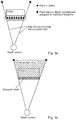
Figs. 1-4 relate to an apparatus, system and method for determining an occupancy map. In an example, the apparatus for determining an occupancy map comprises an input unit, and a processing unit. The input unit is configured to provide the processing unit with a plurality of datasets of an object. The plurality of datasets has been acquired by a sensor positioned at a plurality of different locations, and each individual dataset was acquired at a different location. Data in each of the plurality of datasets comprises distance information from the sensor to the object. For a first location of the sensor the object is subtended by a first plurality of subtending lines extending from the first location to and through the object, and for the first location a first dataset was acquired. The processing unit is configured to process the first dataset to determine a free area comprising a first free sub-area. The first free sub-area comprises an area within a first plurality of lines extending from the first location that are different to the first plurality of subtending lines and comprises an area within the first plurality of subtending lines between the first location and the object. Thus, referring toFig. 2a the first free sub-area is the area in the triangle extending from the sensor position to the front corners of the object in front of the object and the areas either side of the triangle. The processing unit is configured also to process the first dataset to determine an outer extent of the object that surrounds an object area, the outer extent of the object comprising a first object sub-extent of the object subtended by the first plurality of subtending lines. Thus, as shown inFig. 2a and inFigs. 3a and 3b , only the front surface of the object can be seen, which could be a real 3D surface or that 3D surface projected in a top down manner into a 2D area. However, this region is the first object sub-extent, and can be a straight or curved line with no thickness or a straight or curved line with a thickness and as such be an actual area. The processing unit is configured also to process the first dataset to determine an unknown area comprising a first unknown sub-area as an area other than the first free sub-area and the first object sub-extent. Referring toFig. 2a andFigs. 3a and 3b , this is the area in the triangle extending from the sensor to the corners of the object that is behind the front surface/area (the first object sub-extent) and that the sensor cannot see. The object is actually a rectangle in this example, but from the data acquired by the sensor from the first location this cannot be determined, and thus the area that is behind the first object sub-extent is allocated as a first unknown sub-area. For a second location of the sensor the object is subtended by a second plurality of subtending lines extending from the second location to and through the object, and for the second location a second dataset was acquired. This is for example shown inFig. 2b . The processing unit is configured to process the second dataset to determine a second free sub-area. The second free sub-area comprises an area within a second plurality of lines extending from the second location that are different to the second plurality of subtending lines and comprises an area within the second plurality of subtending lines between the second location and the object. Thus, referring toFig. 2b the second free sub-area is the area in the "triangle" extending from the sensor position to the bottom left corner of the object to the corner facing the sensor and to the top right corner of the object that is in front of the object and the areas either side of the triangle. The processing unit is configured to process the second dataset to determine a second object sub-extent of the object subtended by the second plurality of subtending lines. Referring toFig. 2b this is the bottom surface/area of the object (the first object sub-extent) and the side surface area of the object - in this example, and the second object sub-extent need not include the first object sub-extent and for example the second sensor acquisition could have been that as shown inFig. 2c . The processing unit is configured to process the second dataset to determine a second unknown sub-area as an area other than the second free sub-area and the second object sub-extent. Again, this is everything behind the object that cannot be seen, and is not actually shown in the figures for the second acquisition, but is in effect as shown inFig. 2a but for the position ofFig. 2b . The processing unit is configured to determine an updated free area, an updated outer extent of the object, and an updated unknown area. The updated free area is determined as an area that is covered by the first free sub-area and the second free sub-area. This is shown inFig. 2b , where an area that was an unknown area has now become a free area in addition to what was already known to be a free area - this extra part of the free area is termed the "previously unknown area" inFig. 2b . The updated outer extent of the object comprises the first object sub-extent and the second object sub-extent. The updated unknown area is determined as an area other than the updated free area and the updated outer extent of the object. This is shown inFig. 2b as the "unknown area". The processing unit is configured to generate an occupancy map comprising utilization of the updated free area, the updated outer extent of the object and the updated unknown area. - According to an example, the orientation of the sensor for each of the locations is known with respect to the orientations at the other locations, and the relative translation from one location to the next location is known.
- According to an example, the processing unit is configured to determine a dynamic object area to account for movement of the object; and wherein the processing unit is configured to generate the occupancy map comprising utilization of the dynamic object area.
- According to an example, the dynamic object area comprises an area that is a sub-set of the first object sub-extent and is a sub-set of the second free sub-area.
- In an example, an area of the occupancy map is re-qualified as a dynamic object area.
- According to an example, the dynamic object area comprises an area that is a sub-set of the first free sub-area and is a sub-set of the second object sub-extent.
- In an example, an area of the occupancy map is re-qualified as a dynamic object area.
- According to an example, the plurality of datasets comprises 3D information.
- According to an example, the processing unit is configured to pre-process the 3D information to determine projected 2D information. This is shown in
Fig. 4 and explained in more detail below. - According to an example, the plurality of datasets comprises 2D information.
- In an example, the sensor is one of: a laser sensor, a radar sensor, an ultrasonic sensor, a stereo vision sensor.
- Thus, 2D information can itself be acquired, via for example a simple radar sensor that gives a single distance for each angular line of sight in the horizontal plane.
- According to an example, the processing unit is configured to utilize the plurality of datasets and associated plurality of locations of the sensor to iteratively update the free area, the outer extent of the object and the unknown area comprising utilization of associated determined free sub-areas, and object sub-extents for each of the plurality of datasets acquired and associated plurality of locations. This is shown in
Figs. 2a-2d , where the outer extent of the object need not be completely closed (or can be completely) and can have an unknown area in the middle, because that area is never actually sensed. - According to an example, the processing unit is configured to iteratively update the dynamic object area.
- Thus, the apparatus can operate in an offline mode, and utilize sensor data to determine the occupancy map.
- However, a system for determining an occupancy map can include a sensor, and the apparatus for determining an occupancy map as described above; and also have an output unit. The sensor is configured to acquire the plurality of data sets, and the output unit is configured to output the occupancy map.
- Also, an example relates to a method for determining an occupancy map, comprising:
- a) acquiring by a sensor positioned at a plurality of different locations a plurality of datasets of an object, wherein each dataset is acquired at a different location, wherein data in each of the plurality of datasets comprises distance information from the sensor to the object;
- b) providing a processing unit with a plurality of datasets of the object;
wherein for a first location of the sensor the object is subtended by a first plurality of subtending lines extending from the first location to and through the object, and wherein for the first location a first dataset was acquired, and wherein the method comprises: - c) processing by the processing unit the first dataset to determine a free area comprising a first free sub-area, wherein the first free sub-area comprises an area within a first plurality of lines extending from the first location that are different to the first plurality of subtending lines and comprises an area within the first plurality of subtending lines between the first location and the object;
- d) processing by the processing unit the first dataset to determine an outer extent of the object that surrounds an object area, the outer extent of the object comprising a first object sub-extent of the object subtended by the first plurality of subtending lines;
- e) processing by the processing unit the first dataset to determine an unknown area comprising a first unknown sub-area as an area other than the first free sub-area and the first object sub-extent;
wherein, for a second location of the sensor the object is subtended by a second plurality of subtending lines extending from the second location to and through the object, and wherein for the second location a second dataset was acquired, and wherein the method comprises: - f) processing by the processing unit the second dataset to determine a second free sub-area, wherein the second free sub-area comprises an area within a second plurality of lines extending from the second location that are different to the second plurality of subtending lines and comprises an area within the second plurality of subtending lines between the second location and the object;
- g) processing by the processing unit the second dataset to determine a second object sub-extent of the object subtended by the second plurality of subtending lines;
- h) processing by the processing unit the second dataset to determine a second unknown sub-area as an area other than the second free sub-area and the second object sub-extent;
- i) determining by the processing unit an updated free area as an area that is covered by the first free sub-area and the second free sub-area;
- j) determining by the processing unit updated outer extent of the object as an area that comprises the first object sub-extent and the second object sub-extent;
- k) determining by the processing area an updated unknown area as an area other than the updated free area and the updated outer extent of the object; and
- m) generating by the processing unit an occupancy map utilizing the updated free area, the updated outer extent of the object and the updated unknown area.
- In an example, in step a) the orientation of the sensor for each of the locations is known with respect to the orientations at the other locations, and wherein the relative translation from one location to the next location is known.
- In an example, the method comprises step l) determining by the processing unit a dynamic object area to account for movement of the object; and wherein step m) comprises generating the occupancy map comprising utilization of the dynamic object area.
- In an example, the dynamic object area comprises an area that is a sub-set of the first object sub-extent and is a sub-set of the second free sub-area.
- In an example, the dynamic object area comprises an area that is a sub-set of the first free sub-area and is a sub-set of the second object sub-extent.
- In an example, the plurality of datasets comprises 3D information.
- In an example, the processing unit is configured to pre-process the 3D information to determine projected 2D information.
- In an example, the plurality of datasets comprises 2D information.
- In an example, the sensor is one of: a laser sensor, a radar sensor, an ultrasonic sensor, a stereo vision sensor.
- According to an example, the method comprises utilizing the plurality of datasets and associated plurality of locations of the sensor to iteratively update the free area, the outer extent of the object and the unknown area comprising utilization of associated determined free sub-areas, and object sub-extents for each of the plurality of datasets acquired and associated plurality of locations.
- According to an example, the method comprises iteratively updating the dynamic object area.
- Thus, the present system solves problems such as:
Maps generated by depth sensors, both 3D and 2D, have not until now contained enough information to be considered as accurate ground truth data for evaluation of ADAS algorithms. Specifically, in known techniques to determine occupancy maps, depth points detected by the sensor can be represented as an occupied area on a non-represented background, which is considered as unknown space. In particular since the maps, both 3D and 2D, represent only seen points, which belong to occupied space, then the background or non-represented area is the second area class, which represent free space and unseen space in the same way. When an ADAS algorithm contains a 3D point corresponding to a non-represented area in the ground truth map, then the point is incorrectly evaluated, because that area could be both free or unknown. The occupancy maps are built merging consecutive captures, and as such objects can move between two captures (termed, dynamic objects). Thus, in existing techniques to determine occupancy maps, the dynamic object is represented as points in the final occupancy map. Therefore, when an ADAS algorithm does not produce a 3D point in the dynamic area, the area is incorrectly evaluating by the algorithm as a false negative, that is, it was expected that a point should be in that area. In other words, existing techniques of determining occupancy maps are incorrectly determining the object as being too large, as it exists at all positions in time, when actually it has moved. Thus, it is only an occupied area, that is only a small subset of the whole captured scenario, that can be used as ground truth, and the non-represented area (which usually is the biggest part of the scenario) cannot be used. Because of this missed usage of the captured information, the evaluation of ADAS algorithms, in terms of score, KPI, or any metric, may show lower performance than it should. Thus, the apparatus, system and method for determining an occupancy map addresses these issues, by separating unknown from free space, and separating occupied (object area) from dynamically occupied dynamic object area) space. - Thus, as seen from
Figs. 1-4 , based on ray tracing of the multi-beam lidar, or the trajectory of each beam in any depth sensor, the 2D mapping reduces the boundaries of the non-represented area iteratively through consecutive captures taken from different poses (position and orientation) of the sensor. The result is a 2D occupancy map. which is not binary as for known techniques to determine occupancy maps that only have occupied and unknown areas, but contains four area classes: occupied, dynamically occupied, free, and unknown. - In a detailed embodiment, the method starts with an empty 2D map, where all is unknown, and has 4 steps:
- A capture is taken from the sensor in a different position from the previous one. If it is a 3D sensor then the point cloud is transformed into a top-down projection, as shown in
Fig. 4 . This is done by keeping only the 3D points inside the obstacle area, which is defined with a minimum and maximum height. Then these points remove its height coordinate, so they are projected into the ground with height equal to zero. Otherwise, if it is a 2D depth sensor, the top-down projection is already obtained by default. The 2D top-down projection represents separated points, and they are merged into clusters (shapes, polygons around the points), as shown inFigs. 3a and 3b . The occupied area is composed by joining all points detected if they are closer than a distance threshold, which is a parameter depending on the horizontal resolution of the depth sensor. For example, if two points are closer than 2 cm, then they compose into a line of occupied area between both of them. The unknown area is composed taking into account the region behind the occupied area limited by the two rays tracing that includes the occupied area but have a very different distance detected (for example infinite if they detect no object) - these are the extreme sides of the triangle shown infigs. 3a and 3b . The result of this stage is a 2D plane with areas, instead of points, which are occupied (because there is an object returning some distance from the sensor). - Based on the current position of the sensor, two ray traces can be projected onto the capture from that position until the maximum range of the sensor, passing through the two extreme points of the occupied area. In this way, the occupied area is completely inside the two rays. The result of this stage is a division of the circular capture:
- the section between the two rays, and the section outside.
- the section inside is divided by the occupied area, in the area in front of it, and the area behind it.
- The non-represented area of the capture (what is not occupied area) within the maximum range of the sensor is classified into free or unknown areas, apart from the occupied area which is already defined by the capture. It is free area outside the two rays trajectories, and also the part which is inside and between the sensor and the occupied area. It is unknown area within the two rays, but behind the occupied area. As a result of this stage, the capture contains now 3 different classes areas: occupied area, free area, and unknown area.
- The classified capture is integrated into the current map by accumulating information and overlapping areas. If an unknown area in the map receives from the capture an occupied area in the same position, then the map in that area becomes occupied. If an unknown area in the map receives from the capture a free area in the same position, then the map in that area becomes free. If an occupied area in the map receives from the capture a free area in the same position, then the map in that area becomes dynamically occupied. If a free area in the map receives from the capture an occupied area in the same position, then the map in that area becomes dynamically occupied. For any other combination, the processing unit is not changing the status in that area.
- As a result of this stage, the occupancy map has i) increased the size because the position of the sensor has changed, so the maximum range is outside the current map; and ii) has updated its areas, and now can contains 4 different classes: occupied, dynamically occupied, free, and unknown.
- These steps are repeated if new captures are received.
- In this way, the 2D occupancy map contains more information, instead of having occupied versus non-represented space (binary), now it contains four classes: occupied, dynamically occupied, free, and unknown space. The free space is separated from unknown space, and dynamic objects are separated from static occupied spaces. As a 2D occupancy Map is generated, the size of the data is low, and is easy to store and process (for example, in embedded systems). The 2D Map occupancy map determined contains a smaller unknown area than existing methods. The occupancy man is richer in information with respect to ground truth, and therefore provides for more accurate performance KPI assessment and evaluation of ADAS algorithms.
- In another exemplary embodiment, a computer program or computer program element is provided that is characterized by being configured to execute the method steps of the method according to one of the preceding embodiments, on an appropriate system.
- The computer program element might therefore be stored on a computer unit, which might also be part of an embodiment. This computing unit may be configured to perform or induce performing of the steps of the method described above. Moreover, it may be configured to operate the components of the above described apparatus and/or system. The computing unit can be configured to operate automatically and/or to execute the orders of a user. A computer program may be loaded into a working memory of a data processor. The data processor may thus be equipped to carry out the method according to one of the preceding embodiments.
- According to a further exemplary embodiment of the present invention, a computer readable medium, such as a CD-ROM, is presented wherein the computer readable medium has a computer program element stored on it which computer program element is described by the preceding section.
- It has to be noted that embodiments of the invention are described with reference to different subject matters. In particular, some embodiments are described with reference to method type claims whereas other embodiments are described with reference to the device type claims. However, a person skilled in the art will gather from the above and the following description that, unless otherwise notified, in addition to any combination of features belonging to one type of subject matter also any combination between features relating to different subject matters is considered to be disclosed with this application. However, all features can be combined providing synergetic effects that are more than the simple summation of the features.
- While the invention has been illustrated and described in detail in the drawings and foregoing description, such illustration and description are to be considered illustrative or exemplary and not restrictive. The invention is not limited to the disclosed embodiments. Other variations to the disclosed embodiments can be understood and effected by those skilled in the art in practicing a claimed invention, from a study of the drawings, the disclosure, and the dependent claims.
- In the claims, the word "comprising" does not exclude other elements or steps, and the indefinite article "a" or "an" does not exclude a plurality. A single processor or other unit may fulfill the functions of several items re-cited in the claims. The mere fact that certain measures are re-cited in mutually different dependent claims does not indicate that a combination of these measures cannot be used to advantage. Any reference signs in the claims should not be construed as limiting the scope.
Claims (15)
- An apparatus for determining an occupancy map, comprising:- an input unit; and- a processing unit;wherein, the input unit is configured to provide the processing unit with a plurality of datasets of an object, wherein the plurality of datasets was acquired by a sensor positioned at a plurality of different locations, wherein each dataset was acquired at a different location, wherein data in each of the plurality of datasets comprises distance information from the sensor to the object;
wherein, for a first location of the sensor the object is subtended by a first plurality of subtending lines extending from the first location to and through the object, and wherein for the first location a first dataset was acquired;
wherein the processing unit is configured to process the first dataset to determine a free area comprising a first free sub-area, wherein the first free sub-area comprises an area within a first plurality of lines extending from the first location that are different to the first plurality of subtending lines and comprises an area within the first plurality of subtending lines between the first location and the object;
wherein, the processing unit is configured to process the first dataset to determine an outer extent of the object that surrounds an object area, the outer extent of the object comprising a first object sub-extent of the object subtended by the first plurality of subtending lines;
wherein the processing unit is configured to process the first dataset to determine an unknown area comprising a first unknown sub-area as an area other than the first free sub-area and the first object sub-extent;
wherein, for a second location of the sensor the object is subtended by a second plurality of subtending lines extending from the second location to and through the object, and wherein for the second location a second dataset was acquired;
wherein the processing unit is configured to process the second dataset to determine a second free sub-area, wherein the second free sub-area comprises an area within a second plurality of lines extending from the second location that are different to the second plurality of subtending lines and comprises an area within the second plurality of subtending lines between the second location and the object;
wherein, the processing unit is configured to process the second dataset to determine a second object sub-extent of the object subtended by the second plurality of subtending lines;
wherein the processing unit is configured to process the second dataset to determine a second unknown sub-area as an area other than the second free sub-area and the second object sub-extent; and
wherein, the processing unit is configured to determine an updated free area, an updated outer extent of the object, and an updated unknown area;
wherein, the updated free area is determined as an area that is covered by the first free sub-area and the second free sub-area;
wherein, the updated outer extent of the object comprises the first object sub-extent and the second object sub-extent;
wherein, the updated unknown area is determined as an area other than the updated free area and the updated outer extent of the object; and
wherein, the processing unit is configured to generate an occupancy map comprising utilization of the updated free area, the updated outer extent of the object and the updated unknown area. - Apparatus according to claim 1, wherein the orientation of the sensor for each of the locations is known with respect to the orientations at the other locations, and wherein the relative translation from one location to the next location is known.
- Apparatus according to any of claims 1-2, wherein the processing unit is configured to determine a dynamic object area to account for movement of the object; and wherein the processing unit is configured to generate the occupancy map comprising utilization of the dynamic object area.
- Apparatus according to claim 3, wherein the dynamic object area comprises an area that is a sub-set of the first object sub-extent and is a sub-set of the second free sub-area.
- Apparatus according to any of claims 3-4, wherein the dynamic object area comprises an area that is a sub-set of the first free sub-area and is a sub-set of the second object sub-extent.
- Apparatus according to any of claims 1-5, wherein the plurality of datasets comprises 3D information.
- Apparatus according to claim 6, wherein the processing unit is configured to pre-process the 3D information to determine projected 2D information.
- Apparatus according to any of claims 1-7, wherein the plurality of datasets comprises 2D information.
- Apparatus according to any of claims 1-8, wherein the processing unit is configured to utilize the plurality of datasets and associated plurality of locations of the sensor to iteratively update the free area, the outer extent of the object and the unknown area comprising utilization of associated determined free sub-areas, and object sub-extents for each of the plurality of datasets acquired and associated plurality of locations.
- Apparatus according to claim 9 when dependent upon claim 3 or when dependent upon any of claims 4-8 when dependent upon claim 3, wherein the processing unit is configured to iteratively update the dynamic object area.
- System for determining an occupancy map, comprising:- a sensor;- an apparatus for determining an occupancy map according to any of claims 1-10; and- an output unit;wherein, the sensor is configured to acquire the plurality of data sets; and
wherein, the output unit is configured to output the occupancy map. - A method for determining an occupancy map, comprising:a) acquiring by a sensor positioned at a plurality of different locations a plurality of datasets of an object, wherein each dataset is acquired at a different location, wherein data in each of the plurality of datasets comprises distance information from the sensor to the object;b) providing a processing unit with a plurality of datasets of the object;
wherein for a first location of the sensor the object is subtended by a first plurality of subtending lines extending from the first location to and through the object, and wherein for the first location a first dataset was acquired, and wherein the method comprises:c) processing by the processing unit the first dataset to determine a free area comprising a first free sub-area, wherein the first free sub-area comprises an area within a first plurality of lines extending from the first location that are different to the first plurality of subtending lines and comprises an area within the first plurality of subtending lines between the first location and the object;d) processing by the processing unit the first dataset to determine an outer extent of the object that surrounds an object area, the outer extent of the object comprising a first object sub-extent of the object subtended by the first plurality of subtending lines;e) processing by the processing unit the first dataset to determine an unknown area comprising a first unknown sub-area as an area other than the first free sub-area and the first object sub-extent;
wherein, for a second location of the sensor the object is subtended by a second plurality of subtending lines extending from the second location to and through the object, and wherein for the second location a second dataset was acquired, and wherein the method comprises:f) processing by the processing unit the second dataset to determine a second free sub-area, wherein the second free sub-area comprises an area within a second plurality of lines extending from the second location that are different to the second plurality of subtending lines and comprises an area within the second plurality of subtending lines between the second location and the object;g) processing by the processing unit the second dataset to determine a second object sub-extent of the object subtended by the second plurality of subtending lines;h) processing by the processing unit the second dataset to determine a second unknown sub-area as an area other than the second free sub-area and the second object sub-extent;i) determining by the processing unit an updated free area as an area that is covered by the first free sub-area and the second free sub-area;j) determining by the processing unit updated outer extent of the object as an area that comprises the first object sub-extent and the second object sub-extent;k) determining by the processing area an updated unknown area as an area other than the updated free area and the updated outer extent of the object; andm) generating by the processing unit an occupancy map utilizing the updated free area, the updated outer extent of the object and the updated unknown area. - Method according to claim 12, wherein the method comprises utilizing the plurality of datasets and associated plurality of locations of the sensor to iteratively update the free area, the outer extent of the object and the unknown area comprising utilization of associated determined free sub-areas, and object sub-extents for each of the plurality of datasets acquired and associated plurality of locations.
- Method according to claim 13, wherein the method comprises iteratively updating the dynamic object area.
- A computer program element for controlling an apparatus according to any one of claims 1 to 10 and/or a system according to claim 11, which when executed by a processor is configured to carry out the method of any of claims 12-14.
Priority Applications (1)
| Application Number | Priority Date | Filing Date | Title |
|---|---|---|---|
| EP19170527.6A EP3731130B1 (en) | 2019-04-23 | 2019-04-23 | Apparatus for determining an occupancy map |
Applications Claiming Priority (1)
| Application Number | Priority Date | Filing Date | Title |
|---|---|---|---|
| EP19170527.6A EP3731130B1 (en) | 2019-04-23 | 2019-04-23 | Apparatus for determining an occupancy map |
Publications (2)
| Publication Number | Publication Date |
|---|---|
| EP3731130A1 true EP3731130A1 (en) | 2020-10-28 |
| EP3731130B1 EP3731130B1 (en) | 2024-06-05 |
Family
ID=66554104
Family Applications (1)
| Application Number | Title | Priority Date | Filing Date |
|---|---|---|---|
| EP19170527.6A Active EP3731130B1 (en) | 2019-04-23 | 2019-04-23 | Apparatus for determining an occupancy map |
Country Status (1)
| Country | Link |
|---|---|
| EP (1) | EP3731130B1 (en) |
Cited By (1)
| Publication number | Priority date | Publication date | Assignee | Title |
|---|---|---|---|---|
| EP4585964A1 (en) * | 2024-01-11 | 2025-07-16 | embotech AG | Steering automated vehicles based on trajectories planned from occupancy grids obtained by backtracing lidar rays |
Family Cites Families (1)
| Publication number | Priority date | Publication date | Assignee | Title |
|---|---|---|---|---|
| KR101362961B1 (en) * | 2009-08-31 | 2014-02-12 | 니토 로보틱스 인코퍼레이티드 | Method and apparatus for simultaneous localization and mapping of mobile robot environment |
-
2019
- 2019-04-23 EP EP19170527.6A patent/EP3731130B1/en active Active
Non-Patent Citations (1)
| Title |
|---|
| H. MORAVEC ET AL: "High resolution maps from wide angle sonar", PROCEEDINGS. 1985 IEEE INTERNATIONAL CONFERENCE ON ROBOTICS AND AUTOMATION, vol. 2, 1 January 1985 (1985-01-01), pages 116 - 121, XP055147423, DOI: 10.1109/ROBOT.1985.1087316 * |
Cited By (1)
| Publication number | Priority date | Publication date | Assignee | Title |
|---|---|---|---|---|
| EP4585964A1 (en) * | 2024-01-11 | 2025-07-16 | embotech AG | Steering automated vehicles based on trajectories planned from occupancy grids obtained by backtracing lidar rays |
Also Published As
| Publication number | Publication date |
|---|---|
| EP3731130B1 (en) | 2024-06-05 |
Similar Documents
| Publication | Publication Date | Title |
|---|---|---|
| KR102728513B1 (en) | Slam method and slam system using dual event camaer | |
| CN112292711B (en) | Correlating LIDAR and image data | |
| CN109084746B (en) | Monocular Mode for Autonomous Platform Guidance Systems with Auxiliary Sensors | |
| US8199977B2 (en) | System and method for extraction of features from a 3-D point cloud | |
| US11461912B2 (en) | Gaussian mixture models for temporal depth fusion | |
| US12315165B2 (en) | Object detection method, object detection device, terminal device, and medium | |
| US11748998B1 (en) | Three-dimensional object estimation using two-dimensional annotations | |
| US20220301277A1 (en) | Target detection method, terminal device, and medium | |
| US9435911B2 (en) | Visual-based obstacle detection method and apparatus for mobile robot | |
| US11703334B2 (en) | Mobile robots to generate reference maps for localization | |
| US12333830B2 (en) | Target detection method, device, terminal device, and medium | |
| US11334086B2 (en) | Autonomous robots and methods of operating the same | |
| CN112904369B (en) | Robot repositioning method, apparatus, robot, and computer-readable storage medium | |
| WO2021056516A1 (en) | Method and device for target detection, and movable platform | |
| US12293593B2 (en) | Object detection method, object detection device, terminal device, and medium | |
| CN116608847A (en) | Positioning and mapping method based on area array laser sensor and image sensor | |
| Lee et al. | Temporally consistent road surface profile estimation using stereo vision | |
| KR20180059188A (en) | Method of Generating 3d-Background Map Except Dynamic Obstacles Using Deep Learning | |
| KR20180027242A (en) | Apparatus and method for environment mapping of an unmanned vehicle | |
| US10134182B1 (en) | Large scale dense mapping | |
| EP3731130B1 (en) | Apparatus for determining an occupancy map | |
| Anand et al. | Bev approach based efficient object detection using yolov4 for lidar point cloud | |
| EP4260096A1 (en) | Perception for point clouds | |
| CN116310199A (en) | Object three-dimensional contour construction method, device, electronic equipment and storage medium | |
| Takabe et al. | Moving object detection from a point cloud using photometric and depth consistencies |
Legal Events
| Date | Code | Title | Description |
|---|---|---|---|
| PUAI | Public reference made under article 153(3) epc to a published international application that has entered the european phase |
Free format text: ORIGINAL CODE: 0009012 |
|
| STAA | Information on the status of an ep patent application or granted ep patent |
Free format text: STATUS: THE APPLICATION HAS BEEN PUBLISHED |
|
| AK | Designated contracting states |
Kind code of ref document: A1 Designated state(s): AL AT BE BG CH CY CZ DE DK EE ES FI FR GB GR HR HU IE IS IT LI LT LU LV MC MK MT NL NO PL PT RO RS SE SI SK SM TR |
|
| AX | Request for extension of the european patent |
Extension state: BA ME |
|
| STAA | Information on the status of an ep patent application or granted ep patent |
Free format text: STATUS: REQUEST FOR EXAMINATION WAS MADE |
|
| 17P | Request for examination filed |
Effective date: 20210428 |
|
| RBV | Designated contracting states (corrected) |
Designated state(s): AL AT BE BG CH CY CZ DE DK EE ES FI FR GB GR HR HU IE IS IT LI LT LU LV MC MK MT NL NO PL PT RO RS SE SI SK SM TR |
|
| RAP1 | Party data changed (applicant data changed or rights of an application transferred) |
Owner name: CONTINENTAL AUTONOMOUS MOBILITY GERMANY GMBH |
|
| STAA | Information on the status of an ep patent application or granted ep patent |
Free format text: STATUS: EXAMINATION IS IN PROGRESS |
|
| 17Q | First examination report despatched |
Effective date: 20220922 |
|
| REG | Reference to a national code |
Ref country code: DE Ref legal event code: R079 Free format text: PREVIOUS MAIN CLASS: G06K0009000000 Ipc: G06V0020000000 Ref country code: DE Ref legal event code: R079 Ref document number: 602019053164 Country of ref document: DE Free format text: PREVIOUS MAIN CLASS: G06K0009000000 Ipc: G06V0020000000 |
|
| GRAP | Despatch of communication of intention to grant a patent |
Free format text: ORIGINAL CODE: EPIDOSNIGR1 |
|
| STAA | Information on the status of an ep patent application or granted ep patent |
Free format text: STATUS: GRANT OF PATENT IS INTENDED |
|
| RIC1 | Information provided on ipc code assigned before grant |
Ipc: G06F 18/25 20230101ALI20231221BHEP Ipc: G06V 20/00 20220101AFI20231221BHEP |
|
| INTG | Intention to grant announced |
Effective date: 20240117 |
|
| GRAS | Grant fee paid |
Free format text: ORIGINAL CODE: EPIDOSNIGR3 |
|
| GRAA | (expected) grant |
Free format text: ORIGINAL CODE: 0009210 |
|
| STAA | Information on the status of an ep patent application or granted ep patent |
Free format text: STATUS: THE PATENT HAS BEEN GRANTED |
|
| AK | Designated contracting states |
Kind code of ref document: B1 Designated state(s): AL AT BE BG CH CY CZ DE DK EE ES FI FR GB GR HR HU IE IS IT LI LT LU LV MC MK MT NL NO PL PT RO RS SE SI SK SM TR |
|
| REG | Reference to a national code |
Ref country code: CH Ref legal event code: EP |
|
| REG | Reference to a national code |
Ref country code: DE Ref legal event code: R096 Ref document number: 602019053164 Country of ref document: DE |
|
| REG | Reference to a national code |
Ref country code: IE Ref legal event code: FG4D |
|
| REG | Reference to a national code |
Ref country code: LT Ref legal event code: MG9D |
|
| PG25 | Lapsed in a contracting state [announced via postgrant information from national office to epo] |
Ref country code: BG Free format text: LAPSE BECAUSE OF FAILURE TO SUBMIT A TRANSLATION OF THE DESCRIPTION OR TO PAY THE FEE WITHIN THE PRESCRIBED TIME-LIMIT Effective date: 20240605 |
|
| REG | Reference to a national code |
Ref country code: NL Ref legal event code: MP Effective date: 20240605 |
|
| PG25 | Lapsed in a contracting state [announced via postgrant information from national office to epo] |
Ref country code: HR Free format text: LAPSE BECAUSE OF FAILURE TO SUBMIT A TRANSLATION OF THE DESCRIPTION OR TO PAY THE FEE WITHIN THE PRESCRIBED TIME-LIMIT Effective date: 20240605 Ref country code: FI Free format text: LAPSE BECAUSE OF FAILURE TO SUBMIT A TRANSLATION OF THE DESCRIPTION OR TO PAY THE FEE WITHIN THE PRESCRIBED TIME-LIMIT Effective date: 20240605 |
|
| PG25 | Lapsed in a contracting state [announced via postgrant information from national office to epo] |
Ref country code: GR Free format text: LAPSE BECAUSE OF FAILURE TO SUBMIT A TRANSLATION OF THE DESCRIPTION OR TO PAY THE FEE WITHIN THE PRESCRIBED TIME-LIMIT Effective date: 20240906 |
|
| PG25 | Lapsed in a contracting state [announced via postgrant information from national office to epo] |
Ref country code: ES Free format text: LAPSE BECAUSE OF FAILURE TO SUBMIT A TRANSLATION OF THE DESCRIPTION OR TO PAY THE FEE WITHIN THE PRESCRIBED TIME-LIMIT Effective date: 20240605 |
|
| PG25 | Lapsed in a contracting state [announced via postgrant information from national office to epo] |
Ref country code: LV Free format text: LAPSE BECAUSE OF FAILURE TO SUBMIT A TRANSLATION OF THE DESCRIPTION OR TO PAY THE FEE WITHIN THE PRESCRIBED TIME-LIMIT Effective date: 20240605 |
|
| PG25 | Lapsed in a contracting state [announced via postgrant information from national office to epo] |
Ref country code: NO Free format text: LAPSE BECAUSE OF FAILURE TO SUBMIT A TRANSLATION OF THE DESCRIPTION OR TO PAY THE FEE WITHIN THE PRESCRIBED TIME-LIMIT Effective date: 20240905 Ref country code: LV Free format text: LAPSE BECAUSE OF FAILURE TO SUBMIT A TRANSLATION OF THE DESCRIPTION OR TO PAY THE FEE WITHIN THE PRESCRIBED TIME-LIMIT Effective date: 20240605 Ref country code: HR Free format text: LAPSE BECAUSE OF FAILURE TO SUBMIT A TRANSLATION OF THE DESCRIPTION OR TO PAY THE FEE WITHIN THE PRESCRIBED TIME-LIMIT Effective date: 20240605 Ref country code: GR Free format text: LAPSE BECAUSE OF FAILURE TO SUBMIT A TRANSLATION OF THE DESCRIPTION OR TO PAY THE FEE WITHIN THE PRESCRIBED TIME-LIMIT Effective date: 20240906 Ref country code: FI Free format text: LAPSE BECAUSE OF FAILURE TO SUBMIT A TRANSLATION OF THE DESCRIPTION OR TO PAY THE FEE WITHIN THE PRESCRIBED TIME-LIMIT Effective date: 20240605 Ref country code: ES Free format text: LAPSE BECAUSE OF FAILURE TO SUBMIT A TRANSLATION OF THE DESCRIPTION OR TO PAY THE FEE WITHIN THE PRESCRIBED TIME-LIMIT Effective date: 20240605 Ref country code: BG Free format text: LAPSE BECAUSE OF FAILURE TO SUBMIT A TRANSLATION OF THE DESCRIPTION OR TO PAY THE FEE WITHIN THE PRESCRIBED TIME-LIMIT Effective date: 20240605 Ref country code: RS Free format text: LAPSE BECAUSE OF FAILURE TO SUBMIT A TRANSLATION OF THE DESCRIPTION OR TO PAY THE FEE WITHIN THE PRESCRIBED TIME-LIMIT Effective date: 20240905 |
|
| PG25 | Lapsed in a contracting state [announced via postgrant information from national office to epo] |
Ref country code: NL Free format text: LAPSE BECAUSE OF FAILURE TO SUBMIT A TRANSLATION OF THE DESCRIPTION OR TO PAY THE FEE WITHIN THE PRESCRIBED TIME-LIMIT Effective date: 20240605 |
|
| REG | Reference to a national code |
Ref country code: AT Ref legal event code: MK05 Ref document number: 1693022 Country of ref document: AT Kind code of ref document: T Effective date: 20240605 |
|
| PG25 | Lapsed in a contracting state [announced via postgrant information from national office to epo] |
Ref country code: NL Free format text: LAPSE BECAUSE OF FAILURE TO SUBMIT A TRANSLATION OF THE DESCRIPTION OR TO PAY THE FEE WITHIN THE PRESCRIBED TIME-LIMIT Effective date: 20240605 |
|
| PG25 | Lapsed in a contracting state [announced via postgrant information from national office to epo] |
Ref country code: PT Free format text: LAPSE BECAUSE OF FAILURE TO SUBMIT A TRANSLATION OF THE DESCRIPTION OR TO PAY THE FEE WITHIN THE PRESCRIBED TIME-LIMIT Effective date: 20241007 |
|
| PG25 | Lapsed in a contracting state [announced via postgrant information from national office to epo] |
Ref country code: PT Free format text: LAPSE BECAUSE OF FAILURE TO SUBMIT A TRANSLATION OF THE DESCRIPTION OR TO PAY THE FEE WITHIN THE PRESCRIBED TIME-LIMIT Effective date: 20241007 |
|
| PG25 | Lapsed in a contracting state [announced via postgrant information from national office to epo] |
Ref country code: PL Free format text: LAPSE BECAUSE OF FAILURE TO SUBMIT A TRANSLATION OF THE DESCRIPTION OR TO PAY THE FEE WITHIN THE PRESCRIBED TIME-LIMIT Effective date: 20240605 |
|
| PG25 | Lapsed in a contracting state [announced via postgrant information from national office to epo] |
Ref country code: EE Free format text: LAPSE BECAUSE OF FAILURE TO SUBMIT A TRANSLATION OF THE DESCRIPTION OR TO PAY THE FEE WITHIN THE PRESCRIBED TIME-LIMIT Effective date: 20240605 |
|
| PG25 | Lapsed in a contracting state [announced via postgrant information from national office to epo] |
Ref country code: IS Free format text: LAPSE BECAUSE OF FAILURE TO SUBMIT A TRANSLATION OF THE DESCRIPTION OR TO PAY THE FEE WITHIN THE PRESCRIBED TIME-LIMIT Effective date: 20241005 Ref country code: AT Free format text: LAPSE BECAUSE OF FAILURE TO SUBMIT A TRANSLATION OF THE DESCRIPTION OR TO PAY THE FEE WITHIN THE PRESCRIBED TIME-LIMIT Effective date: 20240605 |
|
| PG25 | Lapsed in a contracting state [announced via postgrant information from national office to epo] |
Ref country code: CZ Free format text: LAPSE BECAUSE OF FAILURE TO SUBMIT A TRANSLATION OF THE DESCRIPTION OR TO PAY THE FEE WITHIN THE PRESCRIBED TIME-LIMIT Effective date: 20240605 |
|
| PG25 | Lapsed in a contracting state [announced via postgrant information from national office to epo] |
Ref country code: RO Free format text: LAPSE BECAUSE OF FAILURE TO SUBMIT A TRANSLATION OF THE DESCRIPTION OR TO PAY THE FEE WITHIN THE PRESCRIBED TIME-LIMIT Effective date: 20240605 Ref country code: SK Free format text: LAPSE BECAUSE OF FAILURE TO SUBMIT A TRANSLATION OF THE DESCRIPTION OR TO PAY THE FEE WITHIN THE PRESCRIBED TIME-LIMIT Effective date: 20240605 |
|
| PG25 | Lapsed in a contracting state [announced via postgrant information from national office to epo] |
Ref country code: SM Free format text: LAPSE BECAUSE OF FAILURE TO SUBMIT A TRANSLATION OF THE DESCRIPTION OR TO PAY THE FEE WITHIN THE PRESCRIBED TIME-LIMIT Effective date: 20240605 |
|
| PG25 | Lapsed in a contracting state [announced via postgrant information from national office to epo] |
Ref country code: SM Free format text: LAPSE BECAUSE OF FAILURE TO SUBMIT A TRANSLATION OF THE DESCRIPTION OR TO PAY THE FEE WITHIN THE PRESCRIBED TIME-LIMIT Effective date: 20240605 Ref country code: SK Free format text: LAPSE BECAUSE OF FAILURE TO SUBMIT A TRANSLATION OF THE DESCRIPTION OR TO PAY THE FEE WITHIN THE PRESCRIBED TIME-LIMIT Effective date: 20240605 Ref country code: RO Free format text: LAPSE BECAUSE OF FAILURE TO SUBMIT A TRANSLATION OF THE DESCRIPTION OR TO PAY THE FEE WITHIN THE PRESCRIBED TIME-LIMIT Effective date: 20240605 Ref country code: PL Free format text: LAPSE BECAUSE OF FAILURE TO SUBMIT A TRANSLATION OF THE DESCRIPTION OR TO PAY THE FEE WITHIN THE PRESCRIBED TIME-LIMIT Effective date: 20240605 Ref country code: IS Free format text: LAPSE BECAUSE OF FAILURE TO SUBMIT A TRANSLATION OF THE DESCRIPTION OR TO PAY THE FEE WITHIN THE PRESCRIBED TIME-LIMIT Effective date: 20241005 Ref country code: EE Free format text: LAPSE BECAUSE OF FAILURE TO SUBMIT A TRANSLATION OF THE DESCRIPTION OR TO PAY THE FEE WITHIN THE PRESCRIBED TIME-LIMIT Effective date: 20240605 Ref country code: CZ Free format text: LAPSE BECAUSE OF FAILURE TO SUBMIT A TRANSLATION OF THE DESCRIPTION OR TO PAY THE FEE WITHIN THE PRESCRIBED TIME-LIMIT Effective date: 20240605 Ref country code: AT Free format text: LAPSE BECAUSE OF FAILURE TO SUBMIT A TRANSLATION OF THE DESCRIPTION OR TO PAY THE FEE WITHIN THE PRESCRIBED TIME-LIMIT Effective date: 20240605 |
|
| PG25 | Lapsed in a contracting state [announced via postgrant information from national office to epo] |
Ref country code: IT Free format text: LAPSE BECAUSE OF FAILURE TO SUBMIT A TRANSLATION OF THE DESCRIPTION OR TO PAY THE FEE WITHIN THE PRESCRIBED TIME-LIMIT Effective date: 20240605 |
|
| REG | Reference to a national code |
Ref country code: DE Ref legal event code: R097 Ref document number: 602019053164 Country of ref document: DE |
|
| PLBE | No opposition filed within time limit |
Free format text: ORIGINAL CODE: 0009261 |
|
| STAA | Information on the status of an ep patent application or granted ep patent |
Free format text: STATUS: NO OPPOSITION FILED WITHIN TIME LIMIT |
|
| PG25 | Lapsed in a contracting state [announced via postgrant information from national office to epo] |
Ref country code: DK Free format text: LAPSE BECAUSE OF FAILURE TO SUBMIT A TRANSLATION OF THE DESCRIPTION OR TO PAY THE FEE WITHIN THE PRESCRIBED TIME-LIMIT Effective date: 20240605 |
|
| 26N | No opposition filed |
Effective date: 20250306 |
|
| REG | Reference to a national code |
Ref country code: DE Ref legal event code: R081 Ref document number: 602019053164 Country of ref document: DE Owner name: AUMOVIO AUTONOMOUS MOBILITY GERMANY GMBH, DE Free format text: FORMER OWNER: CONTINENTAL AUTONOMOUS MOBILITY GERMANY GMBH, 85057 INGOLSTADT, DE |
|
| PG25 | Lapsed in a contracting state [announced via postgrant information from national office to epo] |
Ref country code: SE Free format text: LAPSE BECAUSE OF FAILURE TO SUBMIT A TRANSLATION OF THE DESCRIPTION OR TO PAY THE FEE WITHIN THE PRESCRIBED TIME-LIMIT Effective date: 20240605 |
|
| REG | Reference to a national code |
Ref country code: CH Ref legal event code: H13 Free format text: ST27 STATUS EVENT CODE: U-0-0-H10-H13 (AS PROVIDED BY THE NATIONAL OFFICE) Effective date: 20251125 |
|
| PG25 | Lapsed in a contracting state [announced via postgrant information from national office to epo] |
Ref country code: LU Free format text: LAPSE BECAUSE OF NON-PAYMENT OF DUE FEES Effective date: 20250423 |
|
| PG25 | Lapsed in a contracting state [announced via postgrant information from national office to epo] |
Ref country code: MC Free format text: LAPSE BECAUSE OF FAILURE TO SUBMIT A TRANSLATION OF THE DESCRIPTION OR TO PAY THE FEE WITHIN THE PRESCRIBED TIME-LIMIT Effective date: 20240605 |
|
| GBPC | Gb: european patent ceased through non-payment of renewal fee |
Effective date: 20250423 |
|
| REG | Reference to a national code |
Ref country code: BE Ref legal event code: MM Effective date: 20250430 |
|
| PG25 | Lapsed in a contracting state [announced via postgrant information from national office to epo] |
Ref country code: GB Free format text: LAPSE BECAUSE OF NON-PAYMENT OF DUE FEES Effective date: 20250423 |
|
| PG25 | Lapsed in a contracting state [announced via postgrant information from national office to epo] |
Ref country code: FR Free format text: LAPSE BECAUSE OF NON-PAYMENT OF DUE FEES Effective date: 20250430 |
|
| PG25 | Lapsed in a contracting state [announced via postgrant information from national office to epo] |
Ref country code: BE Free format text: LAPSE BECAUSE OF NON-PAYMENT OF DUE FEES Effective date: 20250430 |
|
| PG25 | Lapsed in a contracting state [announced via postgrant information from national office to epo] |
Ref country code: CH Free format text: LAPSE BECAUSE OF NON-PAYMENT OF DUE FEES Effective date: 20250430 |
|
| PG25 | Lapsed in a contracting state [announced via postgrant information from national office to epo] |
Ref country code: IE Free format text: LAPSE BECAUSE OF NON-PAYMENT OF DUE FEES Effective date: 20250423 |
|
| PG25 | Lapsed in a contracting state [announced via postgrant information from national office to epo] |
Ref country code: CY Free format text: LAPSE BECAUSE OF FAILURE TO SUBMIT A TRANSLATION OF THE DESCRIPTION OR TO PAY THE FEE WITHIN THE PRESCRIBED TIME-LIMIT Effective date: 20240605 |
|
| PG25 | Lapsed in a contracting state [announced via postgrant information from national office to epo] |
Ref country code: LT Free format text: LAPSE BECAUSE OF FAILURE TO SUBMIT A TRANSLATION OF THE DESCRIPTION OR TO PAY THE FEE WITHIN THE PRESCRIBED TIME-LIMIT Effective date: 20240605 |
|
| PGFP | Annual fee paid to national office [announced via postgrant information from national office to epo] |
Ref country code: DE Payment date: 20260430 Year of fee payment: 8 |