EP3731062A1 - Remote intake for fan module - Google Patents
Remote intake for fan module Download PDFInfo
- Publication number
- EP3731062A1 EP3731062A1 EP19192211.1A EP19192211A EP3731062A1 EP 3731062 A1 EP3731062 A1 EP 3731062A1 EP 19192211 A EP19192211 A EP 19192211A EP 3731062 A1 EP3731062 A1 EP 3731062A1
- Authority
- EP
- European Patent Office
- Prior art keywords
- remote
- intake
- outlet
- fan module
- cowling
- Prior art date
- Legal status (The legal status is an assumption and is not a legal conclusion. Google has not performed a legal analysis and makes no representation as to the accuracy of the status listed.)
- Granted
Links
Images







Classifications
-
- G—PHYSICS
- G06—COMPUTING OR CALCULATING; COUNTING
- G06F—ELECTRIC DIGITAL DATA PROCESSING
- G06F1/00—Details not covered by groups G06F3/00 - G06F13/00 and G06F21/00
- G06F1/16—Constructional details or arrangements
- G06F1/20—Cooling means
-
- F—MECHANICAL ENGINEERING; LIGHTING; HEATING; WEAPONS; BLASTING
- F04—POSITIVE - DISPLACEMENT MACHINES FOR LIQUIDS; PUMPS FOR LIQUIDS OR ELASTIC FLUIDS
- F04D—NON-POSITIVE-DISPLACEMENT PUMPS
- F04D29/00—Details, component parts, or accessories
- F04D29/40—Casings; Connections of working fluid
- F04D29/52—Casings; Connections of working fluid for axial pumps
- F04D29/54—Fluid-guiding means, e.g. diffusers
- F04D29/541—Specially adapted for elastic fluid pumps
- F04D29/545—Ducts
- F04D29/547—Ducts having a special shape in order to influence fluid flow
-
- F—MECHANICAL ENGINEERING; LIGHTING; HEATING; WEAPONS; BLASTING
- F04—POSITIVE - DISPLACEMENT MACHINES FOR LIQUIDS; PUMPS FOR LIQUIDS OR ELASTIC FLUIDS
- F04D—NON-POSITIVE-DISPLACEMENT PUMPS
- F04D29/00—Details, component parts, or accessories
- F04D29/58—Cooling; Heating; Diminishing heat transfer
- F04D29/582—Cooling; Heating; Diminishing heat transfer specially adapted for elastic fluid pumps
-
- H—ELECTRICITY
- H05—ELECTRIC TECHNIQUES NOT OTHERWISE PROVIDED FOR
- H05K—PRINTED CIRCUITS; CASINGS OR CONSTRUCTIONAL DETAILS OF ELECTRIC APPARATUS; MANUFACTURE OF ASSEMBLAGES OF ELECTRICAL COMPONENTS
- H05K7/00—Constructional details common to different types of electric apparatus
- H05K7/20—Modifications to facilitate cooling, ventilating, or heating
- H05K7/20009—Modifications to facilitate cooling, ventilating, or heating using a gaseous coolant in electronic enclosures
- H05K7/20136—Forced ventilation, e.g. by fans
- H05K7/20145—Means for directing air flow, e.g. ducts, deflectors, plenum or guides
-
- H—ELECTRICITY
- H05—ELECTRIC TECHNIQUES NOT OTHERWISE PROVIDED FOR
- H05K—PRINTED CIRCUITS; CASINGS OR CONSTRUCTIONAL DETAILS OF ELECTRIC APPARATUS; MANUFACTURE OF ASSEMBLAGES OF ELECTRICAL COMPONENTS
- H05K7/00—Constructional details common to different types of electric apparatus
- H05K7/20—Modifications to facilitate cooling, ventilating, or heating
- H05K7/20009—Modifications to facilitate cooling, ventilating, or heating using a gaseous coolant in electronic enclosures
- H05K7/20136—Forced ventilation, e.g. by fans
- H05K7/20172—Fan mounting or fan specifications
-
- G—PHYSICS
- G06—COMPUTING OR CALCULATING; COUNTING
- G06F—ELECTRIC DIGITAL DATA PROCESSING
- G06F2200/00—Indexing scheme relating to G06F1/04 - G06F1/32
- G06F2200/20—Indexing scheme relating to G06F1/20
- G06F2200/201—Cooling arrangements using cooling fluid
Definitions
- the present invention relates to cooling computer systems and more specifically, to a remote intake port for cooling low airflow regions within computer systems.
- Cooling is important for maintaining optimal performance of components within computer systems.
- One or more fans within the computer systems direct air through the chassis to cool the components.
- low airflow regions exist within the chassis. These regions exist for various reasons, such as components blocking the airflow or the geometry of the chassis. Further, the desire to maximize the space within computer systems further causes low airflow regions. Accordingly, components within the low airflow regions may overheat. Overheating may cause a decrease in performance or may damage or destroy the components in severe situations.
- FIG. 1A illustrates a perspective view of a portion 100 of a chassis of a computer system housing an element 102 that needs to be cooled.
- the element 102 can be, for example, a processor, a chipset, or any other element within a computer system that generates heat.
- the element 102 is attached to a heat sink 104 that assists in dissipating the generated heat.
- the portion 100 of the chassis includes a fan module 106 that includes fans 108.
- the fans 108 generate airflow through the portion 100. The airflow assists in dissipating heat generated by elements within the computer system, such as the element 102.
- FIG. 1B illustrates a side view of the portion 100 of FIG. 1A and includes arrows 110a and 110b illustrating the airflow through the portion 100.
- Airflow represented by the arrows 110a is directed towards the fan module 106. This airflow is generally within the intake path 107 of the fan module 106.
- the intake path 107 extends-out parallel to the axis 108a of the fans 108, within the fan module 106.
- the intake path 107 accounts for a majority of the air that passes through the fan module 106.
- Airflow represented by the arrows 110b is outside of the intake path 107. This air can still pass through the fan module 106 but is outside of the intake path 107.
- the arrangement of the fan module 106 within the portion 100 generates a low airflow region 105.
- the arrows 110a and 110b illustrate the low airflow region 105 by not passing through the low airflow region 105.
- This low airflow region 105 has low airflow primarily because the region 105 is outside the intake path 107 of fan module 106.
- the low airflow region 105 is below the fan module 106 and downstream from the leading edge 106a of the fan module 106.
- the result is that heat may build up in the element 102 because the element 102 and the heat sink 104 are not experiencing enough airflow to dissipate generated heat. The failure to dissipate the heat can cause issues in the element 102, such as preventing certain elements from being placed at the location of the element 102.
- the airflow within the low airflow region 105 may be reduced even further because of other components within the portion 100 that block the airflow.
- Such other components can be, for example, a structural component that blocks the heat sink 104 and element 102.
- an intake system for a fan module within a computer system includes a cowling positioned within an intake path of the fan module.
- the cowling is configured to direct air into the fan module.
- the intake system further includes a remote intake having a remote inlet, a remote outlet, and a remote conduit.
- the remote inlet is configured to intake air from around an element that is within the computer system and outside of the intake path of the fan module.
- the remote outlet is configured to discharge the air from the remote inlet into the intake path of the fan module.
- the remote conduit is configured to transport the air from the remote inlet to the remote outlet.
- the cowling can have a cowling inlet configured to intake air along the intake path, and a cowling outlet configured to discharge air into a fan of the fan module.
- the cowling inlet can have a bell-shape.
- the remote outlet and the cowling outlet can discharge air parallel to the intake path.
- the area of the remote outlet can be less than, more than, or the same area as the cowling outlet.
- the remote conduit can at least partially define a surface of the cowling.
- the remote outlet can be configured to discharge air into the cowling by the remote outlet being an aperture in the cowling.
- the remote outlet can be configured to discharge air into a fan of the fan module.
- the intake system can have two or more of the remote intake.
- the two or more of the remote intake can be a pair of the remote intake that are configured to intake air from around elements on opposite sides of the cowling.
- the remote outlet can be configured to discharge air parallel to the direction of the intake path.
- the remote inlet can be configured to at least partially cover the element.
- the remote conduit can have a curved geometry; such being S-shaped. The cowling and the remote outlet can be flush against the fan module.
- a remote intake for a fan module within a computer system includes a remote inlet configured to intake air from around an element that is within the computer system and outside of an intake path of the fan module.
- the remote intake further includes a remote outlet configured to discharge the air from the remote inlet into the intake path of the fan module.
- the remote intake further includes a remote conduit configured to transport the air from the remote inlet to the remote outlet.
- the remote outlet can be configured to discharge the air into a fan of the fan module.
- the remote outlet can be configured to discharge the air parallel to the intake path.
- the remote inlet can be configured to at least partially cover the element.
- the remote conduit can have a curved geometry; such being S-shaped.
- the terms “computing device” or “computing system” or “computer system” refer to any electronically-powered or battery-powered equipment that has hardware, software, and/or firmware components, where the software and/or firmware components can be configured for operating features on the device.
- the term “operating environment” can refer to any operating system or environment that functions to allow software to run on a computer system.
- the present disclosure describes a remote intake that can be used within a computer system to increase the airflow within low airflow regions of the computer system.
- the remote intake includes an inlet and an outlet.
- the inlet is positioned within the low airflow region of the computer system.
- the outlet is positioned at a fan module of the computer system.
- the remote intake includes a conduit that transports air between the inlet and the outlet.
- airflow can be increased at the low airflow regions.
- computer elements at the low airflow regions can be sufficiently cooled.
- computer elements may be positioned in computer systems where previously unable because of low airflow.
- the present disclosure also describes intake systems.
- the systems include a cowling that is positioned at a fan module within the computer system.
- One or more remote intakes as described above, are combined with the cowling to increase the airflow within low airflow regions of the computer system.
- the remote intakes can be the same size and shape, or different sizes and shapes, depending on the arrangement of the low airflow regions within the computer system.
- Use of the remote intakes or intake systems within a computer system can increase the available space to place computer elements by increasing the space within the computer systems that can be cooled.
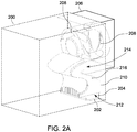
- FIG. 2A illustrates a perspective view of a portion 200 of a computer system with a remote intake 210, according to an embodiment of the present disclosure.
- the portion 200 is disclosed as a "portion," the portion 200 represents the computer system as a whole (e.g., computer system 200) rather than only a portion therein.
- the portion 200 includes an element 202, a heat sink 204, and a fan module 206 with fans 208, similar to the features discussed above with respect to FIGS. 1A and 1B .
- the portion 200 includes the remote intake 210.
- the remote intake 210 is configured to increase airflow at low airflow regions of the portion 200.
- the portion 200 may include a similar low airflow region as the low airflow region 105 within the portion 100 illustrated in FIG. 1B .
- the similarity of the low airflow regions is based on a similar arrangement of the fan module 206, the element 202, and the heat sink 204.
- the remote intake 210 therefore, is configured and arranged within the portion 200 to collect air surrounding the element 202 and the heat sink 204, and discharge the air into the fan module 206.
- the remote intake 210 can increase the airflow surrounding the element 202 and the heat sink 204.
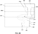
- the remote intake 210 has a remote inlet 212 configured to intake air from outside of the intake path 207 of the fan module 206.
- the intake path 207 of the fan module 206 generally extends-out parallel to the axis 208a of the fans 208.
- the intake path 207 is generally about the diameter of the fans 208 at the fan module 206, but can increase gradually away from the fan module 206.
- the element 202 and the heat sink 204 are directly below the fan module 206, the element 202 and the heat sink 204 are outside of the intake path 207.
- the remote inlet 212 can intake air surrounding the element 202 and the heat sink 204 to increase the airflow around the element 202. In turn, this increases heat dissipation, as discussed further below.
- the remote intake 210 further includes a remote outlet 214 configured to discharge the air from the remote inlet 212.
- the remote outlet 214 can be configured to discharge the air anywhere along the intake path 207 of the fan module 206.
- the remote outlet 214 can abut the leading edge 206a of the fan module 206.
- the remote outlet 214 discharges the air from the remote inlet 212 directly into the fans 208 of the fan module 206.
- the remote outlet 214 can be positioned within the intake path 207 and against the fan module 206 so that air discharged from the remote outlet 214 goes into the fans 208.
- the remote intake 210 further includes a remote conduit 216.
- the remote conduit 216 is configured to transport the air from the remote inlet 212 to the remote outlet 214.
- the remote conduit 216 can be any shape that connects the remote inlet 212 to the remote outlet 214.
- the remote conduit 216 has a curved geometry-rather than sharp corners-to assist in transporting the air from the remote inlet 212 to the remote outlet 214 with a more laminar flow.
- the remote conduit 216 can have an S-shape.
- the shape and the size of the remote conduit 216 can vary depending on the locations of the remote inlet 212 and the remote outlet 214.
- the remote outlet 214 can abut against the leading edge 206a of the fan module 206. The closer the remote outlet 214 is to the leading edge 206a of the fan module 206, the greater the negative air pressure that is created at the remote inlet 212, which further increases the airflow across the element 202 and the heat sink 204.
- the remote inlet 212 is configured to at least partially cover the heat sink 204 above the element 202. By at least partially covering the heat sink 204, the remote inlet 212 can increase the airflow over the heat sink 204 and around the element 202. This can increase the cooling of the element 202 and the heat sink 204 by the fan module 206.
- the remote inlet 212 can have a flat profile.
- the remote inlet 212 can have various profiles, shapes, or sizes to match the geometry of the element 102 that it is configured to cool, to match the geometry of the heat sink 204, or to match the geometry of the portion 100 of the computer which it is in.
- the size of the remote outlet 214 compared to the diameter of the fans 208 can be based on the cooling amount required for the element 202, the cooling efficiency of the heat sink 204, or both.
- the area that the remote inlet 212 is supposed to cover can also affect the size and shape of the remote outlet 214. The larger the area, the larger the remote outlet 214 compared to the size of the fans 208.
- FIG. 3A illustrates a perspective view of the remote intake 210, according to an embodiment of the present disclosure.
- FIG. 3B illustrates a sliced perspective view of the remote intake 210, according to an embodiment of the present disclosure.
- the remote inlet 212 can include a front side opening 212a.
- the front side opening 212a is configured to allow air to pass into the remote inlet 212 parallel to the direction of the intake path 207 of the fan module 206 ( FIG. 2B ).
- the front side opening 212a of the remote inlet 212 can increase airflow over the element 202 ( FIG. 2B ) as compared to, for example, a remote inlet with a flat profile.
- the remote inlet 212 can further include a back side opening 212b.
- the back side opening 212b can further increase airflow around the element 202 as compared to, for example, a remote inlet with a flat profile.
- the back side opening 212b is configured to allow the remote inlet 212 to be positioned around the element 202 and the heat sink 204 in a corner of the portion 200 of the computer system.
- the shape or profile of the remote inlet 212 with the front side opening 212a and the back side opening 212b can be, in part, to increase the airflow around the element 202 and the heat sink 204 ( FIG. 2B ).
- the shape or profile can also allow the remote inlet 212 to be positioned as needed within the portion 200 ( FIG. 2A ) of the computer system.
- the remote conduit 216 of the remote intake 210 can include a projection 216a.
- the projection 216a can provide structural rigidity for the remote intake 210.
- the projection 216a can aid in guiding air through the remote intake 210 to increase the airflow through the remote intake 210.
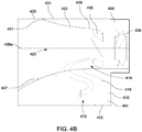
- FIG. 4A illustrates a perspective view of a portion 400 of a computer system with the intake system 420, according to an embodiment of the present disclosure.
- FIG. 4B illustrates a side view of the portion 400 of FIG. 4A , according to an embodiment of the present disclosure.
- FIG. 5A illustrates a perspective view of the intake system 420, according to an embodiment of the present disclosure.
- FIG. 5B illustrates a sliced perspective view of the intake system 420, according to an embodiment of the present disclosure.
- the portion 400 includes similar components as the portion 200 described above, including the element 402 to be cooled; the heat sink 404 above the element 402; and the fan module 406 with the fans 408 and associated axis 408a of the fans 408.
- the intake system 420 includes a remote intake 410 that is similar to the remote intake 210 described above ( FIGS. 2A-3B ). Accordingly, similarly numbered elements of the portion 400 and the remote intake 410 are as described above with respect to the components of the portion 200 and the remote intake 210, such as the remote inlet 412 with the front side opening 412a and the back side opening 412b.
- the intake system 420 further includes a cowling 422.
- the cowling 422 provides for more directed airflow through the portion 400 according to the intake path 407.
- the cowling 422 is positioned against the fan module 406 and within the intake path 407 ( FIG. 4B ) of the fan module 406.
- the cowling 422 is configured to direct air into the fan module 406.
- the cowling 422 can have various shapes. In one or more embodiments, the cowling 422 can be in the general shape of a bell. The general shape of a bell assists in expanding the intake path 407, as illustrated by the diverging lines representing the intake path 407 upwind from the fan module 406, and guiding the air into the fan module 406.
- the cowling 422 has a cowling inlet 424 that is configured to intake air.
- the cowling 422 further has a cowling outlet 426 that is configured to discharge air into the fans 408 of the fan module 406.
- the diameter of the cowling outlet 426 can vary, as further discussed below. In some embodiments, the diameter of the cowling outlet 426 can be about the same diameter as the diameter of the fans 408.
- a portion 416a of the remote conduit 416 can extend into the cowling 422 such that a volume of the cowling 422 is reduced by the portion 416a of the remote conduit 416.
- the diameter of the cowling 422 can match the diameter of the fans 408.
- both the cowling outlet 426 and the remote outlet 414 can be positioned to be within the intake path 407 of the fan module 406, as illustrated in FIG. 4B .
- the remote outlet 414 can be below the cowling 422 such that the remote conduit 416 does not extend into the cowling 422.
- the diameter of the cowling outlet 426 is smaller than the diameter of the fans 408 to provide room for the remote outlet 414 below the cowling outlet 426 to discharge air into the fans 408.
- the size of the remote outlet 414 compared to the cowling outlet 426 can be based on the cooling amount required for the element 402, the cooling efficiency of the heat sink 404, or both.
- the area that the remote inlet 412 is supposed to cover can also affect the size and shape of the remote outlet 414. The larger the area, the larger the remote outlet 414 compared to the size of the cowling outlet 426.
- the cowling outlet 426 can be flush with the remote outlet 414, as illustrated in FIGS. 4B and 5B . Such an arrangement allows the cowling outlet 426 and the remote outlet 414 to be against the fan module 406. However, in one or more embodiments, the cowling outlet 426 can be upwind or downwind relative to the remote outlet 414.
- FIG. 6A illustrates a perspective view of the intake system 620, according to an embodiment of the present disclosure.
- FIG. 6B illustrates a sliced perspective view of the intake system 620, according to an embodiment of the present disclosure.
- the intake system 620 is similar to the intake system 420 ( FIG. 5B ). Accordingly, similarly numbered elements of the intake system 620 are as described above with respect to the elements of the intake system 420. However, the remote outlet 614 of the remote intake 610 is configured to discharge air into the cowling 422 ( FIG. 5B ), rather than into a fan module.
- the remote outlet 614 can be an aperture within the cowling 622.
- the remote conduit 616 can extend up to, but stop at, the cowling 622. Air from the remote inlet 612 passes through the remote conduit 616 and is discharged from the remote outlet 614 into the cowling 622. From there, the air is mixed with air from the cowling 622 and is discharged into a fan module.
- the diameter of the cowling outlet 626 of the intake system 620 can be the same diameter as fans (e.g., fans 408 of FIG. 4A ) within a fan module (e.g., 406 of FIG. 4A ) against which the intake system 620 abuts.
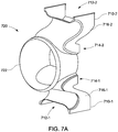
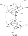
- FIG. 7A illustrates a perspective view of the intake system 720, according to an embodiment of the present disclosure.
- FIG. 7B illustrates a sliced perspective view of the intake system 720, according to an embodiment of the present disclosure.
- the intake system 720 is similar to the intake system 420 ( FIG. 5B ). Accordingly, similarly numbered elements of the intake system 720 are as described above with respect to the elements of the intake system 420.
- the intake system 720 includes two of various elements discussed above, such as two remote intakes 710-1 and 710-2 with the corresponding remote inlets 712-1 and 712-2, remote outlets 714-1 and 714-2, and remote conduits 716-1 and 716-2.
- the two remote intakes 710-1 and 710-2 can be positioned so as to increase the airflow around two separate elements within a computer system.
- the remote intakes 710-1 and 710-2 can be positioned on opposite sides of the cowling 722. This arrangement allows the remote intakes 710-1 and 710-2 to surround two elements within a computer system on opposite sides of the cowling 722.
- the dimensions and shapes of the two remote intakes 710-1 and 710-2 can be the same, such as what is illustrated in FIGS. 7A and 7B .
- the dimensions, shapes, or both of the remote intakes 710-1 and 710-2 can be different. The differences can be as needed to reach different elements or areas within a computer system.
- the remote intakes 710-1 and 710-2 are illustrated as being above and below the cowling 722, in one or more embodiments, the remote intakes 710-1 and 710-2 can be positioned according to any arrangement relative to the cowling 722. Further, although only two remote intakes 710-1 and 710-2 are shown, there can be more than two remote intakes 710 connected to the cowling 722 and arranged according to any arrangement to cool various elements within a computer system. For example, there can be three, four, five, or more remote intakes 710 around the cowling 722, to the extent that space for the remote intakes 710 is available.
- one or both of the remote intakes 710-1 and 710-2 can be configured according to the remote intake 610 ( FIG. 6B ). As such, one or both of the remote conduits 716-1 and 716-2 does not extend into the cowling 722. Instead, one or both of the remote outlets 714-1 and 714-2 can be configured as apertures within the cowling 722, such as the remote outlet 614 of the intake system 620 ( FIG. 6B ).
- FIG. 8 illustrates a pressure field plot of a portion 800 including an intake system 820, according to an embodiment of the present disclosure.
- the portion 800 and intake system 820 are similar to the portion 400 and the intake system 420 of FIGS. 4A and 4B . Accordingly, similarly numbered elements of the portion 800 and the intake system 820 are as described above with respect to the elements of the intake system 420.
- the portion 800 includes the element 802, the heat sink 804, and the fan module 806 with the fans 808.
- the portion 800 further includes a bracket 809.
- the bracket 809 can be for structural rigidity of the chassis of the computer system at the portion 800.
- the bracket 809 can be for attaching components to the computer system within the portion 800. Regardless of its purpose, the bracket 809 may further reduce the amount of airflow that the element 802 and the heat sink 804 experience.
- the intake system 820 includes the remote intake 810 connected to the cowling 822.
- the remote inlet 812 is above and partially surrounds the heat sink 804.
- the remote conduit 816 extends up from the remote inlet 812 to the remote outlet 814, which abuts the fan module 806 along with the cowling outlet 826 of the cowling 822.
- the air velocity over the heat sink 804 and the element 802 is about the same as the air velocity through the cowling 822. Accordingly, the combination of the cowling 822 and the remote intake 810 of the intake system 820 increases the airflow over the element 802 and the heat sink 804. The increased airflow increases the dissipation of heat generated by the element 802. The increased dissipation of heat allows for the element 802 to run cooler, which can increase performance of the element 802.
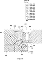
- FIG. 9 illustrates a pressure field plot of the intake system 820 of FIG. 8 , according to an embodiment of the present disclosure. Because of the remote intake 810, the fans 808 are able to create low pressure around the heat sink 804 and the element 802. The low pressure causes air to be sucked from around the element 802 and into the fans 808 of the fan module.
- the presence of the intake system of the present disclosure within a computer system allows for greater cooling of a chipset within a low airflow region.
- a comparison was done of the temperatures of a chipset both with and without the intake system of the present disclosure.
- the temperature of the chipset was measured to be about 47.7 °C at ambient conditions of 25 °C and a fan airflow rate of 50 cubic feet per minute (cfm).
- the temperature of the chipset was measured to be about 42.4 °C. Accordingly, the presence of the intake system increased the cooling, which amounted to a 23.3% increase in thermal performance.
Landscapes
- Engineering & Computer Science (AREA)
- Physics & Mathematics (AREA)
- Theoretical Computer Science (AREA)
- General Engineering & Computer Science (AREA)
- Microelectronics & Electronic Packaging (AREA)
- Thermal Sciences (AREA)
- Human Computer Interaction (AREA)
- General Physics & Mathematics (AREA)
- Mechanical Engineering (AREA)
- Fluid Mechanics (AREA)
- Cooling Or The Like Of Electrical Apparatus (AREA)
Abstract
Description
- The present invention relates to cooling computer systems and more specifically, to a remote intake port for cooling low airflow regions within computer systems.
- Cooling is important for maintaining optimal performance of components within computer systems. One or more fans within the computer systems direct air through the chassis to cool the components. However, low airflow regions exist within the chassis. These regions exist for various reasons, such as components blocking the airflow or the geometry of the chassis. Further, the desire to maximize the space within computer systems further causes low airflow regions. Accordingly, components within the low airflow regions may overheat. Overheating may cause a decrease in performance or may damage or destroy the components in severe situations.
-
FIG. 1A illustrates a perspective view of aportion 100 of a chassis of a computer system housing anelement 102 that needs to be cooled. Theelement 102 can be, for example, a processor, a chipset, or any other element within a computer system that generates heat. Theelement 102 is attached to aheat sink 104 that assists in dissipating the generated heat. Theportion 100 of the chassis includes afan module 106 that includesfans 108. Thefans 108 generate airflow through theportion 100. The airflow assists in dissipating heat generated by elements within the computer system, such as theelement 102. -
FIG. 1B illustrates a side view of theportion 100 ofFIG. 1A and includesarrows portion 100. Airflow represented by thearrows 110a is directed towards thefan module 106. This airflow is generally within theintake path 107 of thefan module 106. Theintake path 107 extends-out parallel to theaxis 108a of thefans 108, within thefan module 106. Theintake path 107 accounts for a majority of the air that passes through thefan module 106. Airflow represented by thearrows 110b is outside of theintake path 107. This air can still pass through thefan module 106 but is outside of theintake path 107. - The arrangement of the
fan module 106 within theportion 100 generates alow airflow region 105. Thearrows low airflow region 105 by not passing through thelow airflow region 105. Thislow airflow region 105 has low airflow primarily because theregion 105 is outside theintake path 107 offan module 106. In particular, thelow airflow region 105 is below thefan module 106 and downstream from the leadingedge 106a of thefan module 106. The result is that heat may build up in theelement 102 because theelement 102 and theheat sink 104 are not experiencing enough airflow to dissipate generated heat. The failure to dissipate the heat can cause issues in theelement 102, such as preventing certain elements from being placed at the location of theelement 102. - In some situations, the airflow within the
low airflow region 105 may be reduced even further because of other components within theportion 100 that block the airflow. Such other components can be, for example, a structural component that blocks theheat sink 104 andelement 102. - Accordingly, there is a need for a way to improve airflow in low airflow regions in computer systems.
- According to one embodiment, an intake system for a fan module within a computer system is disclosed. The intake system includes a cowling positioned within an intake path of the fan module. The cowling is configured to direct air into the fan module. The intake system further includes a remote intake having a remote inlet, a remote outlet, and a remote conduit. The remote inlet is configured to intake air from around an element that is within the computer system and outside of the intake path of the fan module. The remote outlet is configured to discharge the air from the remote inlet into the intake path of the fan module. The remote conduit is configured to transport the air from the remote inlet to the remote outlet.
- According to aspects of the embodiment, the cowling can have a cowling inlet configured to intake air along the intake path, and a cowling outlet configured to discharge air into a fan of the fan module. The cowling inlet can have a bell-shape. The remote outlet and the cowling outlet can discharge air parallel to the intake path. The area of the remote outlet can be less than, more than, or the same area as the cowling outlet. The remote conduit can at least partially define a surface of the cowling. The remote outlet can be configured to discharge air into the cowling by the remote outlet being an aperture in the cowling. The remote outlet can be configured to discharge air into a fan of the fan module. The intake system can have two or more of the remote intake. The two or more of the remote intake can be a pair of the remote intake that are configured to intake air from around elements on opposite sides of the cowling. The remote outlet can be configured to discharge air parallel to the direction of the intake path. The remote inlet can be configured to at least partially cover the element. The remote conduit can have a curved geometry; such being S-shaped. The cowling and the remote outlet can be flush against the fan module.
- According to another embodiment, a remote intake for a fan module within a computer system is disclosed. The remote intake includes a remote inlet configured to intake air from around an element that is within the computer system and outside of an intake path of the fan module. The remote intake further includes a remote outlet configured to discharge the air from the remote inlet into the intake path of the fan module. The remote intake further includes a remote conduit configured to transport the air from the remote inlet to the remote outlet.
- According to aspects of the embodiment, the remote outlet can be configured to discharge the air into a fan of the fan module. The remote outlet can be configured to discharge the air parallel to the intake path. The remote inlet can be configured to at least partially cover the element. The remote conduit can have a curved geometry; such being S-shaped.
- The above summary is not intended to represent each embodiment or every aspect of the present disclosure. Rather, the foregoing summary merely provides an example of some of the novel aspects and features set forth herein. The above features and advantages, and other features and advantages of the present disclosure, will be readily apparent from the following detailed description of representative embodiments and modes for carrying out the present invention, when taken in connection with the accompanying drawings and the appended claims.
- The disclosure, and its advantages and drawings, will be better understood from the following description of exemplary embodiments together with reference to the accompanying drawings. These drawings depict only exemplary embodiments and are, therefore, not to be considered as limitations on the scope of the various embodiments or claims.
-
FIG. 1A illustrates a perspective view of a portion of a computer system. -
FIG. 1B illustrates a side view of the portion inFIG. 1A . -
FIG. 2A illustrates a perspective view of a portion of a computer system with a remote intake, according to an embodiment of the present disclosure. -
FIG. 2B illustrates a side view of the portion ofFIG. 2A , according to an embodiment of the present disclosure. -
FIG. 3A illustrates a perspective view of a remote intake, according to an embodiment of the present disclosure. -
FIG. 3B illustrates a sliced-perspective view of the remote intake ofFIG. 3A , according to an embodiment of the present disclosure. -
FIG. 4A illustrates a perspective view of a portion of a computer system with an intake system, according to an embodiment of the present disclosure. -
FIG. 4B illustrates a side view of the portion ofFIG. 4A , according to an embodiment of the present disclosure. -
FIG. 5A illustrates a perspective view of an intake system, according to an embodiment of the present disclosure. -
FIG. 5B illustrates a sliced-perspective view of the intake system ofFIG. 5A , according to an embodiment of the present disclosure. -
FIG. 6A illustrates a perspective view of another intake system, according to an embodiment of the present disclosure. -
FIG. 6B illustrates a sliced-perspective perspective view of the intake system ofFIG. 6A , according to an embodiment of the present disclosure. -
FIG. 7A illustrates a perspective view of another intake system, according to an embodiment of the present disclosure. -
FIG. 7B illustrates a sliced-perspective perspective view of the intake system ofFIG. 7A , according to an embodiment of the present disclosure. -
FIG. 8 illustrates a streamline plot of an intake system, according to an embodiment of the present disclosure. -
FIG. 9 illustrates a pressure field plot of the intake system ofFIG. 8 , according to an embodiment of the present disclosure. - The various embodiments are described with reference to the attached figures, where like reference numerals are used throughout the figures to designate similar or equivalent elements. The figures are not drawn to scale, and they are provided merely to illustrate the instant invention. It should be understood that numerous specific details, relationships, and methods are set forth to provide a full understanding. One having ordinary skill in the relevant art, however, will readily recognize that the various embodiments can be practiced without one or more of the specific details, or with other methods. In other instances, well-known structures or operations are not shown in detail to avoid obscuring certain aspects of the various embodiments. The various embodiments are not limited by the illustrated ordering of acts or events, as some acts may occur in different orders and/or concurrently with other acts or events. Furthermore, not all illustrated acts or events are required to implement a methodology in accordance with the present invention.
- Elements and limitations that are disclosed, for example, in the Abstract, Summary, and Detailed Description sections, but not explicitly set forth in the claims, should not be incorporated into the claims, singly, or collectively, by implication, inference, or otherwise. For purposes of the present detailed description, unless specifically disclaimed, the singular includes the plural and vice versa. The word "including" means "including without limitation." Moreover, words of approximation, such as "about," "almost," "substantially," "approximately," and the like, can be used herein to mean "at," "near," or "nearly at," or "within 3-5% of," or "within acceptable manufacturing tolerances," or any logical combination thereof, for example.
- With regards to the present disclosure, the terms "computing device" or "computing system" or "computer system" refer to any electronically-powered or battery-powered equipment that has hardware, software, and/or firmware components, where the software and/or firmware components can be configured for operating features on the device. The term "operating environment" can refer to any operating system or environment that functions to allow software to run on a computer system.
- The present disclosure describes a remote intake that can be used within a computer system to increase the airflow within low airflow regions of the computer system. The remote intake includes an inlet and an outlet. The inlet is positioned within the low airflow region of the computer system. The outlet is positioned at a fan module of the computer system. The remote intake includes a conduit that transports air between the inlet and the outlet. As a result of the remote intake, airflow can be increased at the low airflow regions. Thus, computer elements at the low airflow regions can be sufficiently cooled. Further, with the remote intake, computer elements may be positioned in computer systems where previously unable because of low airflow.
- The present disclosure also describes intake systems. The systems include a cowling that is positioned at a fan module within the computer system. One or more remote intakes, as described above, are combined with the cowling to increase the airflow within low airflow regions of the computer system. The remote intakes can be the same size and shape, or different sizes and shapes, depending on the arrangement of the low airflow regions within the computer system. Use of the remote intakes or intake systems within a computer system can increase the available space to place computer elements by increasing the space within the computer systems that can be cooled.
-
FIG. 2A illustrates a perspective view of aportion 200 of a computer system with aremote intake 210, according to an embodiment of the present disclosure. Although theportion 200 is disclosed as a "portion," theportion 200 represents the computer system as a whole (e.g., computer system 200) rather than only a portion therein. Theportion 200 includes anelement 202, aheat sink 204, and afan module 206 withfans 208, similar to the features discussed above with respect toFIGS. 1A and1B . In addition, theportion 200 includes theremote intake 210. - The
remote intake 210 is configured to increase airflow at low airflow regions of theportion 200. For example, theportion 200 may include a similar low airflow region as thelow airflow region 105 within theportion 100 illustrated inFIG. 1B . The similarity of the low airflow regions is based on a similar arrangement of thefan module 206, theelement 202, and theheat sink 204. Theremote intake 210, therefore, is configured and arranged within theportion 200 to collect air surrounding theelement 202 and theheat sink 204, and discharge the air into thefan module 206. As a result, theremote intake 210 can increase the airflow surrounding theelement 202 and theheat sink 204. - The
remote intake 210 has aremote inlet 212 configured to intake air from outside of theintake path 207 of thefan module 206. Referring toFIG. 2B , theintake path 207 of thefan module 206 generally extends-out parallel to theaxis 208a of thefans 208. Theintake path 207 is generally about the diameter of thefans 208 at thefan module 206, but can increase gradually away from thefan module 206. Thus, because theelement 202 and theheat sink 204 are directly below thefan module 206, theelement 202 and theheat sink 204 are outside of theintake path 207. With theremote inlet 212 at theelement 202 and theheat sink 204, theremote inlet 212 can intake air surrounding theelement 202 and theheat sink 204 to increase the airflow around theelement 202. In turn, this increases heat dissipation, as discussed further below. - The
remote intake 210 further includes aremote outlet 214 configured to discharge the air from theremote inlet 212. In one or more embodiments, theremote outlet 214 can be configured to discharge the air anywhere along theintake path 207 of thefan module 206. In one or more embodiments, and as illustrated inFIG. 2B , theremote outlet 214 can abut theleading edge 206a of thefan module 206. Theremote outlet 214 discharges the air from theremote inlet 212 directly into thefans 208 of thefan module 206. Specifically, theremote outlet 214 can be positioned within theintake path 207 and against thefan module 206 so that air discharged from theremote outlet 214 goes into thefans 208. - The
remote intake 210 further includes aremote conduit 216. Theremote conduit 216 is configured to transport the air from theremote inlet 212 to theremote outlet 214. Theremote conduit 216 can be any shape that connects theremote inlet 212 to theremote outlet 214. Preferably, theremote conduit 216 has a curved geometry-rather than sharp corners-to assist in transporting the air from theremote inlet 212 to theremote outlet 214 with a more laminar flow. In one or more embodiments, and as illustrated inFIGS. 2A and2B , theremote conduit 216 can have an S-shape. However, the shape and the size of theremote conduit 216 can vary depending on the locations of theremote inlet 212 and theremote outlet 214. - As discussed above, the
remote outlet 214 can abut against the leadingedge 206a of thefan module 206. The closer theremote outlet 214 is to theleading edge 206a of thefan module 206, the greater the negative air pressure that is created at theremote inlet 212, which further increases the airflow across theelement 202 and theheat sink 204. - As shown in
FIG. 2B , in one or more embodiments, theremote inlet 212 is configured to at least partially cover theheat sink 204 above theelement 202. By at least partially covering theheat sink 204, theremote inlet 212 can increase the airflow over theheat sink 204 and around theelement 202. This can increase the cooling of theelement 202 and theheat sink 204 by thefan module 206. - In one or more embodiments, the
remote inlet 212 can have a flat profile. Alternatively, theremote inlet 212 can have various profiles, shapes, or sizes to match the geometry of theelement 102 that it is configured to cool, to match the geometry of theheat sink 204, or to match the geometry of theportion 100 of the computer which it is in. - In one or more embodiments, the size of the
remote outlet 214 compared to the diameter of thefans 208 can be based on the cooling amount required for theelement 202, the cooling efficiency of theheat sink 204, or both. The larger the cooling requirement or the smaller the efficiency, than the larger theremote outlet 214 that is needed to cool theelement 202. The area that theremote inlet 212 is supposed to cover can also affect the size and shape of theremote outlet 214. The larger the area, the larger theremote outlet 214 compared to the size of thefans 208. -
FIG. 3A illustrates a perspective view of theremote intake 210, according to an embodiment of the present disclosure.FIG. 3B illustrates a sliced perspective view of theremote intake 210, according to an embodiment of the present disclosure. In one or more embodiments, theremote inlet 212 can include afront side opening 212a. Thefront side opening 212a is configured to allow air to pass into theremote inlet 212 parallel to the direction of theintake path 207 of the fan module 206 (FIG. 2B ). Thefront side opening 212a of theremote inlet 212 can increase airflow over the element 202 (FIG. 2B ) as compared to, for example, a remote inlet with a flat profile. - In one or more embodiments, the
remote inlet 212 can further include aback side opening 212b. Theback side opening 212b can further increase airflow around theelement 202 as compared to, for example, a remote inlet with a flat profile. Theback side opening 212b is configured to allow theremote inlet 212 to be positioned around theelement 202 and theheat sink 204 in a corner of theportion 200 of the computer system. - The shape or profile of the
remote inlet 212 with thefront side opening 212a and theback side opening 212b can be, in part, to increase the airflow around theelement 202 and the heat sink 204 (FIG. 2B ). The shape or profile can also allow theremote inlet 212 to be positioned as needed within the portion 200 (FIG. 2A ) of the computer system. - As illustrated in
FIG. 3B , in one or more embodiments, theremote conduit 216 of theremote intake 210 can include aprojection 216a. Theprojection 216a can provide structural rigidity for theremote intake 210. Alternatively, or in addition, theprojection 216a can aid in guiding air through theremote intake 210 to increase the airflow through theremote intake 210. - An
intake system 420 according to the present disclosure will now be described in reference toFIGS. 4A-5B .FIG. 4A illustrates a perspective view of aportion 400 of a computer system with theintake system 420, according to an embodiment of the present disclosure.FIG. 4B illustrates a side view of theportion 400 ofFIG. 4A , according to an embodiment of the present disclosure.FIG. 5A illustrates a perspective view of theintake system 420, according to an embodiment of the present disclosure.FIG. 5B illustrates a sliced perspective view of theintake system 420, according to an embodiment of the present disclosure. - The
portion 400 includes similar components as theportion 200 described above, including theelement 402 to be cooled; theheat sink 404 above theelement 402; and thefan module 406 with thefans 408 and associatedaxis 408a of thefans 408. Theintake system 420 includes aremote intake 410 that is similar to theremote intake 210 described above (FIGS. 2A-3B ). Accordingly, similarly numbered elements of theportion 400 and theremote intake 410 are as described above with respect to the components of theportion 200 and theremote intake 210, such as theremote inlet 412 with thefront side opening 412a and theback side opening 412b. - The
intake system 420 further includes acowling 422. Thecowling 422 provides for more directed airflow through theportion 400 according to theintake path 407. Thecowling 422 is positioned against thefan module 406 and within the intake path 407 (FIG. 4B ) of thefan module 406. Thecowling 422 is configured to direct air into thefan module 406. Thecowling 422 can have various shapes. In one or more embodiments, thecowling 422 can be in the general shape of a bell. The general shape of a bell assists in expanding theintake path 407, as illustrated by the diverging lines representing theintake path 407 upwind from thefan module 406, and guiding the air into thefan module 406. - The
cowling 422 has acowling inlet 424 that is configured to intake air. Thecowling 422 further has acowling outlet 426 that is configured to discharge air into thefans 408 of thefan module 406. In one or more embodiments, the diameter of thecowling outlet 426 can vary, as further discussed below. In some embodiments, the diameter of thecowling outlet 426 can be about the same diameter as the diameter of thefans 408. - Referring to
FIG. 5A , in one or more embodiments, aportion 416a of theremote conduit 416 can extend into thecowling 422 such that a volume of thecowling 422 is reduced by theportion 416a of theremote conduit 416. With theportion 416a of theremote conduit 416 extending into thecowling 422, the diameter of thecowling 422 can match the diameter of thefans 408. However, both thecowling outlet 426 and theremote outlet 414 can be positioned to be within theintake path 407 of thefan module 406, as illustrated inFIG. 4B . In one or more alternative embodiments, theremote outlet 414 can be below thecowling 422 such that theremote conduit 416 does not extend into thecowling 422. In such embodiments, the diameter of thecowling outlet 426 is smaller than the diameter of thefans 408 to provide room for theremote outlet 414 below thecowling outlet 426 to discharge air into thefans 408. - In one or more embodiments, the size of the
remote outlet 414 compared to thecowling outlet 426 can be based on the cooling amount required for theelement 402, the cooling efficiency of theheat sink 404, or both. The larger the cooling requirement or the smaller the efficiency, than the larger theremote outlet 414 that is needed to cool theelement 402. The area that theremote inlet 412 is supposed to cover can also affect the size and shape of theremote outlet 414. The larger the area, the larger theremote outlet 414 compared to the size of thecowling outlet 426. - In one or more embodiments, the
cowling outlet 426 can be flush with theremote outlet 414, as illustrated inFIGS. 4B and5B . Such an arrangement allows thecowling outlet 426 and theremote outlet 414 to be against thefan module 406. However, in one or more embodiments, thecowling outlet 426 can be upwind or downwind relative to theremote outlet 414. - An
alternative intake system 620 of the present disclosure is described with respect toFIGS. 6A and6B .FIG. 6A illustrates a perspective view of theintake system 620, according to an embodiment of the present disclosure.FIG. 6B illustrates a sliced perspective view of theintake system 620, according to an embodiment of the present disclosure. - The
intake system 620 is similar to the intake system 420 (FIG. 5B ). Accordingly, similarly numbered elements of theintake system 620 are as described above with respect to the elements of theintake system 420. However, theremote outlet 614 of theremote intake 610 is configured to discharge air into the cowling 422 (FIG. 5B ), rather than into a fan module. - As illustrated in
FIGS. 6A and6B , theremote outlet 614 can be an aperture within thecowling 622. Theremote conduit 616 can extend up to, but stop at, thecowling 622. Air from theremote inlet 612 passes through theremote conduit 616 and is discharged from theremote outlet 614 into thecowling 622. From there, the air is mixed with air from thecowling 622 and is discharged into a fan module. The diameter of thecowling outlet 626 of theintake system 620 can be the same diameter as fans (e.g.,fans 408 ofFIG. 4A ) within a fan module (e.g., 406 ofFIG. 4A ) against which theintake system 620 abuts. - An
alternative intake system 720 of the present disclosure is described with respect toFIGS. 7A and7B .FIG. 7A illustrates a perspective view of theintake system 720, according to an embodiment of the present disclosure.FIG. 7B illustrates a sliced perspective view of theintake system 720, according to an embodiment of the present disclosure. Theintake system 720 is similar to the intake system 420 (FIG. 5B ). Accordingly, similarly numbered elements of theintake system 720 are as described above with respect to the elements of theintake system 420. However, theintake system 720 includes two of various elements discussed above, such as two remote intakes 710-1 and 710-2 with the corresponding remote inlets 712-1 and 712-2, remote outlets 714-1 and 714-2, and remote conduits 716-1 and 716-2. The two remote intakes 710-1 and 710-2 can be positioned so as to increase the airflow around two separate elements within a computer system. For example, and as illustrated inFIGS. 7A and7B , the remote intakes 710-1 and 710-2 can be positioned on opposite sides of thecowling 722. This arrangement allows the remote intakes 710-1 and 710-2 to surround two elements within a computer system on opposite sides of thecowling 722. - The dimensions and shapes of the two remote intakes 710-1 and 710-2 can be the same, such as what is illustrated in
FIGS. 7A and7B . Alternatively, the dimensions, shapes, or both of the remote intakes 710-1 and 710-2 can be different. The differences can be as needed to reach different elements or areas within a computer system. - Although the remote intakes 710-1 and 710-2 are illustrated as being above and below the
cowling 722, in one or more embodiments, the remote intakes 710-1 and 710-2 can be positioned according to any arrangement relative to thecowling 722. Further, although only two remote intakes 710-1 and 710-2 are shown, there can be more than two remote intakes 710 connected to thecowling 722 and arranged according to any arrangement to cool various elements within a computer system. For example, there can be three, four, five, or more remote intakes 710 around thecowling 722, to the extent that space for the remote intakes 710 is available. - Although the remote conduits 716-1 and 716-2 are illustrated as extending into the
cowling 722, similar to the remote conduit 416 (FIG. 5B ), in one or more embodiments, one or both of the remote intakes 710-1 and 710-2 can be configured according to the remote intake 610 (FIG. 6B ). As such, one or both of the remote conduits 716-1 and 716-2 does not extend into thecowling 722. Instead, one or both of the remote outlets 714-1 and 714-2 can be configured as apertures within thecowling 722, such as theremote outlet 614 of the intake system 620 (FIG. 6B ). -
FIG. 8 illustrates a pressure field plot of aportion 800 including anintake system 820, according to an embodiment of the present disclosure. Theportion 800 andintake system 820 are similar to theportion 400 and theintake system 420 ofFIGS. 4A and4B . Accordingly, similarly numbered elements of theportion 800 and theintake system 820 are as described above with respect to the elements of theintake system 420. - The
portion 800 includes theelement 802, theheat sink 804, and thefan module 806 with thefans 808. Theportion 800 further includes abracket 809. Thebracket 809 can be for structural rigidity of the chassis of the computer system at theportion 800. Alternatively, thebracket 809 can be for attaching components to the computer system within theportion 800. Regardless of its purpose, thebracket 809 may further reduce the amount of airflow that theelement 802 and theheat sink 804 experience. - The
intake system 820 includes theremote intake 810 connected to thecowling 822. Theremote inlet 812 is above and partially surrounds theheat sink 804. Theremote conduit 816 extends up from theremote inlet 812 to theremote outlet 814, which abuts thefan module 806 along with thecowling outlet 826 of thecowling 822. - As shown by the air velocities and corresponding legend, the air velocity over the
heat sink 804 and theelement 802 is about the same as the air velocity through thecowling 822. Accordingly, the combination of thecowling 822 and theremote intake 810 of theintake system 820 increases the airflow over theelement 802 and theheat sink 804. The increased airflow increases the dissipation of heat generated by theelement 802. The increased dissipation of heat allows for theelement 802 to run cooler, which can increase performance of theelement 802. -
FIG. 9 illustrates a pressure field plot of theintake system 820 ofFIG. 8 , according to an embodiment of the present disclosure. Because of theremote intake 810, thefans 808 are able to create low pressure around theheat sink 804 and theelement 802. The low pressure causes air to be sucked from around theelement 802 and into thefans 808 of the fan module. - The presence of the intake system of the present disclosure within a computer system allows for greater cooling of a chipset within a low airflow region. A comparison was done of the temperatures of a chipset both with and without the intake system of the present disclosure. For a 5-Watt chipset as the element (e.g.,
element 802 ofFIG. 8 ) located under a fan module (e.g.,fan module 806 ofFIG. 8 ), the temperature of the chipset was measured to be about 47.7 °C at ambient conditions of 25 °C and a fan airflow rate of 50 cubic feet per minute (cfm). At the same conditions, but with the intake system of the present disclosure against the fan module and surrounding the chipset, the temperature of the chipset was measured to be about 42.4 °C. Accordingly, the presence of the intake system increased the cooling, which amounted to a 23.3% increase in thermal performance.
Claims (15)
- An intake system (420, 620, 720, 820) for a fan module (206, 406, 806) within a computer system, the intake system (420, 620, 720, 820) comprising:a cowling (422, 622, 722, 822) positioned in line with an intake path (207, 407) of the fan module (206, 406, 806), the cowling (422, 622, 722, 822) configured to direct air into the fan module (206, 406, 806); andat least one remote intake (210, 410, 610, 710-1,710-2, 810) having:a remote inlet (212, 412, 712-1, 712-2, 812)configured to intake air from around an element (202, 402, 802) that is within the computer system and outside of the intake path (207, 407) of the fan module (206, 406, 806);a remote outlet (214, 414, 614, 714-1, 714-2, 814) configured to discharge the air from the remote inlet (212, 412, 712-1, 712-2, 812) into the intake path (207, 407) of the fan module (206, 406, 806); anda remote conduit (216, 416, 616, 716-1, 716-2, 816) configured to transport the air from the remote inlet (212, 412, 712-1, 712-2, 812) to the remote outlet (214, 414, 614, 714-1, 714-2, 814).
- The intake system (420, 620, 720, 820) of claim 1, wherein the cowling (422, 622, 722, 822) includes a cowling inlet (424) configured to intake air along the intake path (207, 407), and a cowling outlet (426, 626, 826) configured to discharge air into a fan (208, 408, 808) of the fan module (206, 406, 806).
- The intake system (420, 620, 720, 820) of claim 2, wherein the remote outlet (214, 414, 614, 714-1, 714-2, 814) and the cowling outlet (426, 626, 826) are parallel to the intake path (207, 407).
- The intake system (420, 620, 720, 820) of claims 2 or 3, wherein the area of the remote outlet (212, 412, 712-1, 712-2, 812) is less than the area of the cowling outlet (426, 626, 826).
- The intake system (420, 620, 720, 820) of any of claims 1-4, wherein the remote outlet (214, 414, 614, 714-1, 714-2, 814) is configured to discharge air into the cowling (422, 622, 722, 822) or a fan (208, 408, 808) of the fan module.
- The intake system (420, 620, 720, 820) of claim 5, wherein the remote outlet (614, 714-1, 714-2, 814) is an aperture in the cowling (422, 622, 722, 822).
- The intake system (420, 620, 720, 820) of claim 1, wherein the at least one remote intake (210, 410, 610, 710-1,710-2, 810) comprises two or more remote intakes.
- The intake system (420, 620, 720, 820) of claim 7, wherein the two or more remote intake comprise a pair of the remote intakes (710-1,710-2) configured to intake air from around elements (202, 402, 802) on opposite sides of the cowling (422, 622, 722, 822).
- The intake system (420, 620, 720, 820) of any of claims 1-8, wherein the remote outlet (214, 414, 614, 714-1, 714-2, 814) is configured to discharge air parallel to the direction of the intake path (207, 407).
- The intake system (420, 620, 720, 820) of claim 1, wherein the cowling (422, 622, 722, 822) and the remote outlet (214, 414, 614, 714-1, 714-2, 814) are flush against the fan module (206, 406, 806).
- A remote intake (210, 410, 610, 710-1,710-2, 810) for a fan module (206, 406, 806) within a computer system, the remote intake comprising:a remote inlet (212, 412, 712-1, 712-2, 812) configured to intake air from around an element that is within the computer system and outside of an intake path (207, 407) of the fan module (206, 406, 806);a remote outlet (214, 414, 614, 714-1, 714-2, 814) configured to discharge the air from the remote inlet (212, 412, 712-1, 712-2, 812) into the intake path (207, 407) of the fan module (206, 406, 806); anda remote conduit (216, 416, 616, 716-1, 716-2, 816) configured to transport the air from the remote inlet (212, 412, 712-1, 712-2, 812) to the remote outlet (214, 414, 614, 714-1, 714-2, 814).
- The remote intake (210, 410, 610, 710-1,710-2, 810) of claim 11, wherein the remote outlet (214, 414, 614, 714-1, 714-2, 814) is configured to discharge the air into a fan (208, 408, 808) of the fan module (206, 406, 806).
- The remote intake (210, 410, 610, 710-1,710-2, 810) of claims 11 or 12, wherein the remote outlet (214, 414, 614, 714-1, 714-2, 814) is configured to discharge the air parallel to the direction of the intake path (207, 407).
- The remote intake (210, 410, 610, 710-1,710-2, 810) of any of claims11-13, wherein the remote inlet (212, 412, 712-1, 712-2, 812) is configured to at least partially cover the element (202, 402, 802).
- The remote intake (210, 410, 610, 710-1,710-2, 810) of any of claims 11-14, wherein the remote conduit (216, 416, 616, 716-1, 716-2, 816) is S-shaped.
Applications Claiming Priority (1)
| Application Number | Priority Date | Filing Date | Title |
|---|---|---|---|
| US16/392,012 US10782750B1 (en) | 2019-04-23 | 2019-04-23 | Remote intake for fan module |
Publications (2)
| Publication Number | Publication Date |
|---|---|
| EP3731062A1 true EP3731062A1 (en) | 2020-10-28 |
| EP3731062B1 EP3731062B1 (en) | 2022-05-04 |
Family
ID=67659219
Family Applications (1)
| Application Number | Title | Priority Date | Filing Date |
|---|---|---|---|
| EP19192211.1A Active EP3731062B1 (en) | 2019-04-23 | 2019-08-19 | Intake system for fan module |
Country Status (5)
| Country | Link |
|---|---|
| US (1) | US10782750B1 (en) |
| EP (1) | EP3731062B1 (en) |
| JP (1) | JP6887004B2 (en) |
| CN (1) | CN111831085A (en) |
| TW (1) | TWI704447B (en) |
Families Citing this family (1)
| Publication number | Priority date | Publication date | Assignee | Title |
|---|---|---|---|---|
| CN116266982B (en) * | 2021-12-16 | 2026-03-20 | 台达电子企业管理(上海)有限公司 | Power supply device |
Citations (2)
| Publication number | Priority date | Publication date | Assignee | Title |
|---|---|---|---|---|
| US5297005A (en) * | 1992-09-28 | 1994-03-22 | Energy Innovations, Inc. | Apparatus and method for cooling heat generating electronic components in a cabinet |
| US20110299240A1 (en) * | 2008-12-02 | 2011-12-08 | Hitachi, Ltd | Operation processor |
Family Cites Families (21)
| Publication number | Priority date | Publication date | Assignee | Title |
|---|---|---|---|---|
| DE3728484C2 (en) * | 1987-08-26 | 1996-09-05 | Schultz Gmbh Aurora | fan |
| US5597035A (en) * | 1995-08-18 | 1997-01-28 | Dell Usa, L.P. | For use with a heatsink a shroud having a varying cross-sectional area |
| US5987908A (en) * | 1997-09-25 | 1999-11-23 | Floratech Industries | Self-contained air conditioner with discharge-air filter |
| US6253834B1 (en) * | 1998-10-28 | 2001-07-03 | Hewlett-Packard Company | Apparatus to enhance cooling of electronic device |
| US6236565B1 (en) * | 2000-06-15 | 2001-05-22 | Mark G. Gordon | Chip stack with active cooling system |
| US6525936B2 (en) * | 2001-04-30 | 2003-02-25 | Hewlett-Packard Company | Air jet cooling arrangement for electronic systems |
| US6744630B2 (en) * | 2002-06-20 | 2004-06-01 | Dell Products L.P. | Variable length and directional cooling duct |
| US6930882B2 (en) * | 2003-04-07 | 2005-08-16 | Dell Products L.P. | Processor shroud adaptor for multiple CPU locations |
| US6970353B2 (en) * | 2003-05-29 | 2005-11-29 | Sun Microsystems, Inc. | Fan holder and components cooling duct assembly |
| US7256993B2 (en) * | 2004-04-05 | 2007-08-14 | Dell Products L.P. | Adjustable heat sink shroud |
| US7310228B2 (en) * | 2006-04-10 | 2007-12-18 | Super Micro Computer, Inc. | Air shroud for dissipating heat from an electronic component |
| JP5011016B2 (en) * | 2007-07-30 | 2012-08-29 | 株式会社日立産機システム | Power converter |
| US8432679B2 (en) * | 2010-06-15 | 2013-04-30 | Apple Inc. | Silicone barrier for drive window |
| US8679210B2 (en) * | 2012-01-17 | 2014-03-25 | Hamilton Sundstrand Corporation | Shrouded particle separator |
| CN104648674A (en) * | 2013-11-22 | 2015-05-27 | 中国航空工业集团公司西安飞机设计研究所 | Low-resistance fan-aided ejecting air feeding device |
| TWM505789U (en) | 2014-12-31 | 2015-07-21 | Celestica Int Inc | Wind guiding structure |
| US20160198593A1 (en) * | 2015-01-06 | 2016-07-07 | Dell Products, L.P. | Mixed/multi-mode cooling using air handling units (ahu) providing directed controlled cooling to a modular data center |
| CN205375359U (en) * | 2016-01-29 | 2016-07-06 | 苏州三星电子电脑有限公司 | Notebook radiator fan and notebook computer who constitutes thereof |
| CN108932039B (en) * | 2017-05-26 | 2021-08-13 | 鸿富锦精密工业(武汉)有限公司 | Air hood and cooling system |
| US20190024675A1 (en) * | 2017-07-20 | 2019-01-24 | Quanta Computer Inc. | Fan front intake for server fan module |
| US10555441B2 (en) | 2018-01-26 | 2020-02-04 | Super Micro Computer Inc. | Winds shroud and server using the same |
-
2019
- 2019-04-23 US US16/392,012 patent/US10782750B1/en active Active
- 2019-07-09 TW TW108124165A patent/TWI704447B/en active
- 2019-07-29 CN CN201910687307.6A patent/CN111831085A/en active Pending
- 2019-08-19 EP EP19192211.1A patent/EP3731062B1/en active Active
- 2019-09-27 JP JP2019176628A patent/JP6887004B2/en active Active
Patent Citations (2)
| Publication number | Priority date | Publication date | Assignee | Title |
|---|---|---|---|---|
| US5297005A (en) * | 1992-09-28 | 1994-03-22 | Energy Innovations, Inc. | Apparatus and method for cooling heat generating electronic components in a cabinet |
| US20110299240A1 (en) * | 2008-12-02 | 2011-12-08 | Hitachi, Ltd | Operation processor |
Also Published As
| Publication number | Publication date |
|---|---|
| EP3731062B1 (en) | 2022-05-04 |
| JP6887004B2 (en) | 2021-06-16 |
| JP2020181562A (en) | 2020-11-05 |
| TW202040312A (en) | 2020-11-01 |
| US10782750B1 (en) | 2020-09-22 |
| TWI704447B (en) | 2020-09-11 |
| CN111831085A (en) | 2020-10-27 |
Similar Documents
| Publication | Publication Date | Title |
|---|---|---|
| US7986521B2 (en) | Heat dissipation device and computer using same | |
| US7248472B2 (en) | Air distribution system | |
| US8514574B2 (en) | Heat dissipating apparatus | |
| US20120327589A1 (en) | Computer system with airflow guiding duct | |
| US20100074742A1 (en) | Centrifugal fan | |
| US20110090643A1 (en) | Computer system | |
| US11397453B2 (en) | Heat dissipation system | |
| US20190182989A1 (en) | Adapting frame for rack door | |
| US7898805B2 (en) | Central pressuring fan with bottom inlets for notebook cooling | |
| CN102236396A (en) | Server heat dissipation system | |
| US10927848B2 (en) | Fan module and electronic device | |
| US8120909B2 (en) | Computer system with airflow guiding duct | |
| US6785145B1 (en) | Cooling duct for computer | |
| US8941986B2 (en) | Computer system | |
| EP3731062B1 (en) | Intake system for fan module | |
| US7782615B1 (en) | Electronic device and cooling system thereof | |
| US8837138B2 (en) | Removable airflow guide assembly with a processor air cooler and memory bank coolers | |
| US8737060B2 (en) | Computer system with airflow guiding duct | |
| US20120120595A1 (en) | Computer system with airflow guiding duct | |
| US20120044641A1 (en) | Electronic device | |
| US12389564B2 (en) | Cooling device of electronic equipment | |
| US20200132313A1 (en) | Cooling system | |
| CN110794642A (en) | Projector with a light source | |
| TW201141364A (en) | Heat dissipating system for server | |
| US9121409B2 (en) | Portable electronic device with tiltedly installed centrifugal fan |
Legal Events
| Date | Code | Title | Description |
|---|---|---|---|
| PUAI | Public reference made under article 153(3) epc to a published international application that has entered the european phase |
Free format text: ORIGINAL CODE: 0009012 |
|
| STAA | Information on the status of an ep patent application or granted ep patent |
Free format text: STATUS: THE APPLICATION HAS BEEN PUBLISHED |
|
| AK | Designated contracting states |
Kind code of ref document: A1 Designated state(s): AL AT BE BG CH CY CZ DE DK EE ES FI FR GB GR HR HU IE IS IT LI LT LU LV MC MK MT NL NO PL PT RO RS SE SI SK SM TR |
|
| AX | Request for extension of the european patent |
Extension state: BA ME |
|
| STAA | Information on the status of an ep patent application or granted ep patent |
Free format text: STATUS: REQUEST FOR EXAMINATION WAS MADE |
|
| 17P | Request for examination filed |
Effective date: 20201202 |
|
| RBV | Designated contracting states (corrected) |
Designated state(s): AL AT BE BG CH CY CZ DE DK EE ES FI FR GB GR HR HU IE IS IT LI LT LU LV MC MK MT NL NO PL PT RO RS SE SI SK SM TR |
|
| RIC1 | Information provided on ipc code assigned before grant |
Ipc: H05K 7/20 20060101ALI20211217BHEP Ipc: G06F 1/20 20060101AFI20211217BHEP |
|
| GRAP | Despatch of communication of intention to grant a patent |
Free format text: ORIGINAL CODE: EPIDOSNIGR1 |
|
| STAA | Information on the status of an ep patent application or granted ep patent |
Free format text: STATUS: GRANT OF PATENT IS INTENDED |
|
| INTG | Intention to grant announced |
Effective date: 20220201 |
|
| GRAS | Grant fee paid |
Free format text: ORIGINAL CODE: EPIDOSNIGR3 |
|
| GRAA | (expected) grant |
Free format text: ORIGINAL CODE: 0009210 |
|
| STAA | Information on the status of an ep patent application or granted ep patent |
Free format text: STATUS: THE PATENT HAS BEEN GRANTED |
|
| AK | Designated contracting states |
Kind code of ref document: B1 Designated state(s): AL AT BE BG CH CY CZ DE DK EE ES FI FR GB GR HR HU IE IS IT LI LT LU LV MC MK MT NL NO PL PT RO RS SE SI SK SM TR |
|
| REG | Reference to a national code |
Ref country code: GB Ref legal event code: FG4D |
|
| REG | Reference to a national code |
Ref country code: CH Ref legal event code: EP |
|
| REG | Reference to a national code |
Ref country code: AT Ref legal event code: REF Ref document number: 1489763 Country of ref document: AT Kind code of ref document: T Effective date: 20220515 |
|
| REG | Reference to a national code |
Ref country code: IE Ref legal event code: FG4D Ref country code: DE Ref legal event code: R096 Ref document number: 602019014382 Country of ref document: DE |
|
| REG | Reference to a national code |
Ref country code: LT Ref legal event code: MG9D |
|
| REG | Reference to a national code |
Ref country code: NL Ref legal event code: MP Effective date: 20220504 |
|
| REG | Reference to a national code |
Ref country code: AT Ref legal event code: MK05 Ref document number: 1489763 Country of ref document: AT Kind code of ref document: T Effective date: 20220504 |
|
| PG25 | Lapsed in a contracting state [announced via postgrant information from national office to epo] |
Ref country code: SE Free format text: LAPSE BECAUSE OF FAILURE TO SUBMIT A TRANSLATION OF THE DESCRIPTION OR TO PAY THE FEE WITHIN THE PRESCRIBED TIME-LIMIT Effective date: 20220504 Ref country code: PT Free format text: LAPSE BECAUSE OF FAILURE TO SUBMIT A TRANSLATION OF THE DESCRIPTION OR TO PAY THE FEE WITHIN THE PRESCRIBED TIME-LIMIT Effective date: 20220905 Ref country code: NO Free format text: LAPSE BECAUSE OF FAILURE TO SUBMIT A TRANSLATION OF THE DESCRIPTION OR TO PAY THE FEE WITHIN THE PRESCRIBED TIME-LIMIT Effective date: 20220804 Ref country code: NL Free format text: LAPSE BECAUSE OF FAILURE TO SUBMIT A TRANSLATION OF THE DESCRIPTION OR TO PAY THE FEE WITHIN THE PRESCRIBED TIME-LIMIT Effective date: 20220504 Ref country code: LT Free format text: LAPSE BECAUSE OF FAILURE TO SUBMIT A TRANSLATION OF THE DESCRIPTION OR TO PAY THE FEE WITHIN THE PRESCRIBED TIME-LIMIT Effective date: 20220504 Ref country code: HR Free format text: LAPSE BECAUSE OF FAILURE TO SUBMIT A TRANSLATION OF THE DESCRIPTION OR TO PAY THE FEE WITHIN THE PRESCRIBED TIME-LIMIT Effective date: 20220504 Ref country code: GR Free format text: LAPSE BECAUSE OF FAILURE TO SUBMIT A TRANSLATION OF THE DESCRIPTION OR TO PAY THE FEE WITHIN THE PRESCRIBED TIME-LIMIT Effective date: 20220805 Ref country code: FI Free format text: LAPSE BECAUSE OF FAILURE TO SUBMIT A TRANSLATION OF THE DESCRIPTION OR TO PAY THE FEE WITHIN THE PRESCRIBED TIME-LIMIT Effective date: 20220504 Ref country code: BG Free format text: LAPSE BECAUSE OF FAILURE TO SUBMIT A TRANSLATION OF THE DESCRIPTION OR TO PAY THE FEE WITHIN THE PRESCRIBED TIME-LIMIT Effective date: 20220804 Ref country code: AT Free format text: LAPSE BECAUSE OF FAILURE TO SUBMIT A TRANSLATION OF THE DESCRIPTION OR TO PAY THE FEE WITHIN THE PRESCRIBED TIME-LIMIT Effective date: 20220504 |
|
| PG25 | Lapsed in a contracting state [announced via postgrant information from national office to epo] |
Ref country code: RS Free format text: LAPSE BECAUSE OF FAILURE TO SUBMIT A TRANSLATION OF THE DESCRIPTION OR TO PAY THE FEE WITHIN THE PRESCRIBED TIME-LIMIT Effective date: 20220504 Ref country code: PL Free format text: LAPSE BECAUSE OF FAILURE TO SUBMIT A TRANSLATION OF THE DESCRIPTION OR TO PAY THE FEE WITHIN THE PRESCRIBED TIME-LIMIT Effective date: 20220504 Ref country code: LV Free format text: LAPSE BECAUSE OF FAILURE TO SUBMIT A TRANSLATION OF THE DESCRIPTION OR TO PAY THE FEE WITHIN THE PRESCRIBED TIME-LIMIT Effective date: 20220504 Ref country code: IS Free format text: LAPSE BECAUSE OF FAILURE TO SUBMIT A TRANSLATION OF THE DESCRIPTION OR TO PAY THE FEE WITHIN THE PRESCRIBED TIME-LIMIT Effective date: 20220904 |
|
| PG25 | Lapsed in a contracting state [announced via postgrant information from national office to epo] |
Ref country code: SM Free format text: LAPSE BECAUSE OF FAILURE TO SUBMIT A TRANSLATION OF THE DESCRIPTION OR TO PAY THE FEE WITHIN THE PRESCRIBED TIME-LIMIT Effective date: 20220504 Ref country code: SK Free format text: LAPSE BECAUSE OF FAILURE TO SUBMIT A TRANSLATION OF THE DESCRIPTION OR TO PAY THE FEE WITHIN THE PRESCRIBED TIME-LIMIT Effective date: 20220504 Ref country code: RO Free format text: LAPSE BECAUSE OF FAILURE TO SUBMIT A TRANSLATION OF THE DESCRIPTION OR TO PAY THE FEE WITHIN THE PRESCRIBED TIME-LIMIT Effective date: 20220504 Ref country code: ES Free format text: LAPSE BECAUSE OF FAILURE TO SUBMIT A TRANSLATION OF THE DESCRIPTION OR TO PAY THE FEE WITHIN THE PRESCRIBED TIME-LIMIT Effective date: 20220504 Ref country code: EE Free format text: LAPSE BECAUSE OF FAILURE TO SUBMIT A TRANSLATION OF THE DESCRIPTION OR TO PAY THE FEE WITHIN THE PRESCRIBED TIME-LIMIT Effective date: 20220504 Ref country code: DK Free format text: LAPSE BECAUSE OF FAILURE TO SUBMIT A TRANSLATION OF THE DESCRIPTION OR TO PAY THE FEE WITHIN THE PRESCRIBED TIME-LIMIT Effective date: 20220504 Ref country code: CZ Free format text: LAPSE BECAUSE OF FAILURE TO SUBMIT A TRANSLATION OF THE DESCRIPTION OR TO PAY THE FEE WITHIN THE PRESCRIBED TIME-LIMIT Effective date: 20220504 |
|
| REG | Reference to a national code |
Ref country code: DE Ref legal event code: R097 Ref document number: 602019014382 Country of ref document: DE |
|
| PLBE | No opposition filed within time limit |
Free format text: ORIGINAL CODE: 0009261 |
|
| STAA | Information on the status of an ep patent application or granted ep patent |
Free format text: STATUS: NO OPPOSITION FILED WITHIN TIME LIMIT |
|
| PG25 | Lapsed in a contracting state [announced via postgrant information from national office to epo] |
Ref country code: MC Free format text: LAPSE BECAUSE OF FAILURE TO SUBMIT A TRANSLATION OF THE DESCRIPTION OR TO PAY THE FEE WITHIN THE PRESCRIBED TIME-LIMIT Effective date: 20220504 Ref country code: AL Free format text: LAPSE BECAUSE OF FAILURE TO SUBMIT A TRANSLATION OF THE DESCRIPTION OR TO PAY THE FEE WITHIN THE PRESCRIBED TIME-LIMIT Effective date: 20220504 |
|
| REG | Reference to a national code |
Ref country code: CH Ref legal event code: PL |
|
| 26N | No opposition filed |
Effective date: 20230207 |
|
| PG25 | Lapsed in a contracting state [announced via postgrant information from national office to epo] |
Ref country code: LU Free format text: LAPSE BECAUSE OF NON-PAYMENT OF DUE FEES Effective date: 20220819 Ref country code: LI Free format text: LAPSE BECAUSE OF NON-PAYMENT OF DUE FEES Effective date: 20220831 Ref country code: CH Free format text: LAPSE BECAUSE OF NON-PAYMENT OF DUE FEES Effective date: 20220831 |
|
| REG | Reference to a national code |
Ref country code: BE Ref legal event code: MM Effective date: 20220831 |
|
| PG25 | Lapsed in a contracting state [announced via postgrant information from national office to epo] |
Ref country code: SI Free format text: LAPSE BECAUSE OF FAILURE TO SUBMIT A TRANSLATION OF THE DESCRIPTION OR TO PAY THE FEE WITHIN THE PRESCRIBED TIME-LIMIT Effective date: 20220504 |
|
| PG25 | Lapsed in a contracting state [announced via postgrant information from national office to epo] |
Ref country code: IE Free format text: LAPSE BECAUSE OF NON-PAYMENT OF DUE FEES Effective date: 20220819 |
|
| PG25 | Lapsed in a contracting state [announced via postgrant information from national office to epo] |
Ref country code: BE Free format text: LAPSE BECAUSE OF NON-PAYMENT OF DUE FEES Effective date: 20220831 |
|
| PG25 | Lapsed in a contracting state [announced via postgrant information from national office to epo] |
Ref country code: IT Free format text: LAPSE BECAUSE OF FAILURE TO SUBMIT A TRANSLATION OF THE DESCRIPTION OR TO PAY THE FEE WITHIN THE PRESCRIBED TIME-LIMIT Effective date: 20220504 |
|
| PG25 | Lapsed in a contracting state [announced via postgrant information from national office to epo] |
Ref country code: CY Free format text: LAPSE BECAUSE OF FAILURE TO SUBMIT A TRANSLATION OF THE DESCRIPTION OR TO PAY THE FEE WITHIN THE PRESCRIBED TIME-LIMIT Effective date: 20220504 |
|
| PG25 | Lapsed in a contracting state [announced via postgrant information from national office to epo] |
Ref country code: MK Free format text: LAPSE BECAUSE OF FAILURE TO SUBMIT A TRANSLATION OF THE DESCRIPTION OR TO PAY THE FEE WITHIN THE PRESCRIBED TIME-LIMIT Effective date: 20220504 Ref country code: HU Free format text: LAPSE BECAUSE OF FAILURE TO SUBMIT A TRANSLATION OF THE DESCRIPTION OR TO PAY THE FEE WITHIN THE PRESCRIBED TIME-LIMIT; INVALID AB INITIO Effective date: 20190819 |
|
| PG25 | Lapsed in a contracting state [announced via postgrant information from national office to epo] |
Ref country code: MT Free format text: LAPSE BECAUSE OF FAILURE TO SUBMIT A TRANSLATION OF THE DESCRIPTION OR TO PAY THE FEE WITHIN THE PRESCRIBED TIME-LIMIT Effective date: 20220504 |
|
| PG25 | Lapsed in a contracting state [announced via postgrant information from national office to epo] |
Ref country code: BG Free format text: LAPSE BECAUSE OF FAILURE TO SUBMIT A TRANSLATION OF THE DESCRIPTION OR TO PAY THE FEE WITHIN THE PRESCRIBED TIME-LIMIT Effective date: 20220504 |
|
| PG25 | Lapsed in a contracting state [announced via postgrant information from national office to epo] |
Ref country code: BG Free format text: LAPSE BECAUSE OF FAILURE TO SUBMIT A TRANSLATION OF THE DESCRIPTION OR TO PAY THE FEE WITHIN THE PRESCRIBED TIME-LIMIT Effective date: 20220504 |
|
| PGFP | Annual fee paid to national office [announced via postgrant information from national office to epo] |
Ref country code: GB Payment date: 20250626 Year of fee payment: 7 |
|
| PGFP | Annual fee paid to national office [announced via postgrant information from national office to epo] |
Ref country code: FR Payment date: 20250623 Year of fee payment: 7 |
|
| PGFP | Annual fee paid to national office [announced via postgrant information from national office to epo] |
Ref country code: DE Payment date: 20250624 Year of fee payment: 7 |
|
| PG25 | Lapsed in a contracting state [announced via postgrant information from national office to epo] |
Ref country code: TR Free format text: LAPSE BECAUSE OF FAILURE TO SUBMIT A TRANSLATION OF THE DESCRIPTION OR TO PAY THE FEE WITHIN THE PRESCRIBED TIME-LIMIT Effective date: 20220504 |