EP3731035A1 - Design assist device, design assist method, and design assist program - Google Patents
Design assist device, design assist method, and design assist program Download PDFInfo
- Publication number
- EP3731035A1 EP3731035A1 EP18891591.2A EP18891591A EP3731035A1 EP 3731035 A1 EP3731035 A1 EP 3731035A1 EP 18891591 A EP18891591 A EP 18891591A EP 3731035 A1 EP3731035 A1 EP 3731035A1
- Authority
- EP
- European Patent Office
- Prior art keywords
- mechanical device
- mechanical
- design
- parameters
- design assist
- Prior art date
- Legal status (The legal status is an assumption and is not a legal conclusion. Google has not performed a legal analysis and makes no representation as to the accuracy of the status listed.)
- Granted
Links
Images




Classifications
-
- G—PHYSICS
- G06—COMPUTING OR CALCULATING; COUNTING
- G06F—ELECTRIC DIGITAL DATA PROCESSING
- G06F30/00—Computer-aided design [CAD]
- G06F30/10—Geometric CAD
- G06F30/17—Mechanical parametric or variational design
-
- G—PHYSICS
- G05—CONTROLLING; REGULATING
- G05B—CONTROL OR REGULATING SYSTEMS IN GENERAL; FUNCTIONAL ELEMENTS OF SUCH SYSTEMS; MONITORING OR TESTING ARRANGEMENTS FOR SUCH SYSTEMS OR ELEMENTS
- G05B11/00—Automatic controllers
- G05B11/01—Automatic controllers electric
- G05B11/36—Automatic controllers electric with provision for obtaining particular characteristics, e.g. proportional, integral, differential
-
- G—PHYSICS
- G05—CONTROLLING; REGULATING
- G05B—CONTROL OR REGULATING SYSTEMS IN GENERAL; FUNCTIONAL ELEMENTS OF SUCH SYSTEMS; MONITORING OR TESTING ARRANGEMENTS FOR SUCH SYSTEMS OR ELEMENTS
- G05B11/00—Automatic controllers
- G05B11/01—Automatic controllers electric
- G05B11/36—Automatic controllers electric with provision for obtaining particular characteristics, e.g. proportional, integral, differential
- G05B11/38—Automatic controllers electric with provision for obtaining particular characteristics, e.g. proportional, integral, differential for obtaining a proportional characteristic
-
- G—PHYSICS
- G05—CONTROLLING; REGULATING
- G05B—CONTROL OR REGULATING SYSTEMS IN GENERAL; FUNCTIONAL ELEMENTS OF SUCH SYSTEMS; MONITORING OR TESTING ARRANGEMENTS FOR SUCH SYSTEMS OR ELEMENTS
- G05B11/00—Automatic controllers
- G05B11/01—Automatic controllers electric
- G05B11/36—Automatic controllers electric with provision for obtaining particular characteristics, e.g. proportional, integral, differential
- G05B11/40—Automatic controllers electric with provision for obtaining particular characteristics, e.g. proportional, integral, differential for obtaining an integral characteristic
-
- G—PHYSICS
- G05—CONTROLLING; REGULATING
- G05B—CONTROL OR REGULATING SYSTEMS IN GENERAL; FUNCTIONAL ELEMENTS OF SUCH SYSTEMS; MONITORING OR TESTING ARRANGEMENTS FOR SUCH SYSTEMS OR ELEMENTS
- G05B13/00—Adaptive control systems, i.e. systems automatically adjusting themselves to have a performance which is optimum according to some preassigned criterion
- G05B13/02—Adaptive control systems, i.e. systems automatically adjusting themselves to have a performance which is optimum according to some preassigned criterion electric
- G05B13/04—Adaptive control systems, i.e. systems automatically adjusting themselves to have a performance which is optimum according to some preassigned criterion electric involving the use of models or simulators
-
- G—PHYSICS
- G05—CONTROLLING; REGULATING
- G05D—SYSTEMS FOR CONTROLLING OR REGULATING NON-ELECTRIC VARIABLES
- G05D3/00—Control of position or direction
- G05D3/12—Control of position or direction using feedback
-
- G—PHYSICS
- G05—CONTROLLING; REGULATING
- G05D—SYSTEMS FOR CONTROLLING OR REGULATING NON-ELECTRIC VARIABLES
- G05D3/00—Control of position or direction
- G05D3/12—Control of position or direction using feedback
- G05D3/20—Control of position or direction using feedback using a digital comparing device
-
- G—PHYSICS
- G06—COMPUTING OR CALCULATING; COUNTING
- G06F—ELECTRIC DIGITAL DATA PROCESSING
- G06F30/00—Computer-aided design [CAD]
- G06F30/20—Design optimisation, verification or simulation
-
- H—ELECTRICITY
- H02—GENERATION; CONVERSION OR DISTRIBUTION OF ELECTRIC POWER
- H02P—CONTROL OR REGULATION OF ELECTRIC MOTORS, ELECTRIC GENERATORS OR DYNAMO-ELECTRIC CONVERTERS; CONTROLLING TRANSFORMERS, REACTORS OR CHOKE COILS
- H02P29/00—Arrangements for regulating or controlling electric motors, appropriate for both AC and DC motors
-
- G—PHYSICS
- G06—COMPUTING OR CALCULATING; COUNTING
- G06F—ELECTRIC DIGITAL DATA PROCESSING
- G06F2111/00—Details relating to CAD techniques
- G06F2111/10—Numerical modelling
-
- G—PHYSICS
- G06—COMPUTING OR CALCULATING; COUNTING
- G06Q—INFORMATION AND COMMUNICATION TECHNOLOGY [ICT] SPECIALLY ADAPTED FOR ADMINISTRATIVE, COMMERCIAL, FINANCIAL, MANAGERIAL OR SUPERVISORY PURPOSES; SYSTEMS OR METHODS SPECIALLY ADAPTED FOR ADMINISTRATIVE, COMMERCIAL, FINANCIAL, MANAGERIAL OR SUPERVISORY PURPOSES, NOT OTHERWISE PROVIDED FOR
- G06Q30/00—Commerce
- G06Q30/06—Buying, selling or leasing transactions
- G06Q30/0601—Electronic shopping [e-shopping]
- G06Q30/0621—Electronic shopping [e-shopping] by configuring or customising goods or services
-
- G—PHYSICS
- G06—COMPUTING OR CALCULATING; COUNTING
- G06Q—INFORMATION AND COMMUNICATION TECHNOLOGY [ICT] SPECIALLY ADAPTED FOR ADMINISTRATIVE, COMMERCIAL, FINANCIAL, MANAGERIAL OR SUPERVISORY PURPOSES; SYSTEMS OR METHODS SPECIALLY ADAPTED FOR ADMINISTRATIVE, COMMERCIAL, FINANCIAL, MANAGERIAL OR SUPERVISORY PURPOSES, NOT OTHERWISE PROVIDED FOR
- G06Q50/00—Information and communication technology [ICT] specially adapted for implementation of business processes of specific business sectors, e.g. utilities or tourism
- G06Q50/04—Manufacturing
Definitions
- the present invention relates to a design assist apparatus, a design assist method, and a design assist program configured to support the design of a mechanical device which is driven by a feedback controlled electric motor.
- Non-Patent Document 1 It is also known as a method for improving the general performance of a mechanical device to design the various components thereof by analyzing the relationship between the moment of inertia and the stiffness of the mechanical components, and the servo stiffness which is given as an index of performance of the mechanical device. See Non-Patent Document 2. It is also known to simulate the properties of the mechanical device according to a model thereof for the purpose of assisting the optimum design of the mechanical device. See Patent Document 1.
- Patent Document 1 JP2008-102714A
- Non-Patent Document 1 is related strictly to the control system, and provides no considerations for the mechanical device itself or the mechanical components thereof.
- the prior art disclosed in Non-Patent Document 2 considers only the first order natural frequency, and fails to provide to the user adequate information on the vibrations that may occur in the mechanical device.
- the prior art disclosed in Patent Document 1 provides a design that optimizes the servo gain when forming a desired shape by simultaneously actuating a plurality of feed drive mechanisms, but fails to provide a guidance as to how the property of the mechanical system should be designed in order to improve the performance of the mechanical system.
- a primary object of the present invention is to provide a design assist apparatus, a design assist method, and a design assist program configured to support the design of a mechanical device driven by a feedback controlled electric motor in such a manner that the user is enabled to easily know how the properties of the mechanical components affect the generation of abnormal vibrations of the mechanical device.
- a first aspect of the present invention provides a design assist apparatus (1) provided with a processor (11) configured to execute a process of assisting design of a mechanical device (21, 51) driven by a feedback controlled electric motor (23, 57), wherein the processor is configured to set a plurality of parameters of a mathematical model of an analysis target component selected from one or more mechanical components (24, 56, 58) forming the mechanical device, compute a pole of a transfer function of the mechanical device associated with one or more vibration modes of the mechanical device according to the parameters, and create a stability determination diagram including an isoline of a real part of the pole of the transfer function.
- the user in designing (or selecting) the mechanical component forming the mechanical device, the user is enabled to readily know how the properties (parameters) of the mechanical component affect the generation of abnormal vibrations of the mechanical device.
- the occurrence of abnormal vibration in the mechanical device can be prevented in a preemptive manner, and the user can obtain specific guidelines for improvement regarding the properties of the mechanical component that may be required for suppressing the abnormal vibration which has already occurred in the mechanical device.
- the design assist apparatus further comprises a display unit for displaying the stability determination diagram (41, 71).
- the stability determination diagram created by the processor includes isolines of the real parts of the poles of the transfer function corresponding to the respective vibrations modes.
- the user can grasp the influence of the characteristics of the mechanical component on the occurrence of the abnormal vibration of the mechanical device in an even more reliable manner by using the stability determination diagram based on the vibration modes displayed on the display unit.
- the parameters include those related to stiffness and damping characteristics of the mechanical component.
- the user can grasp the influence of the characteristics of the mechanical component on the occurrence of the abnormal vibration of the mechanical device in an appropriate manner.
- the isolines are generated for the real part of the pole which is lower in the descending order by a difference between a number of freedom of the mathematical model and a number of the vibration modes.
- the stability determination diagram including isolines of real parts of the poles of the transfer function can be created in an appropriate manner.
- the processor is configured to create the stability determination diagram so as to include a marking indicating the parameters of the one or more target products which may be a candidate for the mechanical component.
- the user is enabled to grasp the influence of the characteristics (parameters) of the target product which is a candidate for the mechanical component on the occurrence of abnormal vibration of the mechanical device in selecting the mechanical component.
- the user is enabled to select the mechanical component so as to prevent the occurrence of abnormal vibration in the mechanical device, or to suppress the abnormal vibration which has already occurred in the mechanical device.
- a seventh aspect of the present invention provides a design assist method for assisting design of a mechanical device (21, 51) driven by a feedback controlled electric motor (23, 57), comprising the steps of setting a plurality of parameters of a mathematical model of an analysis target component selected from one or more mechanical components (24, 56, 58) forming the mechanical device, computing a pole of a transfer function of the mechanical device associated with one or more vibration modes of the mechanical device according to the parameters, and creating a stability determination diagram including an isoline of a real part of the pole of the transfer function.
- the user in designing (or selecting) the mechanical component forming the mechanical device, the user is enabled to readily know how the properties (parameters) of the mechanical component affect the generation of abnormal vibrations of the mechanical device.
- the occurrence of abnormal vibration in the mechanical device can be prevented in a preemptive manner, and the user can obtain specific guidelines for improvement regarding the properties of the mechanical component that may be required for suppressing the abnormal vibration which has already occurred in the mechanical device.
- An eighth aspect of the present invention provides a design assist program for executing a process for assisting design of a mechanical device (21, 51) driven by a feedback controlled electric motor (23, 57), characterized by causing a computer (1) to execute the procedures of setting a plurality of parameters of a mathematical model of an analysis target component selected from one or more mechanical components (24, 56, 58) forming the mechanical device, computing a pole of a transfer function of the mechanical device associated with one or more vibration modes of the mechanical device according to the parameters, and creating a stability determination diagram including an isoline of a real part of the pole of the transfer function.
- the user in designing (or selecting) the mechanical component forming the mechanical device, the user is enabled to readily know how the properties (parameters) of the mechanical component affect the generation of abnormal vibrations of the mechanical device.
- the occurrence of abnormal vibration in the mechanical device can be prevented in a preemptive manner, and the user can obtain specific guidelines for improvement regarding the properties of the mechanical component that may be required for suppressing the abnormal vibration which has already occurred in the mechanical device.
- the user in the design of a mechanical component constituting a mechanical device driven by an electric motor under feedback control, the user can easily grasp the influences of the characteristics of the mechanical component on the occurrence of abnormal vibration of the mechanical device.
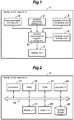
- Figures 1 and 2 are a functional block diagram and a hardware structure diagram of a design assist apparatus 1 according to an embodiment of the present invention, respectively.
- the design assist apparatus 1 executes a process for assisting design of a mechanical device driven by a motor that is feedback-controlled (hereinafter referred to as "design assist process"), and in particular allows the user to easily grasp the influence of the characteristics (parameters of a mathematical model) of a mechanical component forming the mechanical device on the occurrence of abnormal vibration of the mechanical device in conjunction with the design of the mechanical component (including the selection of the mechanical component).
- design assist process a process for assisting design of a mechanical device driven by a motor that is feedback-controlled
- the design assist apparatus 1 essentially consists of a transfer function computing unit 2 that computes a transfer function of the mechanical device (not shown in the drawings) representing the dynamic response characteristics of the mechanical device from a mathematical model consisting of mathematical expressions simulating the characteristics of the mechanical device, an analysis parameter setting unit 3 for setting the range of parameters of the mathematical model of the mechanical component to be analyzed (hereinafter referred to as "analysis target component"), a fixed parameter setting unit 4 for setting parameters of the mathematical models of the mechanical components other than the analysis target component, a vibration mode setting unit 5 for setting the vibration mode of the analysis target component, a stability determination diagram creation unit 6 for computing the poles of the transfer function of the mechanical device, and creating a stability determination diagram including isolines of the real parts of poles in conjunction with one or more vibration modes, and a display unit 7 for accepting the input of various settings (see Figure 9 , for example) by the user and displaying the analysis results such as the stability determination diagram which will be described hereinafter.
- a transfer function computing unit 2 that computes a
- the design assist apparatus 1 consists of a computer provided with per se known hardware and, as shown in Figure 2 , includes one or more processors 11 for executing the design assist process according to design assist software (control program), RAM (Random Access Memory) 12 that functions as a work area for the processors 11, ROM (Read Only Memory) 13 that stores control programs executed by the processors 11 and data, and a network interface (I / F) 14 consisting of a network adapter for allowing the connection of the design assist apparatus 1 with a per se known communication network, which are connected to an input/output bus 15.
- design assist software control program
- RAM Random Access Memory
- ROM Read Only Memory
- I / F network interface
- the design assist apparatus 1 is further provided with peripheral devices such as an input device 16 which may consist of a keyboard and a mouse used by the user to enter various settings in the design assist apparatus 1 in conjunction with the display of analysis results, a display device 17 consisting of an LCD monitor to form the display unit 7, an external storage device 18 consisting of a storage device such as an HDD or a flash memory, and the like.
- peripheral devices such as an input device 16 which may consist of a keyboard and a mouse used by the user to enter various settings in the design assist apparatus 1 in conjunction with the display of analysis results, a display device 17 consisting of an LCD monitor to form the display unit 7, an external storage device 18 consisting of a storage device such as an HDD or a flash memory, and the like.
- the functions of each unit or device of the design assist apparatus 1 shown in Figure 1 can be realized by the processors 11 executing a predetermined control program including design assist software.
- the hardware of the design assist apparatus 1 is not limited to the one shown in Figure 2 as long as the design assist process can be executed, and can be changed as appropriate.
- the design assist apparatus 1 can also be realized by a plurality of computers.
- Figure 3 is a flowchart showing a flow of the design assist process (design assist method) executed by the design assist apparatus 1 (the stability determination diagram creating unit 6).
- the user can select any parameters (two parameters A and B, for instance) of the mathematical model of the mechanical device. These parameters are indicated on the horizontal axis and the vertical axis of the stability determination diagram (see Figure 7 which will be described hereinafter), respectively.
- the numbers n and m by which the horizontal axis and the vertical axis are divided, respectively, are selected by the user (ST101) with the result that the analysis range of parameter A is divided into n increments (ST102), and the analysis range of parameter B is divided into m increments (ST103).
- the division of the horizontal axis and the vertical axis may be performed either linearly or logarithmically. Further, the user does not necessarily have to set the division numbers n and m each time, and the division numbers n and m stored in the external storage device 18 or the like in advance can also be used. Here, if the number of division is large, analysis can be performed with a higher resolution, but the amount of computation load increases. Therefore, the ranges of the numbers of division of the horizontal axis and the vertical axis may be predetermined in advance (by setting upper limit values and/or lower limit values, for example).
- the number of vibration modes of the mechanical device is (DOF - 1).
- the absolute value of the imaginary part of each pole determined in step ST104 corresponds to the vibration frequency of the pole.
- the absolute value of the real part of the pole having the (DOF - N)-th largest absolute value of the imaginary part is stored in the external storage device as Cij (ST105).
- the one whose absolute value of the imaginary part is the (DOF-N)-th largest corresponds to the N-th vibration mode.
- the real part of each pole of the transfer function is related to the stability of the mechanical machine. The mechanical device is stable if the value of the real part is negative, and unstable if the value of the real part is positive.
- a stability determination diagram (graph data containing isolines) including the isolines can be created (ST106).
- the created stability determination diagram is stored in the external storage device 18.
- the stability determination diagram may be a three-dimensional graph based on the parameters Ai and Bj and the value Cij of the real part.
- the user can refer to the above-described stability determination diagram.
- the user may refer to the stability determination diagram preferably via the display of a design assist screen including the stability determination diagram on the display device 17.
- the present invention is not limited to this, and other forms (for example, speech output on the stability determination diagram) may also be used for this purpose.
- the user can easily grasp the influence of the characteristics (parameters) of each mechanical component on the occurrence of abnormal vibration of the mechanical device.
- the user is enabled to prevent the occurrence of abnormal vibration in a newly designed mechanical device in advance, and, in addition, to obtain specific improvement guidance in suppressing the occurrence of vibration in the existing mechanical device if such abnormal vibration is occurring.
- a design assist apparatus 1 and a design assist method according to a preferred embodiment of the present invention are described in the following.
- Figure 4 is a view showing a first mechanical device 21 as an example of application of the design assist process by the design assist apparatus 1
- Figure 5 is a view showing a mechanical model of the first mechanical device 21
- Figure 6 is a block diagram of a control system for an electric motor 23 used in the first mechanical device 21.
- the mechanical device 21 is configured as a rotational drive mechanism of a roller 22 in a printing machine, and is provided with an electric motor 23 for driving the roller 22, and a shaft coupling 24 that connects a shaft 22a extending from one end of the roller 22 with an output shaft 23a of the electric motor 23.
- the analysis target component for the design assist apparatus 1 is the shaft coupling 24.
- the performance of the drive mechanism can be improved by appropriately designing the stiffness and damping characteristics of the shaft coupling 24.
- the mechanical model shown in Figure 5 represents the mechanical characteristics of the rotational drive mechanism of the mechanical device 21.
- the rotational speed of the electric motor 23 is feedback controlled as shown in the block diagram of the control system shown in Figure 6 .
- Tm is the output torque of the electric motor 23
- ⁇ m is the rotational angle of the electric motor 23
- ⁇ r is the rotational angle of the roller 22.
- Table 1 shows the parameters shown in Figures 5 and 6 together with numerical examples used for the analysis.
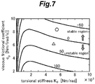
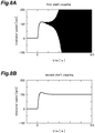
- Figure 7 is a graph showing an example of a stability determination diagram regarding the shaft coupling 24 of the first mechanical device 21 shown in Figure 4 and Figures 8A and 8B show changes in the rotational speed when a target product (which may be a first shaft coupling or second shaft coupling) given as examples of the coupling 24 of the first mechanical device 21.
- a target product which may be a first shaft coupling or second shaft coupling
- the stiffness and damping characteristics (torsional stiffness and motor-roller viscous friction coefficient) of the shaft coupling 24 are used as parameters, and are shown along the horizontal axis and the vertical axis, respectively.
- the numerical values (here, -50, 0, 50, 100) associated with the respective isolines in Figure 7 are the values of the real part of the transfer function regarding the secondary vibration mode of the mechanical device 21.
- abnormal vibration is not likely to be generated in the mechanical device 21 in the stable region where the value of the real part of the transfer function is negative, whereas the possibility of occurrence of abnormal vibration in the mechanical device 21 is high in the unstable region where the value of the real part is positive.
- the stability determination diagram is not limited to that shown in Figure 7 , and the horizontal axis and the vertical axis shown in Figure 7 may be interchanged with each other, for example.
- Figures 8A and 8B show changes in the rotational speed of the roller 22 when the rotational speed of the motor 23 is increased from zero to 100 rpm in the mechanical device 21 to which the first and second shaft couplings are applied as the shaft coupling 24, respectively.
- the values of the stiffness and damping characteristics of the first coupling are located in the unstable region of the stability determination diagram, as indicated by a triangle ( ⁇ ) in Figure 7 .
- the values of the torsional stiffness and the viscous damping characteristics of the second coupling are located in the stable region of the stability determination diagram, as indicated by a circle (o) in Figure 7 .
- the "target product" used in the present invention can be selected from existing products such as commercial products, but may additionally be a mechanical component which is planned to be newly designed and manufactured.
- the user can easily grasp the influence of the characteristics of the shaft coupling 24 (the stiffness and damping characteristics, in this case) on the vibration of the mechanical device 21 from the above-described stability determination diagram.
- the user can prevent abnormal vibration from occurring in the mechanical device 21 by designing (including selecting) the shaft coupling 24 so that the values of the stiffness and the damping characteristic are located in the stable region.
- the user can obtain specific improvement guidelines on the stiffness and damping characteristics of the shaft coupling 24 for suppressing the generation of the vibration.
- Figure 9 is a view showing an example of a GUI (Graphical User Interface) screen 30 created by the design assist software installed in the design assist apparatus 1 in conjunction with the design assist operation for the first mechanical device 21.
- GUI Graphic User Interface
- the GUI screen 30 includes an analysis parameter setting field 31 that enables input operation by the user for selecting the range of parameters of the analysis target component (here, the stiffness and damping characteristics of the coupling 24, etc.) set by the analysis parameter setting unit 3.
- a fixed parameter setting field 32 enables input operation by the user for selecting the parameters (such as a velocity loop proportional gain Kvp, a velocity loop integral gain Kvi, a viscous friction coefficient of the electric motor, a viscous friction coefficient of roller, a motor-roller viscous damping coefficient, etc.) of mechanical components other than the analysis target component which are set by the fixed parameter setting unit 4.
- an analysis result output field 33 displays a stability determination diagram 41 corresponding to the diagram shown in Figure 7 , and a three-dimensional graph 42 thereof according to a prescribed operation by the user.
- the three-dimensional graph 42 can be displayed from any desired viewpoint by checking "rotation ON” on the GUI screen.
- the display of "rotation ON” may be omitted so that rotation may be possible at all times, or the viewpoint may be fixed.
- the above-described transfer function computation unit 2 is a part of the function of the design assist software, and, those of the parameters of the mechanical components which are not required to be changed are stored in the external storage device 18 in advance as data belonging to the design assist software.
- the vibration mode of the mechanical device 21 is one, a vibration mode setting field as shown in Figure 17 which will be described hereinafter is not necessary, and the above-described vibration mode setting unit 5 may be omitted.
- the analysis result output field 33 may display a root locus diagram 45 created from the parameters of the shaft coupling 24 by using a per se known method.
- Figure 10 is a view showing a second mechanical device 51 given as another example of the application of the design assist process by the design assist apparatus 1
- Figure 11 is a view showing a mechanical model of the mechanical device 51.
- the second mechanical device 51 reference should be made to the above description of the first mechanical device 21 for matters that are not particularly mentioned in the following.
- the mechanical device 51 is configured as a feed drive mechanism of a manufacturing apparatus (for example, a machine tool), and includes a ball screw 52, a table 54 attached to a nut 53 of the ball screw 52, a support bearing supporting a screw shaft 55 of the ball screw 52, a servomotor 57 for driving the ball screw 52, and a shaft coupling 58 connecting an end 55a of the screw shaft 55 with an output shaft 57a of the servomotor 57.
- the mechanical device 51 is enabled to convert the rotational movement of the servomotor 57 into a linear movement of the table 54 via the screw shaft 55 and the nut 53.
- the components to be analyzed by the design assist apparatus 1 are the shaft coupling 58 and the support bearing 56.
- the performance of the feed drive mechanism of this mechanical device 51 can be improved by appropriately designing the stiffness and damping characteristics of the shaft coupling 58 and the support bearing 56.
- the mechanical model shown in Figure 11 represents mechanical characteristics of the drive mechanism of the mechanical device 21.
- Tm is the output torque of the servomotor 57
- ⁇ m is the rotational angle of the servomotor 57
- ⁇ s is the rotational angle of the screw shaft 55
- xs is the axial displacement of the screw shaft 55
- xt is the axial displacement of the table 54.
- Table 2 shows the parameters shown in Figure 11 together with numerical examples used for the analysis.
- Figures 12A and 12B are stability determination diagrams regarding the primary vibration mode and the secondary vibration mode of the support bearing 56 which is one of the mechanical components of the second mechanical device 51 shown in Figure 10 , respectively.
- Figures 13A and 13B show the changes in the speed in cases where target products (first and second support bearings) that are candidates for the support bearing 56 of the second mechanical device 51 are used.
- the stiffness and damping characteristics (axial stiffness and axial viscous damping coefficient) of the support bearing 56 are used as parameters, and are indicated along the horizontal axis and the vertical axis, respectively. Since the mechanical model of the mechanical device 51 shown in Figure 11 has four degrees of freedom, the number of vibration modes is three. Here, the stability determination diagram is shown in regards to only two of the vibration modes (the primary vibration mode shown in Figure 12A , and the secondary vibration mode shown in Figure 12B ).
- Figures 13A and 13B show the response (speed change) of the mechanical device 51 to which the first and second support bearings are applied as the support bearing 56, respectively, when the speed command of the servomotor 57 is changed in a stepwise manner.
- the values of the axial stiffness and the axial viscous damping coefficient of the first support bearing are indicated by a triangle mark ( ⁇ ) in Figures 12A and 12B , and are located in the stable region for the primary vibration mode shown in Figure 12A , but are located in the unstable region for the secondary vibration mode shown in Figure 12B .
- the values of the axial stiffness and the axial viscous damping coefficient of the second support bearing are shown by a circle mark (o) in Figures 12A and 12B , and, contrary to the first support bearing, are located in the unstable region for the primary vibration mode shown in Figure 12A , but in the stable region for the secondary vibration mode shown in Figure 12B .
- the user can easily grasp the influence of the characteristics of the support bearing 56 (here, the axial stiffness and the viscous damping coefficient in the axial direction) of the mechanical device 51 on the vibration of the mechanical device 51 in the primary vibration mode and the secondary vibration mode.
- the stability of the mechanical component of a mechanical device having two or more vibration modes can be easily determined not only after manufacture of the mechanical device but also at the time of designing the mechanical device.
- Figures 14A and 14B are examples of stability determination diagrams regarding the primary vibration mode and the secondary vibration mode of the shaft coupling 58 which is one of the mechanical components of the second mechanical device 51 shown in Figure 10 , respectively.
- Figures 15A and 15B are graphs showing changes in the speed when the target products (the first shaft coupling and the second shaft coupling) representing the shaft coupling 58 of the second mechanical device 51, respectively, are used.
- Figure 16 is a graph for a modification of the stability determination diagrams shown in Figures 14A and 14B .
- the design assist apparatus 1 and the design assist method associated therewith it is possible to freely select the analysis target and the vibration mode when creating the stability determination diagram. Also, similarly as in the case of Figure 7 described above, as shown in Figures 14A and 14B , the possibility of abnormal vibration occurring in the mechanical device 5 is low in the stable region where the value of the real part of the transfer function is negative, and, on the other hand, there is a high possibility that abnormal vibration occurs in the mechanical device 51 in the unstable region where the value of the real part is positive.
- Figures 15A and 15B show the responses of the mechanical device 51 in the cases of using the first shaft coupling and the second shaft coupling, respectively, when the speed command of the servomotor 57 is changed in a stepwise manner.
- the values of the axial stiffness and the axial viscous damping coefficient of the first support bearing are indicated by a triangle mark ( ⁇ ) in Figures 14A and 14B , and are located in the stable region for the primary vibration mode shown in Figure 14A , but are located in the unstable region for the secondary vibration mode shown in Figure 14B .
- the axial stiffness and the value of the viscous damping coefficient in the axial direction of the second coupling are indicated by a circle mark (o) in Figures 14A and 14B , and the mechanical device 51 is in the stable region for both the primary vibration mode shown in Figure 14A and the secondary vibration mode shown in Figure 14B .
- vibration occurs at a higher frequency than in the second support bearing shown in Figure 15B .
- the second shaft coupling shown in Figure 15B it can be seen that the response is not oscillatory, and the second mechanical device 51 can be used in a normal fashion.
- the overall performance of the feed drive mechanism can be improved by designing the characteristics of the support bearing 56 so as to be located in the stable region of the stability determination diagram for the primary vibration mode, and then so as to be located in the stable region of the stability determination diagram for the secondary vibration mode. Also, if the stiffness of the support bearing 56 is selected to be intermediate between the value of the first support bearing and the value of the second support bearing, the values can be located in the stable region of the stability determination diagram for both the primary and secondary vibration modes. It is known that the axial stiffness of the support bearing can be adjusted by changing the preload amount of the bearing.
- the user can easily grasp the influence of a plurality of analysis target components on the vibration of the mechanical device 51 by using the design assist apparatus 1 and the design assist method associated therewith. Also, the user can know the stiffness and damping characteristics of the mechanical components that are optimum for improving the performance of the mechanical device 51, and can design the mechanical components (including the selection of the mechanical components) so as to improve the performance of the mechanical device.
- the stability determination diagrams were created based on the characteristics of each separate mechanical component (support bearing 56, shaft coupling 58) in Figures 12 and Figures 14 , but it is also possible to create a stability determination diagram based on the characteristics of a plurality of mechanical components (for instance, by indicating the stiffness of the support bearing 56 along the horizontal axis, and the stiffness of the shaft coupling 58 along the vertical axis).
- at least one of the horizontal axis and the vertical axis of the above described stability determination diagram may indicate a servo gain of the control system for the servomotor 57, the lead of the ball screw 52, or the inertia moment and mass of a mechanical component.
- a stability determination diagram was created for each of a plurality of vibration modes, but it is also possible to create a single stability determination diagram including a plurality of stability determination diagrams corresponding to the respective vibration modes which are superimposed one over another to be displayed on the display unit 7.
- the stability determination diagram shown in Figure 16 contains the isolines relating to the first vibration mode and the second vibration mode shown in Figures 12A and 12B , and define a stable region (see the dark region in Figure 16 ) and an unstable region by taking into account the two vibration modes.
- the user can thus more reliably grasp the influence of the characteristics of the support bearing 56 on the occurrence of abnormal vibration of the mechanical device by using the stability determination diagram based on the multiple vibration modes.
- the design assist apparatus 1 and the design assist method associated therewith it is also possible to create a single stability determination diagram in which the stability determination diagrams created for each of three or more vibration modes are superimposed one over another.
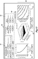
- Figure 17 is a diagram showing an example of the screen 60 of the GUI created by executing the design assist software on the design assist apparatus 1 regarding the design assist of the second mechanical device 51.
- the GUI screen 60 includes an analysis parameter setting field 61 that allows a manual input by the user of the ranges of the parameters (here, the axial stiffness and viscous damping in the axial direction of the support bearing 56) of the analysis target components determined by the analysis parameter setting unit 3. The user can appropriately change the analysis target component in the analysis parameter setting field 61.
- the GUI screen 60 further includes a fixed parameter setting field 62 that allows a manual input by the user of the parameters of mechanical components other than the analysis target components set by the fixed parameter setting unit 4 such as the velocity loop proportional gain Kvp, the velocity loop integral gain Kvi, the axial stiffness, torsional stiffness and viscous damping coefficient of the shaft coupling 58, the axial stiffness and viscous damping coefficient of the bearing, the axial stiffness and the viscous friction coefficient of the nut 53.
- the GUI screen 60 also includes a vibration mode setting field 64 that allows the user to perform an input operation regarding the vibration mode of the analysis target component set by the vibration mode setting unit 5.
- the analysis result output field 63 includes a stability determination diagram 71 corresponding to Figure 12B and a three-dimensional graph 72 associated therewith.
- the three-dimensional graph can be displayed from any viewpoint by checking "rotation ON" on the GUI screen.
- the display of "rotation ON” may be omitted so that rotation may always be possible, or the viewpoint may be fixed.
- the present invention can be applied not only to the case where the applied mechanical device has only one vibration mode but also to cases where the mechanical device has two or more vibration modes with an even greater advantage because the parameters of the mechanical components can be selected so that a stable operation can be ensured in each of the vibration modes.
- the present invention provides not only measures against abnormal vibration which is found after the mechanical device is manufactured, but also allows various parameters of the mechanical components to be appropriately set in advance of actually manufacturing the mechanical device.
- the design assist apparatus and the design assist method according to the present invention are not limited to the examples described above in the application thereof, and can be applied, for example, to drive mechanisms of various other mechanical devices such as semiconductor manufacturing devices, power steering devices, lift devices (control surface devices) for aircraft, and industrial robots.
- the various elements of the design assist apparatus, the design assist method, and the design assist program according to the present invention described above in terms of specific embodiments are not entirely essential for the present invention but can be appropriately omitted and substituted without departing from the scope of the present invention.
Landscapes
- Engineering & Computer Science (AREA)
- Physics & Mathematics (AREA)
- General Physics & Mathematics (AREA)
- Automation & Control Theory (AREA)
- Theoretical Computer Science (AREA)
- Geometry (AREA)
- Evolutionary Computation (AREA)
- Computer Hardware Design (AREA)
- General Engineering & Computer Science (AREA)
- Power Engineering (AREA)
- Pure & Applied Mathematics (AREA)
- Medical Informatics (AREA)
- Mathematical Analysis (AREA)
- Computational Mathematics (AREA)
- Health & Medical Sciences (AREA)
- Artificial Intelligence (AREA)
- Computer Vision & Pattern Recognition (AREA)
- Mathematical Optimization (AREA)
- Software Systems (AREA)
- Control Of Electric Motors In General (AREA)
- Testing Of Devices, Machine Parts, Or Other Structures Thereof (AREA)
- Feedback Control In General (AREA)
- Stored Programmes (AREA)
- Mirrors, Picture Frames, Photograph Stands, And Related Fastening Devices (AREA)
Abstract
Description
- The present invention relates to a design assist apparatus, a design assist method, and a design assist program configured to support the design of a mechanical device which is driven by a feedback controlled electric motor.
- In a feed drive mechanism that converts the rotational movement of a servomotor controlled by a feedback control system into a linear movement of a table via a ball screw and a nut, for example, it is known that the responsiveness and the precision of the rotational movement of the servomotor increases as the gain constant of the feedback control system is increased. However, it is also known that if the gain constant is excessively large, an incidence of abnormal vibration may occur at a natural frequency (eigenfrequency) which depends on the mass and stiffness of various parts of the feed drive mechanism.
- Conventionally, as a technology for determining a suitable property of a control system, it is known to create a root locus diagram according to the characteristics of the corresponding mechanical system. See Non-Patent
Document 1. It is also known as a method for improving the general performance of a mechanical device to design the various components thereof by analyzing the relationship between the moment of inertia and the stiffness of the mechanical components, and the servo stiffness which is given as an index of performance of the mechanical device. See Non-PatentDocument 2. It is also known to simulate the properties of the mechanical device according to a model thereof for the purpose of assisting the optimum design of the mechanical device. SeePatent Document 1. - Patent Document 1:
JP2008-102714A -
- Non-Patent Document 1: "Design and Control of Precision Positioning and Feed Drive systems", Atsushi Matsubara, Morikita Publishing, 2008
- Non-Patent Document 2: "A Study on the Total Tuning of Feed Drive System in NC Machine Tools (3rd report) - Single Axis Mechanical Parameter Tuning", Yoshiaki Kakino, Atsushi Matsubara, Daisuke Ueda, Hideo Nakagawa, Torao Takeshita, Hisaichi Maruyama, Journal of the Japan Society for Precision Engineering, Vol. 62, No. 3, (1996), pp.423-427
- Whereas the ultimate performance of a mechanical device is limited by the characteristics of the mechanical system thereof, the prior art disclosed in Non-Patent
Document 1 is related strictly to the control system, and provides no considerations for the mechanical device itself or the mechanical components thereof. The prior art disclosed in Non-PatentDocument 2 considers only the first order natural frequency, and fails to provide to the user adequate information on the vibrations that may occur in the mechanical device. The prior art disclosed inPatent Document 1 provides a design that optimizes the servo gain when forming a desired shape by simultaneously actuating a plurality of feed drive mechanisms, but fails to provide a guidance as to how the property of the mechanical system should be designed in order to improve the performance of the mechanical system. - When a user designs (or selects) mechanical components forming a mechanical device, it is desired that the user is enabled to know how the properties of the individual mechanical components affect the generation of abnormal vibrations of the mechanical device. However, the prior art mentioned above fails to address such needs or the conveniences of the user.
- In view of such a problem of the prior art, a primary object of the present invention is to provide a design assist apparatus, a design assist method, and a design assist program configured to support the design of a mechanical device driven by a feedback controlled electric motor in such a manner that the user is enabled to easily know how the properties of the mechanical components affect the generation of abnormal vibrations of the mechanical device.
- To achieve such an object, a first aspect of the present invention provides a design assist apparatus (1) provided with a processor (11) configured to execute a process of assisting design of a mechanical device (21, 51) driven by a feedback controlled electric motor (23, 57), wherein the processor is configured to set a plurality of parameters of a mathematical model of an analysis target component selected from one or more mechanical components (24, 56, 58) forming the mechanical device, compute a pole of a transfer function of the mechanical device associated with one or more vibration modes of the mechanical device according to the parameters, and create a stability determination diagram including an isoline of a real part of the pole of the transfer function.
- Thereby, in designing (or selecting) the mechanical component forming the mechanical device, the user is enabled to readily know how the properties (parameters) of the mechanical component affect the generation of abnormal vibrations of the mechanical device. As a result, the occurrence of abnormal vibration in the mechanical device can be prevented in a preemptive manner, and the user can obtain specific guidelines for improvement regarding the properties of the mechanical component that may be required for suppressing the abnormal vibration which has already occurred in the mechanical device.
- According to a second aspect of the present invention, the design assist apparatus further comprises a display unit for displaying the stability determination diagram (41, 71).
- Thus, it is possible for the user to easily visually grasp the influence of the characteristics of the mechanical component on the occurrence of abnormal vibration of the mechanical device by using the stability determination diagram displayed on the display unit.
- According to a third aspect of the present invention, when the mechanical device has a plurality of vibrations modes, the stability determination diagram created by the processor includes isolines of the real parts of the poles of the transfer function corresponding to the respective vibrations modes.
- Thereby, the user can grasp the influence of the characteristics of the mechanical component on the occurrence of the abnormal vibration of the mechanical device in an even more reliable manner by using the stability determination diagram based on the vibration modes displayed on the display unit.
- According to a fourth aspect of the present invention, the parameters include those related to stiffness and damping characteristics of the mechanical component.
- Thereby, the user can grasp the influence of the characteristics of the mechanical component on the occurrence of the abnormal vibration of the mechanical device in an appropriate manner.
- According to a fifth aspect of the present invention, when the poles are arranged in descending order of imaginary parts of the poles of the transfer function, the isolines are generated for the real part of the pole which is lower in the descending order by a difference between a number of freedom of the mathematical model and a number of the vibration modes.
- Thereby, the stability determination diagram including isolines of real parts of the poles of the transfer function can be created in an appropriate manner.
- According to a sixth aspect of the present invention, the processor is configured to create the stability determination diagram so as to include a marking indicating the parameters of the one or more target products which may be a candidate for the mechanical component.
- Thereby, the user is enabled to grasp the influence of the characteristics (parameters) of the target product which is a candidate for the mechanical component on the occurrence of abnormal vibration of the mechanical device in selecting the mechanical component. As a result, the user is enabled to select the mechanical component so as to prevent the occurrence of abnormal vibration in the mechanical device, or to suppress the abnormal vibration which has already occurred in the mechanical device.
- A seventh aspect of the present invention provides a design assist method for assisting design of a mechanical device (21, 51) driven by a feedback controlled electric motor (23, 57), comprising the steps of setting a plurality of parameters of a mathematical model of an analysis target component selected from one or more mechanical components (24, 56, 58) forming the mechanical device, computing a pole of a transfer function of the mechanical device associated with one or more vibration modes of the mechanical device according to the parameters, and creating a stability determination diagram including an isoline of a real part of the pole of the transfer function.
- Thereby, in designing (or selecting) the mechanical component forming the mechanical device, the user is enabled to readily know how the properties (parameters) of the mechanical component affect the generation of abnormal vibrations of the mechanical device. As a result, the occurrence of abnormal vibration in the mechanical device can be prevented in a preemptive manner, and the user can obtain specific guidelines for improvement regarding the properties of the mechanical component that may be required for suppressing the abnormal vibration which has already occurred in the mechanical device.
- An eighth aspect of the present invention provides a design assist program for executing a process for assisting design of a mechanical device (21, 51) driven by a feedback controlled electric motor (23, 57), characterized by causing a computer (1) to execute the procedures of setting a plurality of parameters of a mathematical model of an analysis target component selected from one or more mechanical components (24, 56, 58) forming the mechanical device, computing a pole of a transfer function of the mechanical device associated with one or more vibration modes of the mechanical device according to the parameters, and creating a stability determination diagram including an isoline of a real part of the pole of the transfer function.
- Thereby, in designing (or selecting) the mechanical component forming the mechanical device, the user is enabled to readily know how the properties (parameters) of the mechanical component affect the generation of abnormal vibrations of the mechanical device. As a result, the occurrence of abnormal vibration in the mechanical device can be prevented in a preemptive manner, and the user can obtain specific guidelines for improvement regarding the properties of the mechanical component that may be required for suppressing the abnormal vibration which has already occurred in the mechanical device.
- As described above, according to the present invention, in the design of a mechanical component constituting a mechanical device driven by an electric motor under feedback control, the user can easily grasp the influences of the characteristics of the mechanical component on the occurrence of abnormal vibration of the mechanical device.
-
-
Figure 1 is a functional block diagram of a design assist apparatus; -
Figure 2 is a hardware structure diagram of the design assist apparatus; -
Figure 3 is a flowchart showing the flow of the design assist process executed by the design assist apparatus; -
Figure 4 is a view showing a first mechanical device given as an example of application of the design assist process; -
Figure 5 is a mechanical model of the first mechanical device; -
Figure 6 is a block diagram of the control system for the electric motor of the first mechanical device; -
Figure 7 is an example of stability determination diagram for a shaft coupling of the first mechanical device; -
Figure 8 show graphs showing changes in the rotational speed in target products given as candidates for the shaft coupling of the first mechanical device (A: first shaft coupling, B: second shaft coupling); -
Figure 9 is a view of an example of a GUI screen generated by design assist software executed by the design assist apparatus in connection with the design of the first mechanical device; -
Figure 10 is a view showing a second mechanical device given as an example of application of the design assist process; -
Figure 11 is a diagram showing a mechanical model of the second mechanical device; -
Figure 12 shows graphs associated with examples of stability determination diagrams for a support bearing of the second mechanical device (A: primary vibration mode, B: secondary vibration mode); -
Figure 13 shows graphs showing changes in the rotational speed when target products given as candidates for the support bearing of the second mechanical device (A: first support bearing, B: second support bearing); -
Figure 14 shows diagrams showing examples of stability determination diagrams for the shaft coupling of the second mechanical device (A: first order vibration mode, B: second order vibration mode); -
Figure 15 shows graphs showing changes in the rotational speed when target products given as candidates for the shaft coupling of the second mechanical device (A: first shaft coupling, B: second shaft coupling); -
Figure 16 shows a modification of the stability determination diagram shown inFigure 14 ; and -
Figure 17 is a view of an example of a GUI screen generated by design assist software executed by the design assist apparatus in connection with the design of the second mechanical device. - The present invention is described in the following in terms of specific embodiment with reference to the appended drawings.
-
Figures 1 and 2 are a functional block diagram and a hardware structure diagram of adesign assist apparatus 1 according to an embodiment of the present invention, respectively. - The
design assist apparatus 1 executes a process for assisting design of a mechanical device driven by a motor that is feedback-controlled (hereinafter referred to as "design assist process"), and in particular allows the user to easily grasp the influence of the characteristics (parameters of a mathematical model) of a mechanical component forming the mechanical device on the occurrence of abnormal vibration of the mechanical device in conjunction with the design of the mechanical component (including the selection of the mechanical component). - As shown in
Figure 1 , the design assistapparatus 1 essentially consists of a transferfunction computing unit 2 that computes a transfer function of the mechanical device (not shown in the drawings) representing the dynamic response characteristics of the mechanical device from a mathematical model consisting of mathematical expressions simulating the characteristics of the mechanical device, an analysisparameter setting unit 3 for setting the range of parameters of the mathematical model of the mechanical component to be analyzed (hereinafter referred to as "analysis target component"), a fixedparameter setting unit 4 for setting parameters of the mathematical models of the mechanical components other than the analysis target component, a vibrationmode setting unit 5 for setting the vibration mode of the analysis target component, a stability determinationdiagram creation unit 6 for computing the poles of the transfer function of the mechanical device, and creating a stability determination diagram including isolines of the real parts of poles in conjunction with one or more vibration modes, and adisplay unit 7 for accepting the input of various settings (seeFigure 9 , for example) by the user and displaying the analysis results such as the stability determination diagram which will be described hereinafter. - The
design assist apparatus 1 consists of a computer provided with per se known hardware and, as shown inFigure 2 , includes one ormore processors 11 for executing the design assist process according to design assist software (control program), RAM (Random Access Memory) 12 that functions as a work area for theprocessors 11, ROM (Read Only Memory) 13 that stores control programs executed by theprocessors 11 and data, and a network interface (I / F) 14 consisting of a network adapter for allowing the connection of the design assistapparatus 1 with a per se known communication network, which are connected to an input/output bus 15. - The
design assist apparatus 1 is further provided with peripheral devices such as aninput device 16 which may consist of a keyboard and a mouse used by the user to enter various settings in the design assistapparatus 1 in conjunction with the display of analysis results, adisplay device 17 consisting of an LCD monitor to form thedisplay unit 7, anexternal storage device 18 consisting of a storage device such as an HDD or a flash memory, and the like. The functions of each unit or device of the design assistapparatus 1 shown inFigure 1 can be realized by theprocessors 11 executing a predetermined control program including design assist software. - The hardware of the design assist
apparatus 1 is not limited to the one shown inFigure 2 as long as the design assist process can be executed, and can be changed as appropriate. For example, the design assistapparatus 1 can also be realized by a plurality of computers. -
Figure 3 is a flowchart showing a flow of the design assist process (design assist method) executed by the design assist apparatus 1 (the stability determination diagram creating unit 6). - In the design assist
apparatus 1, the user can select any parameters (two parameters A and B, for instance) of the mathematical model of the mechanical device. These parameters are indicated on the horizontal axis and the vertical axis of the stability determination diagram (seeFigure 7 which will be described hereinafter), respectively. - Upon starting of the design assist process, the numbers n and m by which the horizontal axis and the vertical axis are divided, respectively, are selected by the user (ST101) with the result that the analysis range of parameter A is divided into n increments (ST102), and the analysis range of parameter B is divided into m increments (ST103). The division of the horizontal axis and the vertical axis may be performed either linearly or logarithmically. Further, the user does not necessarily have to set the division numbers n and m each time, and the division numbers n and m stored in the
external storage device 18 or the like in advance can also be used. Here, if the number of division is large, analysis can be performed with a higher resolution, but the amount of computation load increases. Therefore, the ranges of the numbers of division of the horizontal axis and the vertical axis may be predetermined in advance (by setting upper limit values and/or lower limit values, for example). - The parameters Ai (i = 1 to n) and Bj (j = 1 to m) to be analyzed (in other words, values of the parameters A and B that are varied according to the respective division numbers n and m) are substituted into the transfer function, and the poles are sequentially computed (ST104). At this time, the poles of the transfer function can be obtained as the roots of the denominator polynomial of the transfer function.
- Here, assuming that the degree of freedom of the mechanical device model is DOF, the number of vibration modes of the mechanical device is (DOF - 1). The absolute value of the imaginary part of each pole determined in step ST104 corresponds to the vibration frequency of the pole. When the N-th order vibration mode is to be analyzed, the absolute value of the real part of the pole having the (DOF - N)-th largest absolute value of the imaginary part is stored in the external storage device as Cij (ST105). Thus, where the N-th vibration mode is to be analyzed, among the poles determined in step ST104, the one whose absolute value of the imaginary part is the (DOF-N)-th largest corresponds to the N-th vibration mode. The real part of each pole of the transfer function is related to the stability of the mechanical machine. The mechanical device is stable if the value of the real part is negative, and unstable if the value of the real part is positive.
- Then, by computing isolines on a graph having A along the horizontal axis and B along the vertical axis in regard to the value Cij of the real part obtained in step ST105, a stability determination diagram (graph data containing isolines) including the isolines can be created (ST106). The created stability determination diagram is stored in the
external storage device 18. The stability determination diagram may be a three-dimensional graph based on the parameters Ai and Bj and the value Cij of the real part. - As will be described hereinafter, in the design of the mechanical components (including the selection of the mechanical components) that constitute the mechanical device, the user can refer to the above-described stability determination diagram. The user may refer to the stability determination diagram preferably via the display of a design assist screen including the stability determination diagram on the
display device 17. However, the present invention is not limited to this, and other forms (for example, speech output on the stability determination diagram) may also be used for this purpose. - Thus, the user can easily grasp the influence of the characteristics (parameters) of each mechanical component on the occurrence of abnormal vibration of the mechanical device. As a result, the user is enabled to prevent the occurrence of abnormal vibration in a newly designed mechanical device in advance, and, in addition, to obtain specific improvement guidance in suppressing the occurrence of vibration in the existing mechanical device if such abnormal vibration is occurring.
- A
design assist apparatus 1 and a design assist method according to a preferred embodiment of the present invention are described in the following. -
Figure 4 is a view showing a firstmechanical device 21 as an example of application of the design assist process by the design assistapparatus 1, andFigure 5 is a view showing a mechanical model of the firstmechanical device 21.Figure 6 is a block diagram of a control system for anelectric motor 23 used in the firstmechanical device 21. - As shown in
Figure 4 , themechanical device 21 is configured as a rotational drive mechanism of aroller 22 in a printing machine, and is provided with anelectric motor 23 for driving theroller 22, and ashaft coupling 24 that connects ashaft 22a extending from one end of theroller 22 with anoutput shaft 23a of theelectric motor 23. In this case, the analysis target component for the design assistapparatus 1 is theshaft coupling 24. The performance of the drive mechanism can be improved by appropriately designing the stiffness and damping characteristics of theshaft coupling 24. - The mechanical model shown in
Figure 5 represents the mechanical characteristics of the rotational drive mechanism of themechanical device 21. The rotational speed of theelectric motor 23 is feedback controlled as shown in the block diagram of the control system shown inFigure 6 . Here, Tm is the output torque of theelectric motor 23, θm is the rotational angle of theelectric motor 23, and θr is the rotational angle of theroller 22. Table 1 shows the parameters shown inFigures 5 and 6 together with numerical examples used for the analysis.Table 1 parameters value unit Jm moment of inertia of motor 0.0224 kgm2 Jr moment of inertia of roller 0.638 kgm2 Kθ motor-roller torsional stiffness 4.5×10⁵ Nm/rad Cm viscous friction coefficient of motor 5×10⁻⁴ Nm/(rad/s) Cr viscous friction coefficient of roller 2×10⁻³ Nm/(rad/s) Cθ motor-roller viscous damping coefficient 8 Nm/(rad/s) Kvp velocity loop proportional gain 70 - Kvi velocity loop integral gain 20 - - From the mechanical model shown in
Figure 5 , the following equation of motion is obtained, and from this equation of motion and the block diagram shown inFigure 6 , the transfer function of the entiremechanical device 21 can be computed based on a per se known method.
-
Figure 7 is a graph showing an example of a stability determination diagram regarding theshaft coupling 24 of the firstmechanical device 21 shown inFigure 4 andFigures 8A and 8B show changes in the rotational speed when a target product (which may be a first shaft coupling or second shaft coupling) given as examples of thecoupling 24 of the firstmechanical device 21. - In the stability determination diagram shown in
Figure 7 , the stiffness and damping characteristics (torsional stiffness and motor-roller viscous friction coefficient) of theshaft coupling 24 are used as parameters, and are shown along the horizontal axis and the vertical axis, respectively. The numerical values (here, -50, 0, 50, 100) associated with the respective isolines inFigure 7 are the values of the real part of the transfer function regarding the secondary vibration mode of themechanical device 21. In this example, except in the region where the torsional stiffness is relatively small (a region where the torsional stiffness is less than 2.0 x 10⁵, for example), abnormal vibration is not likely to be generated in themechanical device 21 in the stable region where the value of the real part of the transfer function is negative, whereas the possibility of occurrence of abnormal vibration in themechanical device 21 is high in the unstable region where the value of the real part is positive. The stability determination diagram is not limited to that shown inFigure 7 , and the horizontal axis and the vertical axis shown inFigure 7 may be interchanged with each other, for example. -
Figures 8A and 8B show changes in the rotational speed of theroller 22 when the rotational speed of themotor 23 is increased from zero to 100 rpm in themechanical device 21 to which the first and second shaft couplings are applied as theshaft coupling 24, respectively. - Here, the values of the stiffness and damping characteristics of the first coupling are located in the unstable region of the stability determination diagram, as indicated by a triangle (Δ) in
Figure 7 . On the other hand, the values of the torsional stiffness and the viscous damping characteristics of the second coupling are located in the stable region of the stability determination diagram, as indicated by a circle (o) inFigure 7 . The "target product" used in the present invention can be selected from existing products such as commercial products, but may additionally be a mechanical component which is planned to be newly designed and manufactured. - As shown in
Figure 8A , when the first shaft coupling having the values of stiffness and damping characteristics that are located in the unstable region is applied to themechanical device 21, abnormal vibration occurs as theroller 22 rotates. It can be understood that the normal use of themechanical device 21 is difficult. On the other hand, as shown inFigure 8B , when the second coupling having the values of stiffness and damping characteristics that are located in the stable region is applied to themechanical device 21, theroller 22 of themechanical device 21 can rotate in a normal manner. - Thus, the user can easily grasp the influence of the characteristics of the shaft coupling 24 (the stiffness and damping characteristics, in this case) on the vibration of the
mechanical device 21 from the above-described stability determination diagram. As a result, the user can prevent abnormal vibration from occurring in themechanical device 21 by designing (including selecting) theshaft coupling 24 so that the values of the stiffness and the damping characteristic are located in the stable region. In addition, when abnormal vibration should occur in themechanical device 21, the user can obtain specific improvement guidelines on the stiffness and damping characteristics of theshaft coupling 24 for suppressing the generation of the vibration. By using the present invention, it is possible to display a guideline for ensuring a stable operation of a mechanical component such as a shaft coupling in such a manner as to allow the user to readily make necessary decisions. Therefore, a highly advantageous effect can be achieved. -
Figure 9 is a view showing an example of a GUI (Graphical User Interface)screen 30 created by the design assist software installed in the design assistapparatus 1 in conjunction with the design assist operation for the firstmechanical device 21. - As shown in
Figure 9 , theGUI screen 30 includes an analysisparameter setting field 31 that enables input operation by the user for selecting the range of parameters of the analysis target component (here, the stiffness and damping characteristics of thecoupling 24, etc.) set by the analysisparameter setting unit 3. A fixedparameter setting field 32 enables input operation by the user for selecting the parameters (such as a velocity loop proportional gain Kvp, a velocity loop integral gain Kvi, a viscous friction coefficient of the electric motor, a viscous friction coefficient of roller, a motor-roller viscous damping coefficient, etc.) of mechanical components other than the analysis target component which are set by the fixedparameter setting unit 4. Further, an analysisresult output field 33 displays a stability determination diagram 41 corresponding to the diagram shown inFigure 7 , and a three-dimensional graph 42 thereof according to a prescribed operation by the user. The three-dimensional graph 42 can be displayed from any desired viewpoint by checking "rotation ON" on the GUI screen. The display of "rotation ON" may be omitted so that rotation may be possible at all times, or the viewpoint may be fixed. - The above-described transfer
function computation unit 2 is a part of the function of the design assist software, and, those of the parameters of the mechanical components which are not required to be changed are stored in theexternal storage device 18 in advance as data belonging to the design assist software. In this particular case, since the vibration mode of themechanical device 21 is one, a vibration mode setting field as shown inFigure 17 which will be described hereinafter is not necessary, and the above-described vibrationmode setting unit 5 may be omitted. - In the design assist
apparatus 1, by using thisGUI screen 40, input of various settings by the user can be made, and output (such as a stability determination diagram) of an analysis result to the user can also be made. As such an output of an analysis result, the analysisresult output field 33 may display a root locus diagram 45 created from the parameters of theshaft coupling 24 by using a per se known method. -
Figure 10 is a view showing a secondmechanical device 51 given as another example of the application of the design assist process by the design assistapparatus 1, andFigure 11 is a view showing a mechanical model of themechanical device 51. In regard to the secondmechanical device 51, reference should be made to the above description of the firstmechanical device 21 for matters that are not particularly mentioned in the following. - As shown in
Figure 10 , themechanical device 51 is configured as a feed drive mechanism of a manufacturing apparatus (for example, a machine tool), and includes aball screw 52, a table 54 attached to anut 53 of theball screw 52, a support bearing supporting ascrew shaft 55 of theball screw 52, aservomotor 57 for driving theball screw 52, and ashaft coupling 58 connecting an end 55a of thescrew shaft 55 with an output shaft 57a of theservomotor 57. By using this configuration, themechanical device 51 is enabled to convert the rotational movement of theservomotor 57 into a linear movement of the table 54 via thescrew shaft 55 and thenut 53. Here, the components to be analyzed by the design assistapparatus 1 are theshaft coupling 58 and thesupport bearing 56. The performance of the feed drive mechanism of thismechanical device 51 can be improved by appropriately designing the stiffness and damping characteristics of theshaft coupling 58 and thesupport bearing 56. - The mechanical model shown in
Figure 11 represents mechanical characteristics of the drive mechanism of themechanical device 21. InFigure 11 , Tm is the output torque of theservomotor 57, θm is the rotational angle of theservomotor 57, θs is the rotational angle of thescrew shaft 55, xs is the axial displacement of thescrew shaft 55, xt is the axial displacement of the table 54. Table 2 shows the parameters shown inFigure 11 together with numerical examples used for the analysis.Table 2 parameters value unit Jm moment of inertia of motor 3.33×10⁻⁴ kgm2 Js moment of inertia of ball screw 2.32×10⁻⁴ kgm2 Mt mass of table 21.54 kg Ms mass of ball screw 2.89 kg Kc torsional stiffness of shaft coupling 7950 Nm/rad Ks torsional stiffness of support bearing 8869 Nm/rad Kb axial stiffness of support bearing 6.7×10⁷ N/m Ksl axial stiffness of ball screw 2.05×10$ N/m Kn axial stiffness of nut 2.8×10⁹ N/m Cm viscous friction coefficient of motor 4.34×10⁻⁴ Nm/(rad/s) Cs viscous friction coefficient of ball screw 1.69×10⁻³ Nm/(rad/s) Ct viscous friction coefficient of linear guide 50 N/(m/s) Cb viscous friction coefficient in support bearing 2000 N/(m/s) Cθ motor-ball screw viscous damping coefficient 1×10⁻⁴ Nm/(rad/s) Ca ball screw-table viscous damping coefficient 100 N/(m/s) Kvp velocity loop proportional gain 0.6 - Kvi velocity loop integral gain 40 - - The equation of motion given below is obtained from the mechanical model shown in
Figure 11 , and the transfer function of the entiremechanical device 51 can be computed based on the equation of motion and a block diagram similar to that shown inFigure 6 .
-
Figures 12A and 12B are stability determination diagrams regarding the primary vibration mode and the secondary vibration mode of the support bearing 56 which is one of the mechanical components of the secondmechanical device 51 shown inFigure 10 , respectively.Figures 13A and 13B show the changes in the speed in cases where target products (first and second support bearings) that are candidates for the support bearing 56 of the secondmechanical device 51 are used. - In the stability determination diagrams shown in
Figures 12A and 12B , the stiffness and damping characteristics (axial stiffness and axial viscous damping coefficient) of the support bearing 56 are used as parameters, and are indicated along the horizontal axis and the vertical axis, respectively. Since the mechanical model of themechanical device 51 shown inFigure 11 has four degrees of freedom, the number of vibration modes is three. Here, the stability determination diagram is shown in regards to only two of the vibration modes (the primary vibration mode shown inFigure 12A , and the secondary vibration mode shown inFigure 12B ). - As in the case of
Figure 7 described above, in regard toFigures 12A and 12B , the possibility of abnormal vibration occurring in themechanical device 51 is low in the stable region where the value of the real part of the transfer function is negative. On the other hand, there is a high possibility that abnormal vibration occurs in themechanical device 51 in the unstable region where the value of the real part is positive. -
Figures 13A and 13B show the response (speed change) of themechanical device 51 to which the first and second support bearings are applied as the support bearing 56, respectively, when the speed command of theservomotor 57 is changed in a stepwise manner. - Here, the values of the axial stiffness and the axial viscous damping coefficient of the first support bearing are indicated by a triangle mark (Δ) in
Figures 12A and 12B , and are located in the stable region for the primary vibration mode shown inFigure 12A , but are located in the unstable region for the secondary vibration mode shown inFigure 12B . Also, the values of the axial stiffness and the axial viscous damping coefficient of the second support bearing are shown by a circle mark (o) inFigures 12A and 12B , and, contrary to the first support bearing, are located in the unstable region for the primary vibration mode shown inFigure 12A , but in the stable region for the secondary vibration mode shown inFigure 12B . - In the case of the first support bearing shown in
Figure 13A , vibration occurs at a higher frequency than in the case of the second support bearing shown inFigure 13B . This corresponds to the fact that the values of the axial stiffness and the axial viscous damping coefficient of the first support bearing are located in the unstable region in the stability determination diagram shown inFigure 12B . - Thus, by using the stability determination diagrams shown in
Figures 12A and 12B , the user can easily grasp the influence of the characteristics of the support bearing 56 (here, the axial stiffness and the viscous damping coefficient in the axial direction) of themechanical device 51 on the vibration of themechanical device 51 in the primary vibration mode and the secondary vibration mode. Thus, according to the present invention, the stability of the mechanical component of a mechanical device having two or more vibration modes can be easily determined not only after manufacture of the mechanical device but also at the time of designing the mechanical device. -
Figures 14A and 14B are examples of stability determination diagrams regarding the primary vibration mode and the secondary vibration mode of theshaft coupling 58 which is one of the mechanical components of the secondmechanical device 51 shown inFigure 10 , respectively.Figures 15A and 15B are graphs showing changes in the speed when the target products (the first shaft coupling and the second shaft coupling) representing theshaft coupling 58 of the secondmechanical device 51, respectively, are used.Figure 16 is a graph for a modification of the stability determination diagrams shown inFigures 14A and 14B . - In the stability determination diagrams shown in
Figures 14A and 14B , the stiffness and damping characteristics of thecoupling 58 are used as parameters, and indicated along the horizontal axis and the vertical axis, respectively. Here, similarly to the case ofFigures 12A and 12B , the stability determination diagram for the primary vibration mode and the secondary vibration mode are shown. - As described above, according to the design assist
apparatus 1 and the design assist method associated therewith, it is possible to freely select the analysis target and the vibration mode when creating the stability determination diagram. Also, similarly as in the case ofFigure 7 described above, as shown inFigures 14A and 14B , the possibility of abnormal vibration occurring in themechanical device 5 is low in the stable region where the value of the real part of the transfer function is negative, and, on the other hand, there is a high possibility that abnormal vibration occurs in themechanical device 51 in the unstable region where the value of the real part is positive. - As shown in
Figure 14A , in themechanical device 51, it can be seen that changing the characteristics of theshaft coupling 58 hardly affects the stability in the first vibration mode. On the other hand, as shown inFigure 14B , in the secondary vibration mode, it can be seen that the torsional stiffness and viscous damping characteristics of theshaft coupling 58 affect the stability of themechanical device 51. -
Figures 15A and 15B show the responses of themechanical device 51 in the cases of using the first shaft coupling and the second shaft coupling, respectively, when the speed command of theservomotor 57 is changed in a stepwise manner. - Here, the values of the axial stiffness and the axial viscous damping coefficient of the first support bearing are indicated by a triangle mark (Δ) in
Figures 14A and 14B , and are located in the stable region for the primary vibration mode shown inFigure 14A , but are located in the unstable region for the secondary vibration mode shown inFigure 14B . The axial stiffness and the value of the viscous damping coefficient in the axial direction of the second coupling are indicated by a circle mark (o) inFigures 14A and 14B , and themechanical device 51 is in the stable region for both the primary vibration mode shown inFigure 14A and the secondary vibration mode shown inFigure 14B . - In the first shaft coupling shown in
Figure 15A , vibration occurs at a higher frequency than in the second support bearing shown inFigure 15B . This corresponds to the fact that the values of the axial stiffness and the axial viscous damping coefficient of the first shaft coupling are located in the unstable region in the stability determination diagram of the secondary vibration mode. On the other hand, in the second shaft coupling shown inFigure 15B , it can be seen that the response is not oscillatory, and the secondmechanical device 51 can be used in a normal fashion. - According to an analysis result of the feed drive mechanism of the
mechanical device 51, the overall performance of the feed drive mechanism can be improved by designing the characteristics of the support bearing 56 so as to be located in the stable region of the stability determination diagram for the primary vibration mode, and then so as to be located in the stable region of the stability determination diagram for the secondary vibration mode. Also, if the stiffness of the support bearing 56 is selected to be intermediate between the value of the first support bearing and the value of the second support bearing, the values can be located in the stable region of the stability determination diagram for both the primary and secondary vibration modes. It is known that the axial stiffness of the support bearing can be adjusted by changing the preload amount of the bearing. - Thus, the user can easily grasp the influence of a plurality of analysis target components on the vibration of the
mechanical device 51 by using the design assistapparatus 1 and the design assist method associated therewith. Also, the user can know the stiffness and damping characteristics of the mechanical components that are optimum for improving the performance of themechanical device 51, and can design the mechanical components (including the selection of the mechanical components) so as to improve the performance of the mechanical device. - The stability determination diagrams were created based on the characteristics of each separate mechanical component (support bearing 56, shaft coupling 58) in
Figures 12 andFigures 14 , but it is also possible to create a stability determination diagram based on the characteristics of a plurality of mechanical components (for instance, by indicating the stiffness of the support bearing 56 along the horizontal axis, and the stiffness of theshaft coupling 58 along the vertical axis). In addition, at least one of the horizontal axis and the vertical axis of the above described stability determination diagram may indicate a servo gain of the control system for theservomotor 57, the lead of theball screw 52, or the inertia moment and mass of a mechanical component. - In the examples of
Figures 12A and 12B , a stability determination diagram was created for each of a plurality of vibration modes, but it is also possible to create a single stability determination diagram including a plurality of stability determination diagrams corresponding to the respective vibration modes which are superimposed one over another to be displayed on thedisplay unit 7. - For example, the stability determination diagram shown in
Figure 16 contains the isolines relating to the first vibration mode and the second vibration mode shown inFigures 12A and 12B , and define a stable region (see the dark region inFigure 16 ) and an unstable region by taking into account the two vibration modes. The user can thus more reliably grasp the influence of the characteristics of the support bearing 56 on the occurrence of abnormal vibration of the mechanical device by using the stability determination diagram based on the multiple vibration modes. In the design assistapparatus 1 and the design assist method associated therewith, it is also possible to create a single stability determination diagram in which the stability determination diagrams created for each of three or more vibration modes are superimposed one over another. -
Figure 17 is a diagram showing an example of thescreen 60 of the GUI created by executing the design assist software on the design assistapparatus 1 regarding the design assist of the secondmechanical device 51. - As shown in
Figure 17 , theGUI screen 60 includes an analysisparameter setting field 61 that allows a manual input by the user of the ranges of the parameters (here, the axial stiffness and viscous damping in the axial direction of the support bearing 56) of the analysis target components determined by the analysisparameter setting unit 3. The user can appropriately change the analysis target component in the analysisparameter setting field 61. TheGUI screen 60 further includes a fixedparameter setting field 62 that allows a manual input by the user of the parameters of mechanical components other than the analysis target components set by the fixedparameter setting unit 4 such as the velocity loop proportional gain Kvp, the velocity loop integral gain Kvi, the axial stiffness, torsional stiffness and viscous damping coefficient of theshaft coupling 58, the axial stiffness and viscous damping coefficient of the bearing, the axial stiffness and the viscous friction coefficient of thenut 53. TheGUI screen 60 also includes a vibrationmode setting field 64 that allows the user to perform an input operation regarding the vibration mode of the analysis target component set by the vibrationmode setting unit 5. In this case, the secondary vibration mode is input (selected) in the vibrationmode setting field 64, but the user can also input a primary vibration mode or a plurality of vibration modes shown inFigure 16 . The analysis resultoutput field 63 includes a stability determination diagram 71 corresponding toFigure 12B and a three-dimensional graph 72 associated therewith. The three-dimensional graph can be displayed from any viewpoint by checking "rotation ON" on the GUI screen. The display of "rotation ON" may be omitted so that rotation may always be possible, or the viewpoint may be fixed. In the analysisresult output field 63, it is also possible to display a root locus diagram 75 created by a per known method based on the parameters of thesupport bearing 56. - The present invention can be applied not only to the case where the applied mechanical device has only one vibration mode but also to cases where the mechanical device has two or more vibration modes with an even greater advantage because the parameters of the mechanical components can be selected so that a stable operation can be ensured in each of the vibration modes. The present invention provides not only measures against abnormal vibration which is found after the mechanical device is manufactured, but also allows various parameters of the mechanical components to be appropriately set in advance of actually manufacturing the mechanical device.
- The present invention has been described in terms of specific embodiments, but is not limited by such embodiments, and can be modified in various ways without departing from the scope of the present invention. For example, the design assist apparatus and the design assist method according to the present invention are not limited to the examples described above in the application thereof, and can be applied, for example, to drive mechanisms of various other mechanical devices such as semiconductor manufacturing devices, power steering devices, lift devices (control surface devices) for aircraft, and industrial robots. The various elements of the design assist apparatus, the design assist method, and the design assist program according to the present invention described above in terms of specific embodiments are not entirely essential for the present invention but can be appropriately omitted and substituted without departing from the scope of the present invention.
-
- 1
- design assist device
- 2
- transfer function computing unit
- 3
- analysis parameter setting unit
- 4
- fixed parameter setting unit
- 5
- vibration mode setting unit
- 6
- stability determination diagram creating unit
- 7
- display unit
- 11
- processor
- 15
- input/output bus
- 16
- input device
- 17
- display device
- 18
- external storage device
- 21
- first mechanical device
- 22
- roller
- 23
- electric motor
- 24
- shaft coupling
- 30
- GUI screen
- 31
- analysis parameter setting field
- 32
- fixed parameter setting field
- 33
- analysis result output field
- 41
- stability determination diagram
- 42
- three-dimensional graph
- 45
- root locus diagram
- 51
- second mechanical device
- 52
- ball screw
- 53
- nut
- 54
- table
- 55
- screw shaft
- 56
- support bearing
- 57
- servomotor
- 58
- shaft coupling
- 60
- GUI screen
- 61
- analysis parameter setting field
- 62
- fixed parameter setting field
- 63
- analysis result output field
- 71
- stability determination diagram
- 72
- three-dimensional graph
- 75
- root locus diagram
Claims (8)
- A design assist apparatus provided with a processor configured to execute a process of assisting design of a mechanical device driven by a feedback controlled electric motor,
wherein the processor is configured to set a plurality of parameters of a mathematical model of an analysis target component selected from one or more mechanical components forming the mechanical device, compute a pole of a transfer function of the mechanical device associated with one or more vibration modes of the mechanical device according to the parameters, and create a stability determination diagram including an isoline of a real part of the pole of the transfer function. - The design assist apparatus according to claim 1, further comprising a display unit for displaying the stability determination diagram.
- The design assist apparatus according to claim 1 or 2, wherein, when the mechanical device has a plurality of vibrations modes, the stability determination diagram created by the processor includes isolines of the real parts of the poles of the transfer function corresponding to the respective vibrations modes.
- The design assist apparatus according to any one of claims 1 to 3, wherein the parameters include those related to stiffness and damping characteristics of the mechanical component.
- The design assist apparatus according to any one of claims 1 to 4, wherein when the poles are arranged in descending order of imaginary parts of the poles of the transfer function, the isolines are generated for the real part of the pole which is lower in the descending order by a difference between a number of freedom of the mathematical model and a number of the vibration modes.
- The design assist apparatus according to any one of claims 1 to 5, wherein the processor is configured to create the stability determination diagram so as to include a marking indicating the parameters of the one or more target products which may be a candidate for the mechanical component.
- A design assist method for assisting design of a mechanical device driven by a feedback controlled electric motor, comprising the steps of
setting a plurality of parameters of a mathematical model of an analysis target component selected from one or more mechanical components forming the mechanical device,
computing a pole of a transfer function of the mechanical device associated with one or more vibration modes of the mechanical device according to the parameters, and
creating a stability determination diagram including an isoline of a real part of the pole of the transfer function. - A design assist program for executing a process for assisting design of a mechanical device driven by a feedback controlled electric motor, characterized by causing a computer to execute the procedures of
setting a plurality of parameters of a mathematical model of an analysis target component selected from one or more mechanical components forming the mechanical device,
computing a pole of a transfer function of the mechanical device associated with one or more vibration modes of the mechanical device according to the parameters, and
creating a stability determination diagram including an isoline of a real part of the pole of the transfer function.
Applications Claiming Priority (2)
| Application Number | Priority Date | Filing Date | Title |
|---|---|---|---|
| JP2017242589A JP6731666B2 (en) | 2017-12-19 | 2017-12-19 | Design support device, design support method, and design support program |
| PCT/JP2018/046419 WO2019124324A1 (en) | 2017-12-19 | 2018-12-17 | Design assist device, design assist method, and design assist program |
Publications (3)
| Publication Number | Publication Date |
|---|---|
| EP3731035A1 true EP3731035A1 (en) | 2020-10-28 |
| EP3731035A4 EP3731035A4 (en) | 2021-09-08 |
| EP3731035B1 EP3731035B1 (en) | 2025-03-26 |
Family
ID=66993658
Family Applications (1)
| Application Number | Title | Priority Date | Filing Date |
|---|---|---|---|
| EP18891591.2A Active EP3731035B1 (en) | 2017-12-19 | 2018-12-17 | Design assist device, design assist method, and design assist program |
Country Status (7)
| Country | Link |
|---|---|
| US (1) | US11669651B2 (en) |
| EP (1) | EP3731035B1 (en) |
| JP (1) | JP6731666B2 (en) |
| KR (1) | KR102308282B1 (en) |
| CN (1) | CN111492319B (en) |
| TW (1) | TWI770334B (en) |
| WO (1) | WO2019124324A1 (en) |
Families Citing this family (2)
| Publication number | Priority date | Publication date | Assignee | Title |
|---|---|---|---|---|
| JP7390643B2 (en) * | 2019-10-30 | 2023-12-04 | ブラザー工業株式会社 | Vibration suppression method and vibration suppression device |
| CN112985530B (en) * | 2021-02-01 | 2022-04-22 | 南京航空航天大学 | Method for adjusting design parameters of fuel metering device based on characteristic equation root track |
Family Cites Families (22)
| Publication number | Priority date | Publication date | Assignee | Title |
|---|---|---|---|---|
| JPH09218703A (en) * | 1996-02-09 | 1997-08-19 | Sony Corp | Design method |
| JP4272750B2 (en) * | 1998-06-23 | 2009-06-03 | キヤノン株式会社 | Exposure apparatus, vibration isolation apparatus, system identification apparatus and method thereof |
| US6144181A (en) * | 1998-09-21 | 2000-11-07 | Rockwell Technologies, Llc | Method and apparatus for reducing resonance in a dual inertia system |
| US6198246B1 (en) * | 1999-08-19 | 2001-03-06 | Siemens Energy & Automation, Inc. | Method and apparatus for tuning control system parameters |
| JP3962527B2 (en) * | 2000-03-30 | 2007-08-22 | 株式会社東芝 | Feedback control device and control method, magnetic disk device and control method thereof |
| US8060340B2 (en) | 2002-04-18 | 2011-11-15 | Cleveland State University | Controllers, observers, and applications thereof |
| GB0329206D0 (en) * | 2003-12-17 | 2004-01-21 | Univ Southampton | Inertial actuator |
| JP2005234952A (en) * | 2004-02-20 | 2005-09-02 | Japan Science & Technology Agency | Vibration control method |
| US7633839B2 (en) * | 2004-08-20 | 2009-12-15 | Hewlett-Packard Development Company, L.P. | Self-sensing active-damping voice coil |
| TWI295529B (en) * | 2004-12-03 | 2008-04-01 | Mitsubishi Electric Corp | Motor controller |
| JP4577107B2 (en) | 2005-06-17 | 2010-11-10 | 三菱電機株式会社 | Machine position controller |
| JP2008102714A (en) | 2006-10-18 | 2008-05-01 | Tokyo Univ Of Agriculture & Technology | Optimal design support device for feed drive system of multi-axis machine tool and program for the device |
| JP5322710B2 (en) * | 2009-03-06 | 2013-10-23 | 特許機器株式会社 | Servo type vibration sensor and vibration control device |
| US8606375B2 (en) * | 2010-06-04 | 2013-12-10 | The Mathworks, Inc. | Interactive control of multiple input multiple output control structures |
| WO2012024802A1 (en) * | 2010-08-25 | 2012-03-01 | Socovar, S.E.C. | System and method for feedback control |
| JP5622626B2 (en) * | 2011-03-22 | 2014-11-12 | オークマ株式会社 | Rotational speed display device |
| KR102157281B1 (en) * | 2013-03-29 | 2020-09-17 | 파나소닉 아이피 매니지먼트 가부시키가이샤 | Servo adjustment method for motor drive device |
| KR101656649B1 (en) * | 2013-10-11 | 2016-09-09 | 미쓰비시덴키 가부시키가이샤 | Function support device for setting/adjusting multiaxial control system |
| US9907722B2 (en) * | 2014-08-15 | 2018-03-06 | Honda Motor Co., Ltd. | Admittance shaping controller for exoskeleton assistance of the lower extremities |
| CN106560816B (en) * | 2016-02-02 | 2020-02-21 | 梁明轩 | Analysis Method of Influencing Factors of Dynamic Stiffness of Rolling Bearings |
| JP6409803B2 (en) * | 2016-03-14 | 2018-10-24 | オムロン株式会社 | Simulation device, simulation method, control program, and recording medium |
| CN106094518B (en) * | 2016-06-22 | 2018-12-21 | 北京航空航天大学 | A kind of structural vibration pole placement control method based on Multidisciplinary systems optimization |
-
2017
- 2017-12-19 JP JP2017242589A patent/JP6731666B2/en active Active
-
2018
- 2018-12-17 WO PCT/JP2018/046419 patent/WO2019124324A1/en not_active Ceased
- 2018-12-17 CN CN201880082175.8A patent/CN111492319B/en active Active
- 2018-12-17 EP EP18891591.2A patent/EP3731035B1/en active Active
- 2018-12-17 KR KR1020207020337A patent/KR102308282B1/en active Active
- 2018-12-17 US US16/955,341 patent/US11669651B2/en active Active
- 2018-12-18 TW TW107145684A patent/TWI770334B/en active
Also Published As
| Publication number | Publication date |
|---|---|
| JP2019109736A (en) | 2019-07-04 |
| WO2019124324A1 (en) | 2019-06-27 |
| JP6731666B2 (en) | 2020-07-29 |
| EP3731035B1 (en) | 2025-03-26 |
| CN111492319A (en) | 2020-08-04 |
| KR102308282B1 (en) | 2021-10-01 |
| US11669651B2 (en) | 2023-06-06 |
| US20210012043A1 (en) | 2021-01-14 |
| TW201933009A (en) | 2019-08-16 |
| KR20200097783A (en) | 2020-08-19 |
| BR112020012223A2 (en) | 2020-11-24 |
| CN111492319B (en) | 2025-08-26 |
| EP3731035A4 (en) | 2021-09-08 |
| TWI770334B (en) | 2022-07-11 |
Similar Documents
| Publication | Publication Date | Title |
|---|---|---|
| Yu et al. | The dynamic coupling behaviour of a cylindrical geared rotor system subjected to gear eccentricities | |
| Cao et al. | A general method for the modeling of spindle-bearing systems | |
| Ozturk et al. | Modeling of 5-axis milling processes | |
| Cheng et al. | Dynamics of hypoid gear transmission with nonlinear time-varying mesh characteristics | |
| Wan et al. | On improving chatter stability of thin-wall milling by prestressing | |
| Simon | Optimal machine-tool settings for the manufacture of face-hobbed spiral bevel gears | |
| Fajardo-Pruna et al. | Analysis of a single-edge micro cutting process in a hybrid parallel-serial machine tool | |
| EP3731035B1 (en) | Design assist device, design assist method, and design assist program | |
| Gonzalez-Perez et al. | An approach for determination of basic machine-tool settings from blank data in face-hobbed and face-milled hypoid gears | |
| Zhang et al. | Coupled dynamic characteristics of wind turbine gearbox driven by ring gear considering gravity | |
| Qin et al. | Flexible multibody dynamic modeling of a horizontal wind turbine drivetrain system | |
| Bonnemains et al. | Stiffness computation and identification of parallel kinematic machine tools | |
| Ferry et al. | Virtual five-axis flank milling of jet engine impellers—part II: feed rate optimization of five-axis flank milling | |
| Cao et al. | Comprehensive modeling and dynamic stiffness analysis of an electromechanical fin-actuator system considering multiple nonlinear couplings | |
| Ellinger et al. | Dimensionality reduction of high-fidelity machine tool models by using global sensitivity analysis | |
| Borboni et al. | Movement optimization of a redundant serial robot for high-quality pipe cutting | |
| Semm et al. | Efficient dynamic parameter identification framework for machine tools | |
| Yu et al. | Dynamic modeling and spectrum analysis of macro–macro dual driven system | |
| Shaik et al. | Optimal design of spindle-tool system for improving the dynamic stability in end-milling process | |
| Hentati et al. | Dynamic modeling of spindle-rolling bearings systems in peripheral milling operations | |
| Hong et al. | Analysis of machining stability for a parallel machine tool | |
| Liu et al. | Rattle dynamic model and vibration behaviors of noncircular face gear | |
| Shin et al. | Kinematic optimization of a redundantly actuated parallel mechanism for maximizing stiffness and workspace using Taguchi method | |
| JP4576530B2 (en) | Servo gain calculation method, servo gain calculation program, and servo gain calculation device | |
| Chen et al. | Design criterion for the space-curve meshing wheel mechanism based on elastic deformation of the tines |
Legal Events
| Date | Code | Title | Description |
|---|---|---|---|
| STAA | Information on the status of an ep patent application or granted ep patent |
Free format text: STATUS: THE INTERNATIONAL PUBLICATION HAS BEEN MADE |
|
| PUAI | Public reference made under article 153(3) epc to a published international application that has entered the european phase |
Free format text: ORIGINAL CODE: 0009012 |
|
| STAA | Information on the status of an ep patent application or granted ep patent |
Free format text: STATUS: REQUEST FOR EXAMINATION WAS MADE |
|
| 17P | Request for examination filed |
Effective date: 20200715 |
|
| AK | Designated contracting states |
Kind code of ref document: A1 Designated state(s): AL AT BE BG CH CY CZ DE DK EE ES FI FR GB GR HR HU IE IS IT LI LT LU LV MC MK MT NL NO PL PT RO RS SE SI SK SM TR |
|
| AX | Request for extension of the european patent |
Extension state: BA ME |
|
| DAV | Request for validation of the european patent (deleted) | ||
| DAX | Request for extension of the european patent (deleted) | ||
| A4 | Supplementary search report drawn up and despatched |
Effective date: 20210811 |
|
| RIC1 | Information provided on ipc code assigned before grant |
Ipc: H02P 29/00 20160101ALI20210805BHEP Ipc: G05D 3/12 20060101ALI20210805BHEP Ipc: G05B 11/36 20060101AFI20210805BHEP |
|
| STAA | Information on the status of an ep patent application or granted ep patent |
Free format text: STATUS: EXAMINATION IS IN PROGRESS |
|
| 17Q | First examination report despatched |
Effective date: 20230209 |
|
| RAP1 | Party data changed (applicant data changed or rights of an application transferred) |
Owner name: NATIONAL UNIVERSITY CORPORATION TOKAI NATIONAL HIGHER EDUCATION AND RESEARCH SYSTEM Owner name: MIKI PULLEY CO., LTD |
|
| RIN1 | Information on inventor provided before grant (corrected) |
Inventor name: SASAKI TAICHI Inventor name: HASHIMOTO TAKESHI Inventor name: NAGAO ATSUSHI Inventor name: SATO RYUTA |
|
| GRAP | Despatch of communication of intention to grant a patent |
Free format text: ORIGINAL CODE: EPIDOSNIGR1 |
|
| STAA | Information on the status of an ep patent application or granted ep patent |
Free format text: STATUS: GRANT OF PATENT IS INTENDED |
|
| INTG | Intention to grant announced |
Effective date: 20241205 |
|
| GRAS | Grant fee paid |
Free format text: ORIGINAL CODE: EPIDOSNIGR3 |
|
| GRAA | (expected) grant |
Free format text: ORIGINAL CODE: 0009210 |
|
| STAA | Information on the status of an ep patent application or granted ep patent |
Free format text: STATUS: THE PATENT HAS BEEN GRANTED |
|
| AK | Designated contracting states |
Kind code of ref document: B1 Designated state(s): AL AT BE BG CH CY CZ DE DK EE ES FI FR GB GR HR HU IE IS IT LI LT LU LV MC MK MT NL NO PL PT RO RS SE SI SK SM TR |
|
| REG | Reference to a national code |
Ref country code: GB Ref legal event code: FG4D |
|
| REG | Reference to a national code |
Ref country code: CH Ref legal event code: EP |
|
| REG | Reference to a national code |
Ref country code: DE Ref legal event code: R096 Ref document number: 602018080586 Country of ref document: DE |
|
| REG | Reference to a national code |
Ref country code: IE Ref legal event code: FG4D |
|
| PG25 | Lapsed in a contracting state [announced via postgrant information from national office to epo] |
Ref country code: RS Free format text: LAPSE BECAUSE OF FAILURE TO SUBMIT A TRANSLATION OF THE DESCRIPTION OR TO PAY THE FEE WITHIN THE PRESCRIBED TIME-LIMIT Effective date: 20250626 |
|
| PG25 | Lapsed in a contracting state [announced via postgrant information from national office to epo] |
Ref country code: FI Free format text: LAPSE BECAUSE OF FAILURE TO SUBMIT A TRANSLATION OF THE DESCRIPTION OR TO PAY THE FEE WITHIN THE PRESCRIBED TIME-LIMIT Effective date: 20250326 |
|
| REG | Reference to a national code |
Ref country code: LT Ref legal event code: MG9D |
|
| PG25 | Lapsed in a contracting state [announced via postgrant information from national office to epo] |
Ref country code: NO Free format text: LAPSE BECAUSE OF FAILURE TO SUBMIT A TRANSLATION OF THE DESCRIPTION OR TO PAY THE FEE WITHIN THE PRESCRIBED TIME-LIMIT Effective date: 20250626 |
|
| PG25 | Lapsed in a contracting state [announced via postgrant information from national office to epo] |
Ref country code: HR Free format text: LAPSE BECAUSE OF FAILURE TO SUBMIT A TRANSLATION OF THE DESCRIPTION OR TO PAY THE FEE WITHIN THE PRESCRIBED TIME-LIMIT Effective date: 20250326 |
|
| PG25 | Lapsed in a contracting state [announced via postgrant information from national office to epo] |
Ref country code: LV Free format text: LAPSE BECAUSE OF FAILURE TO SUBMIT A TRANSLATION OF THE DESCRIPTION OR TO PAY THE FEE WITHIN THE PRESCRIBED TIME-LIMIT Effective date: 20250326 |
|
| PG25 | Lapsed in a contracting state [announced via postgrant information from national office to epo] |
Ref country code: BG Free format text: LAPSE BECAUSE OF FAILURE TO SUBMIT A TRANSLATION OF THE DESCRIPTION OR TO PAY THE FEE WITHIN THE PRESCRIBED TIME-LIMIT Effective date: 20250326 Ref country code: GR Free format text: LAPSE BECAUSE OF FAILURE TO SUBMIT A TRANSLATION OF THE DESCRIPTION OR TO PAY THE FEE WITHIN THE PRESCRIBED TIME-LIMIT Effective date: 20250627 |
|
| REG | Reference to a national code |
Ref country code: NL Ref legal event code: MP Effective date: 20250326 |
|
| PG25 | Lapsed in a contracting state [announced via postgrant information from national office to epo] |
Ref country code: NL Free format text: LAPSE BECAUSE OF FAILURE TO SUBMIT A TRANSLATION OF THE DESCRIPTION OR TO PAY THE FEE WITHIN THE PRESCRIBED TIME-LIMIT Effective date: 20250326 |
|
| PG25 | Lapsed in a contracting state [announced via postgrant information from national office to epo] |
Ref country code: SE Free format text: LAPSE BECAUSE OF FAILURE TO SUBMIT A TRANSLATION OF THE DESCRIPTION OR TO PAY THE FEE WITHIN THE PRESCRIBED TIME-LIMIT Effective date: 20250326 |
|
| REG | Reference to a national code |
Ref country code: AT Ref legal event code: MK05 Ref document number: 1779531 Country of ref document: AT Kind code of ref document: T Effective date: 20250326 |
|
| PG25 | Lapsed in a contracting state [announced via postgrant information from national office to epo] |
Ref country code: SM Free format text: LAPSE BECAUSE OF FAILURE TO SUBMIT A TRANSLATION OF THE DESCRIPTION OR TO PAY THE FEE WITHIN THE PRESCRIBED TIME-LIMIT Effective date: 20250326 |
|
| PG25 | Lapsed in a contracting state [announced via postgrant information from national office to epo] |
Ref country code: ES Free format text: LAPSE BECAUSE OF FAILURE TO SUBMIT A TRANSLATION OF THE DESCRIPTION OR TO PAY THE FEE WITHIN THE PRESCRIBED TIME-LIMIT Effective date: 20250326 Ref country code: PT Free format text: LAPSE BECAUSE OF FAILURE TO SUBMIT A TRANSLATION OF THE DESCRIPTION OR TO PAY THE FEE WITHIN THE PRESCRIBED TIME-LIMIT Effective date: 20250728 |
|
| PG25 | Lapsed in a contracting state [announced via postgrant information from national office to epo] |
Ref country code: PL Free format text: LAPSE BECAUSE OF FAILURE TO SUBMIT A TRANSLATION OF THE DESCRIPTION OR TO PAY THE FEE WITHIN THE PRESCRIBED TIME-LIMIT Effective date: 20250326 |
|
| PG25 | Lapsed in a contracting state [announced via postgrant information from national office to epo] |
Ref country code: AT Free format text: LAPSE BECAUSE OF FAILURE TO SUBMIT A TRANSLATION OF THE DESCRIPTION OR TO PAY THE FEE WITHIN THE PRESCRIBED TIME-LIMIT Effective date: 20250326 |
|
| PG25 | Lapsed in a contracting state [announced via postgrant information from national office to epo] |
Ref country code: EE Free format text: LAPSE BECAUSE OF FAILURE TO SUBMIT A TRANSLATION OF THE DESCRIPTION OR TO PAY THE FEE WITHIN THE PRESCRIBED TIME-LIMIT Effective date: 20250326 |
|
| PG25 | Lapsed in a contracting state [announced via postgrant information from national office to epo] |
Ref country code: RO Free format text: LAPSE BECAUSE OF FAILURE TO SUBMIT A TRANSLATION OF THE DESCRIPTION OR TO PAY THE FEE WITHIN THE PRESCRIBED TIME-LIMIT Effective date: 20250326 |
|
| PG25 | Lapsed in a contracting state [announced via postgrant information from national office to epo] |
Ref country code: SK Free format text: LAPSE BECAUSE OF FAILURE TO SUBMIT A TRANSLATION OF THE DESCRIPTION OR TO PAY THE FEE WITHIN THE PRESCRIBED TIME-LIMIT Effective date: 20250326 |
|
| PG25 | Lapsed in a contracting state [announced via postgrant information from national office to epo] |
Ref country code: IS Free format text: LAPSE BECAUSE OF FAILURE TO SUBMIT A TRANSLATION OF THE DESCRIPTION OR TO PAY THE FEE WITHIN THE PRESCRIBED TIME-LIMIT Effective date: 20250726 |
|
| REG | Reference to a national code |
Ref country code: DE Ref legal event code: R097 Ref document number: 602018080586 Country of ref document: DE |
|
| PGFP | Annual fee paid to national office [announced via postgrant information from national office to epo] |
Ref country code: DE Payment date: 20251211 Year of fee payment: 8 |
|
| PG25 | Lapsed in a contracting state [announced via postgrant information from national office to epo] |
Ref country code: DK Free format text: LAPSE BECAUSE OF FAILURE TO SUBMIT A TRANSLATION OF THE DESCRIPTION OR TO PAY THE FEE WITHIN THE PRESCRIBED TIME-LIMIT Effective date: 20250326 |
|
| PGFP | Annual fee paid to national office [announced via postgrant information from national office to epo] |
Ref country code: IT Payment date: 20251223 Year of fee payment: 8 |
|
| PG25 | Lapsed in a contracting state [announced via postgrant information from national office to epo] |
Ref country code: CZ Free format text: LAPSE BECAUSE OF FAILURE TO SUBMIT A TRANSLATION OF THE DESCRIPTION OR TO PAY THE FEE WITHIN THE PRESCRIBED TIME-LIMIT Effective date: 20250326 |
|
| REG | Reference to a national code |
Ref country code: DE Ref legal event code: R082 Ref document number: 602018080586 Country of ref document: DE Representative=s name: PUSCHMANN BORCHERT KAISER KLETTNER PATENTANWAE, DE Ref country code: DE Ref legal event code: R082 Ref document number: 602018080586 Country of ref document: DE Representative=s name: PATCARE PATENTANWAELTE PARTNERSCHAFT MBB, DE |
|
| PLBE | No opposition filed within time limit |
Free format text: ORIGINAL CODE: 0009261 |
|
| STAA | Information on the status of an ep patent application or granted ep patent |
Free format text: STATUS: NO OPPOSITION FILED WITHIN TIME LIMIT |
|
| REG | Reference to a national code |
Ref country code: CH Ref legal event code: L10 Free format text: ST27 STATUS EVENT CODE: U-0-0-L10-L00 (AS PROVIDED BY THE NATIONAL OFFICE) Effective date: 20260211 |
|
| 26N | No opposition filed |
Effective date: 20260105 |