EP3731029A1 - Mechanism for reducing variability in stopping position of hand - Google Patents
Mechanism for reducing variability in stopping position of hand Download PDFInfo
- Publication number
- EP3731029A1 EP3731029A1 EP18891262.0A EP18891262A EP3731029A1 EP 3731029 A1 EP3731029 A1 EP 3731029A1 EP 18891262 A EP18891262 A EP 18891262A EP 3731029 A1 EP3731029 A1 EP 3731029A1
- Authority
- EP
- European Patent Office
- Prior art keywords
- return
- spring
- gear
- wheel
- reduction mechanism
- Prior art date
- Legal status (The legal status is an assumption and is not a legal conclusion. Google has not performed a legal analysis and makes no representation as to the accuracy of the status listed.)
- Granted
Links
Images








Classifications
-
- G—PHYSICS
- G04—HOROLOGY
- G04B—MECHANICALLY-DRIVEN CLOCKS OR WATCHES; MECHANICAL PARTS OF CLOCKS OR WATCHES IN GENERAL; TIME PIECES USING THE POSITION OF THE SUN, MOON OR STARS
- G04B19/00—Indicating the time by visual means
- G04B19/02—Back-gearing arrangements between gear train and hands
-
- F—MECHANICAL ENGINEERING; LIGHTING; HEATING; WEAPONS; BLASTING
- F16—ENGINEERING ELEMENTS AND UNITS; GENERAL MEASURES FOR PRODUCING AND MAINTAINING EFFECTIVE FUNCTIONING OF MACHINES OR INSTALLATIONS; THERMAL INSULATION IN GENERAL
- F16H—GEARING
- F16H55/00—Elements with teeth or friction surfaces for conveying motion; Worms, pulleys or sheaves for gearing mechanisms
- F16H55/02—Toothed members; Worms
- F16H55/17—Toothed wheels
- F16H55/18—Special devices for taking up backlash
-
- G—PHYSICS
- G04—HOROLOGY
- G04B—MECHANICALLY-DRIVEN CLOCKS OR WATCHES; MECHANICAL PARTS OF CLOCKS OR WATCHES IN GENERAL; TIME PIECES USING THE POSITION OF THE SUN, MOON OR STARS
- G04B13/00—Gearwork
- G04B13/02—Wheels; Pinions; Spindles; Pivots
-
- G—PHYSICS
- G04—HOROLOGY
- G04B—MECHANICALLY-DRIVEN CLOCKS OR WATCHES; MECHANICAL PARTS OF CLOCKS OR WATCHES IN GENERAL; TIME PIECES USING THE POSITION OF THE SUN, MOON OR STARS
- G04B35/00—Adjusting the gear train, e.g. the backlash of the arbors, depth of meshing of the gears
-
- G—PHYSICS
- G04—HOROLOGY
- G04F—TIME-INTERVAL MEASURING
- G04F7/00—Apparatus for measuring unknown time intervals by non-electric means
- G04F7/04—Apparatus for measuring unknown time intervals by non-electric means using a mechanical oscillator
- G04F7/08—Watches or clocks with stop devices, e.g. chronograph
Definitions
- This disclosure relates to a variation reduction mechanism for reducing variations in a stop position of a pointer.
- a gear train mechanism includes a plurality of gears for rotating pointers of a timepiece. Such a gear train mechanism has backlash for smoothly engaging teeth of the gears to rotate the gears. The engaged teeth thereby have therebetween play (looseness) by the backlash, so that the gears can move within the play.
- the pointer of the timepiece moves in accordance with the movement of the gear.
- the gear voluntarily moves within the play as described above, the pointer also moves in accordance with the movement of the gear. Accordingly, in a timepiece in which hand movement is visually recognized, such as in a hand second, fluctuation of the pointer becomes noticeable.
- a plate spring is pressed to an end surface of the gear to generate a friction force between the gear and the plate spring.
- the stop position of the gear is determined based on balance between an inertial moment at rotation of a rotor of a stepping motor for driving, for example, a gear train and a load torque generated by the friction force by the plate spring. The fluctuation of the pointer is thereby controlled; however, the stop position of the pointer easily varies.
- Patent Literature 1 a technique is proposed (see, for example, Patent Literature 1). With such a technique, a small torque is applied to gears in a direction opposite to a rotation direction (hand movement direction) for displaying a normal time by using a spiral spring to press the teeth of the gears in the direction opposite to the hand movement direction, so as to reduce the amount of backlash (no play).
- the variations in the stop position of the pointer can be reduced while the fluctuation of the pointer is reduced. More specifically, as the teeth of the gears are always pressed against each other in a constant end portion within the play (end portion in direction opposite to hand movement direction), the teeth can be prevented or controlled from playing within the range of the backlash, so that the fluctuation of the pointer can be reduced. Moreover, as the stop position is determined based on the balance between a return torque (load torque in direction opposite to hand movement direction by spiral spring) and a holding torque of the rotor, the variations in the stop position can be reduced.
- Patent Literature 1 JP2646946B
- the rotation direction is always set in one direction (hand movement direction).
- a pointer is moved in the hand movement direction or in the direction opposite to the hand movement direction.
- the pointer is sometimes moved in the direction opposite to the hand movement direction.
- an unexpected load acts on the spiral spring, so that the spiral spring may be damaged.
- the gears may rotate in the direction opposite to the hand movement direction not only by a time correcting operation but also by various operations corresponding to recent various functions, for example, an operation with an automatic correction function of a pointer position and a return operation from a power saving function.
- the present disclosure has been made in view of the above circumstances, and an object of the present disclosure is to provide a variation reduction mechanism of a stop position of a pointer by which teeth of gears are always pressed against each other in a constant end portion (end portion in direction opposite to hand movement direction) within play when rotating in the normal hand movement direction while preventing a spring from being damaged even when the hand movement is carried out in the direction opposite to the hand movement direction.
- the present disclosure relates to a variation reduction mechanism of a stop position of a pointer.
- the variation reduction mechanism includes a return gear that is driven in conjunction with a time display mechanism, a friction member that contacts the return gear to apply a friction force to the return gear to be driven, and a return spring member that applies, to the friction member, a torque of the return gear in a direction opposite to a normal hand movement direction for displaying a time.
- the teeth of the gears can be always pressed against each other in the constant end portion (end portion in direction opposite to hand movement direction) within the play in the rotation in the normal hand movement direction while preventing the spring from being damaged even when the hand movement is carried out in the direction opposite to the hand movement direction.
- FIG. 1 is a cross section view schematically and functionally illustrating a gear train mechanism 80 for rotating respective pointers (hour hand 98, minute hand 97, and second hand 96) of a timepiece into which a variation reduction mechanism 10 of a stop position of a pointer (second hand 96 as one example) of respective embodiments (Embodiments 1, 2 and Modified Examples) of the present disclosure is incorporated.
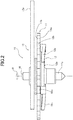
- FIG. 2 is a cross section view illustrating details of the variation reduction mechanism 10.
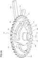
- FIG. 3A is a perspective view illustrating the variation reduction mechanism 10 as seen obliquely downward.
- FIG. 3B is a main cross section view illustrating that a projection 12b contacts a lower surface 11a of a return gear 11 at an angle.
- FIG. 3C is a cross section view corresponding to FIG. 3B and illustrating that the lower surface 11a of the return gear 11 is covered by a hard film 11f.
- FIG. 4 is a perspective view illustrating the variation reduction mechanism 10 as seen obliquely upward
- the illustrated gear train mechanism 80 is a time display mechanism including a rotor 81 of a stepping motor, a fifth wheel 82, a fourth wheel 83, a third wheel 84, a center wheel (second wheel) 85, a minute wheel 86, and an hour wheel 87.
- the rotor 81 of the stepping motor includes a rotor core 81c of a shaft center of the rotor 81, a permanent magnet 81b, and a rotor pinion 81a.
- the permanent magnet 81b and the rotor pinion 81a are fixed to the rotor core 81c to rotate integrally with the rotor core 81c.
- the fifth wheel 82 includes a gear 82a, a pinion 82b having teeth whose number is smaller than that of the gear 82a, and a stem 82c by which the gear 82a and the pinion 82b are coaxially fixed.
- the gear 82a of the fifth wheel 82 engages with a rotor pinion 81a.
- the fourth wheel 83 includes a gear 83a, a pinion 83b having teeth whose number is smaller than that of the gear 83a, and a shaft 83c by which the gear 83a and the pinion 83b are coaxially fixed.
- the gear 83a of the fourth wheel 83 engages with the pinion 82b of the fifth wheel 82.
- the second hand 96 of the timepiece is fixed to the shaft 83c of the fourth wheel 83.
- the third wheel 84 includes a gear 84a, a pinion 84b having teeth whose number is smaller than that of the gear 84a, and a stem 84c by which the gear 84a and the pinion 84b are coaxially fixed.
- the gear 84a of the third wheel 84 engages with the pinion 83b of the fourth wheel 83.
- the center wheel 85 includes a gear 85a, a pinion 85b having teeth whose number is smaller than that of the gear 85a, and a shaft 85c by which the gear 85a and the pinion 85b are coaxially fixed.
- the gear 85a of the center wheel 85 engages with the pinion 84b of the third wheel 84.
- the minute hand 97 of the timepiece is fixed to the shaft 85c.
- the shaft 85c is formed into a hollow cylinder.
- the shaft 83c of the fourth wheel 83 is separated from the shaft 85c of the center wheel 85 for clearly illustrating a transfer path of a driving force (torque) from the rotor 81.
- the shaft 83c of the fourth wheel 83 is coaxially disposed in a hollow space of the shaft 85c to be coaxial therewith.
- the minute wheel 86 includes a gear 86a, a pinion 86b having teeth whose number is smaller than that of the gear 86a, and a stem 86c by which the gear 86a and the pinion 86b are coaxially fixed.
- the gear 86a of the minute wheel 86 engages with the pinion 85b of the center wheel 85.
- the hour wheel 87 includes a gear 87a and a shaft 87c to which the gear 87a is fixed.
- the gear 87a of the hour wheel 87 engages with the pinion 86b of the minute wheel 86.
- the hour hand 98 of the timepiece is fixed to the shaft 87c.
- the shaft 87c is formed into a hollow cylinder.
- the shaft 87c of the hour wheel 87 is separated from the shaft 85c of the center wheel 85 for clearly illustrating a transfer path of a driving force (torque) from the rotor 81.
- the shaft 85c of the center wheel 85 is disposed in the hollow space of the shaft 87c to be coaxial therewith.
- the rotation driving force generated in the rotor 81 is sequentially transferred to the fifth wheel 82, the fourth wheel 83, the third wheel 84, the center wheel 85, the minute wheel 86, and the hour wheel 87 while reducing a speed to rotate the second hand 96, the minute hand 97, and the hour hand 98.
- the respective pointers (second hand 96, minute hand 97, and hour hand 98) indicate, for example, indexes displayed on a dial of the timepiece, the timepiece displays a time.
- the respective pointers rotate in a clockwise direction (normal hand movement direction for displaying time).
- a correction mechanism 90 of forcibly correcting a time (hour and minute) indicated by each of the pointers rotated by the rotor 81 is combined with the gear train mechanism 80.
- the correction mechanism 90 includes a crown 91, a winding stem 92, a clutch wheel 93, and a setting wheel 94.
- the correction mechanism 90 has a known configuration. In the correction mechanism 90, the rotation displacement when the crown 91 rotates about the winding stem 92 by pulling the crown 91 in an axial direction of the winding stem 92 is sequentially transferred to the winding stem 92, the clutch wheel 93, and the setting wheel 94.
- the rotation displacement of the setting wheel 94 is then transferred to the gear 86a of the minute wheel 86 engaging with the setting wheel 94.
- the pinion 85b of the center wheel 85 engaging with the gear 86a of the minute wheel 86 and the gear 87a of the hour wheel 87 engaging with the pinion 86b of the minute wheel 86 rotate to rotate the center wheel 85 and the hour wheel 87.
- the rotation displacement of the center wheel 85 and the hour wheel 87 corresponds to the rotation displacement of the crown 91.
- the minute hand 97 and the hour hand 98 therefore rotate in accordance with the rotation displacement of the crown 91 to correct a minute and an hour to be indicated.
- the center wheel 85 in the gear train mechanism 80 of the present embodiment is configured to allow slip between the gear 85a and the shaft 85c.
- the slip thus occurs between the shaft 85c of the center wheel 85 in which the torque is input from the correction mechanism 90 and the gear 85a of the center wheel 85 in which the torque transferred from the rotor 81 is input, and the minute hand 97 rotates in accordance with the torque input from the correction mechanism 90.
- the rotation transferred from the correction mechanism 90 to the gear train mechanism 80 is not transferred to the third wheel 84, the fourth wheel 83, the fifth wheel 82, and the rotor 81 which are disposed in the upstream of the center wheel 85.
- the variation reduction mechanism 10 of a first embodiment (Embodiment 1) of the present disclosure engages with the pinion 84b of the third wheel 84 which is not affected by the rotation transferred from the correction mechanism 90.
- the variation reduction mechanism 10 of the present embodiment is allowed to rotate in the direction opposite to the normal hand movement direction for displaying a time in the gear train mechanism 80, the variation reduction mechanism 10 may be disposed to engage with the center wheel 85, the minute wheel 86, and the hour wheel 87 which can rotate in the direction opposite to the normal hand movement direction by the torque input from the correction mechanism 90.
- the variation reduction mechanism 10 includes a return gear 11 (one example of return gear), a slip torque spring 12 (one example of friction member), a return spring 13 (one example of return spring member), and a stem 14.
- a hole (not shown) is formed in the center of the return gear 11.
- the return gear 11 rotates about the stem 14 which loosely penetrates through the hole. As the stem 14 loosely contacts the return gear 11, the stem 14 does not rotate integrally with the return gear 11.
- the stem 14 rotatably supports the return gear 11.
- the return gear 11 engages with the pinion 84b of the third wheel 84, and drives in conjunction with the gear train mechanism.
- the slip torque spring 12 is disposed under a lower surface 11a of the return gear 11.
- the slip torque spring 12 is fixed to the stem 14 and rotates integrally with the stem 14.
- the slip torque spring 12 is not fixed to the return gear 11, and is rotatable independently from the return gear 11.
- the slip torque spring 12 includes a plate portion 12a and an arm portion 12c.
- the plate portion 12a is provided in the center portion of the slip torque spring 12. A hole (not shown) is formed in the center of the plate portion 12a. The stem 14 penetrates through the hole to be fixed.
- the arm portion 12c extends from an outer circumferential edge of the plate portion 12a to have a band-like shape.
- Three arm portions 12c are provided at equal angle intervals (120° intervals) around the hole formed in the center of the plate portion 12a.
- at least one arm portion 12c is required; however, a plurality of arm portions 12c improve balance in the circumference direction around the hole.
- the arm portions 12c are provided at equal angle intervals. Such a configuration improves the balance in the circumference direction to be better than a configuration in which the arm portions 12c are provided at unequal angle intervals.
- Each arm portion 12c extends in the circumference direction around the hole of the plate portion 12a. A leading end of each arm portion 12c comes close to a bottom (base end) of another arm portion 12c next to each other. Each arm portion 12c has a length in the circumference direction, which corresponds to about 120° around the hole. The extending direction of the arm portion 12c is identical with the rotation direction of the return gear 11 engaging with the gear train mechanism 80 rotating in the normal hand movement direction for displaying a time.
- Each arm portion 12c is made of an elastically deformable material.
- the leading end of each arm portion is provided with a short cylindrical projection 12b.
- the projection 12b projects from an upper surface (surface facing lower surface 11a of return gear 11) of the arm portion 12c toward the lower surface 11a of the return gear 11.
- Each projection 12b contacts the lower surface 11a of the return gear 11 when the plate portion 12a is fixed to the stem 14.
- the arm portion 12c has a constant rigidity
- the projection 12b projects from the upper surface of the arm portion 12c, as illustrated in FIG. 2
- the arm portion 12c elastically deforms to bend downward within the elastic deformation region of the arm portion 12c.
- a restoring force (elastic force) by the elastic deformation of the arm portion 12c becomes a normal force which presses the projection 12b to the lower surface 11a of the return gear 11.
- the friction force generated in the return gear 11 by the slip torque spring 12 is a load smaller than a load which stops the return gear 11 relative to the torque by the normal hand movement for displaying a time, which is transferred from the pinion 84b of the third wheel 84 with which the return gear 11 engages. Accordingly, while the torque by the normal hand movement for displaying a time is applied to the return gear 11, when the stem 14 and the slip torque spring 12 are prevented from rotating by a torque larger than the torque by the normal hand movement, the friction force by the slip torque spring 12 cannot stop rotating the return gear 11, and slip occurs between the return gear 11 and the slip torque spring 12.
- the timepiece into which the variation reduction mechanism 10 is incorporated includes a mechanism of rotating the rotor 81 in the direction opposite to the normal hand movement direction for displaying a time, namely, when a time is corrected by rotating the rotor 81 in the direction opposite to the normal hand movement direction with a control device of a timepiece as a wave correction timepiece in addition to a manual time correction mechanism with the correction mechanism 90, for example, the torque in the direction opposite to the normal hand movement direction is applied to the return gear 11 from the third wheel 84.
- the projection 12b projects from the upper surface of the arm portion 12c, as illustrated in FIG. 3B , when the arm portion 12c bends downwardly, the projection 12b which contacts the lower surface 11a of the return gear 11 also inclines relative to the lower surface 11a along the bent arm portion 11c. That is to say, when the upper surface of the projection 12b is parallel to the upper surface of the arm portion 12c, the upper surface of the projection 12b provided in the leading end of the arm portion 12b inclines by the bent arm portion 12b at a predetermined angle other than 0° without being parallel to the lower surface 11a of the return gear 11.
- the entire upper surface of the projection 12b does not contact the lower surface 11a of the return gear 11, and a part of the upper surface (corner portion connected to arm portion 12c) of the projection 12b contacts the lower surface 11a of the return gear 11.
- the surface pressure of the projection 12b to the lower surface 11a becomes higher than that when the entire upper surface of the projection 12b contacts the lower surface 11a.
- the lower surface 11a of the return gear 11 may wear or be shaved by the contact of a high surface pressure with the inclined projection 12b.
- the return gear 11 is made of a material having a hardness higher than that of the projection 12b (slip torque spring 12).
- the slip torque spring 12 is a made of a general elastic material (for example, stainless).
- the material having a hardness higher than that includes, for example, carbon steel, nickel (Ni), and phosphorus compound (NiP) in which phosphorus (P) is added to nickel (Ni).
- the high hardness material is not limited to the exampled materials, and any material may be used as long as it has a hardness higher than that of the projection 12b.
- the high hardness material includes a material having a high hardness by a hardening process such as a heat process.
- the return gear 11 may be made of the same material (for example, stainless steel) as the slip torque spring 12, and the return gear 11 is processed by the hardening process, so as to obtain the return gear 11 having a hardness higher than that of the slip torque spring 12.
- the above-described high hardness materials by the own properties for example, carbon steel, nickel (Ni), and phosphorus compound (NiP) in which phosphorus (P) is added to nickel (Ni) may be processed by the hardening process.
- the return gear 11 is made of a material having a hardness higher than that of the projection 12b (slip torque spring 12), the lower surface 11a of the return gear 11 is prevented or controlled from wearing or being shaved.
- the lower surface 11a of the return gear 11 that the projection 12b contacts may be made of the material having a hardness higher than that of the projection 12b. More specifically, as illustrated in FIG. 3C , for example, a hard film 11f having a hardness higher than that of the projection 12b may be provided on the lower surface 11a.
- the hard film 11f includes, for example, a DLC (diamond like carbon) film.
- the hard film 11f is not limited to the exampled DLC film, and may include any film as long as it has a hardness higher than that of the projection 12b.
- a method of providing a hard film is not limited to a specific method such as an applying method and a plating method.
- the lower surface 11a of the return gear 11 is covered by the hard film 11f harder than the projection 12b (slip torque spring 12), the lower surface 11a of the return gear 11 is prevented or controlled from wearing or being shaved.
- the lower surface 11a of the return gear 11 may not wear or may not be shaved. In this case, it is not necessary for the return gear 11 to be made of the high hardness material (including high hardness material by hardening process) or to provide the hard film 11f on the lower surface 11a.
- the return gear it is not always necessary for the return gear to be made of the high hardness material (including high hardness material by hardening process) or to provide the hard film.
- the return gear 11 may be made of the high hardness material (including high hardness material by hardening process) or the hard film may be provided on the lower surface 11a.
- the return spring 13 is disposed above the upper surface 11b of the return gear 11.
- the return spring 13 is fixed to the stem 14, and rotates together with the stem 14. Namely, the return spring 13 and the slip torque spring 12 integrally rotate.
- the return spring 13 is not fixed to the return gear 11, and is rotatable independently from the return gear 11.
- the return spring 13 includes a base portion 13d (one example of fixed member), a stopper portion 13a (one example of regulation member), and a spring portion 13c (one example of spring portion).
- the base portion 13d is a plate provided in the center portion of the return spring 13. A hole (not shown) is formed in the center of the base portion 13d. The stem 14 penetrates through the hole to be fixed. The base portion 13d does not contact the upper surface 11b of the return gear 11.
- the stopper portion 13a is provided in the outer circumference edge of the base portion 13d in the radial direction to project outward from the outer circumference of the return gear 11.
- the stopper portion 13a regulates the rotation range of the return spring 13 within the range of a space 75 provided in a main plate 70 of the after-described movement.
- the spring portion 13c extends in the circumference direction around the stem 14 from a part of the stopper portion 13a located inside the radius of the return gear 11.
- a base end of the spring portion 13c is a fixed end connected to the stopper portion 13a while a leading end of the spring portion 13c is a free end apart from the stopper portion 13a.
- the spring portion 13c is made of an elastically deformable material.
- a restoring force elastic force
- the free end of the spring portion 13c is provided with a hook portion 13b projecting outward in the radial direction from the outer circumference of the return gear 11.
- the hook portion 13b includes a side edge 13e provided on the stretched side of the spring portion 13c.
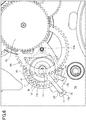
- FIGs. 5 , 6 , 7 are views describing the operation of the variation reduction mechanism 10.
- FIG. 5 illustrates the variation reduction mechanism 10 before being incorporated into the movement, and in which the elastic force is not generated in the spring portion 13c of the return spring 13.
- FIGs. 6 , 7 illustrate the variation reduction mechanism 10 after being incorporated into the movement, and in which the elastic force is generated in the spring portion 13c of the return spring 13.
- the main plate 70 of the movement includes the space 75 in which the stopper portion 13a is disposed, and a space 76 in which the hook portion 13b is disposed.
- the space 75 is provided between walls 71, 72 of the main plate.
- the space 75 has a length in which the stopper portion 13a slightly moves in the circumference direction around the stem 14.
- the space 76 is provided between walls 73, 74 of the main plate.
- the space 76 is provided inside the space 75. However, it is not always necessary to provide the space 76 as long as the wall 74 to which the hook portion 13b is hooked is provided.
- the stopper portion 13a is disposed in the space 75 and the hook portion 13b is disposed in the space 76.
- the spring portion 13c is elastically deformed in the direction in which the fixed end and the free end come close to each other. Namely, the spring portion 13c is elastically deformed in the direction in which the stopper portion 13a and the hook portion 13b come close to each other. That is to say, the spring portion 13c generates the elastic force in the direction in which the stopper portion 13a and the hook portion 13b separate.
- a side edge 13f of the stopper portion 13a which is the stretched side edge of the spring portion 13c, thereby contacts the wall 71 of the main plate, and a side edge 13e of the hook portion 13b, which is the stretched side edge of the spring portion 13c, contacts the wall 74 of the main plate, so that an initial elastic force acts on the return spring 13.
- the fixed end of the spring portion 13c is connected to the stopper portion 13a, the stopper portion 13a is connected to the base portion 13d, and the base portion 13d is connected to the slip torque spring 12 through the stem 14.
- the initial elastic force is thereby applied to the return gear 11 through the projection 12b of the slip torque spring 12.
- the torque in the normal hand movement direction for displaying a time is transferred from the pinion 84b of the third wheel 84 to the return gear 11, and the rotation direction by the torque corresponds to an arrow R direction (counterclockwise direction in FIG. 6 ).
- the direction of the torque by the elastic force received from the slip torque spring 12 corresponds to the direction (clockwise direction in FIG. 6 ) opposite to the arrow R direction.
- the teeth of the return gear 11 apply the torque in the direction opposite to the normal hand movement direction for displaying a time to the pinion 84b of the third wheel 84.
- the torque in the direction opposite to the normal hand movement direction for displaying a time is applied to the fourth wheel 83 and the fifth wheel 82 in the upstream of the third wheel 84 in the driving force transferring direction.
- the teeth of the third wheel 84, the fourth wheel 83, and the fifth wheel 82 are thereby pressed against each other on one side of the backlash.
- the fluctuation caused by the backlash and the variations in the stop position of the second hand 96 fixed to the fourth wheel 83 are thereby prevented or controlled.
- the return spring 13 As the return spring 13 is connected to the slip torque spring 12 through the stem 14, the return spring 13 rotates in the arrow R direction as illustrated in FIG. 7 together with the slip torque spring 12. At this time, the base portion 13d and the stopper portion 13a of the return spring 13 rotate together with the slip torque spring 12 while the hook portion 13b does not rotate because the front side edge 13e of the hook portion 13b in the rotation direction (arrow R direction) contacts the wall 74 of the main plate 70. As a result, the elastic deformation of the spring portion 13c increases in accordance with the increase in the rotation of the slip torque spring 12.
- the return gear 11 rotates in the arrow R direction by the hand movement operation, and the slip torque spring 12 slips.
- the rotation torque in a dashed line arrow - R direction is applied to the stem 14 by the reaction force from the return spring 13.
- the rotation torque in the dashed line arrow - R direction is also transferred to the return gear 11 through the slip torque spring 12 integrated with the stem 14, and the rotation torque (load torque) in the direction opposite to the normal hand movement direction is transferred to the wheels (fourth wheel 83, fifth wheel 82, and rotor 81) before the third wheel 84 engaging with the return gear 11.
- the amount of backlash is thereby reduced between the respective wheels (fourth wheel 83, fifth wheel 82 and the rotor 81) before the third wheel 84, and the fluctuation of the second hand 96 is controlled, and the variations in the stop position of the second hand 96 fixed to the fourth wheel 83 are reduced (prevented or controlled).
- the slip occurs between the projection 12b of the slip torque spring 12 and the lower surface 11a of the return gear 11, and only the return gear 11 keeps rotating, and the slip torque spring 12, the stem 14, and the return spring 13 merely receive the friction force from the return gear 11 through the projection 12b, and are not damaged.
- the variation reduction mechanism 10 of the stop position of the second hand 96 of the present embodiment even though the torque in the direction opposite to the normal hand movement direction for displaying a time is applied, the damage can be prevented, and in the rotation in the normal hand movement direction, the teeth of the gears are pressed against each other in the end portion within the backlash in the direction opposite to the normal hand movement direction, so that the variations in the stop position of the second hand 96 can be prevented or controlled to be reduced.
- the stopper portion 13a contacts the wall 72 of the space 75.
- the elastic deformation of the spring portion 13c is thereby regulated within the constant range.
- the stopper portion 13a also contacts the wall 72 of the space 75 before the torque in the direction opposite to the normal hand movement direction, which is generated in the return spring 13 by the elastic force according to the elastic deformation, exceeds the torque by the friction force between the return gear 11 and the return spring 13 (friction force generated between return gear 11 and slip torque spring 12).
- the torque by the elastic force does not exceed the torque by the friction force between the return gear 11 and the return spring 13, and the torque by the constant elastic force according to the elastic deformation of the spring portion 13c when the stopper portion 13a contacts the wall 72 keeps acting on the return gear 11.
- the return spring 13 keeps rotating until the torque by the elastic force of the spring portion 13c exceeds the torque by the friction force between the return gear 111 and the return wheel plate 115. At the exceeding, the return spring 13 drastically slips to the return gear 11, and the torque in the opposite direction, which acts on the return gear 111 may largely change.
- the stopper portion 13a contacts the wall 72 before the torque by the elastic force exceeds the torque by the friction force between the return gear 11 and the slip torque spring 12.
- the constant torque in the opposite direction, which acts on the return gear 11, can be maintained.
- a part of the slip torque spring 12 which contacts the return gear 11 is the projection 12b pressed to the return gear 11 by the elastic force of the arm portion 12c.
- the friction force by the return gear 11 can be easily changed by changing the height of the projection.
- the area which contacts the return gear 11 can be also changed by changing the area of the projection 12b.
- the return spring 13 and the slip torque spring 12 are integrated through the stem 14.
- the workability of incorporating the variation reduction mechanism 10 into the movement is better than that in which the return spring 13 and the slip torque spring 12 are not integrated.
- FIG. 8 is a view illustrating the variation reduction mechanism 10 of Modified Example in which the slip torque spring 12 is disposed between the return gear 11 and the return spring 13.
- FIG. 9 is a view describing the operation of the variation reduction mechanism 10 illustrated in FIG. 8 .
- the variation reduction mechanism 10 of the stop position of the second hand 96 of Embodiment 1 is configured that the slip torque spring 12 and the return spring 13 are disposed in difference sides of the return gear 11, respectively.
- a plate spring may be applied as the slip torque spring 12, and this slip torque spring 12 may be disposed between the return gear 11 and the return spring 13.
- both of the slip torque spring 12 and the return spring 13 are disposed above the upper surface 11b of the return gear 11.
- the slip torque spring 12 illustrated in FIG. 8 is, for example, a disc shaped elastic member. A hole is formed in the center portion of the slip torque spring 12. The stem 14 loosely penetrates through the hole. A part of the slip torque spring is bent upward in the thickness direction. The slip torque spring 12 is sandwiched by the return gear 11 and the base portion 13d of the return spring 13, so that the upwardly bent part of the slip torque spring 12 is elastically deformed to be unbent.
- the elastic force is generated in the bent part of the slip torque spring 12, and the normal force by the elastic force is generated between the return gear 11 and the base portion 13d of the return spring 13.
- a friction force similar to the friction force generated between the return gear 11 and the slip torque spring 12 in Embodiment 1 is thereby generated between the return gear 11 and the return spring 13.
- slip torque spring 12 When the slip torque spring 12 is not fixed to the return gear 11, the return spring 13 and the stem 14, or the slip torque spring 12 is fixed to the return gear 11 or the return spring 13 and the stem 14, the slip can be generated between the return gear 11 and the return spring 13.
- the variation reduction mechanism 10 illustrated in FIG. 8 does not include the stopper portion 13a, but may include the stopper portion 13a. As described in Embodiment 1, the variation reduction mechanism 10 including the stopper portion 13a controls a change in a magnitude of the friction force which is applied to the rotating return gear 11 to be better than the variation reduction mechanism 10 without the stopper portion 13a.
- the friction force in the direction opposite to the normal hand movement direction for displaying a time is not applied to the return gear 11 in the initial stage.
- the spring portion 13c elastically deforms in accordance with the increase in the rotation of the return gear 11, and the friction force in the direction (dashed line arrow - R direction) opposite to the arrow R direction is applied to the return gear 11 from the base end portion of the return spring 13 through the slip torque spring 12.
- the torque in the direction opposite to the normal hand movement direction for displaying a time is thereby applied to the return gear 11, and the variations in the stop position of the second hand 96 can be thus reduced.
- the friction member (slip torque spring 12 in Embodiment 1 and Modified Example) in the variation reduction mechanism according to the present disclosure is not limited to the configuration of the above-described slip torque spring 12. Any configuration can be applied as long as it applies the friction force to the driving of the return gear by the contact to the return gear, and generates the slips between the return gear and the spring member when a constant torque or more is applied.
- FIG. 10 is an exploded perspective view illustrating a return gear 111, a slip torque spring 112, a return wheel plate 115, and a stem 114 as components of a variation reduction mechanism 110 of a stop position of a pointer (second hand 96 as one example) of a second embodiment (Embodiment 2) according to the present disclosure.
- FIG. 11 is a perspective view illustrating a plate spring 116 as a component of the variation reduction mechanism 110.
- FIG. 12 is a cross section view of an assembly of the return gear 111, the slip torque spring 112, the return wheel plate 115, and the stem 114 in FIG. 10 .
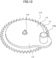
- FIG. 13 is a perspective view of the assembly of the return gear 111, the slip torque spring 112, the return wheel plate 115, and the stem 114.
- the variation reduction mechanism 110 of the second embodiment (Embodiment 2) includes the return gear 111 (one example of return gear), the slip torque spring 112 (one example of friction member), the stem 114, and the return spring member 113 (one example of return spring member).
- the return spring member 113 includes the return wheel plate 115 (one example of fixed member of return spring member) and the plate spring 116 (one example of spring member of return spring member).
- the return gear 111 of the variation reduction mechanism 110 corresponds to the return gear 11
- the slip torque spring 112 corresponds to the slip torque spring 12
- the stem 114 corresponds to the stem 14
- the return spring member 113 corresponds to the return spring 13 in the variation reduction mechanism 10 of Embodiment 1.
- the return wheel plate 115 corresponds to the base portion 13d of the return spring 13
- the plate spring 116 corresponds to the spring portion 13c.
- the variation reduction mechanism 110 engages with the pinion 84b of the third wheel 84 to reduce the variations in the second hand 96.
- the variation reduction mechanism 110 includes the return gear 111, the slip torque spring 112, the return wheel plate 115, the stem 114, and the plate spring 116.
- the return gear 111, the slip torque spring 112, the return wheel plate 115, and the stem 114 are assembled to be integrated as illustrated in FIGs. 12 , 13 .
- the plate spring 116 is incorporated into the main plate 70 in the movement of the timepiece into which the variation reduction mechanism 110 is incorporated.
- the return gear 111 engages with the pinion 84b of the third wheel 84, similar to the return gear 11.
- a hole 111c is formed in the center of the return gear 111.
- the stem 114 is inserted into the hole 111c from a lower surface 11a. The stem 114 loosely penetrates through the hole 111c.
- the return gear 111 is thereby independently rotatable relative to the stem 114.
- the stem 114 includes a retainer 114a having a diameter larger than that of the hole 111c of the return gear 111.
- the retainer 114a contacts the lower surface 111a of the return gear 111.
- the slip torque spring 112 is a disc shaped elastic member, and is made of a material. A part of the slip torque spring 112 is bent upward in the thickness direction. This slip torque spring 112 is the same as the slip torque spring 12 illustrated in FIGs. 8 , 9 . A hole 112c is formed in the center of the slip torque spring 112.
- the slip torque spring 112 is disposed above an upper surface 111b of the return gear 111 to overlap with the return gear 111.
- the stem 114 is inserted into the hole 112c of the slip torque spring 112 from the lower surface.
- the stem 114 loosely penetrates through the hole 112c.
- the slip torque spring 112 is thereby independently rotatable relative to the stem 114.
- a hole 115c is formed in the center of the return wheel plate 115.
- the return wheel plate 115 is disposed above the upper surface 111b of the return gear 11 to overlap with the slip torque spring 112.
- the return wheel plate 115 and the return gear 111 sandwich therebetween the slip torque spring 112.
- the return wheel plate 115 includes a short cylindrical return wheel pin 115d (one example of regulation member) which projects upward opposite to a lower surface 115a that the slip torque spring 112 contacts.
- the stem 114 is inserted into the hole 115c of the return wheel plate 115 from the lower surface 115a.
- the stem 114 is fitted into the hole 115c, and the return wheel plate 115 is fixed to the stem 114.
- the return wheel plate 115 is fixed to the stem 114 such that the bent portions 112a, 112b of the slip torque spring 112 are elastically deformed to be unbent as illustrated in FIG. 12 .
- the elastic force is generated in the deformed portion of the slip torque spring 112, the normal force by the elastic force is generated between the return gear 111 and the return wheel plate 115, and the friction force described in Embodiment 1 is also generated between the return gear 11 and the return wheel plate 115.
- FIG. 14 is a view describing the operation of the variation reduction mechanism 10 of Embodiment 2, and illustrating that the variation reduction mechanism 110 is incorporated into the movement, and the return wheel pin 115d contacts the plate spring 116 of the return spring member 113.
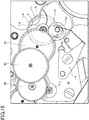
- FIG. 15 is a view describing the operation of the variation reduction mechanism 10, and illustrating that the variation reduction mechanism 10 is incorporated into the movement, and the torque by the elastic force of the plate spring 116 acts on the return wheel pin 115d.
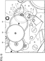
- FIG. 16 is a view describing the operation of the variation reduction mechanism 110, and illustrating that the variation reduction mechanism 110 is incorporated into the movement, and the gear train mechanism 80 rotates in the direction opposite to the normal hand movement direction.
- the plate spring 116 includes a plate fixed portion 116a and a spring portion 116b elongating like an arm from the fixed portion 116a.
- the fixed portion 116a is fixed to the main plate 70 of the movement of the timepiece by a screw 78, for example.
- the variation reduction mechanism 110 is incorporated into the movement of the timepiece.
- the spring portion 116b is made of an elastic deformable material. A base end of the spring portion 116b is connected to the fixed portion 116a, and a free end of the spring portion 116b contacts an outer circumference surface of the return wheel pin 115d of the variation reduction mechanism 110 incorporated in to the movement. In the figure, the free end of the spring portion 116b contacts the return wheel pin 115d from the right side of the figure.
- the return wheel plate 115 and the plate spring 116 constitute the return spring member 113.
- the return spring member 113 operates similar to the return spring 13 in Embodiment 1.
- FIGs. 15 , 16 are views describing the operation of the variation reduction mechanism 110.
- FIG. 15 is a view illustrating that the variation reduction mechanism 110 is incorporated into the movement, and the torque by the elastic force acts on the return wheel pin 115d.
- FIG. 16 is a view illustrating that the variation reduction mechanism 110 is incorporated into the movement, and the gear train mechanism 80 rotates in the direction opposite to the normal hand movement direction.
- the torque in the normal hand movement direction for displaying a time is transferred from the third wheel 84 to the return gear 111.
- the rotation direction by the torque is the arrow R direction (counterclockwise direction in FIG. 14 ).
- the return wheel plate 115 of the return spring member 113 starts rotating in the arrow R direction together with the slip torque spring 112 by the friction force due to the normal force acting between the return wheel plate 115 and the slip torque spring 112.
- the return wheel pin 115d is displaced in the right direction by the rotation of the return wheel plate 115 as illustrated in FIG. 15 , and the spring portion 116b of the plate spring 116 starts being elastically deformed.
- the elastic force of the spring portion 116b is applied to the return wheel pin 115d, and the torque in the direction (dashed line arrow - R direction) opposite to the normal hand movement direction (arrow R direction) is applied to the return wheel plate 115.
- the return wheel plate 115 contacts the slip torque spring 112 by the friction force, and the slip torque spring 112 contacts the return gear 111 by the friction force. Thus, the torque applied to the return wheel plate 115 is applied to the return gear 111.
- the return gear 11 applies the torque in the direction opposite to the normal hand movement direction for displaying a time to the third wheel 84 with which the teeth of the return gear 11 engage.
- the torque in the direction opposite to the normal hand movement direction for displaying a time is therefore applied to the fourth wheel 83 and the fifth wheel 82 in the upstream of the third wheel 84 in the driving force transferring direction.
- the teeth of the third wheel 84, the fourth wheel 83, and the fifth wheel 82 are pressed against each other in the one side of the backlash.
- the variations in the stop position of the second hand 96 fixed to the fourth wheel 83 caused by the backlash is prevented or controlled in the normal hand movement operation for displaying a time.
- the return gear 111 rotates in the arrow R direction by the hand movement operation. After the slip occurs between the return wheel plate 115 and the slip torque spring 112 and/or between the slip torque spring 112 and the return gear 111, the rotation torque in the dashed line arrow - R direction is applied to the return wheel plate 115 by the reaction force from the spring portion 116b.
- the rotation torque applied to the return wheel plate 115 is transferred to the return gear 11 through the slip torque spring 112, and the rotation torque (load torque) in the direction opposite to the normal hand movement direction is transferred to the wheels (fourth wheel 83, fifth wheel 82, and rotor 81) before the third wheel 84 engaging with the return gear 111.
- the amount of the backlash between the respective wheels (fourth wheel 83, fifth wheel 82, and rotor 81) before the third wheel 84 is thereby reduced, so that the fluctuation of the second hand 96 is controlled, and the variations in the stop position of the second hand 96 fixed to the fourth wheel 83 are reduced (prevented or controlled).
- the slip occurs between the return wheel plate 115 and the slip torque spring 112 or between the slip torque spring 112 and the return gear 111. Accordingly, only the return gear 111 or both of the return gear 111 and the slip torque spring 112 keeps/keep rotating, and the return spring member 113 including the return wheel plate 115 and the plate spring 116 merely receives the friction force from the slip torque spring 112 and is not damaged.
- the teeth of the gears are always pressed against each other in the end portion within the backlash in the direction opposite to the normal hand movement direction in the rotation in the normal hand movement direction, so that the fluctuation of the second hand 96 and the variations in the stop position of the second hand 96 can be prevented and controlled to be reduced without damage when the torque in the direction opposite to the normal hand movement direction for displaying a time is applied.
- the return spring member 113 is divided into the plate spring 116 and the return wheel plate 115 fixed to the stem 114.
- the plate spring 116 can be thereby disposed in the movement, and the freedom degree of disposing the variation reduction mechanism 110 can be improved.
- FIGs. 17 , 18 are views illustrating the variation reduction mechanism 110 of Modified Example 1 in which the rotation range of the return wheel plate 115 is smaller than that of the variation reduction mechanism 110 of Embodiment 2 illustrated in FIGs. 14 to 16 .
- FIG. 17 is a view illustrating that the return wheel pin 115d contacts the wall 72 (forward wall in hand movement direction) of the main plate 70 during the operation in the normal hand movement direction.
- FIG. 18 is a view illustrating that the return wheel pin 115d contacts the opposite wall 71 (backward wall in hand movement direction) of the main plate 70 during the operation in the direction opposite to the normal hand movement direction.
- a window (space) 75 from which the return wheel pin 115d projects is downsized.
- the window 75 is provided in the main plate 70 in the movement of the timepiece into which the variation reduction mechanism 110 is incorporated.
- the diameter of the return wheel pin 115d may be increased. Namely, the diameter of the return wheel pin 115d relative to the diameter of the window 75 may be increased.
- the elastic deformation of the spring portion 116b is regulated within the rotation range of the return wheel pin 115d.
- the return wheel pin 115d contacts the wall 72 of the window 75 before the torque in the direction opposite to the normal hand movement direction, which is generated in the return wheel plate 115 by the elastic force according to the elastic deformation, exceeds the torque by the friction force between the return gear 111 and the return wheel plate 115 (smaller friction force between friction force generated between return gear 111 and slip torque spring 112 and friction force generated between slip torque spring 112 and return wheel plate 115).
- the torque by the elastic force does not exceed the torque by the friction force between the return gear 111 and the return wheel plate 115, and the torque by the constant elastic force according to the elastic deformation of the spring portion 116b when the return wheel pin 115d contacts the wall 72 of the window 75 keep acting on the return gear 111.
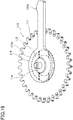
- FIG. 19 is a perspective view illustrating a return wheel plate 215 including a return wheel lever 215d which is provided instead of the return wheel plate 115 in the variation reduction mechanism 110 of Embodiment 2.
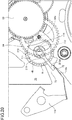
- FIG. 20 is a view describing the operation of the variation reduction mechanism 210 of the stop position of the pointer (second hand 96 as one example) in Modified Example 2 including the return wheel plate 215.
- the variation reduction mechanisms 110 of Embodiment 2 and Modified Example 1 are configured that the return wheel pin 115d is provided in the return wheel plate 115.
- the spring portion 116b may be elastically deformed by another regulation member instead of the return wheel pin 115d.
- the return wheel plate 215 illustrated in FIG. 19 may be used instead of the return wheel plate 115 of the variation reduction mechanism 110.
- a plate main portion 215a contacting the slip torque spring 112 is formed to be smaller than the return wheel plate 115 illustrated in FIG. 10 , and the return wheel lever 215d (one example of regulation member) extends outward the outer circumference edge of the return gear 111 in the radial direction from the main portion.
- the return wheel pin 115d of the return wheel plate 115 illustrated in FIG. 10 projects in the thickness direction of the return wheel plate 115, and the return wheel pin 115d contacts the spring portion 116b in the projected region in the thickness direction.
- the occupied space in the plane of the return wheel plate 115 can be thereby reduced.
- the return wheel lever 215d of the return wheel plate 215 projects outward in the radial direction from the side surface of the return wheel plate 215, and contacts the spring portion 116b in the projected region in the radial direction.
- the return wheel lever 215d is provided, the occupied space of the return wheel plate 115 in the thickness direction can be reduced.
- the return gear 111 rotates in the normal hand movement direction (arrow R direction) for displaying a time, and the return wheel lever 215d rotates in the arrow R direction along the rotation of the return gear 111 while pressing the spring portion 116b.
- the relationship between the position of the return wheel lever 215d and the size of the space 75 of the main plate 70 is set such that the spring portion 116b is elastically deformed by being pressed by the return wheel lever 215d before the torque in the opposite direction by the elastic force of the spring portion 116b exceeds the torque by the friction force between the return gear 111 and the return wheel plate 215, so that the constant torque in the opposite direction, which is applied to the return gear 111, can be maintained.
- the variation reduction mechanism 10 is not limited to reduce the variations in the stop position of the second hand only.
- the target of reducing the variations in the stop position may be a minute hand or an hour hand, for example.
- the variations in the stop position are relatively large in the pointer having a high moving frequency. For this reason, the effects of the variation reduction of the second hand having a high moving frequency are larger than the others.
- the pointer having a high moving frequency includes a pointer for chronograph.
Landscapes
- Physics & Mathematics (AREA)
- General Physics & Mathematics (AREA)
- Engineering & Computer Science (AREA)
- General Engineering & Computer Science (AREA)
- Mechanical Engineering (AREA)
- Electromechanical Clocks (AREA)
- Gears, Cams (AREA)
Abstract
Description
- This disclosure relates to a variation reduction mechanism for reducing variations in a stop position of a pointer.
- A gear train mechanism includes a plurality of gears for rotating pointers of a timepiece. Such a gear train mechanism has backlash for smoothly engaging teeth of the gears to rotate the gears. The engaged teeth thereby have therebetween play (looseness) by the backlash, so that the gears can move within the play.
- As the pointer of the timepiece is fixed to the gear, the pointer of the timepiece moves in accordance with the movement of the gear. When the gear voluntarily moves within the play as described above, the pointer also moves in accordance with the movement of the gear. Accordingly, in a timepiece in which hand movement is visually recognized, such as in a hand second, fluctuation of the pointer becomes noticeable.
- In order to prevent or control such movement of the gears within the play, a plate spring is pressed to an end surface of the gear to generate a friction force between the gear and the plate spring. In this case, the stop position of the gear is determined based on balance between an inertial moment at rotation of a rotor of a stepping motor for driving, for example, a gear train and a load torque generated by the friction force by the plate spring. The fluctuation of the pointer is thereby controlled; however, the stop position of the pointer easily varies.
- Accordingly, a technique is proposed (see, for example, Patent Literature 1). With such a technique, a small torque is applied to gears in a direction opposite to a rotation direction (hand movement direction) for displaying a normal time by using a spiral spring to press the teeth of the gears in the direction opposite to the hand movement direction, so as to reduce the amount of backlash (no play).
- With this technique, the variations in the stop position of the pointer can be reduced while the fluctuation of the pointer is reduced. More specifically, as the teeth of the gears are always pressed against each other in a constant end portion within the play (end portion in direction opposite to hand movement direction), the teeth can be prevented or controlled from playing within the range of the backlash, so that the fluctuation of the pointer can be reduced. Moreover, as the stop position is determined based on the balance between a return torque (load torque in direction opposite to hand movement direction by spiral spring) and a holding torque of the rotor, the variations in the stop position can be reduced.
- Patent Literature 1:
JP2646946B - In a timepiece using the above-described spiral spring, the rotation direction is always set in one direction (hand movement direction). However, when a time is corrected in a timepiece, a pointer is moved in the hand movement direction or in the direction opposite to the hand movement direction. Thus, the pointer is sometimes moved in the direction opposite to the hand movement direction. In the timepiece using the above-described spiral spring, when the torque in the opposite direction is applied to the spiral spring, an unexpected load acts on the spiral spring, so that the spiral spring may be damaged.
- When a time is corrected by a normal crown operation, the gear with which the spiral spring engages does not engage with the gear for correcting a time. When a time is electromagnetically corrected by motor control, it is necessary to rotate the rotor in the direction opposite to the hand movement direction. In this case, as all the gears rotate in the opposite direction, the unexpected load acts on the spiral spring.
- The gears may rotate in the direction opposite to the hand movement direction not only by a time correcting operation but also by various operations corresponding to recent various functions, for example, an operation with an automatic correction function of a pointer position and a return operation from a power saving function.
- The present disclosure has been made in view of the above circumstances, and an object of the present disclosure is to provide a variation reduction mechanism of a stop position of a pointer by which teeth of gears are always pressed against each other in a constant end portion (end portion in direction opposite to hand movement direction) within play when rotating in the normal hand movement direction while preventing a spring from being damaged even when the hand movement is carried out in the direction opposite to the hand movement direction.
- The present disclosure relates to a variation reduction mechanism of a stop position of a pointer. The variation reduction mechanism includes a return gear that is driven in conjunction with a time display mechanism, a friction member that contacts the return gear to apply a friction force to the return gear to be driven, and a return spring member that applies, to the friction member, a torque of the return gear in a direction opposite to a normal hand movement direction for displaying a time.
- With the variation reduction mechanism of the stop position of the pointer according to the present disclosure, the teeth of the gears can be always pressed against each other in the constant end portion (end portion in direction opposite to hand movement direction) within the play in the rotation in the normal hand movement direction while preventing the spring from being damaged even when the hand movement is carried out in the direction opposite to the hand movement direction.
-
- [
FIG. 1] FIG. 1 is a cross section view schematically and functionally illustrating a gear train mechanism for rotating respective pointers (hour hand, minute hand, and second hand) of a timepiece in which a variation reduction mechanism of a stop position of a pointer (second hand as one example) of each embodiment (Embodiments 1, 2 and Modified Examples) of the present disclosure is incorporated. - [
FIG. 2] FIG. 2 is a cross section view illustrating details of the variation reduction mechanism of the stop position of the pointer. - [
FIG. 3A] FIG. 3A is a perspective view of the variation reduction mechanism of the stop position of the pointer as seen obliquely downward. - [
FIG. 3B] FIG. 3B is a main cross section view illustrating that a projection contacts a lower surface of a return gear at an angle. - [
FIG. 3C] FIG. 3C is a cross section view corresponding toFIG. 3B , and illustrating that the lower surface of the return gear is covered by a hard film. - [
FIG. 4] FIG. 4 is a perspective view illustrating the variation reduction mechanism of the stop position of the pointer as seen obliquely upward. - [
FIG. 5] FIG. 5 is a view describing an operation of the variation reduction mechanism of the stop position of the pointer, and illustrating the mechanism before being incorporated into a movement and an elastic force is not generated in a spring portion of a return spring. - [
FIG. 6] FIG. 6 is a view (part 1) describing an operation of the variation reduction mechanism, and illustrating that the mechanism is incorporated into the movement and the elastic force is generated in the spring portion of the return spring. - [
FIG. 7] FIG. 7 is a view (part 2) describing the operation of the variation reduction mechanism, and illustrating that the mechanism is incorporated into the movement and the elastic force is generated in the spring portion of the return spring. - [
FIG. 8] FIG. 8 is a view illustrating a variation reduction mechanism of a modified example in which a slip torque spring is disposed between a return gear and a return spring. - [
FIG. 9] FIG. 9 is a view describing an operation of the variation reduction mechanism illustrated inFIG. 8 . - [
FIG. 10] FIG. 10 is an exploded perspective view illustrating a return gear, a slip torque spring, a return wheel plate, and a stem which are components of a variation reduction mechanism of a stop position of a pointer as a second embodiment (Embodiment 2) of the present disclosure. - [
FIG. 11] FIG. 11 is a perspective view illustrating a plate spring of the variation reduction mechanism. - [
FIG. 12] FIG. 12 is a cross section view of an assembly of the return gear, the slip torque spring, the return wheel plate, and the stem inFIG. 10 . - [
FIG. 13] FIG. 13 is a perspective view of the assembly of the return gear, the slip torque spring, the return wheel plate, and the stem. - [
FIG. 14] FIG. 14 is a view describing an operation of the variation reduction mechanism of the stop position of the pointer of Embodiment 2, and illustrating that the variation reduction mechanism is incorporated into the movement and a return wheel pin contacts the plate spring of a return spring mechanism. - [
FIG. 15] FIG. 15 is a view describing the operation of the variation reduction mechanism, and illustrating that the variation reduction mechanism is incorporated into the movement and a torque by an elastic force of the spring portion acts on the return wheel pin. - [
FIG. 16] FIG. 16 is a view describing the operation of the variation reduction mechanism, and illustrating that the variation reduction mechanism is incorporated into the movement and the gear train mechanism rotates in the direction opposite to the normal hand movement direction. - [
FIG. 17] FIG. 17 is a view illustrating a modified example in which a rotation range of a return wheel plate is reduced to be smaller than that in the mechanism of Embodiment 2 illustrated inFIGs. 14 to 16 , and the return wheel pin contacts a wall of a main plate (forward wall in hand movement direction) during the operation in the normal hand movement direction. - [
FIG. 18] FIG. 18 is a view illustrating the modified example in which the rotation range of the return wheel plate is reduced to be smaller than that in the mechanism of Embodiment 2 illustrated inFIGs. 14 to 16 , and the return wheel pin contacts an opposite wall of the main plate (backward wall in hand movement direction) during the operation in the direction opposite to the normal hand movement direction. - [
FIG. 19] FIG. 19 is a perspective view illustrating a return wheel plate including a return wheel lever which is provided instated of the return wheel plate in the variation reduction mechanism of Embodiment 2. - [
FIG. 20] FIG. 20 is a view illustrating the operation of the variation reduction mechanism of Modified Example 2 including the retune wheel plate. - Hereinafter, embodiments of a variation reduction mechanism of a stop position of a pointer according to the present disclosure will be described with reference to the drawings.
-
FIG. 1 is a cross section view schematically and functionally illustrating agear train mechanism 80 for rotating respective pointers (hour hand 98,minute hand 97, and second hand 96) of a timepiece into which avariation reduction mechanism 10 of a stop position of a pointer (second hand 96 as one example) of respective embodiments (Embodiments 1, 2 and Modified Examples) of the present disclosure is incorporated.FIG. 2 is a cross section view illustrating details of thevariation reduction mechanism 10.FIG. 3A is a perspective view illustrating thevariation reduction mechanism 10 as seen obliquely downward.FIG. 3B is a main cross section view illustrating that aprojection 12b contacts alower surface 11a of areturn gear 11 at an angle.FIG. 3C is a cross section view corresponding toFIG. 3B and illustrating that thelower surface 11a of thereturn gear 11 is covered by ahard film 11f.FIG. 4 is a perspective view illustrating thevariation reduction mechanism 10 as seen obliquely upward. - The illustrated
gear train mechanism 80 is a time display mechanism including arotor 81 of a stepping motor, afifth wheel 82, afourth wheel 83, athird wheel 84, a center wheel (second wheel) 85, aminute wheel 86, and anhour wheel 87. - The
rotor 81 of the stepping motor includes arotor core 81c of a shaft center of therotor 81, apermanent magnet 81b, and arotor pinion 81a. Thepermanent magnet 81b and therotor pinion 81a are fixed to therotor core 81c to rotate integrally with therotor core 81c. - The
fifth wheel 82 includes agear 82a, apinion 82b having teeth whose number is smaller than that of thegear 82a, and astem 82c by which thegear 82a and thepinion 82b are coaxially fixed. Thegear 82a of thefifth wheel 82 engages with arotor pinion 81a. - The
fourth wheel 83 includes agear 83a, apinion 83b having teeth whose number is smaller than that of thegear 83a, and ashaft 83c by which thegear 83a and thepinion 83b are coaxially fixed. Thegear 83a of thefourth wheel 83 engages with thepinion 82b of thefifth wheel 82. Thesecond hand 96 of the timepiece is fixed to theshaft 83c of thefourth wheel 83. - The
third wheel 84 includes agear 84a, apinion 84b having teeth whose number is smaller than that of thegear 84a, and astem 84c by which thegear 84a and thepinion 84b are coaxially fixed. Thegear 84a of thethird wheel 84 engages with thepinion 83b of thefourth wheel 83. - The
center wheel 85 includes agear 85a, apinion 85b having teeth whose number is smaller than that of thegear 85a, and ashaft 85c by which thegear 85a and thepinion 85b are coaxially fixed. Thegear 85a of thecenter wheel 85 engages with thepinion 84b of thethird wheel 84. Theminute hand 97 of the timepiece is fixed to theshaft 85c. - The
shaft 85c is formed into a hollow cylinder. InFIG. 1 , theshaft 83c of thefourth wheel 83 is separated from theshaft 85c of thecenter wheel 85 for clearly illustrating a transfer path of a driving force (torque) from therotor 81. In an actual configuration, theshaft 83c of thefourth wheel 83 is coaxially disposed in a hollow space of theshaft 85c to be coaxial therewith. - The
minute wheel 86 includes agear 86a, apinion 86b having teeth whose number is smaller than that of thegear 86a, and astem 86c by which thegear 86a and thepinion 86b are coaxially fixed. Thegear 86a of theminute wheel 86 engages with thepinion 85b of thecenter wheel 85. - The
hour wheel 87 includes agear 87a and ashaft 87c to which thegear 87a is fixed. Thegear 87a of thehour wheel 87 engages with thepinion 86b of theminute wheel 86. Thehour hand 98 of the timepiece is fixed to theshaft 87c. - The
shaft 87c is formed into a hollow cylinder. InFIG. 1 , theshaft 87c of thehour wheel 87 is separated from theshaft 85c of thecenter wheel 85 for clearly illustrating a transfer path of a driving force (torque) from therotor 81. In an actual configuration, theshaft 85c of thecenter wheel 85 is disposed in the hollow space of theshaft 87c to be coaxial therewith. - In the
gear train mechanism 80 configured as described above, the rotation driving force generated in therotor 81 is sequentially transferred to thefifth wheel 82, thefourth wheel 83, thethird wheel 84, thecenter wheel 85, theminute wheel 86, and thehour wheel 87 while reducing a speed to rotate thesecond hand 96, theminute hand 97, and thehour hand 98. When the respective pointers (second hand 96,minute hand 97, and hour hand 98) indicate, for example, indexes displayed on a dial of the timepiece, the timepiece displays a time. The respective pointers rotate in a clockwise direction (normal hand movement direction for displaying time). - A
correction mechanism 90 of forcibly correcting a time (hour and minute) indicated by each of the pointers rotated by therotor 81 is combined with thegear train mechanism 80. Thecorrection mechanism 90 includes acrown 91, a windingstem 92, aclutch wheel 93, and asetting wheel 94. Thecorrection mechanism 90 has a known configuration. In thecorrection mechanism 90, the rotation displacement when thecrown 91 rotates about the windingstem 92 by pulling thecrown 91 in an axial direction of the windingstem 92 is sequentially transferred to the windingstem 92, theclutch wheel 93, and thesetting wheel 94. - The rotation displacement of the
setting wheel 94 is then transferred to thegear 86a of theminute wheel 86 engaging with thesetting wheel 94. Thepinion 85b of thecenter wheel 85 engaging with thegear 86a of theminute wheel 86 and thegear 87a of thehour wheel 87 engaging with thepinion 86b of theminute wheel 86 rotate to rotate thecenter wheel 85 and thehour wheel 87. The rotation displacement of thecenter wheel 85 and thehour wheel 87 corresponds to the rotation displacement of thecrown 91. Theminute hand 97 and thehour hand 98 therefore rotate in accordance with the rotation displacement of thecrown 91 to correct a minute and an hour to be indicated. - The
center wheel 85 in thegear train mechanism 80 of the present embodiment is configured to allow slip between thegear 85a and theshaft 85c. The slip thus occurs between theshaft 85c of thecenter wheel 85 in which the torque is input from thecorrection mechanism 90 and thegear 85a of thecenter wheel 85 in which the torque transferred from therotor 81 is input, and theminute hand 97 rotates in accordance with the torque input from thecorrection mechanism 90. With the configuration that allows the slip of thecenter wheel 85, the rotation transferred from thecorrection mechanism 90 to thegear train mechanism 80 is not transferred to thethird wheel 84, thefourth wheel 83, thefifth wheel 82, and therotor 81 which are disposed in the upstream of thecenter wheel 85. - The
variation reduction mechanism 10 of a first embodiment (Embodiment 1) of the present disclosure engages with thepinion 84b of thethird wheel 84 which is not affected by the rotation transferred from thecorrection mechanism 90. As thevariation reduction mechanism 10 of the present embodiment is allowed to rotate in the direction opposite to the normal hand movement direction for displaying a time in thegear train mechanism 80, thevariation reduction mechanism 10 may be disposed to engage with thecenter wheel 85, theminute wheel 86, and thehour wheel 87 which can rotate in the direction opposite to the normal hand movement direction by the torque input from thecorrection mechanism 90. - As illustrated in
FIG. 2 , thevariation reduction mechanism 10 includes a return gear 11 (one example of return gear), a slip torque spring 12 (one example of friction member), a return spring 13 (one example of return spring member), and astem 14. A hole (not shown) is formed in the center of thereturn gear 11. Thereturn gear 11 rotates about thestem 14 which loosely penetrates through the hole. As thestem 14 loosely contacts thereturn gear 11, thestem 14 does not rotate integrally with thereturn gear 11. Thestem 14 rotatably supports thereturn gear 11. Thereturn gear 11 engages with thepinion 84b of thethird wheel 84, and drives in conjunction with the gear train mechanism. - As illustrated in
FIGs. 2 ,3A , theslip torque spring 12 is disposed under alower surface 11a of thereturn gear 11. Theslip torque spring 12 is fixed to thestem 14 and rotates integrally with thestem 14. On the other hand, theslip torque spring 12 is not fixed to thereturn gear 11, and is rotatable independently from thereturn gear 11. Theslip torque spring 12 includes aplate portion 12a and anarm portion 12c. - The
plate portion 12a is provided in the center portion of theslip torque spring 12. A hole (not shown) is formed in the center of theplate portion 12a. Thestem 14 penetrates through the hole to be fixed. - The
arm portion 12c extends from an outer circumferential edge of theplate portion 12a to have a band-like shape. Threearm portions 12c are provided at equal angle intervals (120° intervals) around the hole formed in the center of theplate portion 12a. In fact, at least onearm portion 12c is required; however, a plurality ofarm portions 12c improve balance in the circumference direction around the hole. When a plurality ofarm portions 12c are provided, thearm portions 12c are provided at equal angle intervals. Such a configuration improves the balance in the circumference direction to be better than a configuration in which thearm portions 12c are provided at unequal angle intervals. - Each
arm portion 12c extends in the circumference direction around the hole of theplate portion 12a. A leading end of eacharm portion 12c comes close to a bottom (base end) of anotherarm portion 12c next to each other. Eacharm portion 12c has a length in the circumference direction, which corresponds to about 120° around the hole. The extending direction of thearm portion 12c is identical with the rotation direction of thereturn gear 11 engaging with thegear train mechanism 80 rotating in the normal hand movement direction for displaying a time. - Each
arm portion 12c is made of an elastically deformable material. The leading end of each arm portion is provided with a shortcylindrical projection 12b. Theprojection 12b projects from an upper surface (surface facinglower surface 11a of return gear 11) of thearm portion 12c toward thelower surface 11a of thereturn gear 11. Eachprojection 12b contacts thelower surface 11a of thereturn gear 11 when theplate portion 12a is fixed to thestem 14. - As the
arm portion 12c has a constant rigidity, and theprojection 12b projects from the upper surface of thearm portion 12c, as illustrated inFIG. 2 , thearm portion 12c elastically deforms to bend downward within the elastic deformation region of thearm portion 12c. A restoring force (elastic force) by the elastic deformation of thearm portion 12c becomes a normal force which presses theprojection 12b to thelower surface 11a of thereturn gear 11. - When a torque which rotates the
return gear 11 acts on thereturn gear 11 while thestem 14 and theslip torque spring 12 are prevented from rotating, thereturn gear 11 rotates about thestem 14 relative to thestem 14 and theslip torque spring 12 because thereturn gear 11 loosely contacts thestem 14. At this time, with the above-described normal force, a friction force in the direction opposite to the rotation direction is generated in thereturn gear 11. In addition, when a small load which does not prevent the rotation acts on thestem 14 and theslip torque spring 12 or when no load acts on thestem 14 and theslip torque spring 12, thestem 14 and theslip torque spring 12 rotate together with the rotation of thereturn gear 11. - The friction force generated in the
return gear 11 by theslip torque spring 12 is a load smaller than a load which stops thereturn gear 11 relative to the torque by the normal hand movement for displaying a time, which is transferred from thepinion 84b of thethird wheel 84 with which thereturn gear 11 engages. Accordingly, while the torque by the normal hand movement for displaying a time is applied to thereturn gear 11, when thestem 14 and theslip torque spring 12 are prevented from rotating by a torque larger than the torque by the normal hand movement, the friction force by theslip torque spring 12 cannot stop rotating thereturn gear 11, and slip occurs between thereturn gear 11 and theslip torque spring 12. - When the timepiece into which the
variation reduction mechanism 10 is incorporated includes a mechanism of rotating therotor 81 in the direction opposite to the normal hand movement direction for displaying a time, namely, when a time is corrected by rotating therotor 81 in the direction opposite to the normal hand movement direction with a control device of a timepiece as a wave correction timepiece in addition to a manual time correction mechanism with thecorrection mechanism 90, for example, the torque in the direction opposite to the normal hand movement direction is applied to thereturn gear 11 from thethird wheel 84. - In this case, when the
stem 14 and theslip torque spring 12 are prevented from rotating by the torque larger than the torque in the opposite direction, which is applied to thereturn gear 11, the friction force by theslip torque spring 12 cannot stop the rotation of thereturn gear 11, and the slip occurs between thereturn gear 11 and theslip torque spring 12. - In addition, as the
projection 12b projects from the upper surface of thearm portion 12c, as illustrated inFIG. 3B , when thearm portion 12c bends downwardly, theprojection 12b which contacts thelower surface 11a of thereturn gear 11 also inclines relative to thelower surface 11a along thebent arm portion 11c. That is to say, when the upper surface of theprojection 12b is parallel to the upper surface of thearm portion 12c, the upper surface of theprojection 12b provided in the leading end of thearm portion 12b inclines by thebent arm portion 12b at a predetermined angle other than 0° without being parallel to thelower surface 11a of thereturn gear 11. - As a result, the entire upper surface of the
projection 12b does not contact thelower surface 11a of thereturn gear 11, and a part of the upper surface (corner portion connected to armportion 12c) of theprojection 12b contacts thelower surface 11a of thereturn gear 11. When a part of the upper surface of theprojections 12b contacts thelower surface 11a of thereturn gear 11, the surface pressure of theprojection 12b to thelower surface 11a becomes higher than that when the entire upper surface of theprojection 12b contacts thelower surface 11a. Thelower surface 11a of thereturn gear 11 may wear or be shaved by the contact of a high surface pressure with theinclined projection 12b. - It is therefore preferable for the
return gear 11 to be made of a material having a hardness higher than that of theprojection 12b (slip torque spring 12). Theslip torque spring 12 is a made of a general elastic material (for example, stainless). The material having a hardness higher than that includes, for example, carbon steel, nickel (Ni), and phosphorus compound (NiP) in which phosphorus (P) is added to nickel (Ni). The high hardness material is not limited to the exampled materials, and any material may be used as long as it has a hardness higher than that of theprojection 12b. - In addition to the high hardness materials by the own properties as the above-described materials, the high hardness material includes a material having a high hardness by a hardening process such as a heat process. More specifically, the
return gear 11 may be made of the same material (for example, stainless steel) as theslip torque spring 12, and thereturn gear 11 is processed by the hardening process, so as to obtain thereturn gear 11 having a hardness higher than that of theslip torque spring 12. The above-described high hardness materials by the own properties, for example, carbon steel, nickel (Ni), and phosphorus compound (NiP) in which phosphorus (P) is added to nickel (Ni) may be processed by the hardening process. - When the
return gear 11 is made of a material having a hardness higher than that of theprojection 12b (slip torque spring 12), thelower surface 11a of thereturn gear 11 is prevented or controlled from wearing or being shaved. - Instead of the
return gear 11 itself made of the high hardness material (including high hardness material by hardening process), only thelower surface 11a of thereturn gear 11 that theprojection 12b contacts may be made of the material having a hardness higher than that of theprojection 12b. More specifically, as illustrated inFIG. 3C , for example, ahard film 11f having a hardness higher than that of theprojection 12b may be provided on thelower surface 11a. Thehard film 11f includes, for example, a DLC (diamond like carbon) film. Thehard film 11f is not limited to the exampled DLC film, and may include any film as long as it has a hardness higher than that of theprojection 12b. A method of providing a hard film is not limited to a specific method such as an applying method and a plating method. - As described above, when the
lower surface 11a of thereturn gear 11 is covered by thehard film 11f harder than theprojection 12b (slip torque spring 12), thelower surface 11a of thereturn gear 11 is prevented or controlled from wearing or being shaved. - When the surface pressure of the
projection 12b to thelower surface 11a is low, thelower surface 11a of thereturn gear 11 may not wear or may not be shaved. In this case, it is not necessary for thereturn gear 11 to be made of the high hardness material (including high hardness material by hardening process) or to provide thehard film 11f on thelower surface 11a. - More specifically, in the variation reduction mechanism according to the present disclosure, it is not always necessary for the return gear to be made of the high hardness material (including high hardness material by hardening process) or to provide the hard film.
- On the other hand, even when the surface pressure of the
projection 12b to thelower surface 11a of thereturn gear 11 is low, thereturn gear 11 may be made of the high hardness material (including high hardness material by hardening process) or the hard film may be provided on thelower surface 11a. - As illustrated in
FIG. 4 , thereturn spring 13 is disposed above theupper surface 11b of thereturn gear 11. Thereturn spring 13 is fixed to thestem 14, and rotates together with thestem 14. Namely, thereturn spring 13 and theslip torque spring 12 integrally rotate. Thereturn spring 13 is not fixed to thereturn gear 11, and is rotatable independently from thereturn gear 11. Thereturn spring 13 includes abase portion 13d (one example of fixed member), astopper portion 13a (one example of regulation member), and aspring portion 13c (one example of spring portion). - The
base portion 13d is a plate provided in the center portion of thereturn spring 13. A hole (not shown) is formed in the center of thebase portion 13d. Thestem 14 penetrates through the hole to be fixed. Thebase portion 13d does not contact theupper surface 11b of thereturn gear 11. - The
stopper portion 13a is provided in the outer circumference edge of thebase portion 13d in the radial direction to project outward from the outer circumference of thereturn gear 11. Thestopper portion 13a regulates the rotation range of thereturn spring 13 within the range of aspace 75 provided in amain plate 70 of the after-described movement. - The
spring portion 13c extends in the circumference direction around thestem 14 from a part of thestopper portion 13a located inside the radius of thereturn gear 11. A base end of thespring portion 13c is a fixed end connected to thestopper portion 13a while a leading end of thespring portion 13c is a free end apart from thestopper portion 13a. Thespring portion 13c is made of an elastically deformable material. When thespring portion 13c is elastically deformed by moving the fixed end and the free end to be close to each other, a restoring force (elastic force) by the elastic deformation is generated in thespring portion 13c. Such a restoring force restores the distance between the free end and the fixed end to an original distance. Thespring portion 13c therefore applies the rotation torque to thebase portion 13d. - The free end of the
spring portion 13c is provided with ahook portion 13b projecting outward in the radial direction from the outer circumference of thereturn gear 11. Thehook portion 13b includes aside edge 13e provided on the stretched side of thespring portion 13c. When thevariation reduction mechanism 10 is incorporated into the movement of the timepiece, theside edge 13e contacts a fixed portion of the main plate of the movement, for example. - Next, the operation of the
variation reduction mechanism 10 configured as described above will be described.FIGs. 5 ,6 ,7 are views describing the operation of thevariation reduction mechanism 10.FIG. 5 illustrates thevariation reduction mechanism 10 before being incorporated into the movement, and in which the elastic force is not generated in thespring portion 13c of thereturn spring 13.FIGs. 6 ,7 illustrate thevariation reduction mechanism 10 after being incorporated into the movement, and in which the elastic force is generated in thespring portion 13c of thereturn spring 13. - As illustrated in
FIG. 5 , in the timepiece into which thevariation reduction mechanism 10 of the stop position of thesecond hand 96 of the present embodiment is incorporated, themain plate 70 of the movement includes thespace 75 in which thestopper portion 13a is disposed, and aspace 76 in which thehook portion 13b is disposed. Thespace 75 is provided betweenwalls space 75 has a length in which thestopper portion 13a slightly moves in the circumference direction around thestem 14. In addition, thespace 76 is provided betweenwalls space 76 is provided inside thespace 75. However, it is not always necessary to provide thespace 76 as long as thewall 74 to which thehook portion 13b is hooked is provided. - When the
variation reduction mechanism 10 is incorporated into the movement, as illustrated inFIG. 6 , thestopper portion 13a is disposed in thespace 75 and thehook portion 13b is disposed in thespace 76. At this point, thespring portion 13c is elastically deformed in the direction in which the fixed end and the free end come close to each other. Namely, thespring portion 13c is elastically deformed in the direction in which thestopper portion 13a and thehook portion 13b come close to each other. That is to say, thespring portion 13c generates the elastic force in the direction in which thestopper portion 13a and thehook portion 13b separate. Aside edge 13f of thestopper portion 13a, which is the stretched side edge of thespring portion 13c, thereby contacts thewall 71 of the main plate, and aside edge 13e of thehook portion 13b, which is the stretched side edge of thespring portion 13c, contacts thewall 74 of the main plate, so that an initial elastic force acts on thereturn spring 13. - In the
return spring 13, the fixed end of thespring portion 13c is connected to thestopper portion 13a, thestopper portion 13a is connected to thebase portion 13d, and thebase portion 13d is connected to theslip torque spring 12 through thestem 14. The initial elastic force is thereby applied to thereturn gear 11 through theprojection 12b of theslip torque spring 12. - The torque in the normal hand movement direction for displaying a time is transferred from the
pinion 84b of thethird wheel 84 to thereturn gear 11, and the rotation direction by the torque corresponds to an arrow R direction (counterclockwise direction inFIG. 6 ). On the other hand, the direction of the torque by the elastic force received from theslip torque spring 12 corresponds to the direction (clockwise direction inFIG. 6 ) opposite to the arrow R direction. In response to the torque by the elastic force received from theslip torque spring 12, the teeth of thereturn gear 11 apply the torque in the direction opposite to the normal hand movement direction for displaying a time to thepinion 84b of thethird wheel 84. - Accordingly, the torque in the direction opposite to the normal hand movement direction for displaying a time is applied to the
fourth wheel 83 and thefifth wheel 82 in the upstream of thethird wheel 84 in the driving force transferring direction. The teeth of thethird wheel 84, thefourth wheel 83, and thefifth wheel 82 are thereby pressed against each other on one side of the backlash. The fluctuation caused by the backlash and the variations in the stop position of thesecond hand 96 fixed to thefourth wheel 83 are thereby prevented or controlled. - When the torque in the normal hand movement direction for displaying a time is transferred from the
pinion 84b of thethird wheel 84 to thereturn gear 11 inFIG. 6 , thereturn gear 11 starts rotating in the arrow R direction by the torque. Theslip torque spring 12 illustrated inFIGs. 2 ,3 is disposed on thelower surface 11a of thereturn gear 11. Theslip torque spring 12 starts rotating in the arrow R direction together with thereturn gear 11 by the friction force of theprojection 12b. - As the
return spring 13 is connected to theslip torque spring 12 through thestem 14, thereturn spring 13 rotates in the arrow R direction as illustrated inFIG. 7 together with theslip torque spring 12. At this time, thebase portion 13d and thestopper portion 13a of thereturn spring 13 rotate together with theslip torque spring 12 while thehook portion 13b does not rotate because thefront side edge 13e of thehook portion 13b in the rotation direction (arrow R direction) contacts thewall 74 of themain plate 70. As a result, the elastic deformation of thespring portion 13c increases in accordance with the increase in the rotation of theslip torque spring 12. - When a
side edge 13g of thestopper portion 13a, which is closer to thehook portion 13b, contacts theopposite wall 72 defining thespace 75, the rotation of thereturn spring 13 in the arrow R direction is stopped. As a result, the rotation of theslip torque spring 12 connected to thereturn spring 13 through thestem 14 is stopped. On the other hand, as the torque by the normal hand movement operation for displaying a time keeps acting on thereturn gear 11, thereturn gear 11 keeps rotating in the arrow R direction, and the slip occurs between theprojection 12b and thelower surface 11a of thereturn gear 11. After that, thereturn gear 11 keeps rotating in the arrow R direction while receiving the constant friction force (dynamic friction force) from theprojection 12b. - During this period, the
return gear 11 rotates in the arrow R direction by the hand movement operation, and theslip torque spring 12 slips. After that, the rotation torque in a dashed line arrow - R direction is applied to thestem 14 by the reaction force from thereturn spring 13. The rotation torque in the dashed line arrow - R direction is also transferred to thereturn gear 11 through theslip torque spring 12 integrated with thestem 14, and the rotation torque (load torque) in the direction opposite to the normal hand movement direction is transferred to the wheels (fourth wheel 83,fifth wheel 82, and rotor 81) before thethird wheel 84 engaging with thereturn gear 11. The amount of backlash is thereby reduced between the respective wheels (fourth wheel 83,fifth wheel 82 and the rotor 81) before thethird wheel 84, and the fluctuation of thesecond hand 96 is controlled, and the variations in the stop position of thesecond hand 96 fixed to thefourth wheel 83 are reduced (prevented or controlled). - When a time is corrected by rotating the
rotor 81 in the direction opposite to the normal hand movement direction in the timepiece, the torque in the direction opposite to the normal hand movement direction is applied to thereturn gear 11 from thethird wheel 84, and thereturn gear 11 rotates in the dashed line arrow - R direction (clockwise direction inFIGs. 6 ,7 ) from the position inFIG. 7 to the position inFIG. 6 . In this case, the torque in the direction which releases the elastic force of thespring portion 13c is applied to thereturn gear 11 through theslip torque spring 12. However, as illustrated inFIG. 6 , when theside edge 13f of thestopper portion 13a contacts thewall 71 defining thespace 75, thereturn spring 13 and theslip torque spring 12 do not rotate. - At this time, the slip occurs between the
projection 12b of theslip torque spring 12 and thelower surface 11a of thereturn gear 11, and only thereturn gear 11 keeps rotating, and theslip torque spring 12, thestem 14, and thereturn spring 13 merely receive the friction force from thereturn gear 11 through theprojection 12b, and are not damaged. - As described above, according to the
variation reduction mechanism 10 of the stop position of thesecond hand 96 of the present embodiment, even though the torque in the direction opposite to the normal hand movement direction for displaying a time is applied, the damage can be prevented, and in the rotation in the normal hand movement direction, the teeth of the gears are pressed against each other in the end portion within the backlash in the direction opposite to the normal hand movement direction, so that the variations in the stop position of thesecond hand 96 can be prevented or controlled to be reduced. - In the
variation reduction mechanism 10 of the stop position of thesecond hand 96 of the present embodiment, thestopper portion 13a contacts thewall 72 of thespace 75. The elastic deformation of thespring portion 13c is thereby regulated within the constant range. Thestopper portion 13a also contacts thewall 72 of thespace 75 before the torque in the direction opposite to the normal hand movement direction, which is generated in thereturn spring 13 by the elastic force according to the elastic deformation, exceeds the torque by the friction force between thereturn gear 11 and the return spring 13 (friction force generated betweenreturn gear 11 and slip torque spring 12). - Accordingly, the torque by the elastic force does not exceed the torque by the friction force between the
return gear 11 and thereturn spring 13, and the torque by the constant elastic force according to the elastic deformation of thespring portion 13c when thestopper portion 13a contacts thewall 72 keeps acting on thereturn gear 11. - On the other hand, when the
stopper portion 13a is not provided, thereturn spring 13 keeps rotating until the torque by the elastic force of thespring portion 13c exceeds the torque by the friction force between thereturn gear 111 and thereturn wheel plate 115. At the exceeding, thereturn spring 13 drastically slips to thereturn gear 11, and the torque in the opposite direction, which acts on thereturn gear 111 may largely change. - As described above, with the relative sizes of the
space 75 and thestopper portion 13a, thestopper portion 13a contacts thewall 72 before the torque by the elastic force exceeds the torque by the friction force between thereturn gear 11 and theslip torque spring 12. The constant torque in the opposite direction, which acts on thereturn gear 11, can be maintained. - In the
variation reduction mechanism 10 of the present embodiment, a part of theslip torque spring 12 which contacts thereturn gear 11 is theprojection 12b pressed to thereturn gear 11 by the elastic force of thearm portion 12c. The friction force by thereturn gear 11 can be easily changed by changing the height of the projection. The area which contacts thereturn gear 11 can be also changed by changing the area of theprojection 12b. - In the
variation reduction mechanism 10 of the present embodiment, thereturn spring 13 and theslip torque spring 12 are integrated through thestem 14. Thus, the workability of incorporating thevariation reduction mechanism 10 into the movement is better than that in which thereturn spring 13 and theslip torque spring 12 are not integrated. -
FIG. 8 is a view illustrating thevariation reduction mechanism 10 of Modified Example in which theslip torque spring 12 is disposed between thereturn gear 11 and thereturn spring 13.FIG. 9 is a view describing the operation of thevariation reduction mechanism 10 illustrated inFIG. 8 . - The
variation reduction mechanism 10 of the stop position of thesecond hand 96 ofEmbodiment 1 is configured that theslip torque spring 12 and thereturn spring 13 are disposed in difference sides of thereturn gear 11, respectively. However, as illustrated inFIG. 8 , a plate spring may be applied as theslip torque spring 12, and thisslip torque spring 12 may be disposed between thereturn gear 11 and thereturn spring 13. In this case, both of theslip torque spring 12 and thereturn spring 13 are disposed above theupper surface 11b of thereturn gear 11. - The
slip torque spring 12 illustrated inFIG. 8 is, for example, a disc shaped elastic member. A hole is formed in the center portion of theslip torque spring 12. Thestem 14 loosely penetrates through the hole. A part of the slip torque spring is bent upward in the thickness direction. Theslip torque spring 12 is sandwiched by thereturn gear 11 and thebase portion 13d of thereturn spring 13, so that the upwardly bent part of theslip torque spring 12 is elastically deformed to be unbent. - The elastic force is generated in the bent part of the
slip torque spring 12, and the normal force by the elastic force is generated between thereturn gear 11 and thebase portion 13d of thereturn spring 13. A friction force similar to the friction force generated between thereturn gear 11 and theslip torque spring 12 inEmbodiment 1 is thereby generated between thereturn gear 11 and thereturn spring 13. - When the
slip torque spring 12 is not fixed to thereturn gear 11, thereturn spring 13 and thestem 14, or theslip torque spring 12 is fixed to thereturn gear 11 or thereturn spring 13 and thestem 14, the slip can be generated between thereturn gear 11 and thereturn spring 13. - The
variation reduction mechanism 10 illustrated inFIG. 8 does not include thestopper portion 13a, but may include thestopper portion 13a. As described inEmbodiment 1, thevariation reduction mechanism 10 including thestopper portion 13a controls a change in a magnitude of the friction force which is applied to therotating return gear 11 to be better than thevariation reduction mechanism 10 without thestopper portion 13a. - In the
variation reduction mechanism 10 of Modified Example configured as described above, the friction force in the direction opposite to the normal hand movement direction for displaying a time is not applied to thereturn gear 11 in the initial stage. However, after thereturn gear 11 rotates in the arrow R direction by the normal hand movement operation for displaying a time, and theside edge 13e of thehook portion 13b contacts thewall 74 of themain plate 70; thespring portion 13c elastically deforms in accordance with the increase in the rotation of thereturn gear 11, and the friction force in the direction (dashed line arrow - R direction) opposite to the arrow R direction is applied to thereturn gear 11 from the base end portion of thereturn spring 13 through theslip torque spring 12. The torque in the direction opposite to the normal hand movement direction for displaying a time is thereby applied to thereturn gear 11, and the variations in the stop position of thesecond hand 96 can be thus reduced. - When the rotation of the
return gear 11 further increases, the slip occurs between thereturn spring 13 and theslip torque spring 12 and/or between theslip torque spring 12 and thereturn gear 11. However, as the torque in the direction opposite to the normal hand movement direction for displaying a time keeps acting on thereturn gear 11, the variations in the stop position of thesecond hand 96 can be always reduced during the normal hand movement operation. - When the
return gear 11 rotates in the direction (dashed line arrow - R direction) opposite to the normal hand movement direction, thereturn spring 13 rotates together with thereturn gear 11 through theslip torque spring 12. However, when theopposite side edge 13h of thehook portion 13b contacts thewall 73 defining thespace 76, the slip occurs between thereturn spring 13 and theslip torque spring 12 and/or between theslip torque spring 12 and thereturn gear 11. Thus, only thereturn gear 11 keeps rotating, and theslip torque spring 12, thestem 14, and thereturn spring 13 merely receive the friction force from thereturn gear 11 through theprojection 12b, and are not damaged. - The friction member (slip
torque spring 12 inEmbodiment 1 and Modified Example) in the variation reduction mechanism according to the present disclosure is not limited to the configuration of the above-describedslip torque spring 12. Any configuration can be applied as long as it applies the friction force to the driving of the return gear by the contact to the return gear, and generates the slips between the return gear and the spring member when a constant torque or more is applied. -
FIG. 10 is an exploded perspective view illustrating areturn gear 111, aslip torque spring 112, areturn wheel plate 115, and astem 114 as components of avariation reduction mechanism 110 of a stop position of a pointer (second hand 96 as one example) of a second embodiment (Embodiment 2) according to the present disclosure.FIG. 11 is a perspective view illustrating aplate spring 116 as a component of thevariation reduction mechanism 110.FIG. 12 is a cross section view of an assembly of thereturn gear 111, theslip torque spring 112, thereturn wheel plate 115, and thestem 114 inFIG. 10 .FIG. 13 is a perspective view of the assembly of thereturn gear 111, theslip torque spring 112, thereturn wheel plate 115, and thestem 114. - The
variation reduction mechanism 110 of the second embodiment (Embodiment 2) according to the present disclosure includes the return gear 111 (one example of return gear), the slip torque spring 112 (one example of friction member), thestem 114, and the return spring member 113 (one example of return spring member). Thereturn spring member 113 includes the return wheel plate 115 (one example of fixed member of return spring member) and the plate spring 116 (one example of spring member of return spring member). - The
return gear 111 of thevariation reduction mechanism 110 corresponds to thereturn gear 11, theslip torque spring 112 corresponds to theslip torque spring 12, thestem 114 corresponds to thestem 14, and thereturn spring member 113 corresponds to thereturn spring 13 in thevariation reduction mechanism 10 ofEmbodiment 1. Thereturn wheel plate 115 corresponds to thebase portion 13d of thereturn spring 13, and theplate spring 116 corresponds to thespring portion 13c. - Similar to the
variation reduction mechanism 10, thevariation reduction mechanism 110 engages with thepinion 84b of thethird wheel 84 to reduce the variations in thesecond hand 96. As illustrated inFIGs. 10 ,11 , thevariation reduction mechanism 110 includes thereturn gear 111, theslip torque spring 112, thereturn wheel plate 115, thestem 114, and theplate spring 116. Thereturn gear 111, theslip torque spring 112, thereturn wheel plate 115, and thestem 114 are assembled to be integrated as illustrated inFIGs. 12 ,13 . On the other hand, theplate spring 116 is incorporated into themain plate 70 in the movement of the timepiece into which thevariation reduction mechanism 110 is incorporated. - The
return gear 111 engages with thepinion 84b of thethird wheel 84, similar to thereturn gear 11. Ahole 111c is formed in the center of thereturn gear 111. Thestem 114 is inserted into thehole 111c from alower surface 11a. Thestem 114 loosely penetrates through thehole 111c. Thereturn gear 111 is thereby independently rotatable relative to thestem 114. Thestem 114 includes aretainer 114a having a diameter larger than that of thehole 111c of thereturn gear 111. Theretainer 114a contacts thelower surface 111a of thereturn gear 111. - The
slip torque spring 112 is a disc shaped elastic member, and is made of a material. A part of theslip torque spring 112 is bent upward in the thickness direction. Thisslip torque spring 112 is the same as theslip torque spring 12 illustrated inFIGs. 8 ,9 . Ahole 112c is formed in the center of theslip torque spring 112. - The
slip torque spring 112 is disposed above anupper surface 111b of thereturn gear 111 to overlap with thereturn gear 111. Thestem 114 is inserted into thehole 112c of theslip torque spring 112 from the lower surface. Thestem 114 loosely penetrates through thehole 112c. Theslip torque spring 112 is thereby independently rotatable relative to thestem 114. - A
hole 115c is formed in the center of thereturn wheel plate 115. Thereturn wheel plate 115 is disposed above theupper surface 111b of thereturn gear 11 to overlap with theslip torque spring 112. Thereturn wheel plate 115 and thereturn gear 111 sandwich therebetween theslip torque spring 112. Thereturn wheel plate 115 includes a short cylindricalreturn wheel pin 115d (one example of regulation member) which projects upward opposite to alower surface 115a that theslip torque spring 112 contacts. - The
stem 114 is inserted into thehole 115c of thereturn wheel plate 115 from thelower surface 115a. Thestem 114 is fitted into thehole 115c, and thereturn wheel plate 115 is fixed to thestem 114. At this point, thereturn wheel plate 115 is fixed to thestem 114 such that thebent portions slip torque spring 112 are elastically deformed to be unbent as illustrated inFIG. 12 . The elastic force is generated in the deformed portion of theslip torque spring 112, the normal force by the elastic force is generated between thereturn gear 111 and thereturn wheel plate 115, and the friction force described inEmbodiment 1 is also generated between thereturn gear 11 and thereturn wheel plate 115. -
FIG. 14 is a view describing the operation of thevariation reduction mechanism 10 of Embodiment 2, and illustrating that thevariation reduction mechanism 110 is incorporated into the movement, and thereturn wheel pin 115d contacts theplate spring 116 of thereturn spring member 113.FIG. 15 is a view describing the operation of thevariation reduction mechanism 10, and illustrating that thevariation reduction mechanism 10 is incorporated into the movement, and the torque by the elastic force of theplate spring 116 acts on thereturn wheel pin 115d.FIG. 16 is a view describing the operation of thevariation reduction mechanism 110, and illustrating that thevariation reduction mechanism 110 is incorporated into the movement, and thegear train mechanism 80 rotates in the direction opposite to the normal hand movement direction. - As illustrated in
FIG. 11 , theplate spring 116 includes a plate fixedportion 116a and aspring portion 116b elongating like an arm from the fixedportion 116a. As illustrated inFIG. 14 , the fixedportion 116a is fixed to themain plate 70 of the movement of the timepiece by ascrew 78, for example. Thevariation reduction mechanism 110 is incorporated into the movement of the timepiece. - The
spring portion 116b is made of an elastic deformable material. A base end of thespring portion 116b is connected to the fixedportion 116a, and a free end of thespring portion 116b contacts an outer circumference surface of thereturn wheel pin 115d of thevariation reduction mechanism 110 incorporated in to the movement. In the figure, the free end of thespring portion 116b contacts thereturn wheel pin 115d from the right side of the figure. - When the
return wheel plate 115 rotates in the left rotation direction (counterclockwise direction) in the figure, and thereturn wheel pin 115d is moved in the right direction in the figure, the free end of theplate spring 116 is pressed by thereturn wheel pin 115d to be displaced in the right direction. On the other hand, as the fixed base end of theplate spring 116 is not displaced, thespring portion 116b of theplate spring 116 is elastically deformed. With this elastic deformation, the restoring force (elastic force) by the elastic deformation, which moves the free end of the spring portion to the original position, is generated in thespring portion 13c. - The
return wheel plate 115 and theplate spring 116 constitute thereturn spring member 113. Thereturn spring member 113 operates similar to thereturn spring 13 inEmbodiment 1. - Next, the operation of the
variation reduction mechanism 110 configured as described above will be described.FIGs. 15 ,16 are views describing the operation of thevariation reduction mechanism 110.FIG. 15 is a view illustrating that thevariation reduction mechanism 110 is incorporated into the movement, and the torque by the elastic force acts on thereturn wheel pin 115d.FIG. 16 is a view illustrating that thevariation reduction mechanism 110 is incorporated into the movement, and thegear train mechanism 80 rotates in the direction opposite to the normal hand movement direction. - As illustrated in
FIG. 14 , when thevariation reduction mechanism 110 is incorporated into the movement, the torque in the normal hand movement direction for displaying a time is transferred from thethird wheel 84 to thereturn gear 111. The rotation direction by the torque is the arrow R direction (counterclockwise direction inFIG. 14 ). - When the
return gear 111 rotates in the arrow R direction from the position inFIG. 14 , theslip torque spring 112 inFIGs. 10 ,12 disposed on theupper surface 111b of thereturn gear 111 starts rotating in the arrow R direction together with thereturn gear 111 by the friction force due to the normal force acting between theslip torque spring 112 and thereturn gear 111. - The
return wheel plate 115 of thereturn spring member 113 starts rotating in the arrow R direction together with theslip torque spring 112 by the friction force due to the normal force acting between thereturn wheel plate 115 and theslip torque spring 112. - At this time, the
return wheel pin 115d is displaced in the right direction by the rotation of thereturn wheel plate 115 as illustrated inFIG. 15 , and thespring portion 116b of theplate spring 116 starts being elastically deformed. The elastic force of thespring portion 116b is applied to thereturn wheel pin 115d, and the torque in the direction (dashed line arrow - R direction) opposite to the normal hand movement direction (arrow R direction) is applied to thereturn wheel plate 115. - The
return wheel plate 115 contacts theslip torque spring 112 by the friction force, and theslip torque spring 112 contacts thereturn gear 111 by the friction force. Thus, the torque applied to thereturn wheel plate 115 is applied to thereturn gear 111. - As the direction of the torque by the elastic force, which is received by the
return gear 111 from theslip torque spring 112, corresponds to the direction (dashed line arrow - R direction) opposite to the arrow R direction, thereturn gear 11 applies the torque in the direction opposite to the normal hand movement direction for displaying a time to thethird wheel 84 with which the teeth of thereturn gear 11 engage. - The torque in the direction opposite to the normal hand movement direction for displaying a time is therefore applied to the
fourth wheel 83 and thefifth wheel 82 in the upstream of thethird wheel 84 in the driving force transferring direction. The teeth of thethird wheel 84, thefourth wheel 83, and thefifth wheel 82 are pressed against each other in the one side of the backlash. The variations in the stop position of thesecond hand 96 fixed to thefourth wheel 83 caused by the backlash is prevented or controlled in the normal hand movement operation for displaying a time. - When the torque applied to the
return wheel plate 115 by the elastic force of thespring portion 116b exceeds the torque by the friction force due to the normal force between thereturn wheel plate 115 and theslip torque spring 112 or the torque by the friction force due to the normal force between theslip torque spring 112 and thereturn gear 111, the slip occurs between thereturn gear 111 rotating in the normal hand movement direction and thereturn wheel plate 115 to which the elastic force in the direction opposite to the normal hand movement direction is applied (betweenreturn wheel plate 115 and sliptorque spring 112 and/or betweenslip torque spring 112 and return gear 111). After that, thereturn gear 111 keeps rotating in the arrow R direction while receiving a constant friction force (dynamic friction force) from theslip torque spring 112. - During this period, the
return gear 111 rotates in the arrow R direction by the hand movement operation. After the slip occurs between thereturn wheel plate 115 and theslip torque spring 112 and/or between theslip torque spring 112 and thereturn gear 111, the rotation torque in the dashed line arrow - R direction is applied to thereturn wheel plate 115 by the reaction force from thespring portion 116b. - The rotation torque applied to the
return wheel plate 115 is transferred to thereturn gear 11 through theslip torque spring 112, and the rotation torque (load torque) in the direction opposite to the normal hand movement direction is transferred to the wheels (fourth wheel 83,fifth wheel 82, and rotor 81) before thethird wheel 84 engaging with thereturn gear 111. The amount of the backlash between the respective wheels (fourth wheel 83,fifth wheel 82, and rotor 81) before thethird wheel 84 is thereby reduced, so that the fluctuation of thesecond hand 96 is controlled, and the variations in the stop position of thesecond hand 96 fixed to thefourth wheel 83 are reduced (prevented or controlled). - In the timepiece, when a time is corrected by rotating the
rotor 81 in the direction opposite to the normal hand movement direction, the torque in the direction opposite to the normal hand movement direction is applied to thereturn gear 111 from thethird wheel 84, and thereturn gear 111 rotates in the dashed line arrow - R direction (clockwise direction inFIG. 16 ) from the position inFIG. 15 to the position inFIG. 16 . In this case, the torque in the direction which releases the elastic force of thespring portion 13c is applied to thereturn gear 111 through theslip torque spring 112. As illustrated inFIG. 16 , when the outer circumference surface of thereturn wheel pin 115d separates from thespring portion 116b and the left side of the outer circumference surface of thereturn wheel pin 115d contacts thewall 71 of themain plate 70, thereturn wheel plate 115 stops rotating. - At this time, the slip occurs between the
return wheel plate 115 and theslip torque spring 112 or between theslip torque spring 112 and thereturn gear 111. Accordingly, only thereturn gear 111 or both of thereturn gear 111 and theslip torque spring 112 keeps/keep rotating, and thereturn spring member 113 including thereturn wheel plate 115 and theplate spring 116 merely receives the friction force from theslip torque spring 112 and is not damaged. - As described above, according to the
variation reduction mechanism 110 of the stop position of thesecond hand 96 of the present embodiment, the teeth of the gears are always pressed against each other in the end portion within the backlash in the direction opposite to the normal hand movement direction in the rotation in the normal hand movement direction, so that the fluctuation of thesecond hand 96 and the variations in the stop position of thesecond hand 96 can be prevented and controlled to be reduced without damage when the torque in the direction opposite to the normal hand movement direction for displaying a time is applied. - Moreover, in the
variation reduction mechanism 110 of the stop position of thesecond hand 96 of the present embodiment, thereturn spring member 113 is divided into theplate spring 116 and thereturn wheel plate 115 fixed to thestem 114. Theplate spring 116 can be thereby disposed in the movement, and the freedom degree of disposing thevariation reduction mechanism 110 can be improved. -
FIGs. 17 ,18 are views illustrating thevariation reduction mechanism 110 of Modified Example 1 in which the rotation range of thereturn wheel plate 115 is smaller than that of thevariation reduction mechanism 110 of Embodiment 2 illustrated inFIGs. 14 to 16 .FIG. 17 is a view illustrating that thereturn wheel pin 115d contacts the wall 72 (forward wall in hand movement direction) of themain plate 70 during the operation in the normal hand movement direction.FIG. 18 is a view illustrating that thereturn wheel pin 115d contacts the opposite wall 71 (backward wall in hand movement direction) of themain plate 70 during the operation in the direction opposite to the normal hand movement direction. - In the illustrated
variation reduction mechanism 110, in order to narrow the rotation range within which thereturn wheel pin 115d of thereturn wheel plate 115 can move, a window (space) 75 from which thereturn wheel pin 115d projects is downsized. Thewindow 75 is provided in themain plate 70 in the movement of the timepiece into which thevariation reduction mechanism 110 is incorporated. Instead of downsizing thewindow 75, the diameter of thereturn wheel pin 115d may be increased. Namely, the diameter of thereturn wheel pin 115d relative to the diameter of thewindow 75 may be increased. - According to the
variation reduction mechanism 110 configured as described above, the elastic deformation of thespring portion 116b is regulated within the rotation range of thereturn wheel pin 115d. Thereturn wheel pin 115d contacts thewall 72 of thewindow 75 before the torque in the direction opposite to the normal hand movement direction, which is generated in thereturn wheel plate 115 by the elastic force according to the elastic deformation, exceeds the torque by the friction force between thereturn gear 111 and the return wheel plate 115 (smaller friction force between friction force generated betweenreturn gear 111 and sliptorque spring 112 and friction force generated betweenslip torque spring 112 and return wheel plate 115). - Accordingly, the torque by the elastic force does not exceed the torque by the friction force between the
return gear 111 and thereturn wheel plate 115, and the torque by the constant elastic force according to the elastic deformation of thespring portion 116b when thereturn wheel pin 115d contacts thewall 72 of thewindow 75 keep acting on thereturn gear 111. - On the other hand, when the
window 75 is large as illustrated inFIG. 14 , and the torque by the elastic force of thespring portion 116b exceeds the torque by the friction force between thereturn gear 111 and thereturn wheel plate 115 before thereturn wheel pin 115d contacts thewall 72, thereturn wheel plate 115 rapidly slips to thereturn gear 111 at the exceeding, and the torque in the opposite direction, which is applied to thereturn gear 111, may significantly change. - As described above, when the size of the
return wheel pin 115d relative to the size of thewindow 75 is increased, and thereturn wheel pin 115d contacts thewall 72 of thewindow 75 before the torque by the elastic force exceeds the torque by the friction force between thereturn gear 111 and thereturn wheel plate 115, the constant torque in the opposite direction, which is applied to thereturn gear 111, can be maintained. - By increasing the size of the
return wheel pin 115d relative to the size of thewindow 75, the displacement after thereturn wheel pin 115d separates from thespring portion 116b can be reduced even when thereturn gear 111 rotates in the opposite direction (dashed line arrow - R direction) as illustrated inFIG. 18 . - The rotation displacement of the
return wheel plate 115 until thereturn wheel pin 115d starts contacting thespring portion 116b can be thereby reduced when thereturn gear 11 starts re-rotating in the normal hand movement direction. Accordingly, the time until the torque in the opposite direction by the elastic force starts acting on thereturn gear 111 from the start of the re-rotation in the normal hand movement direction can be reduced. -
FIG. 19 is a perspective view illustrating areturn wheel plate 215 including areturn wheel lever 215d which is provided instead of thereturn wheel plate 115 in thevariation reduction mechanism 110 of Embodiment 2.FIG. 20 is a view describing the operation of thevariation reduction mechanism 210 of the stop position of the pointer (second hand 96 as one example) in Modified Example 2 including thereturn wheel plate 215. - The
variation reduction mechanisms 110 of Embodiment 2 and Modified Example 1 are configured that thereturn wheel pin 115d is provided in thereturn wheel plate 115. However, thespring portion 116b may be elastically deformed by another regulation member instead of thereturn wheel pin 115d. For example, in the variation reduction mechanism 210 (Modified Example 2), thereturn wheel plate 215 illustrated inFIG. 19 may be used instead of thereturn wheel plate 115 of thevariation reduction mechanism 110. - In the
return wheel plate 215 illustrated inFIG. 19 , a platemain portion 215a contacting theslip torque spring 112 is formed to be smaller than thereturn wheel plate 115 illustrated inFIG. 10 , and thereturn wheel lever 215d (one example of regulation member) extends outward the outer circumference edge of thereturn gear 111 in the radial direction from the main portion. - The
return wheel pin 115d of thereturn wheel plate 115 illustrated inFIG. 10 projects in the thickness direction of thereturn wheel plate 115, and thereturn wheel pin 115d contacts thespring portion 116b in the projected region in the thickness direction. The occupied space in the plane of thereturn wheel plate 115 can be thereby reduced. On the other hand, as illustrated inFIG. 20 , thereturn wheel lever 215d of thereturn wheel plate 215 projects outward in the radial direction from the side surface of thereturn wheel plate 215, and contacts thespring portion 116b in the projected region in the radial direction. When thereturn wheel lever 215d is provided, the occupied space of thereturn wheel plate 115 in the thickness direction can be reduced. - According to the
variation reduction mechanism 210 of Modified Example 2 configured as described above, the operations and effects similar to those in thevariation reduction mechanism 110 in Embodiment 2 can be obtained. - The
return gear 111 rotates in the normal hand movement direction (arrow R direction) for displaying a time, and thereturn wheel lever 215d rotates in the arrow R direction along the rotation of thereturn gear 111 while pressing thespring portion 116b. The relationship between the position of thereturn wheel lever 215d and the size of thespace 75 of themain plate 70 is set such that thespring portion 116b is elastically deformed by being pressed by thereturn wheel lever 215d before the torque in the opposite direction by the elastic force of thespring portion 116b exceeds the torque by the friction force between thereturn gear 111 and thereturn wheel plate 215, so that the constant torque in the opposite direction, which is applied to thereturn gear 111, can be maintained. - Although the
variation reduction mechanisms second hand 96, the variation reduction mechanism according to the present disclosure is not limited to reduce the variations in the stop position of the second hand only. The target of reducing the variations in the stop position may be a minute hand or an hour hand, for example. However, the variations in the stop position are relatively large in the pointer having a high moving frequency. For this reason, the effects of the variation reduction of the second hand having a high moving frequency are larger than the others. In addition to the second hand, the pointer having a high moving frequency includes a pointer for chronograph. - The present application is based on and claims priority to Japanese Patent Application No.
2017-244166, filed on December 20, 2017
Claims (10)
- A variation reduction mechanism of a stop position of a pointer, the variation reduction mechanism comprising:a return gear that is driven in conjunction with a time display mechanism;a friction member that contacts the return gear to apply a friction force to the return gear to be driven; anda return spring member that applies, to the friction member, a torque of the return gear in a direction opposite to a normal hand movement direction for displaying a time.
- The variation reduction mechanism according to claim 1, comprising a regulation member that regulates a rotation range of the return spring member that rotates through the friction member.
- The variation reduction mechanism according to claim 1 or claim 2, wherein a part of the friction member that contacts the return gear has a projection pressed to the return gear by an elastic force.
- The variation reduction mechanism according to claim 3, wherein the return gear is made of a material having a hardness harder than that of the projection.
- The variation reduction mechanism according to claim 3, wherein a part of the return gear that contacts the projection is covered by a hard film having a hardness higher than that of the projection.
- The variation reduction mechanism according to any one of claims 1 to 5, wherein the return spring member is fixed to a stem that rotatably supports the return gear and loosely penetrates through the return gear.
- The variation reduction mechanism according to claim 6, wherein the return spring member includes a fixed member fixed to the stem and a spring portion that applies the torque to the fixed member.
- The variation reduction mechanism according to claim 7, wherein the regulation member projects from the fixed member in a thickness direction.
- The variation reduction mechanism according to claim 7, wherein the regulation member projects outward from a side surface of the fixed member.
- The variation reduction mechanism according to any one of claims 1 to 9, wherein the return spring member and the friction member are integrated.
Applications Claiming Priority (2)
| Application Number | Priority Date | Filing Date | Title |
|---|---|---|---|
| JP2017244166 | 2017-12-20 | ||
| PCT/JP2018/039410 WO2019123821A1 (en) | 2017-12-20 | 2018-10-24 | Mechanism for reducing variability in stopping position of hand |
Publications (3)
| Publication Number | Publication Date |
|---|---|
| EP3731029A1 true EP3731029A1 (en) | 2020-10-28 |
| EP3731029A4 EP3731029A4 (en) | 2021-09-01 |
| EP3731029B1 EP3731029B1 (en) | 2025-09-10 |
Family
ID=66994568
Family Applications (1)
| Application Number | Title | Priority Date | Filing Date |
|---|---|---|---|
| EP18891262.0A Active EP3731029B1 (en) | 2017-12-20 | 2018-10-24 | Variation reduction mechanism of stop position of pointer |
Country Status (4)
| Country | Link |
|---|---|
| US (1) | US12105478B2 (en) |
| EP (1) | EP3731029B1 (en) |
| JP (1) | JP7170665B2 (en) |
| WO (1) | WO2019123821A1 (en) |
Families Citing this family (4)
| Publication number | Priority date | Publication date | Assignee | Title |
|---|---|---|---|---|
| JP6915602B2 (en) * | 2018-10-24 | 2021-08-04 | セイコーエプソン株式会社 | Watch parts and watches |
| CN111175014B (en) * | 2020-02-28 | 2020-09-01 | 中国空气动力研究与发展中心低速空气动力研究所 | A balance system and method for accurate measurement of rotor aerodynamic load |
| JP7453880B2 (en) * | 2020-08-18 | 2024-03-21 | シチズン時計株式会社 | Reciprocating display mechanism and clock |
| JP7424952B2 (en) * | 2020-09-28 | 2024-01-30 | シチズン時計株式会社 | Mechanism to reduce variation in pointer stop position |
Family Cites Families (15)
| Publication number | Priority date | Publication date | Assignee | Title |
|---|---|---|---|---|
| US911534A (en) * | 1908-05-02 | 1909-02-02 | Wm L Gilbert Clock Company | Friction-spring for clocks, watches, &c. |
| US2108776A (en) * | 1936-08-28 | 1938-02-15 | Honeywell Regulator Co | Starting mechanism |
| US2928231A (en) * | 1955-10-11 | 1960-03-15 | Epple Kg Otero Uhren | Automatic winding device, preferably for wrist-watches |
| DE2707337A1 (en) * | 1976-02-26 | 1977-09-01 | Seiko Koki Kk | FRICTION CLUTCH FOR ONE WATCH |
| JPS599782B2 (en) * | 1980-05-27 | 1984-03-05 | 株式会社精工舎 | Bracket removal device between gears |
| DE4135216A1 (en) * | 1991-10-25 | 1993-04-29 | Fischer Artur Werke Gmbh | DAMPING ELEMENT FOR DAMPING A PUSH MOVEMENT |
| JP2646946B2 (en) | 1992-12-02 | 1997-08-27 | セイコーエプソン株式会社 | clock |
| JP2005003521A (en) * | 2003-06-12 | 2005-01-06 | Seiko Epson Corp | Timing device |
| JP2008014782A (en) * | 2006-07-05 | 2008-01-24 | Seiko Epson Corp | Watch gear parts and watches |
| JP4450080B2 (en) * | 2008-02-01 | 2010-04-14 | セイコーエプソン株式会社 | Watch gear and watch gear manufacturing method |
| EP2407833B1 (en) | 2010-07-14 | 2013-03-13 | Breitling AG | Clearance compensation mechanism for clock movement |
| EP2824518B1 (en) * | 2013-07-10 | 2018-09-05 | ETA SA Manufacture Horlogère Suisse | Micrometric adjustment of the shake of a clock mobile |
| WO2016093354A1 (en) * | 2014-12-12 | 2016-06-16 | シチズンホールディングス株式会社 | Timepiece component and method for manufacturing timepiece component |
| JP6708424B2 (en) | 2016-02-05 | 2020-06-10 | セイコーインスツル株式会社 | Gears, wheel trains, movements and watches |
| EP3396470B1 (en) * | 2017-04-24 | 2020-01-01 | ETA SA Manufacture Horlogère Suisse | Mechanical braking device for a clock wheel |
-
2018
- 2018-10-24 WO PCT/JP2018/039410 patent/WO2019123821A1/en not_active Ceased
- 2018-10-24 US US16/955,752 patent/US12105478B2/en active Active
- 2018-10-24 EP EP18891262.0A patent/EP3731029B1/en active Active
- 2018-10-24 JP JP2019560838A patent/JP7170665B2/en active Active
Also Published As
| Publication number | Publication date |
|---|---|
| EP3731029B1 (en) | 2025-09-10 |
| US12105478B2 (en) | 2024-10-01 |
| JP7170665B2 (en) | 2022-11-14 |
| JPWO2019123821A1 (en) | 2020-12-10 |
| US20210041835A1 (en) | 2021-02-11 |
| EP3731029A4 (en) | 2021-09-01 |
| WO2019123821A1 (en) | 2019-06-27 |
Similar Documents
| Publication | Publication Date | Title |
|---|---|---|
| EP3731029B1 (en) | Variation reduction mechanism of stop position of pointer | |
| CN102968042B (en) | Calendar mechanism | |
| US7974156B2 (en) | Movement for timepiece with retrograde display | |
| JP2014041124A (en) | Coupling lever and coupling device for clock mechanism | |
| US11768464B2 (en) | Horological torque limiting mechanism | |
| JP4239099B2 (en) | Clock calendar mechanism that displays the date and day of the week | |
| US11703805B2 (en) | Timepiece mobile for a semi-instantaneous jump mechanism | |
| US6097672A (en) | Display device and watch with same | |
| CN107168032B (en) | Date wheels, calendar mechanisms, movements and clocks | |
| CN103135427B (en) | Calendar mechanism and there are the clock and watch of this calendar mechanism | |
| JP7467390B2 (en) | Structure to reduce needle wobble | |
| CN106066594B (en) | Timepiece and method of manufacturing timepiece | |
| JP6370178B2 (en) | Sunday wheel, calendar mechanism, watch movement and watch | |
| US20190162288A1 (en) | Correction mechanism for a function of a movement of a timepiece | |
| JP2021177173A (en) | Timing tool index element | |
| CN110597041A (en) | Barrel assembly, movement and timepiece | |
| US11899401B2 (en) | Drive device for a display element | |
| JP2017142134A (en) | Calendar mechanism, movement and watch | |
| CN103197528A (en) | A timepiece with a chronograph mechanism | |
| US20220091561A1 (en) | Time difference correction mechanism and clock with time difference correction mechanism | |
| JP2014020799A (en) | Day turning wheel, calendar mechanism, movement for clock and clock | |
| CN222994836U (en) | Mechanical clock movement | |
| JP6766283B1 (en) | Guidance mechanism, information display mechanism, movement and clock | |
| CN118938629A (en) | Mechanical timepiece movement comprising a wheel set carrying display members and provided with a braking device | |
| JPH10288678A (en) | Electronic clock with second hand stop device |
Legal Events
| Date | Code | Title | Description |
|---|---|---|---|
| STAA | Information on the status of an ep patent application or granted ep patent |
Free format text: STATUS: THE INTERNATIONAL PUBLICATION HAS BEEN MADE |
|
| PUAI | Public reference made under article 153(3) epc to a published international application that has entered the european phase |
Free format text: ORIGINAL CODE: 0009012 |
|
| STAA | Information on the status of an ep patent application or granted ep patent |
Free format text: STATUS: REQUEST FOR EXAMINATION WAS MADE |
|
| 17P | Request for examination filed |
Effective date: 20200624 |
|
| AK | Designated contracting states |
Kind code of ref document: A1 Designated state(s): AL AT BE BG CH CY CZ DE DK EE ES FI FR GB GR HR HU IE IS IT LI LT LU LV MC MK MT NL NO PL PT RO RS SE SI SK SM TR |
|
| AX | Request for extension of the european patent |
Extension state: BA ME |
|
| DAV | Request for validation of the european patent (deleted) | ||
| DAX | Request for extension of the european patent (deleted) | ||
| A4 | Supplementary search report drawn up and despatched |
Effective date: 20210804 |
|
| RIC1 | Information provided on ipc code assigned before grant |
Ipc: G04B 35/00 20060101AFI20210729BHEP Ipc: G04B 13/02 20060101ALI20210729BHEP Ipc: G04B 19/02 20060101ALI20210729BHEP Ipc: F16H 55/18 20060101ALI20210729BHEP |
|
| STAA | Information on the status of an ep patent application or granted ep patent |
Free format text: STATUS: EXAMINATION IS IN PROGRESS |
|
| 17Q | First examination report despatched |
Effective date: 20230922 |
|
| REG | Reference to a national code |
Ref country code: DE Ref legal event code: R079 Free format text: PREVIOUS MAIN CLASS: G04B0035000000 Ipc: G04F0007080000 Ref document number: 602018085546 Country of ref document: DE |
|
| GRAP | Despatch of communication of intention to grant a patent |
Free format text: ORIGINAL CODE: EPIDOSNIGR1 |
|
| STAA | Information on the status of an ep patent application or granted ep patent |
Free format text: STATUS: GRANT OF PATENT IS INTENDED |
|
| RIC1 | Information provided on ipc code assigned before grant |
Ipc: F16H 55/18 20060101ALI20250410BHEP Ipc: G04B 19/02 20060101ALI20250410BHEP Ipc: G04B 13/02 20060101ALI20250410BHEP Ipc: G04B 35/00 20060101ALI20250410BHEP Ipc: G04F 7/08 20060101AFI20250410BHEP |
|
| INTG | Intention to grant announced |
Effective date: 20250502 |
|
| GRAJ | Information related to disapproval of communication of intention to grant by the applicant or resumption of examination proceedings by the epo deleted |
Free format text: ORIGINAL CODE: EPIDOSDIGR1 |
|
| STAA | Information on the status of an ep patent application or granted ep patent |
Free format text: STATUS: EXAMINATION IS IN PROGRESS |
|
| GRAS | Grant fee paid |
Free format text: ORIGINAL CODE: EPIDOSNIGR3 |
|
| STAA | Information on the status of an ep patent application or granted ep patent |
Free format text: STATUS: GRANT OF PATENT IS INTENDED |
|
| GRAP | Despatch of communication of intention to grant a patent |
Free format text: ORIGINAL CODE: EPIDOSNIGR1 |
|
| INTC | Intention to grant announced (deleted) | ||
| INTG | Intention to grant announced |
Effective date: 20250626 |
|
| GRAA | (expected) grant |
Free format text: ORIGINAL CODE: 0009210 |
|
| STAA | Information on the status of an ep patent application or granted ep patent |
Free format text: STATUS: THE PATENT HAS BEEN GRANTED |
|
| AK | Designated contracting states |
Kind code of ref document: B1 Designated state(s): AL AT BE BG CH CY CZ DE DK EE ES FI FR GB GR HR HU IE IS IT LI LT LU LV MC MK MT NL NO PL PT RO RS SE SI SK SM TR |
|
| REG | Reference to a national code |
Ref country code: GB Ref legal event code: FG4D |
|
| REG | Reference to a national code |
Ref country code: CH Ref legal event code: EP |
|
| REG | Reference to a national code |
Ref country code: DE Ref legal event code: R096 Ref document number: 602018085546 Country of ref document: DE |
|
| REG | Reference to a national code |
Ref country code: IE Ref legal event code: FG4D |
|
| PGFP | Annual fee paid to national office [announced via postgrant information from national office to epo] |
Ref country code: DE Payment date: 20250929 Year of fee payment: 8 |
|
| PG25 | Lapsed in a contracting state [announced via postgrant information from national office to epo] |
Ref country code: NO Free format text: LAPSE BECAUSE OF FAILURE TO SUBMIT A TRANSLATION OF THE DESCRIPTION OR TO PAY THE FEE WITHIN THE PRESCRIBED TIME-LIMIT Effective date: 20251210 |
|
| REG | Reference to a national code |
Ref country code: LT Ref legal event code: MG9D |
|
| PG25 | Lapsed in a contracting state [announced via postgrant information from national office to epo] |
Ref country code: FI Free format text: LAPSE BECAUSE OF FAILURE TO SUBMIT A TRANSLATION OF THE DESCRIPTION OR TO PAY THE FEE WITHIN THE PRESCRIBED TIME-LIMIT Effective date: 20250910 |
|
| REG | Reference to a national code |
Ref country code: NL Ref legal event code: MP Effective date: 20250910 |
|
| PG25 | Lapsed in a contracting state [announced via postgrant information from national office to epo] |
Ref country code: HR Free format text: LAPSE BECAUSE OF FAILURE TO SUBMIT A TRANSLATION OF THE DESCRIPTION OR TO PAY THE FEE WITHIN THE PRESCRIBED TIME-LIMIT Effective date: 20250910 |
|
| PGFP | Annual fee paid to national office [announced via postgrant information from national office to epo] |
Ref country code: FR Payment date: 20251103 Year of fee payment: 8 |
|
| PG25 | Lapsed in a contracting state [announced via postgrant information from national office to epo] |
Ref country code: GR Free format text: LAPSE BECAUSE OF FAILURE TO SUBMIT A TRANSLATION OF THE DESCRIPTION OR TO PAY THE FEE WITHIN THE PRESCRIBED TIME-LIMIT Effective date: 20251211 |
|
| PG25 | Lapsed in a contracting state [announced via postgrant information from national office to epo] |
Ref country code: SE Free format text: LAPSE BECAUSE OF FAILURE TO SUBMIT A TRANSLATION OF THE DESCRIPTION OR TO PAY THE FEE WITHIN THE PRESCRIBED TIME-LIMIT Effective date: 20250910 |
|
| PG25 | Lapsed in a contracting state [announced via postgrant information from national office to epo] |
Ref country code: LV Free format text: LAPSE BECAUSE OF FAILURE TO SUBMIT A TRANSLATION OF THE DESCRIPTION OR TO PAY THE FEE WITHIN THE PRESCRIBED TIME-LIMIT Effective date: 20250910 |
|
| PG25 | Lapsed in a contracting state [announced via postgrant information from national office to epo] |
Ref country code: PL Free format text: LAPSE BECAUSE OF FAILURE TO SUBMIT A TRANSLATION OF THE DESCRIPTION OR TO PAY THE FEE WITHIN THE PRESCRIBED TIME-LIMIT Effective date: 20250910 Ref country code: BG Free format text: LAPSE BECAUSE OF FAILURE TO SUBMIT A TRANSLATION OF THE DESCRIPTION OR TO PAY THE FEE WITHIN THE PRESCRIBED TIME-LIMIT Effective date: 20250910 |
|
| PG25 | Lapsed in a contracting state [announced via postgrant information from national office to epo] |
Ref country code: RS Free format text: LAPSE BECAUSE OF FAILURE TO SUBMIT A TRANSLATION OF THE DESCRIPTION OR TO PAY THE FEE WITHIN THE PRESCRIBED TIME-LIMIT Effective date: 20251210 |
|
| PG25 | Lapsed in a contracting state [announced via postgrant information from national office to epo] |
Ref country code: ES Free format text: LAPSE BECAUSE OF FAILURE TO SUBMIT A TRANSLATION OF THE DESCRIPTION OR TO PAY THE FEE WITHIN THE PRESCRIBED TIME-LIMIT Effective date: 20250910 |
|
| REG | Reference to a national code |
Ref country code: AT Ref legal event code: MK05 Ref document number: 1836512 Country of ref document: AT Kind code of ref document: T Effective date: 20250910 |
|
| PG25 | Lapsed in a contracting state [announced via postgrant information from national office to epo] |
Ref country code: NL Free format text: LAPSE BECAUSE OF FAILURE TO SUBMIT A TRANSLATION OF THE DESCRIPTION OR TO PAY THE FEE WITHIN THE PRESCRIBED TIME-LIMIT Effective date: 20250910 |
|
| PG25 | Lapsed in a contracting state [announced via postgrant information from national office to epo] |
Ref country code: SM Free format text: LAPSE BECAUSE OF FAILURE TO SUBMIT A TRANSLATION OF THE DESCRIPTION OR TO PAY THE FEE WITHIN THE PRESCRIBED TIME-LIMIT Effective date: 20250910 |
|
| PG25 | Lapsed in a contracting state [announced via postgrant information from national office to epo] |
Ref country code: AT Free format text: LAPSE BECAUSE OF FAILURE TO SUBMIT A TRANSLATION OF THE DESCRIPTION OR TO PAY THE FEE WITHIN THE PRESCRIBED TIME-LIMIT Effective date: 20250910 |
|
| PG25 | Lapsed in a contracting state [announced via postgrant information from national office to epo] |
Ref country code: RO Free format text: LAPSE BECAUSE OF FAILURE TO SUBMIT A TRANSLATION OF THE DESCRIPTION OR TO PAY THE FEE WITHIN THE PRESCRIBED TIME-LIMIT Effective date: 20250910 Ref country code: IT Free format text: LAPSE BECAUSE OF FAILURE TO SUBMIT A TRANSLATION OF THE DESCRIPTION OR TO PAY THE FEE WITHIN THE PRESCRIBED TIME-LIMIT Effective date: 20250910 |
|
| PG25 | Lapsed in a contracting state [announced via postgrant information from national office to epo] |
Ref country code: IS Free format text: LAPSE BECAUSE OF FAILURE TO SUBMIT A TRANSLATION OF THE DESCRIPTION OR TO PAY THE FEE WITHIN THE PRESCRIBED TIME-LIMIT Effective date: 20260110 |
|
| PG25 | Lapsed in a contracting state [announced via postgrant information from national office to epo] |
Ref country code: PT Free format text: LAPSE BECAUSE OF FAILURE TO SUBMIT A TRANSLATION OF THE DESCRIPTION OR TO PAY THE FEE WITHIN THE PRESCRIBED TIME-LIMIT Effective date: 20260112 Ref country code: CZ Free format text: LAPSE BECAUSE OF FAILURE TO SUBMIT A TRANSLATION OF THE DESCRIPTION OR TO PAY THE FEE WITHIN THE PRESCRIBED TIME-LIMIT Effective date: 20250910 |
|
| PG25 | Lapsed in a contracting state [announced via postgrant information from national office to epo] |
Ref country code: SK Free format text: LAPSE BECAUSE OF FAILURE TO SUBMIT A TRANSLATION OF THE DESCRIPTION OR TO PAY THE FEE WITHIN THE PRESCRIBED TIME-LIMIT Effective date: 20250910 Ref country code: EE Free format text: LAPSE BECAUSE OF FAILURE TO SUBMIT A TRANSLATION OF THE DESCRIPTION OR TO PAY THE FEE WITHIN THE PRESCRIBED TIME-LIMIT Effective date: 20250910 |
|
| REG | Reference to a national code |
Ref country code: CH Ref legal event code: H13 Free format text: ST27 STATUS EVENT CODE: U-0-0-H10-H13 (AS PROVIDED BY THE NATIONAL OFFICE) Effective date: 20260527 |
|
| REG | Reference to a national code |
Ref country code: DE Ref legal event code: R097 Ref document number: 602018085546 Country of ref document: DE |
|
| PG25 | Lapsed in a contracting state [announced via postgrant information from national office to epo] |
Ref country code: LU Free format text: LAPSE BECAUSE OF NON-PAYMENT OF DUE FEES Effective date: 20251024 |
|
| REG | Reference to a national code |
Ref country code: BE Ref legal event code: MM Effective date: 20251031 |
|
| PG25 | Lapsed in a contracting state [announced via postgrant information from national office to epo] |
Ref country code: LT Free format text: LAPSE BECAUSE OF FAILURE TO SUBMIT A TRANSLATION OF THE DESCRIPTION OR TO PAY THE FEE WITHIN THE PRESCRIBED TIME-LIMIT Effective date: 20250910 Ref country code: MC Free format text: LAPSE BECAUSE OF FAILURE TO SUBMIT A TRANSLATION OF THE DESCRIPTION OR TO PAY THE FEE WITHIN THE PRESCRIBED TIME-LIMIT Effective date: 20250910 |
|
| PG25 | Lapsed in a contracting state [announced via postgrant information from national office to epo] |
Ref country code: DK Free format text: LAPSE BECAUSE OF FAILURE TO SUBMIT A TRANSLATION OF THE DESCRIPTION OR TO PAY THE FEE WITHIN THE PRESCRIBED TIME-LIMIT Effective date: 20250910 |
|
| PG25 | Lapsed in a contracting state [announced via postgrant information from national office to epo] |
Ref country code: CH Free format text: LAPSE BECAUSE OF NON-PAYMENT OF DUE FEES Effective date: 20251031 Ref country code: BE Free format text: LAPSE BECAUSE OF NON-PAYMENT OF DUE FEES Effective date: 20251031 |
|
| PLBE | No opposition filed within time limit |
Free format text: ORIGINAL CODE: 0009261 |
|
| STAA | Information on the status of an ep patent application or granted ep patent |
Free format text: STATUS: NO OPPOSITION FILED WITHIN TIME LIMIT |
|
| REG | Reference to a national code |
Ref country code: CH Ref legal event code: L10 Free format text: ST27 STATUS EVENT CODE: U-0-0-L10-L00 (AS PROVIDED BY THE NATIONAL OFFICE) Effective date: 20260722 |