EP3730916A1 - Exciter device and method for fatigue testing of a blade of a wind turbine - Google Patents
Exciter device and method for fatigue testing of a blade of a wind turbine Download PDFInfo
- Publication number
- EP3730916A1 EP3730916A1 EP19170508.6A EP19170508A EP3730916A1 EP 3730916 A1 EP3730916 A1 EP 3730916A1 EP 19170508 A EP19170508 A EP 19170508A EP 3730916 A1 EP3730916 A1 EP 3730916A1
- Authority
- EP
- European Patent Office
- Prior art keywords
- blade
- exciter
- actuator
- coupling
- excitation force
- Prior art date
- Legal status (The legal status is an assumption and is not a legal conclusion. Google has not performed a legal analysis and makes no representation as to the accuracy of the status listed.)
- Granted
Links
Images



Classifications
-
- G—PHYSICS
- G01—MEASURING; TESTING
- G01M—TESTING STATIC OR DYNAMIC BALANCE OF MACHINES OR STRUCTURES; TESTING OF STRUCTURES OR APPARATUS, NOT OTHERWISE PROVIDED FOR
- G01M7/00—Vibration-testing of structures; Shock-testing of structures
- G01M7/02—Vibration-testing by means of a shake table
- G01M7/022—Vibration control arrangements, e.g. for generating random vibrations
-
- G—PHYSICS
- G01—MEASURING; TESTING
- G01M—TESTING STATIC OR DYNAMIC BALANCE OF MACHINES OR STRUCTURES; TESTING OF STRUCTURES OR APPARATUS, NOT OTHERWISE PROVIDED FOR
- G01M7/00—Vibration-testing of structures; Shock-testing of structures
- G01M7/02—Vibration-testing by means of a shake table
- G01M7/025—Measuring arrangements
-
- G—PHYSICS
- G01—MEASURING; TESTING
- G01M—TESTING STATIC OR DYNAMIC BALANCE OF MACHINES OR STRUCTURES; TESTING OF STRUCTURES OR APPARATUS, NOT OTHERWISE PROVIDED FOR
- G01M7/00—Vibration-testing of structures; Shock-testing of structures
- G01M7/02—Vibration-testing by means of a shake table
- G01M7/027—Specimen mounting arrangements, e.g. table head adapters
-
- G—PHYSICS
- G01—MEASURING; TESTING
- G01M—TESTING STATIC OR DYNAMIC BALANCE OF MACHINES OR STRUCTURES; TESTING OF STRUCTURES OR APPARATUS, NOT OTHERWISE PROVIDED FOR
- G01M7/00—Vibration-testing of structures; Shock-testing of structures
- G01M7/02—Vibration-testing by means of a shake table
- G01M7/04—Monodirectional test stands
Definitions
- the invention concerns an exciter device for fatigue testing of a blade of a wind turbine, comprising an actuator, in particular a motor, for generating a periodic excitation force and a coupling device for coupling the motor to a blade to be tested.
- the invention further concerns a method for fatigue testing of a blade of a wind turbine, wherein a periodic excitation force is generated by an actuator, in particular a motor, and applied to the blade by the coupling device for coupling the actuator to the blade.
- Blades used in wind turbines are required to withstand varying, strong forces over a long time period.
- comprehensive testing regarding the mechanical properties of the blade, in particular fatigue is performed.
- an exciter device is coupled to the blade such that an excitation force generated by the actuator, in particular the motor, acts on a blade to be tested.
- the purpose of such an exciter device may, for example, be to apply a sinusoidal excitation force on the blade with a frequency near or corresponding to the blade's eigenfrequency (taking into account the effects of exciter itself), using, for example, several million cycles.
- the position along the length of the blade where the excitation force acts may be suitably chosen.
- the tip of the blade may oscillate over several meters.
- a known exciter device for a blade comprises a servo motor and a coupling device, wherein the coupling device may comprise a gearbox, an exciter arm and a pushrod.
- the coupling device may comprise a gearbox, an exciter arm and a pushrod.
- the electrical motor applies a reversing torque onto the input shaft of the gearbox, which converts the low torque and high speed from the input shaft into high torque and low speed on the output shaft.
- a torque arm is clamped to the output shaft, moving up and down by, for example, 30 °.
- a push-pull rod is connected between the torque arm and the blade and thereby able to transfer the excitation force from the exciter device to the blade.
- a first problem is wear. For each direction change between a pulling direction and a pushing direction, the teeth of the gear in the gearbox will change their engagement side, since the teeth have to interact with the previously opposite teeth. Since there is always some backlash in the gearbox, there will be movement and thus a characterizing clicking sound. These gearbox reversals will, over time, wear out the gearbox. Another problem regarding these gearbox reversals is that the sinusoidal force to be applied is noisy and will impact test quality and time.
- Another problem is the cost of the exciting device. Not only is the servo motor used more expensive than a standard motor, but also the gearbox, exciter arm and pushrod are expensive. It is noted that a servo motor is used since the motor needs to have a low motor shaft inertia to reduce the above-mentioned teeth wear.
- a third problem is the time needed for fatigue testing.
- the mass of the exciter arm and the pushrod and the geared motor shaft inertia have a significant impact on the test result.
- a flapwise blade test takes approximately three months to conduct, depending on the eigenfrequency. The more mass is added to the blade the more time it will take to test the blade. Since the eigenfrequency is the square root of the equivalent stiffness of the blade divided by the equivalent mass of the blade, test duration may rise significantly when adding additional mass.
- the moment distribution along the blade is also affected based on any additional masses, which cause the blade to bend in different ways.
- hard constraints to the bending exist for each, for example, half meter along the blade, which must be complied with. If too much mass is added by the exciter device, this may result in overtesting of certain areas of the blade.
- the existing excitation method requires an expensive gear and motor type as well as a heavy arm and pushrod. Furthermore, noise from the gearbox reversals wears the gears and secondly causes a noisy excitation force input to the blade. Finally, the heavy arm/pushrod and geared motor shaft prolong the test time and cause potential overtesting.
- the exciter device comprises a pretensioning device applying a pretension such that the excitation force only acts in a pulling or pushing direction over the whole period.
- the pretension can be understood as an offset for the periodic excitation force, such that the periodic excitation force never changes sign.
- the periodic, preferably sinusoidal excitation force may only act in a pulling direction, since any mass added to the blade will also act in this direction, such that, in some cases, less pretension may be applied.
- the exciter device further comprises a control device, the control device being configured to control the actuator, in particular the motor, to generate the periodic excitation force for the blade having a predetermined frequency, in particular calculated from an eigenfrequency of the blade and/or depending on a coupling point of the blade.
- the exciter device will also comprise a load cell providing measurement data on the excitation force actually exerted. In this manner, feedback control may be executed by the control device, since the measurement data are provided to the control device.
- the load cell may be employed as an alternative to the load cell.
- the coupling device may comprise a gearbox.
- the coupling device additionally comprises an exciter arm (torque arm) and a pushrod may be used.
- the aim of the current invention in this case is to prevent gearbox reversals of the gearbox connected to the motor shaft as input shaft.
- the pretensioning device acts on the motor shaft and applies a pretension such that no gear reversals appear. That is, during the generation of the periodic excitation force, the teeth of the gears of the gearbox remain engaged, never coming in contact with the opposite teeth. In this manner, wear of the gearbox and noisiness of the excitation force can be greatly reduced.
- the pretension device may comprise the motor itself, applying at least a part of the pretension, in particular using the control device to accordingly control the motor.
- pretension may also, at least in part, be applied by a separate member of the pretension device, for example a spring or a piston.
- the coupling device comprises,
- the basic idea of the current invention that is, to provide an excitation force, in particular a sinusoidal excitation force, never changing sign, which therefore is applied only in a pushing or, preferably, pulling direction, can be exploited to provide a completely new design of an exciter device for fatigue testing.
- a pulley instead of the gearbox, a pulley is used, wherein the diameter of the pulley is chosen to obtain a certain winding speed (meters/second) at a nominal rotation speed (rpm). Since the force only acts in one direction, in this case the pulling direction, a flexible coupling element may be used to couple the pulley to the blade.
- the flexible coupling element may, in particular, be wire-like or belt-like. That is, the flexible coupling element is elongated, at least essentially inelastic in its longitudinal direction and flexible perpendicular to the longitudinal direction.
- the coupling element may be chosen from the group comprising a steel wire, a rope, a belt and a fiber.
- the coupling element is fixed to the pulley, wherein the pulley may have a track for the coupling element or each coupling element fixed to it.
- the coupling element is also attached to the transfer device, completing the coupling.
- the pulley may be placed below the contact point on the blade, however, additional pulleys may be used to redirect the flexible coupling element, in particular to direct the excitation force such that it acts vertically on the blade in the pulling direction.
- the periodic torque of the actuator results in repeatedly winding and unwinding the flexible coupling element to and from the pulley.
- This design of the exciter device may shortly be described as being an exciter device for fatigue testing of a blade of a wind turbine, comprising an actuator, in particular a motor, for generating a periodic excitation force and a coupling device for coupling the actuator to a blade to be tested, which is characterized in that the coupling device comprises a transfer device for mounting to the blade to transfer the excitation force to the blade, a pulley mounted to a actuator shaft of the actuator, and a flexible coupling element for coupling the pulley to the transfer device, the pulley being configured to wind the wire to transfer the excitation force, wherein the coupling element is pretensioned by a pretensioning device.
- the advantages of the concrete construction using a pulley are, firstly, that no gearbox is needed, such that no gearbox reversals occur anyway. The wear is thus reduced to the wear of the at least one pulley and coupling element. Additionally, by removing the exciter arm, the pushrod and the geared motor shaft inertia, the equivalent mass is reduced, such that the eigenfrequency of the arrangement is increased and time for fatigue testing can be reduced. Thirdly, the quality of the fatigue test is improved since the exciter device does not introduce a large mass and inertia at a single point.
- the motor may be a three-phase induction motor. That is, the invention allows for the use of a cheap, standard three-phase induction motor instead of servo motor, such that the cost of the exciter device may be further reduced.
- the pretension device may comprise a spring or a mass or a piston, wherein the pretension is applied by using a flexible pretensioning element fixed to the pulley.
- the flexible pretensioning element which is an additional flexible coupling element, may also be, as described with respect to the flexible coupling element, wire-like or belt-like, and is also fixed to the pulley, such that, due to the attachment to the spring, mass or piston, a pretensioning force acts on the pulley, also tensioning the flexible coupling element.
- the spring may be attached to the pretensioning element and a counter-bearing, for example a concrete block or the like, such that pretension is applied to the pulley and thus to the actuator shaft and the coupling element.
- the freely suspended mass may be attached to the pretensioning element, such that gravity provides the pretensioning force.
- the counter-bearing may, of course, comprise a part of the pretensioning element if, for example, a spring is integrated into the pretensioning element.
- the counter-bearing may comprise the coupling element and/or an attachment means for the coupling element and/or the transfer device is used as the counter-bearing.
- the blade itself provides the main mass for the counter-bearing.
- the pretensioning device may comprise the actuator applying at least a part of the pretension, in particular using the control device to accordingly control the actuator.
- the actuator applies the whole pretension, no additional members for the pretensioning device are required, also allowing for a very compact design.
- the pretension may, for example, be realized by adding an offset to the control of the actuator.
- the transfer device may comprise, as already known from the state of the art, a yoke.
- the transfer device may also comprise a sling to be slung around the blade, since, in this embodiment, the excitation force only acts as a pulling force.
- the usage of a sling further reduces mass, complexity and cost.
- the sling may, comparable to the flexible coupling element and the flexible pretensioning element, be made of a wire, in particular a steel wire, a rope, a belt or a fiber material.
- the coupling element may be attached to the transfer device by an attachment means, comprising at least one through-hole for fixing the coupling element.
- the attachment means may comprise an additional through-hole for the sling.
- the exciter device may comprise a load cell, in particular connected to the control device.
- the control device may use the measurement data for feedback control.
- the load cell may be comprised by the attachment means.
- the position of the attachment means is an ideal spot for providing a force measurement to be used in controlling the exciter device.
- the load cell may be integrated into the attachment means or even for the attachment means.
- the invention further concerns a method for fatigue testing of a blade of a wind turbine, wherein a periodic excitation force is generated by an actuator, in particular a motor, and applied to the blade by a coupling device for coupling the actuator to the blade, wherein a pretension is applied to the blade such that the excitation force only acts in pulling or pushing direction over the whole period of the periodic excitation force.
- a periodic excitation force is generated by an actuator, in particular a motor, and applied to the blade by a coupling device for coupling the actuator to the blade, wherein a pretension is applied to the blade such that the excitation force only acts in pulling or pushing direction over the whole period of the periodic excitation force.
- Fig. 1 shows the general structure of an exciter device 1 according to the current invention.
- the exciter device 1 is to be used for fatigue testing a blade 2 by exerting a periodic, in this case sinusoidal, excitation force on the blade at a certain position along the blade 2.
- the exciter device 1 generally comprises as an actuator a motor 3, in this case a three-phase induction motor, which is controlled by a control device 4.
- the motor 3, outputting a certain torque at a motor shaft 5, is coupled to the blade 2 using a coupling device generally indicated at 6.
- the coupling device 6 generally comprises at least one load cell 7 measuring the actual excitation force, wherein the corresponding measurement data is applied to the control device 4, enabling feedback control.
- a gearbox 8 is used, whose output shaft supplies a higher output torque to a mechanical arrangement 9 comprising an exciter arm and a pushrod (which, in this case, may be more suitably termed pullrod).
- the latter is attached to the blade 2 using a transfer device 10, in this less preferred embodiment a yoke or generally a clamp.
- a pulley 11 is attached to the motor shaft 5, to which a flexible coupling element 12, for example a steel wire, a rope or a belt, is fixed.
- the other end of the flexible coupling element is attached to the transfer device 10 via an attachment means comprising the load cell 7.
- a pretensioning device 13 which acts at least on the motor shaft 5, providing a pretension such that the excitation force only acts in a pulling direction over the whole period of the sinusoidal wave form.
- the pretension can be understood as an offset for the periodic excitation force, such that the periodic excitation force never changes sign.
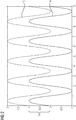
- the curve 14 shows an excitation force generated by a conventional exciter device according to the state of the art.
- the sinusoidal excitation force oscillates essentially around zero, resulting in an alternating push-and-pull-operation on the blade.
- the curve 15, however, shows a sinusoidal excitation force generated by an exciter device 1 according to the invention.
- the pretension provided by the pretensioning device 13 acts as an offset 16 such that the sign of the excitation force is always "plus", resulting in the excitation force only applying in the pulling direction. In this manner, when using a gearbox 8, no gearbox reversals occur, while, in preferred embodiments, when using the flexible coupling element 12 fixed to the pulley 11, this construction becomes feasible.
- Fig. 3 shows a first embodiment of an exciter device 1a.
- steel wires will be exemplarily used as the flexible coupling element 12 and the flexible pretensioning element 17, where applicable.
- the steel wire 18 is fixed to the pulley 11 such that the reversingly operated motor 3 acts to wind and unwind the steel wire 18 from the pully 11.
- the pretensioning device 13 comprises a freely suspended mass 20 fixed to another steel wire 19 acting as a flexible pretensioning element 17.
- the steel wire 19 is also fixed to the pulley 11, providing the pretension to the pulley 11, the motor shaft and the coupling element 12, that is, the steel wire 18, keeping it pretensioned.
- the pulley 11 may provide tracks for both steel wires 18, 19.
- Fig. 4 shows the use of an additional pulley 21 for the steel wire 19, for example, to place the freely suspended mass 20 horizontally beneath the motor 3.
- the blade 2 to be tested is shown in greater extent.
- the blade root is securely fixed in a concrete block 22.
- the blade 2 is received by the transfer device 10 at a certain position, such that the exerted excitation force may cause the blade to oscillate as indicated by arrows 23.
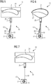
- Fig. 5 shows a second embodiment of an exciter device 1b according to the invention.
- the transfer device 10 comprises a wooden yoke 24 in which the blade 2 to be tested is received.
- the steel wire 18 acting as flexible coupling element 12 is attached to the yoke 24 by an attachment means 25 having a through-hole for attachment of the steel wire 18 and also comprising the load cell 7.
- the load cell 7 may be integrated into the attachment means 25 also in each of the other embodiments, although this will not be shown for reasons of clarity and comprehensibility.
- the pretension device 13 in this embodiment comprises, again, a steel wire 19 as a pretensioning element, into which a spring 26 is integrated.
- the steel wire 19 is fixed to the steel wire 18 close to the attachment means 25, such that the pretensioning force results.
- Fig. 6 shows a third embodiment of an exciter device 1c according to the invention, which differs from the embodiment of fig. 5 in that the transfer device 10 comprises a sling 27 slung around the blade 2.
- the sling 27 may, for example, pass through another through-hole of the attachment means 25.
- the steel rope 19, in this case, is also fixed to the attachment means.
- Fig. 7 shows a fourth embodiment of an exciter device 1d according to the current invention.
- the motor 3 itself forms part of the pretensioning device 13, since it provides the pretension itself as an electrical torque, in particular controlled by the control device 4.
- This embodiment of the pretensioning device 13 may also be combined with other concrete realizations of the pretensioning device 13; Additionally, instead of the wooded yoke 24, also other transfer devices 10 may be used, for example the sling 27.
- FIG. 8 A further, fifth embodiment of an exciter device 1e according to the invention is shown in fig. 8 .
- the spring 26 uses a concrete block 28 as a counter-bearing to provide the pretension.
Landscapes
- Physics & Mathematics (AREA)
- General Physics & Mathematics (AREA)
- Wind Motors (AREA)
- Investigating Strength Of Materials By Application Of Mechanical Stress (AREA)
Abstract
Description
- The invention concerns an exciter device for fatigue testing of a blade of a wind turbine, comprising an actuator, in particular a motor, for generating a periodic excitation force and a coupling device for coupling the motor to a blade to be tested. The invention further concerns a method for fatigue testing of a blade of a wind turbine, wherein a periodic excitation force is generated by an actuator, in particular a motor, and applied to the blade by the coupling device for coupling the actuator to the blade.
- Blades used in wind turbines are required to withstand varying, strong forces over a long time period. Thus, comprehensive testing regarding the mechanical properties of the blade, in particular fatigue, is performed. In particular, an exciter device is coupled to the blade such that an excitation force generated by the actuator, in particular the motor, acts on a blade to be tested. The purpose of such an exciter device may, for example, be to apply a sinusoidal excitation force on the blade with a frequency near or corresponding to the blade's eigenfrequency (taking into account the effects of exciter itself), using, for example, several million cycles. The position along the length of the blade where the excitation force acts may be suitably chosen. During such a fatigue test, which may take a long time to perform, for example up to a few months, the tip of the blade may oscillate over several meters.
- A known exciter device for a blade comprises a servo motor and a coupling device, wherein the coupling device may comprise a gearbox, an exciter arm and a pushrod. Such an exciter device is for example described in http://www.blaest.com/news-2/176-blaest-developed-a-new-electro-mechanical-exciter-for-fatigue-testing. In this exciter device, the electrical motor applies a reversing torque onto the input shaft of the gearbox, which converts the low torque and high speed from the input shaft into high torque and low speed on the output shaft. A torque arm is clamped to the output shaft, moving up and down by, for example, 30 °. By means of flexible connections, such as swivel bearings, a push-pull rod is connected between the torque arm and the blade and thereby able to transfer the excitation force from the exciter device to the blade.
- However, several problems exist when using such an exciter device. A first problem is wear. For each direction change between a pulling direction and a pushing direction, the teeth of the gear in the gearbox will change their engagement side, since the teeth have to interact with the previously opposite teeth. Since there is always some backlash in the gearbox, there will be movement and thus a characterizing clicking sound. These gearbox reversals will, over time, wear out the gearbox. Another problem regarding these gearbox reversals is that the sinusoidal force to be applied is noisy and will impact test quality and time.
- Another problem is the cost of the exciting device. Not only is the servo motor used more expensive than a standard motor, but also the gearbox, exciter arm and pushrod are expensive. It is noted that a servo motor is used since the motor needs to have a low motor shaft inertia to reduce the above-mentioned teeth wear.
- A third problem is the time needed for fatigue testing. In particular, the mass of the exciter arm and the pushrod and the geared motor shaft inertia have a significant impact on the test result. A flapwise blade test takes approximately three months to conduct, depending on the eigenfrequency. The more mass is added to the blade the more time it will take to test the blade. Since the eigenfrequency is the square root of the equivalent stiffness of the blade divided by the equivalent mass of the blade, test duration may rise significantly when adding additional mass.
- Finally, the moment distribution along the blade is also affected based on any additional masses, which cause the blade to bend in different ways. During the blade fatigue test, hard constraints to the bending exist for each, for example, half meter along the blade, which must be complied with. If too much mass is added by the exciter device, this may result in overtesting of certain areas of the blade.
- In summary, the existing excitation method requires an expensive gear and motor type as well as a heavy arm and pushrod. Furthermore, noise from the gearbox reversals wears the gears and secondly causes a noisy excitation force input to the blade. Finally, the heavy arm/pushrod and geared motor shaft prolong the test time and cause potential overtesting.
- It is thus an object of the current invention to provide an improved exciter device, in particular being less subject to wear, producing a less noisy excitation force and adding less mass to the blade.
- This object is achieved by providing an exciter device and a method according to the independent claims. Advantageous embodiments are described in the dependent claims.
- In an exciter device as initially described, according to the invention, the exciter device comprises a pretensioning device applying a pretension such that the excitation force only acts in a pulling or pushing direction over the whole period.
- The pretension can be understood as an offset for the periodic excitation force, such that the periodic excitation force never changes sign. In particular, the periodic, preferably sinusoidal excitation force may only act in a pulling direction, since any mass added to the blade will also act in this direction, such that, in some cases, less pretension may be applied.
- An idea of the current invention is thus that the excitation force acting on the blade does not change sign, for example, is always positive. This is a fundamentally new approach on how fatigue testing excitation should work, since known approaches always assumed that, to successfully excite a blade, it would be required to both push and pull. However, the main purpose is to apply a sinusoidal force to the blade. This can also be achieved in the current invention, using the offset provided by the pretension. In this manner, if a gearbox is used, gearbox reversals may be avoided, thus also reducing the detrimental effects discusses above. Additionally, however, the concept of only having the excitation force act in one direction and not changing sign allows for advantageous new designs of exciter devices, as laid out in detail below.
- Generally, in many embodiments, the exciter device further comprises a control device, the control device being configured to control the actuator, in particular the motor, to generate the periodic excitation force for the blade having a predetermined frequency, in particular calculated from an eigenfrequency of the blade and/or depending on a coupling point of the blade. Often, the exciter device will also comprise a load cell providing measurement data on the excitation force actually exerted. In this manner, feedback control may be executed by the control device, since the measurement data are provided to the control device. As an alternative to the load cell, of course, also other force measurement devices may be employed.
- In a less preferred embodiment, the coupling device may comprise a gearbox. For example, the already known design, wherein the coupling device additionally comprises an exciter arm (torque arm) and a pushrod may be used. The aim of the current invention in this case is to prevent gearbox reversals of the gearbox connected to the motor shaft as input shaft. The pretensioning device acts on the motor shaft and applies a pretension such that no gear reversals appear. That is, during the generation of the periodic excitation force, the teeth of the gears of the gearbox remain engaged, never coming in contact with the opposite teeth. In this manner, wear of the gearbox and noisiness of the excitation force can be greatly reduced.
- In the embodiment having a gearbox, since the pretension is applied to the motor shaft, preferably, the pretension device may comprise the motor itself, applying at least a part of the pretension, in particular using the control device to accordingly control the motor. However, pretension may also, at least in part, be applied by a separate member of the pretension device, for example a spring or a piston.
- However, in an especially preferred embodiment of the current invention, the coupling device comprises,
- a transfer device for mounting to the blade to transfer the excitation force to the blade,
- a pulley mounted to a actuator shaft of the actuator, and
- a flexible coupling element for coupling the pulley to the transfer device, the pulley being configured to wind the wire to transfer the excitation force,
- wherein the coupling element is pretensioned by the pretensioning device.
- The basic idea of the current invention, that is, to provide an excitation force, in particular a sinusoidal excitation force, never changing sign, which therefore is applied only in a pushing or, preferably, pulling direction, can be exploited to provide a completely new design of an exciter device for fatigue testing. In this design, instead of the gearbox, a pulley is used, wherein the diameter of the pulley is chosen to obtain a certain winding speed (meters/second) at a nominal rotation speed (rpm). Since the force only acts in one direction, in this case the pulling direction, a flexible coupling element may be used to couple the pulley to the blade.
- The flexible coupling element may, in particular, be wire-like or belt-like. That is, the flexible coupling element is elongated, at least essentially inelastic in its longitudinal direction and flexible perpendicular to the longitudinal direction. In particular, the coupling element may be chosen from the group comprising a steel wire, a rope, a belt and a fiber.
- The coupling element is fixed to the pulley, wherein the pulley may have a track for the coupling element or each coupling element fixed to it. The coupling element is also attached to the transfer device, completing the coupling. In preferred embodiments, the pulley may be placed below the contact point on the blade, however, additional pulleys may be used to redirect the flexible coupling element, in particular to direct the excitation force such that it acts vertically on the blade in the pulling direction. In operation, due to the coupling element being fixed to the pulley, the periodic torque of the actuator results in repeatedly winding and unwinding the flexible coupling element to and from the pulley. Since the flexible coupling element (and thus the pulley and actuator shaft, in particular motor shaft) are pretensioned by virtue of the pretensioning device, each rotating movement of the pulley and thus each winding of the coupling device results in a change in the (pulling) excitation force exerted on the blade.
- This design of the exciter device may shortly be described as being an exciter device for fatigue testing of a blade of a wind turbine, comprising an actuator, in particular a motor, for generating a periodic excitation force and a coupling device for coupling the actuator to a blade to be tested, which is characterized in that the coupling device comprises a transfer device for mounting to the blade to transfer the excitation force to the blade, a pulley mounted to a actuator shaft of the actuator, and a flexible coupling element for coupling the pulley to the transfer device, the pulley being configured to wind the wire to transfer the excitation force, wherein the coupling element is pretensioned by a pretensioning device.
- The advantages of the concrete construction using a pulley are, firstly, that no gearbox is needed, such that no gearbox reversals occur anyway. The wear is thus reduced to the wear of the at least one pulley and coupling element. Additionally, by removing the exciter arm, the pushrod and the geared motor shaft inertia, the equivalent mass is reduced, such that the eigenfrequency of the arrangement is increased and time for fatigue testing can be reduced. Thirdly, the quality of the fatigue test is improved since the exciter device does not introduce a large mass and inertia at a single point.
- In an advantageous embodiment, the motor may be a three-phase induction motor. That is, the invention allows for the use of a cheap, standard three-phase induction motor instead of servo motor, such that the cost of the exciter device may be further reduced.
- In a concrete embodiment, the pretension device may comprise a spring or a mass or a piston, wherein the pretension is applied by using a flexible pretensioning element fixed to the pulley. The flexible pretensioning element, which is an additional flexible coupling element, may also be, as described with respect to the flexible coupling element, wire-like or belt-like, and is also fixed to the pulley, such that, due to the attachment to the spring, mass or piston, a pretensioning force acts on the pulley, also tensioning the flexible coupling element. In particular, the spring may be attached to the pretensioning element and a counter-bearing, for example a concrete block or the like, such that pretension is applied to the pulley and thus to the actuator shaft and the coupling element. If a mass is used, the freely suspended mass may be attached to the pretensioning element, such that gravity provides the pretensioning force. It is noted that the counter-bearing may, of course, comprise a part of the pretensioning element if, for example, a spring is integrated into the pretensioning element.
- In an especially preferred design, the counter-bearing may comprise the coupling element and/or an attachment means for the coupling element and/or the transfer device is used as the counter-bearing. In this manner, a very compact exciter device results, such that less room is needed. In essence, in this embodiment, the blade itself provides the main mass for the counter-bearing.
- Alternatively or additionally, the pretensioning device may comprise the actuator applying at least a part of the pretension, in particular using the control device to accordingly control the actuator. In this case, if the actuator applies the whole pretension, no additional members for the pretensioning device are required, also allowing for a very compact design. The pretension may, for example, be realized by adding an offset to the control of the actuator.
- The transfer device may comprise, as already known from the state of the art, a yoke. However, in a preferred embodiment, the transfer device may also comprise a sling to be slung around the blade, since, in this embodiment, the excitation force only acts as a pulling force. The usage of a sling further reduces mass, complexity and cost. The sling may, comparable to the flexible coupling element and the flexible pretensioning element, be made of a wire, in particular a steel wire, a rope, a belt or a fiber material.
- The coupling element may be attached to the transfer device by an attachment means, comprising at least one through-hole for fixing the coupling element. Preferably, if the transfer device comprises a sling as described above, the attachment means may comprise an additional through-hole for the sling. As has already been discussed, the exciter device may comprise a load cell, in particular connected to the control device. The control device may use the measurement data for feedback control.
- In an advantageous embodiment, the load cell may be comprised by the attachment means. The position of the attachment means is an ideal spot for providing a force measurement to be used in controlling the exciter device. Thus, the load cell may be integrated into the attachment means or even for the attachment means.
- The invention further concerns a method for fatigue testing of a blade of a wind turbine, wherein a periodic excitation force is generated by an actuator, in particular a motor, and applied to the blade by a coupling device for coupling the actuator to the blade, wherein a pretension is applied to the blade such that the excitation force only acts in pulling or pushing direction over the whole period of the periodic excitation force. All features and remarks regarding the exciter device according to the invention also apply to the method according to the invention, such that the same advantages are achieved. In particular, an exciter device according to the invention is used in the method according to the invention.
- Further details and advantages become apparent from the following description of concrete embodiments taken in conjunction with the drawings, in which:
- Fig. 1
- shows a principle drawing of an exciter device according to the invention,
- Fig. 2
- is a graph showing a conventionally applied excitation force and an excitation force applied according to the current invention,
- Fig. 3
- shows a first embodiment of an exciter device according to the invention,
- Fig. 4
- shows a detail regarding the first embodiment,
- Fig. 5
- shows a second embodiment of an exciter device according to the invention,
- Fig. 6
- shows a third embodiment of an exciter device according to the invention,
- Fig. 7
- shows a fourth embodiment of an exciter device according to the invention,
- Fig. 8
- shows a fifth embodiment of an exciter device according to the invention, and
- Fig. 9
- shows a sixth embodiment of an exciter device according to the invention.
-
Fig. 1 shows the general structure of anexciter device 1 according to the current invention. Theexciter device 1 is to be used for fatigue testing ablade 2 by exerting a periodic, in this case sinusoidal, excitation force on the blade at a certain position along theblade 2. To generate this excitation force, theexciter device 1 generally comprises as an actuator amotor 3, in this case a three-phase induction motor, which is controlled by acontrol device 4. Themotor 3, outputting a certain torque at amotor shaft 5, is coupled to theblade 2 using a coupling device generally indicated at 6. Thecoupling device 6 generally comprises at least oneload cell 7 measuring the actual excitation force, wherein the corresponding measurement data is applied to thecontrol device 4, enabling feedback control. - Since the
motor 3 outputs a relatively low torque at relatively high rotation speed (rpm), this output is to be converted to a certain applied pulling speed/force on the blade by a conversion means. Regarding the current invention, two options exist. - In a first embodiment, which is less preferred, a
gearbox 8 is used, whose output shaft supplies a higher output torque to amechanical arrangement 9 comprising an exciter arm and a pushrod (which, in this case, may be more suitably termed pullrod). The latter is attached to theblade 2 using atransfer device 10, in this less preferred embodiment a yoke or generally a clamp. - In a preferred second option, a
pulley 11 is attached to themotor shaft 5, to which aflexible coupling element 12, for example a steel wire, a rope or a belt, is fixed. The other end of the flexible coupling element is attached to thetransfer device 10 via an attachment means comprising theload cell 7. - Essential for the feasibility of the second option is a
pretensioning device 13, which acts at least on themotor shaft 5, providing a pretension such that the excitation force only acts in a pulling direction over the whole period of the sinusoidal wave form. In other words, the pretension can be understood as an offset for the periodic excitation force, such that the periodic excitation force never changes sign. - This is illustrated in the graph of
fig. 2 , wherein the excitation force (in kN) is plotted against time. Thecurve 14 shows an excitation force generated by a conventional exciter device according to the state of the art. As can be seen, the sinusoidal excitation force oscillates essentially around zero, resulting in an alternating push-and-pull-operation on the blade. Thecurve 15, however, shows a sinusoidal excitation force generated by anexciter device 1 according to the invention. As can be seen, the pretension provided by thepretensioning device 13 acts as an offset 16 such that the sign of the excitation force is always "plus", resulting in the excitation force only applying in the pulling direction. In this manner, when using agearbox 8, no gearbox reversals occur, while, in preferred embodiments, when using theflexible coupling element 12 fixed to thepulley 11, this construction becomes feasible. - The following figures show concrete embodiments of an
exciter device 1 according to the invention. -
Fig. 3 shows a first embodiment of anexciter device 1a. In this embodiment, and in the following embodiments, steel wires will be exemplarily used as theflexible coupling element 12 and theflexible pretensioning element 17, where applicable. As can be seen, in the first concrete embodiment, thesteel wire 18 is fixed to thepulley 11 such that the reversingly operatedmotor 3 acts to wind and unwind thesteel wire 18 from thepully 11. Thepretensioning device 13 comprises a freely suspendedmass 20 fixed to anothersteel wire 19 acting as aflexible pretensioning element 17. Thesteel wire 19 is also fixed to thepulley 11, providing the pretension to thepulley 11, the motor shaft and thecoupling element 12, that is, thesteel wire 18, keeping it pretensioned. Thepulley 11 may provide tracks for bothsteel wires -
Fig. 4 shows the use of anadditional pulley 21 for thesteel wire 19, for example, to place the freely suspendedmass 20 horizontally beneath themotor 3. - Returning to
fig. 3 , also theblade 2 to be tested is shown in greater extent. The blade root is securely fixed in aconcrete block 22. Theblade 2 is received by thetransfer device 10 at a certain position, such that the exerted excitation force may cause the blade to oscillate as indicated byarrows 23. -
Fig. 5 shows a second embodiment of anexciter device 1b according to the invention. In this case, thetransfer device 10 comprises awooden yoke 24 in which theblade 2 to be tested is received. Thesteel wire 18 acting asflexible coupling element 12 is attached to theyoke 24 by an attachment means 25 having a through-hole for attachment of thesteel wire 18 and also comprising theload cell 7. Please note that theload cell 7 may be integrated into the attachment means 25 also in each of the other embodiments, although this will not be shown for reasons of clarity and comprehensibility. - The
pretension device 13 in this embodiment comprises, again, asteel wire 19 as a pretensioning element, into which aspring 26 is integrated. Thesteel wire 19 is fixed to thesteel wire 18 close to the attachment means 25, such that the pretensioning force results. -
Fig. 6 shows a third embodiment of an exciter device 1c according to the invention, which differs from the embodiment offig. 5 in that thetransfer device 10 comprises asling 27 slung around theblade 2. Thesling 27 may, for example, pass through another through-hole of the attachment means 25. Additionally, thesteel rope 19, in this case, is also fixed to the attachment means. -
Fig. 7 shows a fourth embodiment of anexciter device 1d according to the current invention. In this embodiment, which uses thewooden yoke 24, themotor 3 itself forms part of thepretensioning device 13, since it provides the pretension itself as an electrical torque, in particular controlled by thecontrol device 4. This embodiment of thepretensioning device 13 may also be combined with other concrete realizations of thepretensioning device 13; Additionally, instead of thewooded yoke 24, alsoother transfer devices 10 may be used, for example thesling 27. - A further, fifth embodiment of an
exciter device 1e according to the invention is shown infig. 8 . In this variant, thespring 26 uses aconcrete block 28 as a counter-bearing to provide the pretension. - As the sixth embodiment of an
exciter device 1f according to the invention infig. 9 shows, again, also asling 27 may be used as part of thetransfer device 10. - Although the present invention has been described in detail with reference to the preferred embodiment, the present invention is not limited by the disclosed examples from which the skilled person is able to derive other variations without departing from the scope of the invention.
Claims (15)
- Exciter device (1, 1a, 1b, 1c, 1d, 1e, 1f) for fatigue testing of a blade (2) of a wind turbine, comprising an actuator, in particular a motor (3), for generating a periodic excitation force and a coupling device (6) for coupling the actuator to a blade (2) to be tested, characterised in that the exciter device (1, 1a, 1b, 1c, 1d, 1e, 1f) comprises a pretensioning device (13) applying a pretension such that the excitation force only acts in a pulling or pushing direction over the whole period.
- Exciter device (1, 1a, 1b, 1c, 1d, 1e, 1f) according to claim 1, characterised in that the exciter device (1, 1a, 1b, 1c, 1d, 1e, 1f) further comprises a control device (4), the control device (4) being configured to control the actuator to generate the periodic excitation force for the blade (2) having a predetermined frequency, in particular calculated from an eigenfrequency of the blade (2) and/or depending on a coupling point of the blade (2).
- Exciter device (1, 1a, 1b, 1c, 1d, 1e, 1f) according to claim 1 or 2, characterised in that the coupling device (6) comprises a gearbox (8).
- Exciter device (1, 1a, 1b, 1c, 1d, 1e, 1f) according to claim 1 or 2, characterised in that the coupling device (6) comprises:- a transfer device (10) for mounting to the blade (2) to transfer the excitation force to the blade (2),- a pulley (11) mounted to a actuator shaft of the actuator, and- a flexible coupling element (12) for coupling the pulley (11) to the transfer device (10), the pulley (11) being configured to wind the wire to transfer the excitation force,- wherein the coupling element (12) is pretensioned by the pretensioning device (13).
- Exciter device (1, 1a, 1b, 1c, 1d, 1e, 1f) according to claim 4, characterised in that the actuator is a three-phase induction motor (3) and/or the coupling element (12) is chosen from the group comprising a steel wire (18), a rope, a belt and a fiber.
- Exciter device (1, 1a, 1b, 1c, 1d, 1e, 1f) according to claim 4 or 5, characterised in that the pretensioning device (13) comprises a spring (26) or a mass (20) or piston, wherein the pretension is applied by using a flexible pretensioning element (17) fixed to the pulley (11).
- Exciter device (1, 1a, 1b, 1c, 1d, 1e, 1f) according to claim 6, characterised in that the spring (26) is attached to the pretensioning element (17) and a counter-bearing or that the freely suspended mass (20) is attached to the pretensioning element (17).
- Exciter device (1, 1a, 1b, 1c, 1d, 1e, 1f) according to claim 7, characterised in that the counter-bearing comprises the coupling element (12) and/or an attachment means (25) for the coupling element (12) and/or the transfer device (10) is used as the counter-bearing.
- Exciter device (1, 1a, 1b, 1c, 1d, 1e, 1f) according to any of the claim 4 to 8, characterised in that the pretensioning device (13) comprises the actuator applying at least a part of the pretension, in particular using the control device (4) to accordingly control the actuator.
- Exciter device (1, 1a, 1b, 1c, 1d, 1e, 1f) according to one of the claims 4 to 9, characterised in that the transfer device (10) comprises a yoke (24) and/or a sling (27) to be slung around the blade (2).
- Exciter device (1, 1a, 1b, 1c, 1d, 1e, 1f) according to one of the claims 4 to 10, characterised in that the coupling element (12) is attached to the transfer device (10) by an attachment means (25), comprising at least one through-hole for fixing the coupling element (12).
- Exciter device (1, 1a, 1b, 1c, 1d, 1e, 1f) according to claim 11, characterised in that, if the transfer device (10) comprises a sling (27) according to claim 10, the attachment means (25) comprises an additional through-hole for the sling.
- Exciter device (1, 1a, 1b, 1c, 1d, 1e, 1f) according to one of the preceding claims, characterised in that it comprises a load cell (7), in particular connected to the control device (4).
- Method for fatigue testing of a blade (2) of a wind turbine, wherein a periodic excitation force is generated by an actuator, in particular a motor (3), and applied to the blade (2) by a coupling device (6) for coupling the actuator to the blade (2), characterised in that a pretension is applied to the blade (2) such that the excitation force only acts in a pulling or pushing direction over the whole period.
- Method according to claim 14, characterised in that an exciter device (1, 1a, 1b, 1c, 1d, 1e, 1f) according to any of the claim 1 to 13 is used.
Priority Applications (7)
| Application Number | Priority Date | Filing Date | Title |
|---|---|---|---|
| PT191705086T PT3730916T (en) | 2019-04-23 | 2019-04-23 | Exciter device and method for fatigue testing of a blade of a wind turbine |
| EP19170508.6A EP3730916B1 (en) | 2019-04-23 | 2019-04-23 | Exciter device and method for fatigue testing of a blade of a wind turbine |
| DK19170508.6T DK3730916T3 (en) | 2019-04-23 | 2019-04-23 | Excitation device and method for fatigue testing of a blade of a wind turbine |
| ES19170508T ES2902804T3 (en) | 2019-04-23 | 2019-04-23 | Exciter device and method for fatigue testing of a wind turbine blade |
| US17/603,364 US12130211B2 (en) | 2019-04-23 | 2020-03-23 | Exciter device and method for fatigue testing of a blade of a wind turbine |
| PCT/EP2020/058033 WO2020216545A1 (en) | 2019-04-23 | 2020-03-23 | Exciter device and method for fatigue testing of a blade of a wind turbine |
| CN202080030825.1A CN113677974B (en) | 2019-04-23 | 2020-03-23 | Exciter device and method for fatigue testing of blades of a wind turbine |
Applications Claiming Priority (1)
| Application Number | Priority Date | Filing Date | Title |
|---|---|---|---|
| EP19170508.6A EP3730916B1 (en) | 2019-04-23 | 2019-04-23 | Exciter device and method for fatigue testing of a blade of a wind turbine |
Publications (2)
| Publication Number | Publication Date |
|---|---|
| EP3730916A1 true EP3730916A1 (en) | 2020-10-28 |
| EP3730916B1 EP3730916B1 (en) | 2021-10-13 |
Family
ID=66248571
Family Applications (1)
| Application Number | Title | Priority Date | Filing Date |
|---|---|---|---|
| EP19170508.6A Active EP3730916B1 (en) | 2019-04-23 | 2019-04-23 | Exciter device and method for fatigue testing of a blade of a wind turbine |
Country Status (7)
| Country | Link |
|---|---|
| US (1) | US12130211B2 (en) |
| EP (1) | EP3730916B1 (en) |
| CN (1) | CN113677974B (en) |
| DK (1) | DK3730916T3 (en) |
| ES (1) | ES2902804T3 (en) |
| PT (1) | PT3730916T (en) |
| WO (1) | WO2020216545A1 (en) |
Cited By (4)
| Publication number | Priority date | Publication date | Assignee | Title |
|---|---|---|---|---|
| US11754053B2 (en) | 2019-10-09 | 2023-09-12 | Siemens Gamesa Renewable Energy A/S | Rotor blade fatigue testing |
| CN117321401A (en) * | 2021-05-19 | 2023-12-29 | 西门子歌美飒可再生能源公司 | Test arrangement and method for fatigue testing wind turbine blades |
| US11940355B2 (en) | 2019-10-28 | 2024-03-26 | Siemens Gamesa Renewable Energy A/S | Wind turbine rotor blade load emulator arrangement |
| DE102022133002A1 (en) | 2022-12-12 | 2024-06-13 | CFM Schiller GmbH | Test device for rotor blades of a wind turbine |
Families Citing this family (2)
| Publication number | Priority date | Publication date | Assignee | Title |
|---|---|---|---|---|
| EP4148407A1 (en) * | 2021-09-13 | 2023-03-15 | Nordex Energy SE & Co. KG | A method for controlling the quality of a wind turbine rotor blade |
| CN119223566B (en) * | 2024-12-03 | 2025-07-08 | 上海中帧机器人控制技术发展有限公司 | Wind power blade double-shaft fatigue testing device and testing method |
Citations (4)
| Publication number | Priority date | Publication date | Assignee | Title |
|---|---|---|---|---|
| US20100263448A1 (en) * | 2007-12-14 | 2010-10-21 | Alliance For Sustainable Energy, Llc. | Dual- axis resonance testing of wind turbine blades |
| DE102012205153A1 (en) * | 2012-03-29 | 2013-10-02 | Repower Systems Se | Test device and vibration mass arrangement for a rotor blade of a wind turbine |
| EP2741069A1 (en) * | 2012-12-05 | 2014-06-11 | Industrieanlagen-Betriebsgesellschaft mbH | Test bench for a rotor blade or a rotor blade segment, arrangement comprising such a test bench and test method |
| US20160109319A1 (en) * | 2014-10-17 | 2016-04-21 | Korea Institute Of Machinery & Materials | Method and apparatus of moment calibration for resonance fatigue test |
Family Cites Families (16)
| Publication number | Priority date | Publication date | Assignee | Title |
|---|---|---|---|---|
| WO2008145727A1 (en) * | 2007-05-30 | 2008-12-04 | Vestas Wind Systems A/S | A fatigue testing device for wind turbine blade testing, a method of testing wind turbine blades and a control system for a blade testing actuator |
| WO2009097055A2 (en) * | 2007-12-13 | 2009-08-06 | Alliance For Sustainable Energy, Llc | Wind turbine blade testing system using base excitation |
| GB0804488D0 (en) * | 2008-03-12 | 2008-04-16 | Rolls Royce Plc | A vibration test arrangement |
| WO2009135136A2 (en) * | 2008-05-02 | 2009-11-05 | Alliance For Sustainable Energy, Llc | Base excitation testing system using spring elements to pivotally mount wind turbine blades |
| EP2315940B1 (en) * | 2008-06-30 | 2016-08-03 | Vestas Wind Systems A/S | A test rig for testing blades for a wind turbine |
| CA2797639A1 (en) * | 2010-01-19 | 2011-07-28 | Vestas Wind Systems A/S | Systems and methods for performing structural tests on wind turbine blades |
| DE102012025649A1 (en) * | 2012-12-05 | 2015-08-06 | Industrieanlagen-Betriebsgesellschaft Mbh | Test bench for a rotor blade, arrangement with such a test bench and method for operating such a test bench |
| DE102012111838B4 (en) * | 2012-12-05 | 2014-12-04 | Industrieanlagen-Betriebsgesellschaft Mbh | Test bench for a rotor blade, arrangement with such a test bench and method for operating such a test bench |
| WO2016045684A1 (en) * | 2014-09-26 | 2016-03-31 | Vestas Wind Systems A/S | Fatigue testing of a wind turbine blade |
| DE102016005586A1 (en) * | 2016-05-04 | 2017-11-09 | Wolfram Tessendorf | Test device for rotor blades of wind turbines |
| WO2018099531A2 (en) * | 2016-11-30 | 2018-06-07 | Vestas Wind Systems A/S | Torsional testing of a wind turbine blade |
| DE102018218515A1 (en) * | 2018-10-29 | 2020-04-30 | Fraunhofer-Gesellschaft zur Förderung der angewandten Forschung e.V. | Method and test device for testing rotor blades |
| CN109682702B (en) * | 2018-12-10 | 2020-03-20 | 湘潭大学 | A simulation test system for thermal barrier coatings on turbine blades |
| ES2937739T3 (en) * | 2019-10-09 | 2023-03-30 | Siemens Gamesa Renewable Energy As | Rotor blade fatigue test |
| DK3816603T3 (en) * | 2019-10-28 | 2023-06-12 | Siemens Gamesa Renewable Energy As | Equipment for a load simulator for a wind turbine rotor blade |
| DE102020200822A1 (en) * | 2020-01-23 | 2021-07-29 | Fraunhofer-Gesellschaft zur Förderung der angewandten Forschung eingetragener Verein | Mechanical test device and method for testing bar-shaped test objects, in particular rotor blades of wind turbines |
-
2019
- 2019-04-23 ES ES19170508T patent/ES2902804T3/en active Active
- 2019-04-23 DK DK19170508.6T patent/DK3730916T3/en active
- 2019-04-23 EP EP19170508.6A patent/EP3730916B1/en active Active
- 2019-04-23 PT PT191705086T patent/PT3730916T/en unknown
-
2020
- 2020-03-23 US US17/603,364 patent/US12130211B2/en active Active
- 2020-03-23 WO PCT/EP2020/058033 patent/WO2020216545A1/en not_active Ceased
- 2020-03-23 CN CN202080030825.1A patent/CN113677974B/en active Active
Patent Citations (4)
| Publication number | Priority date | Publication date | Assignee | Title |
|---|---|---|---|---|
| US20100263448A1 (en) * | 2007-12-14 | 2010-10-21 | Alliance For Sustainable Energy, Llc. | Dual- axis resonance testing of wind turbine blades |
| DE102012205153A1 (en) * | 2012-03-29 | 2013-10-02 | Repower Systems Se | Test device and vibration mass arrangement for a rotor blade of a wind turbine |
| EP2741069A1 (en) * | 2012-12-05 | 2014-06-11 | Industrieanlagen-Betriebsgesellschaft mbH | Test bench for a rotor blade or a rotor blade segment, arrangement comprising such a test bench and test method |
| US20160109319A1 (en) * | 2014-10-17 | 2016-04-21 | Korea Institute Of Machinery & Materials | Method and apparatus of moment calibration for resonance fatigue test |
Cited By (5)
| Publication number | Priority date | Publication date | Assignee | Title |
|---|---|---|---|---|
| US11754053B2 (en) | 2019-10-09 | 2023-09-12 | Siemens Gamesa Renewable Energy A/S | Rotor blade fatigue testing |
| US11940355B2 (en) | 2019-10-28 | 2024-03-26 | Siemens Gamesa Renewable Energy A/S | Wind turbine rotor blade load emulator arrangement |
| CN117321401A (en) * | 2021-05-19 | 2023-12-29 | 西门子歌美飒可再生能源公司 | Test arrangement and method for fatigue testing wind turbine blades |
| DE102022133002A1 (en) | 2022-12-12 | 2024-06-13 | CFM Schiller GmbH | Test device for rotor blades of a wind turbine |
| EP4386349A1 (en) | 2022-12-12 | 2024-06-19 | CFM Schiller GmbH | Testing device for rotor blades of a wind turbine |
Also Published As
| Publication number | Publication date |
|---|---|
| US20220187157A1 (en) | 2022-06-16 |
| DK3730916T3 (en) | 2021-12-06 |
| WO2020216545A1 (en) | 2020-10-29 |
| EP3730916B1 (en) | 2021-10-13 |
| ES2902804T3 (en) | 2022-03-29 |
| CN113677974A (en) | 2021-11-19 |
| CN113677974B (en) | 2024-11-19 |
| US12130211B2 (en) | 2024-10-29 |
| PT3730916T (en) | 2021-10-27 |
Similar Documents
| Publication | Publication Date | Title |
|---|---|---|
| US12130211B2 (en) | Exciter device and method for fatigue testing of a blade of a wind turbine | |
| EP3805724B1 (en) | Rotor blade fatigue testing | |
| KR102265194B1 (en) | Performance Evaluation Device of Decelerator | |
| JP6723540B2 (en) | Excitation device, vibration measuring system, vibration measuring method, and tension measuring method | |
| US10209160B2 (en) | Fatigue testing of a wind turbine blade | |
| EP2108827B1 (en) | Model Based Wind Turbine Drive Train Vibration Damper | |
| JP5031727B2 (en) | Conversion of mechanical vibration energy to electrical energy | |
| WO2021083638A1 (en) | Wind turbine rotor blade load emulator arrangement | |
| JP2008180118A (en) | Wind power generation device using piezoelectric element | |
| JP2011163521A (en) | Rotary drive unit | |
| GB2519992A (en) | Robotic arm | |
| CN107300414B (en) | A dancing oscillation platform with end excitation | |
| JP5705618B2 (en) | Vibration power generator | |
| CN215004237U (en) | Wind-powered electricity generation blade fatigue test loading device | |
| KR100530867B1 (en) | Complex Piezoelectric Linear Ultrasonic Motor | |
| KR20150059251A (en) | Generator using vibration of engine | |
| Okundaye | Computation of Amplification Factor of the Mechanical Power Amplifier for Different Rope Materials | |
| Okundaye | MEASURING THE AMPLIFICATION FACTOR OF MECHANICAL POWER AMPLIFIER FOR VARYING ROPE MATERIALS | |
| RU2348509C1 (en) | Robot electrical drive | |
| Sarnaik et al. | Footstep Power Generation | |
| JP2009085850A (en) | Fatigue testing equipment | |
| CN120979230A (en) | A piezoelectric energy harvesting device based on a suspension support | |
| TW200925598A (en) | Fatigue test device | |
| RU1779949C (en) | Device for testing flexible cable products for repeated rewinding | |
| US337428A (en) | Adolph osterloh |
Legal Events
| Date | Code | Title | Description |
|---|---|---|---|
| PUAI | Public reference made under article 153(3) epc to a published international application that has entered the european phase |
Free format text: ORIGINAL CODE: 0009012 |
|
| STAA | Information on the status of an ep patent application or granted ep patent |
Free format text: STATUS: THE APPLICATION HAS BEEN PUBLISHED |
|
| AK | Designated contracting states |
Kind code of ref document: A1 Designated state(s): AL AT BE BG CH CY CZ DE DK EE ES FI FR GB GR HR HU IE IS IT LI LT LU LV MC MK MT NL NO PL PT RO RS SE SI SK SM TR |
|
| STAA | Information on the status of an ep patent application or granted ep patent |
Free format text: STATUS: REQUEST FOR EXAMINATION WAS MADE |
|
| 17P | Request for examination filed |
Effective date: 20201204 |
|
| RBV | Designated contracting states (corrected) |
Designated state(s): AL AT BE BG CH CY CZ DE DK EE ES FI FR GB GR HR HU IE IS IT LI LT LU LV MC MK MT NL NO PL PT RO RS SE SI SK SM TR |
|
| GRAP | Despatch of communication of intention to grant a patent |
Free format text: ORIGINAL CODE: EPIDOSNIGR1 |
|
| STAA | Information on the status of an ep patent application or granted ep patent |
Free format text: STATUS: GRANT OF PATENT IS INTENDED |
|
| INTG | Intention to grant announced |
Effective date: 20210518 |
|
| GRAS | Grant fee paid |
Free format text: ORIGINAL CODE: EPIDOSNIGR3 |
|
| GRAA | (expected) grant |
Free format text: ORIGINAL CODE: 0009210 |
|
| STAA | Information on the status of an ep patent application or granted ep patent |
Free format text: STATUS: THE PATENT HAS BEEN GRANTED |
|
| AK | Designated contracting states |
Kind code of ref document: B1 Designated state(s): AL AT BE BG CH CY CZ DE DK EE ES FI FR GB GR HR HU IE IS IT LI LT LU LV MC MK MT NL NO PL PT RO RS SE SI SK SM TR |
|
| REG | Reference to a national code |
Ref country code: GB Ref legal event code: FG4D |
|
| REG | Reference to a national code |
Ref country code: CH Ref legal event code: EP |
|
| REG | Reference to a national code |
Ref country code: PT Ref legal event code: SC4A Ref document number: 3730916 Country of ref document: PT Date of ref document: 20211027 Kind code of ref document: T Free format text: AVAILABILITY OF NATIONAL TRANSLATION Effective date: 20211021 |
|
| REG | Reference to a national code |
Ref country code: DE Ref legal event code: R096 Ref document number: 602019008266 Country of ref document: DE |
|
| REG | Reference to a national code |
Ref country code: IE Ref legal event code: FG4D |
|
| REG | Reference to a national code |
Ref country code: AT Ref legal event code: REF Ref document number: 1438510 Country of ref document: AT Kind code of ref document: T Effective date: 20211115 |
|
| REG | Reference to a national code |
Ref country code: DK Ref legal event code: T3 Effective date: 20211201 |
|
| REG | Reference to a national code |
Ref country code: LT Ref legal event code: MG9D |
|
| REG | Reference to a national code |
Ref country code: NL Ref legal event code: MP Effective date: 20211013 |
|
| REG | Reference to a national code |
Ref country code: AT Ref legal event code: MK05 Ref document number: 1438510 Country of ref document: AT Kind code of ref document: T Effective date: 20211013 |
|
| REG | Reference to a national code |
Ref country code: ES Ref legal event code: FG2A Ref document number: 2902804 Country of ref document: ES Kind code of ref document: T3 Effective date: 20220329 |
|
| PG25 | Lapsed in a contracting state [announced via postgrant information from national office to epo] |
Ref country code: RS Free format text: LAPSE BECAUSE OF FAILURE TO SUBMIT A TRANSLATION OF THE DESCRIPTION OR TO PAY THE FEE WITHIN THE PRESCRIBED TIME-LIMIT Effective date: 20211013 Ref country code: LT Free format text: LAPSE BECAUSE OF FAILURE TO SUBMIT A TRANSLATION OF THE DESCRIPTION OR TO PAY THE FEE WITHIN THE PRESCRIBED TIME-LIMIT Effective date: 20211013 Ref country code: FI Free format text: LAPSE BECAUSE OF FAILURE TO SUBMIT A TRANSLATION OF THE DESCRIPTION OR TO PAY THE FEE WITHIN THE PRESCRIBED TIME-LIMIT Effective date: 20211013 Ref country code: BG Free format text: LAPSE BECAUSE OF FAILURE TO SUBMIT A TRANSLATION OF THE DESCRIPTION OR TO PAY THE FEE WITHIN THE PRESCRIBED TIME-LIMIT Effective date: 20220113 Ref country code: AT Free format text: LAPSE BECAUSE OF FAILURE TO SUBMIT A TRANSLATION OF THE DESCRIPTION OR TO PAY THE FEE WITHIN THE PRESCRIBED TIME-LIMIT Effective date: 20211013 |
|
| PG25 | Lapsed in a contracting state [announced via postgrant information from national office to epo] |
Ref country code: IS Free format text: LAPSE BECAUSE OF FAILURE TO SUBMIT A TRANSLATION OF THE DESCRIPTION OR TO PAY THE FEE WITHIN THE PRESCRIBED TIME-LIMIT Effective date: 20220213 Ref country code: SE Free format text: LAPSE BECAUSE OF FAILURE TO SUBMIT A TRANSLATION OF THE DESCRIPTION OR TO PAY THE FEE WITHIN THE PRESCRIBED TIME-LIMIT Effective date: 20211013 Ref country code: PL Free format text: LAPSE BECAUSE OF FAILURE TO SUBMIT A TRANSLATION OF THE DESCRIPTION OR TO PAY THE FEE WITHIN THE PRESCRIBED TIME-LIMIT Effective date: 20211013 Ref country code: NO Free format text: LAPSE BECAUSE OF FAILURE TO SUBMIT A TRANSLATION OF THE DESCRIPTION OR TO PAY THE FEE WITHIN THE PRESCRIBED TIME-LIMIT Effective date: 20220113 Ref country code: NL Free format text: LAPSE BECAUSE OF FAILURE TO SUBMIT A TRANSLATION OF THE DESCRIPTION OR TO PAY THE FEE WITHIN THE PRESCRIBED TIME-LIMIT Effective date: 20211013 Ref country code: LV Free format text: LAPSE BECAUSE OF FAILURE TO SUBMIT A TRANSLATION OF THE DESCRIPTION OR TO PAY THE FEE WITHIN THE PRESCRIBED TIME-LIMIT Effective date: 20211013 Ref country code: HR Free format text: LAPSE BECAUSE OF FAILURE TO SUBMIT A TRANSLATION OF THE DESCRIPTION OR TO PAY THE FEE WITHIN THE PRESCRIBED TIME-LIMIT Effective date: 20211013 Ref country code: GR Free format text: LAPSE BECAUSE OF FAILURE TO SUBMIT A TRANSLATION OF THE DESCRIPTION OR TO PAY THE FEE WITHIN THE PRESCRIBED TIME-LIMIT Effective date: 20220114 |
|
| REG | Reference to a national code |
Ref country code: DE Ref legal event code: R097 Ref document number: 602019008266 Country of ref document: DE |
|
| PG25 | Lapsed in a contracting state [announced via postgrant information from national office to epo] |
Ref country code: SM Free format text: LAPSE BECAUSE OF FAILURE TO SUBMIT A TRANSLATION OF THE DESCRIPTION OR TO PAY THE FEE WITHIN THE PRESCRIBED TIME-LIMIT Effective date: 20211013 Ref country code: SK Free format text: LAPSE BECAUSE OF FAILURE TO SUBMIT A TRANSLATION OF THE DESCRIPTION OR TO PAY THE FEE WITHIN THE PRESCRIBED TIME-LIMIT Effective date: 20211013 Ref country code: RO Free format text: LAPSE BECAUSE OF FAILURE TO SUBMIT A TRANSLATION OF THE DESCRIPTION OR TO PAY THE FEE WITHIN THE PRESCRIBED TIME-LIMIT Effective date: 20211013 Ref country code: EE Free format text: LAPSE BECAUSE OF FAILURE TO SUBMIT A TRANSLATION OF THE DESCRIPTION OR TO PAY THE FEE WITHIN THE PRESCRIBED TIME-LIMIT Effective date: 20211013 Ref country code: CZ Free format text: LAPSE BECAUSE OF FAILURE TO SUBMIT A TRANSLATION OF THE DESCRIPTION OR TO PAY THE FEE WITHIN THE PRESCRIBED TIME-LIMIT Effective date: 20211013 |
|
| REG | Reference to a national code |
Ref country code: DE Ref legal event code: R082 Ref document number: 602019008266 Country of ref document: DE Representative=s name: SAUTHOFF, KARSTEN, DIPL.-ING. UNIV., DE |
|
| PLBE | No opposition filed within time limit |
Free format text: ORIGINAL CODE: 0009261 |
|
| STAA | Information on the status of an ep patent application or granted ep patent |
Free format text: STATUS: NO OPPOSITION FILED WITHIN TIME LIMIT |
|
| 26N | No opposition filed |
Effective date: 20220714 |
|
| PG25 | Lapsed in a contracting state [announced via postgrant information from national office to epo] |
Ref country code: AL Free format text: LAPSE BECAUSE OF FAILURE TO SUBMIT A TRANSLATION OF THE DESCRIPTION OR TO PAY THE FEE WITHIN THE PRESCRIBED TIME-LIMIT Effective date: 20211013 |
|
| PG25 | Lapsed in a contracting state [announced via postgrant information from national office to epo] |
Ref country code: SI Free format text: LAPSE BECAUSE OF FAILURE TO SUBMIT A TRANSLATION OF THE DESCRIPTION OR TO PAY THE FEE WITHIN THE PRESCRIBED TIME-LIMIT Effective date: 20211013 |
|
| REG | Reference to a national code |
Ref country code: CH Ref legal event code: PL |
|
| REG | Reference to a national code |
Ref country code: BE Ref legal event code: MM Effective date: 20220430 |
|
| PG25 | Lapsed in a contracting state [announced via postgrant information from national office to epo] |
Ref country code: MC Free format text: LAPSE BECAUSE OF FAILURE TO SUBMIT A TRANSLATION OF THE DESCRIPTION OR TO PAY THE FEE WITHIN THE PRESCRIBED TIME-LIMIT Effective date: 20211013 Ref country code: LU Free format text: LAPSE BECAUSE OF NON-PAYMENT OF DUE FEES Effective date: 20220423 Ref country code: LI Free format text: LAPSE BECAUSE OF NON-PAYMENT OF DUE FEES Effective date: 20220430 Ref country code: CH Free format text: LAPSE BECAUSE OF NON-PAYMENT OF DUE FEES Effective date: 20220430 |
|
| PG25 | Lapsed in a contracting state [announced via postgrant information from national office to epo] |
Ref country code: BE Free format text: LAPSE BECAUSE OF NON-PAYMENT OF DUE FEES Effective date: 20220430 |
|
| PG25 | Lapsed in a contracting state [announced via postgrant information from national office to epo] |
Ref country code: IE Free format text: LAPSE BECAUSE OF NON-PAYMENT OF DUE FEES Effective date: 20220423 |
|
| PG25 | Lapsed in a contracting state [announced via postgrant information from national office to epo] |
Ref country code: IT Free format text: LAPSE BECAUSE OF FAILURE TO SUBMIT A TRANSLATION OF THE DESCRIPTION OR TO PAY THE FEE WITHIN THE PRESCRIBED TIME-LIMIT Effective date: 20211013 |
|
| PG25 | Lapsed in a contracting state [announced via postgrant information from national office to epo] |
Ref country code: MK Free format text: LAPSE BECAUSE OF FAILURE TO SUBMIT A TRANSLATION OF THE DESCRIPTION OR TO PAY THE FEE WITHIN THE PRESCRIBED TIME-LIMIT Effective date: 20211013 Ref country code: CY Free format text: LAPSE BECAUSE OF FAILURE TO SUBMIT A TRANSLATION OF THE DESCRIPTION OR TO PAY THE FEE WITHIN THE PRESCRIBED TIME-LIMIT Effective date: 20211013 |
|
| PG25 | Lapsed in a contracting state [announced via postgrant information from national office to epo] |
Ref country code: HU Free format text: LAPSE BECAUSE OF FAILURE TO SUBMIT A TRANSLATION OF THE DESCRIPTION OR TO PAY THE FEE WITHIN THE PRESCRIBED TIME-LIMIT; INVALID AB INITIO Effective date: 20190423 |
|
| PG25 | Lapsed in a contracting state [announced via postgrant information from national office to epo] |
Ref country code: MT Free format text: LAPSE BECAUSE OF FAILURE TO SUBMIT A TRANSLATION OF THE DESCRIPTION OR TO PAY THE FEE WITHIN THE PRESCRIBED TIME-LIMIT Effective date: 20211013 |
|
| PGFP | Annual fee paid to national office [announced via postgrant information from national office to epo] |
Ref country code: DE Payment date: 20250428 Year of fee payment: 7 |
|
| PGFP | Annual fee paid to national office [announced via postgrant information from national office to epo] |
Ref country code: ES Payment date: 20250513 Year of fee payment: 7 Ref country code: DK Payment date: 20250424 Year of fee payment: 7 |
|
| PGFP | Annual fee paid to national office [announced via postgrant information from national office to epo] |
Ref country code: PT Payment date: 20250402 Year of fee payment: 7 |
|
| PGFP | Annual fee paid to national office [announced via postgrant information from national office to epo] |
Ref country code: FR Payment date: 20250424 Year of fee payment: 7 |
|
| PG25 | Lapsed in a contracting state [announced via postgrant information from national office to epo] |
Ref country code: TR Free format text: LAPSE BECAUSE OF FAILURE TO SUBMIT A TRANSLATION OF THE DESCRIPTION OR TO PAY THE FEE WITHIN THE PRESCRIBED TIME-LIMIT Effective date: 20211013 |
|
| PGFP | Annual fee paid to national office [announced via postgrant information from national office to epo] |
Ref country code: GB Payment date: 20260323 Year of fee payment: 8 |