EP3730837A2 - Gas burner bar with fuel injector fixation - Google Patents
Gas burner bar with fuel injector fixation Download PDFInfo
- Publication number
- EP3730837A2 EP3730837A2 EP20170876.5A EP20170876A EP3730837A2 EP 3730837 A2 EP3730837 A2 EP 3730837A2 EP 20170876 A EP20170876 A EP 20170876A EP 3730837 A2 EP3730837 A2 EP 3730837A2
- Authority
- EP
- European Patent Office
- Prior art keywords
- injector
- burner
- air shutter
- gas
- bar
- Prior art date
- Legal status (The legal status is an assumption and is not a legal conclusion. Google has not performed a legal analysis and makes no representation as to the accuracy of the status listed.)
- Granted
Links
Images


Classifications
-
- F—MECHANICAL ENGINEERING; LIGHTING; HEATING; WEAPONS; BLASTING
- F23—COMBUSTION APPARATUS; COMBUSTION PROCESSES
- F23D—BURNERS
- F23D14/00—Burners for combustion of a gas, e.g. of a gas stored under pressure as a liquid
- F23D14/02—Premix gas burners, i.e. in which gaseous fuel is mixed with combustion air upstream of the combustion zone
- F23D14/04—Premix gas burners, i.e. in which gaseous fuel is mixed with combustion air upstream of the combustion zone induction type, e.g. Bunsen burner
- F23D14/10—Premix gas burners, i.e. in which gaseous fuel is mixed with combustion air upstream of the combustion zone induction type, e.g. Bunsen burner with elongated tubular burner head
-
- F—MECHANICAL ENGINEERING; LIGHTING; HEATING; WEAPONS; BLASTING
- F24—HEATING; RANGES; VENTILATING
- F24C—DOMESTIC STOVES OR RANGES ; DETAILS OF DOMESTIC STOVES OR RANGES, OF GENERAL APPLICATION
- F24C3/00—Stoves or ranges for gaseous fuels
- F24C3/08—Arrangement or mounting of burners
- F24C3/085—Arrangement or mounting of burners on ranges
- F24C3/087—Arrangement or mounting of burners on ranges in baking ovens
-
- F—MECHANICAL ENGINEERING; LIGHTING; HEATING; WEAPONS; BLASTING
- F23—COMBUSTION APPARATUS; COMBUSTION PROCESSES
- F23D—BURNERS
- F23D14/00—Burners for combustion of a gas, e.g. of a gas stored under pressure as a liquid
- F23D14/46—Details
- F23D14/48—Nozzles
-
- F—MECHANICAL ENGINEERING; LIGHTING; HEATING; WEAPONS; BLASTING
- F23—COMBUSTION APPARATUS; COMBUSTION PROCESSES
- F23D—BURNERS
- F23D14/00—Burners for combustion of a gas, e.g. of a gas stored under pressure as a liquid
- F23D14/46—Details
- F23D14/62—Mixing devices; Mixing tubes
- F23D14/64—Mixing devices; Mixing tubes with injectors
-
- F—MECHANICAL ENGINEERING; LIGHTING; HEATING; WEAPONS; BLASTING
- F23—COMBUSTION APPARATUS; COMBUSTION PROCESSES
- F23D—BURNERS
- F23D2203/00—Gaseous fuel burners
- F23D2203/007—Mixing tubes, air supply regulation
Definitions
- the present technology relates to improvements in gas burners.
- Gas burner assemblies are used in traditional gas cooking ranges in both broiler and baking configurations. Traditionally these gas burner assemblies are comprised of several components, including a gas burner, a Venturi tube, an air shutter, an injector fitting and an injector.
- the present invention is directed to improvements in gas burners according to the independent claims. These improvements include reduced part counts in injector assemblies, increased reliability, easier assembly, and a reduction in misaligned gas burner problems.
- the invention is an improved injector assembly that is constructed out of two components: an injector fitting and an injector.
- injector is passed through the opening of the air shutter and threaded into the injector fitting.
- the air shutter is sandwiched between the injector and the injector fitting, resulting in a flush placement of the injector against either the wall or raised opening of the air shutter.
- this method of engagement holds the air shutter and the injector assembly in proper position with fewer chances of erroneous placement.
- the mixing unit may comprise elements and features of the injector fitting, air shutter and/or injector disclosed with respect to embodiments of the burner bar.
- top, bottom, front, back, left and right may be used. These terms are only intended to provide relational orientation with respect to one another. For example, any two opposed sides can be a right side and a left side and by changing to an opposed viewpoint, right versus left will be changed. Thus, top, bottom, front, back, left and right should not be considered limiting and are used only to distinguish their relationship to one another.
- a major component of combustion systems is the mixer which mixes fuel gas with combustion air and sends the mixture to the burner at a fixed pressure. Important to the mixing process is the location and alignment of the gas orifice in relation to both the air intake and the Venturi tube. A misaligned or mis-located gas orifice can result in several forms of burner malfunction such as the creation of or increased amount of soot, flashback, and/or flame lifting at the burner.
- FIG. 1 illustrates a standard burner bar 10 in a gas oven utilizing the improved injector assembly of the present invention.
- the gas burner bar 10 generally includes a burner region 20, a Venturi tube 30, an air shutter 40, and an improved injector assembly 50. While the burner bar 10 is depicted as having an L-bend region 60, alternative embodiments allow for a burner bar 10 without a bend (e.g., straight).
- fuel gas is injected into the burner bar 10 via the injector assembly 50; combustion air is drawn into the burner bar 10 at the air shutter 40 due to reduced pressure at the Venturi tube 30, allowing the combustion air to begin mixing with the fuel gas; the combustion air and fuel gas mixture is drawn into and through the Venturi tube 30 and is taken to the burner region where combustion occurs at a plurality of combustion points.
- FIG. 2 illustrates a perspective view of the injector assembly 50 in accordance with embodiments of the invention in an unassembled state
- FIG. 3 illustrates an exploded, close-up view of the unassembled improved injector assembly 50 in conjunction with the air shutter 40 and Venturi tube 30
- the injector assembly 50 is assembled out of two components: an injector fitting 70 and an injector 80.
- the injector fitting 70 has two attachment points (71 & 72).
- the first attachment point 71 is positioned distal to the air shutter 40 and is generally connected to a gas line (not shown) which provides a fuel gas to the burner bar 10.
- the first attachment 71 has male threads, although alternative methods of connection can be utilized.
- the second attachment point 72 of the injector fitting 70 is positioned proximal to the air shutter 40 and, in contrast to the first attachment point 71, has female threads. This is an improvement over previous solutions for injector fittings, which will be illustrated shortly.
- the injector 80 has an orifice 81 through which gas passes through the injector 80 into the air shutter 40 and the Venturi tube 30.
- the injector 80 has a hexagonal head for ease of assembly, but alternative shapes can be utilized (e.g., square).
- This gas flow is controlled by a regulator (not shown) connected to the gas line, the gas line being connected to the first attachment point 71 of the injector fitting 70.
- the injector 80 has male threads that are inserted into the female threads of the second attachment point 72 of the injector fitting 70.
- the air shutter 40 Sandwiched between the injector 80 and the injector fitting 71 is a portion of the air shutter 70. As illustrated in FIG. 3 , the air shutter 40 has a threadless, raised opening 41 through which the injector 80 passes through. After passing through the opening 41, the injector 80 is then threaded into the second attachment point 72 of the injector fitting 70. As a result, when engaged the injector 80 and the injector fitting 70 secure the air shutter 40 in a sandwich manner. Furthermore, this arrangement also serves to hold the injector fitting 70 and injector 80 in proper alignment. In alternative embodiments there is no raised section of the opening 41 in the air shutter 40.
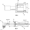
- FIGS. 4 , 5 and 6 illustrate close-up, perspective views of the assembled injector assembly 50 and air shutter 40.
- the head of the injector 80 is held flush against the air shutter 40.
- the head of the injector 80 is properly positioned in the mixing face, labeled as dimension "A.” This proper positioning results in a proper air fuel mixture entering the Venturi tube 30.
- this proper positioning results in a proper air fuel mixture entering the Venturi tube 30.
- this proper positioning of the injector 80 is repeatable during assembly of the gas burner bar 10.
- the injector 80 internally, the proper direction is established in an internal fashion rather than in an external fashion.
- the center line of the injector fitting 70, the injector 80, and the Venturi tube 30 are collinear (labeled as plane "B"), contributing to consistent gas flow and mixing while reducing flashback, flame lifting, and soot created as a result of misaligned injectors.
- the present invention can be disposed in any gas cooking appliance that utilizes a gas burner bar, in particular cooking appliances with broil and/or bake functionality in an oven cavity used for the heating of foodstuffs.
Landscapes
- Engineering & Computer Science (AREA)
- Chemical & Material Sciences (AREA)
- Combustion & Propulsion (AREA)
- Mechanical Engineering (AREA)
- General Engineering & Computer Science (AREA)
- Gas Burners (AREA)
Abstract
Description
- The present technology relates to improvements in gas burners.
- Gas burner assemblies are used in traditional gas cooking ranges in both broiler and baking configurations. Traditionally these gas burner assemblies are comprised of several components, including a gas burner, a Venturi tube, an air shutter, an injector fitting and an injector.
- Traditionally the injector is secured to the injector fitting and the injector fitting is secured to the air shutter. However, this solution does not ensure the alignment of the injector to the Venturi tube and misaligns the orifice of the injector in mixing face. Alternative solutions utilize a floating injector that sits in the air shutter, however this solution provides no fixation or consistency in results.
- These traditional methods of assembly are problematic because misalignment of the injector can result in malfunction of the gas burner assembly which can manifest in the creation of soot, flashback, and flame lifting. Furthermore, these traditional methods of assembly use several components, any variation of which or mis-assembly of can result in misalignment.
- Accordingly, what is needed is a way to reliably and repeatedly ensure proper alignment of the injector and the injector fitting when fixing the combination to the air shutter of a gas burner.
- The present invention is directed to improvements in gas burners according to the independent claims. These improvements include reduced part counts in injector assemblies, increased reliability, easier assembly, and a reduction in misaligned gas burner problems.
- The invention is an improved injector assembly that is constructed out of two components: an injector fitting and an injector. During assembly the injector is passed through the opening of the air shutter and threaded into the injector fitting. As a result, the air shutter is sandwiched between the injector and the injector fitting, resulting in a flush placement of the injector against either the wall or raised opening of the air shutter. Furthermore, this method of engagement holds the air shutter and the injector assembly in proper position with fewer chances of erroneous placement.
- These improvements to the injector assembly allow for an improved gas burner that uses fewer parts, is easier to assemble, has increased reliability, and a marked reduction in problems that arise from a misaligned injector including, but not limited to, flashback, flame lifting, and increased soot.
- Various other objects, features, aspects, and advantages of the present invention will become more apparent to those skilled in the art upon review of the following detailed description of preferred embodiments of the invention and accompanying drawings in which like numerals represent like components. In particular, the mixing unit may comprise elements and features of the injector fitting, air shutter and/or injector disclosed with respect to embodiments of the burner bar.
-
-
FIG. 1 is a perspective view of a gas burner bar in accordance with embodiments of the invention. -
FIG. 2 is a perspective view of the unassembled injector assembly. -
FIG. 3 is a perspective, exploded view of the unassembled injector assembly portion of the gas burner bar. -
FIG. 4 is a perspective, angled view of the assembled injector assembly portion of the gas burner bar. -
FIG. 5 is a perspective, side view of the assembled injector assembly portion of the gas burner bar. -
FIG. 6 is a perspective, alternative side view of the assembled injector assembly portion of the gas burner bar. - The present invention now is described more fully hereinafter with reference to the accompanying drawings, in which embodiments of the invention are shown. This invention may, however, be embodied in many different forms and should not be construed as limited to the embodiments set forth herein; rather, these embodiments are provided so that this disclosure will be thorough and complete, and will fully convey the scope of the invention to those skilled in the art in terms of the enclosed claims.
- Throughout this disclosure, the terms top, bottom, front, back, left and right may be used. These terms are only intended to provide relational orientation with respect to one another. For example, any two opposed sides can be a right side and a left side and by changing to an opposed viewpoint, right versus left will be changed. Thus, top, bottom, front, back, left and right should not be considered limiting and are used only to distinguish their relationship to one another.
- A major component of combustion systems is the mixer which mixes fuel gas with combustion air and sends the mixture to the burner at a fixed pressure. Important to the mixing process is the location and alignment of the gas orifice in relation to both the air intake and the Venturi tube. A misaligned or mis-located gas orifice can result in several forms of burner malfunction such as the creation of or increased amount of soot, flashback, and/or flame lifting at the burner.
-
FIG. 1 illustrates astandard burner bar 10 in a gas oven utilizing the improved injector assembly of the present invention. Thegas burner bar 10 generally includes aburner region 20, a Venturitube 30, anair shutter 40, and an improvedinjector assembly 50. While theburner bar 10 is depicted as having an L-bend region 60, alternative embodiments allow for aburner bar 10 without a bend (e.g., straight). Generally, fuel gas is injected into theburner bar 10 via theinjector assembly 50; combustion air is drawn into theburner bar 10 at theair shutter 40 due to reduced pressure at the Venturitube 30, allowing the combustion air to begin mixing with the fuel gas; the combustion air and fuel gas mixture is drawn into and through the Venturitube 30 and is taken to the burner region where combustion occurs at a plurality of combustion points. -
FIG. 2 illustrates a perspective view of theinjector assembly 50 in accordance with embodiments of the invention in an unassembled state, andFIG. 3 illustrates an exploded, close-up view of the unassembled improvedinjector assembly 50 in conjunction with theair shutter 40 and Venturitube 30. Theinjector assembly 50 is assembled out of two components: an injector fitting 70 and aninjector 80. The injector fitting 70 has two attachment points (71 & 72). Thefirst attachment point 71 is positioned distal to theair shutter 40 and is generally connected to a gas line (not shown) which provides a fuel gas to theburner bar 10. To facilitate the connection to the gas line, thefirst attachment 71 has male threads, although alternative methods of connection can be utilized. - The
second attachment point 72 of the injector fitting 70 is positioned proximal to theair shutter 40 and, in contrast to thefirst attachment point 71, has female threads. This is an improvement over previous solutions for injector fittings, which will be illustrated shortly. - The
injector 80 has anorifice 81 through which gas passes through theinjector 80 into theair shutter 40 and the Venturitube 30. In a preferred embodiment, theinjector 80 has a hexagonal head for ease of assembly, but alternative shapes can be utilized (e.g., square). This gas flow is controlled by a regulator (not shown) connected to the gas line, the gas line being connected to thefirst attachment point 71 of the injector fitting 70. Theinjector 80 has male threads that are inserted into the female threads of thesecond attachment point 72 of the injector fitting 70. - Sandwiched between the
injector 80 and the injector fitting 71 is a portion of theair shutter 70. As illustrated inFIG. 3 , theair shutter 40 has a threadless, raised opening 41 through which theinjector 80 passes through. After passing through theopening 41, theinjector 80 is then threaded into thesecond attachment point 72 of the injector fitting 70. As a result, when engaged theinjector 80 and the injector fitting 70 secure theair shutter 40 in a sandwich manner. Furthermore, this arrangement also serves to hold the injector fitting 70 andinjector 80 in proper alignment. In alternative embodiments there is no raised section of the opening 41 in theair shutter 40. -
FIGS. 4 ,5 and 6 illustrate close-up, perspective views of the assembledinjector assembly 50 andair shutter 40. As shown inFIGS 4 and5 , when theinjector 80 is secured to the injector fitting 70 the head of theinjector 80 is held flush against theair shutter 40. As shown inFIG. 4 , when secured according to the preferred embodiment of this invention, the head of theinjector 80 is properly positioned in the mixing face, labeled as dimension "A." This proper positioning results in a proper air fuel mixture entering the Venturitube 30. Additionally, by securing theinjector 80 to theair shutter 40 by sandwiching theair shutter 40 between theinjector 80 and the injector fitting 70, this proper positioning of theinjector 80 is repeatable during assembly of thegas burner bar 10. Notably, by securing theinjector 80 internally, the proper direction is established in an internal fashion rather than in an external fashion. - As shown in
FIG. 6 , when secured according to the preferred embodiment of this invention, the center line of theinjector fitting 70, theinjector 80, and theVenturi tube 30 are collinear (labeled as plane "B"), contributing to consistent gas flow and mixing while reducing flashback, flame lifting, and soot created as a result of misaligned injectors. - The present invention can be disposed in any gas cooking appliance that utilizes a gas burner bar, in particular cooking appliances with broil and/or bake functionality in an oven cavity used for the heating of foodstuffs.
- The present invention has been described herein in terms of several preferred embodiments. However, modifications and additions to these embodiments will become apparent to those of ordinary skill in the art upon a reading of the foregoing description. It is intended that all such modifications and additions comprise a part of the present invention to the extent that they fall within the scope of the several claims appended hereto.
Claims (15)
- A gas burner bar (10), comprising:a burner;a Venturi tube (30) attached to the burner;an air shutter (40) attached to the Venturi tube (30), the air shutter (40) having an opening (41);an injector (80), the injector (80) situated through the opening (41) of the air shutter (40); andan injector fitting (70), the injector fitting (70) being attached to the injector (80).
- The burner bar of claim 1, wherein the burner has a burner region (20) with a plurality of combustion points.
- The burner bar of claim 1 or 2, wherein the air shutter (40) has a secondary opening for the entry of air into the gas burner bar (10).
- The burner bar of any one of claims 1 - 3, wherein a portion of the air shutter (40) is disposed between the injector fitting (70) and the injector (40).
- The burner bar of any one of claims 1 - 4, wherein the air shutter (40) has a threadless, raised opening (41).
- The burner bar of any one of claims 1 - 5, wherein the injector (80) is flush against the portion of the air shutter (40).
- The burner bar of any one of claims 1 - 6, wherein the injector (80) has an opening (41) that is collinear with the Venturi tube (30).
- The burner bar of any one of claims 1 - 7, further comprising:a gas line attached to the injector fitting (70) to provide a fuel gas; anda regulator attached to the gas line to regulate flow of the fuel gas.
- The burner bar of any one of claims 1 - 8, wherein the fuel gas enters a mixing face (A) of the air shutter (40) through a nozzle, mixes with air from a secondary opening of the air shutter (40), passes through the Venturi tube (30) as an air/gas mixture, and combusts at the burner.
- The burner bar of any one of claims 1 - 9, wherein the injector (80) passes through the opening (41) of the air shutter (40) and is threaded into the injector fitting (70).
- The burner bar of any one of claims 1 - 10, wherein the air shutter (40) is sandwiched between the injector (80) and the injector fitting (70) resulting in a flush placement of the injector (80) against a wall or a raised opening (41) of the air shutter (40).
- A cooking appliance, the cooking appliance comprising:a cooking cavity; anda gas burner bar (10) of any one of claims 1 - 10, the gas burner bar (10) being disposed in the cooking cavity.
- The cooking appliance of claim 12, wherein the gas burner bar is operable as a bake burner and/or a broil burner.
- A mixing unit for a gas burner, the mixing unit comprising:an injector fitting (70);an air shutter (40) disposed against the injector fitting (70); andan injector (80) disposed in the air shutter (40) opposite the injector fitting (70) and engaged with the injector fitting (70) through an opening (41) in the air shutter (40).
- The mixing unit for the gas burner of claim 12, further comprising:
a Venturi tube (30) attached to the air shutter (40) and disposed both opposite from and collinear to the injector (80).
Applications Claiming Priority (1)
| Application Number | Priority Date | Filing Date | Title |
|---|---|---|---|
| US16/393,989 US20200340675A1 (en) | 2019-04-25 | 2019-04-25 | Fuel injector fixation |
Publications (3)
| Publication Number | Publication Date |
|---|---|
| EP3730837A2 true EP3730837A2 (en) | 2020-10-28 |
| EP3730837A3 EP3730837A3 (en) | 2020-12-02 |
| EP3730837B1 EP3730837B1 (en) | 2024-06-05 |
Family
ID=70417323
Family Applications (1)
| Application Number | Title | Priority Date | Filing Date |
|---|---|---|---|
| EP20170876.5A Active EP3730837B1 (en) | 2019-04-25 | 2020-04-22 | Gas burner bar with fuel injector fixation |
Country Status (2)
| Country | Link |
|---|---|
| US (1) | US20200340675A1 (en) |
| EP (1) | EP3730837B1 (en) |
Cited By (1)
| Publication number | Priority date | Publication date | Assignee | Title |
|---|---|---|---|---|
| EP4273450A1 (en) * | 2022-05-03 | 2023-11-08 | Pro-Iroda Industries, Inc. | Combustion device with high combustion efficiency |
Families Citing this family (2)
| Publication number | Priority date | Publication date | Assignee | Title |
|---|---|---|---|---|
| KR102824372B1 (en) * | 2019-11-27 | 2025-06-25 | 바라트 페트로륨 코포레이션 리미티드 | Household cooking stove for combustion of LPG fuel with high thermal efficiency |
| CN117053191B (en) * | 2022-05-05 | 2026-04-21 | 爱烙达股份有限公司 | High-efficiency combustion device |
Family Cites Families (3)
| Publication number | Priority date | Publication date | Assignee | Title |
|---|---|---|---|---|
| DE1289003B (en) * | 1966-07-20 | 1969-02-13 | Haller Meurer Werke Ag | Multiple gas injector in-line burner for a space heater |
| US6796302B2 (en) * | 2002-02-07 | 2004-09-28 | Hon Technology Inc. | Mixture fitting for a combustible gas burner system |
| US11246451B2 (en) * | 2015-10-12 | 2022-02-15 | Weber-Stephen Products Llc | Burner tube for gas grill |
-
2019
- 2019-04-25 US US16/393,989 patent/US20200340675A1/en not_active Abandoned
-
2020
- 2020-04-22 EP EP20170876.5A patent/EP3730837B1/en active Active
Cited By (2)
| Publication number | Priority date | Publication date | Assignee | Title |
|---|---|---|---|---|
| EP4273450A1 (en) * | 2022-05-03 | 2023-11-08 | Pro-Iroda Industries, Inc. | Combustion device with high combustion efficiency |
| US12398881B2 (en) | 2022-05-03 | 2025-08-26 | Pro-Iroda Industries, Inc. | Combustion device with high combustion efficiency |
Also Published As
| Publication number | Publication date |
|---|---|
| EP3730837B1 (en) | 2024-06-05 |
| EP3730837A3 (en) | 2020-12-02 |
| US20200340675A1 (en) | 2020-10-29 |
Similar Documents
| Publication | Publication Date | Title |
|---|---|---|
| EP3730837B1 (en) | Gas burner bar with fuel injector fixation | |
| US11098891B2 (en) | Additional primary air access for surface gas burners | |
| US7895997B2 (en) | Heating cooking appliance and burner system of the same | |
| US8381714B2 (en) | Burner for cooking appliances | |
| CN112944345B (en) | Burner tubes for gas grills | |
| CA2997767C (en) | Gas-air mixer assembly | |
| ZA200409724B (en) | Curvilinear burner tube | |
| CN109404905A (en) | Burners and Gas Water Heaters | |
| CN109404904A (en) | Burner and gas heater | |
| AU2008358589B2 (en) | Gas burner for ovens | |
| CN106958817A (en) | Air inlet fixture and air register | |
| CN220931180U (en) | Air inlet assembly and kitchen range | |
| CN219389735U (en) | Burner and gas stove | |
| CN222732815U (en) | Burner and burner | |
| KR101166905B1 (en) | Gas pressure control apparatus of gas burner system | |
| CN212775905U (en) | Air valve structure and gas stove | |
| CN216744470U (en) | Combustion structure of gas stove | |
| US20080048449A1 (en) | Bayonet connection for burner tube | |
| EP4239247A1 (en) | Gas mixing manifold | |
| CN219414763U (en) | Burners, Ovens and Combination Ranges | |
| CN115143460A (en) | Direct-insertion valve, combustor and gas stove | |
| CN105737153A (en) | Burner for gas stove and gas stove | |
| CN222849232U (en) | Burner with a burner body | |
| CN220453661U (en) | Burner module and gas appliance | |
| CN209084761U (en) | The connection structure of gas stove head and nozzle |
Legal Events
| Date | Code | Title | Description |
|---|---|---|---|
| PUAI | Public reference made under article 153(3) epc to a published international application that has entered the european phase |
Free format text: ORIGINAL CODE: 0009012 |
|
| STAA | Information on the status of an ep patent application or granted ep patent |
Free format text: STATUS: THE APPLICATION HAS BEEN PUBLISHED |
|
| AK | Designated contracting states |
Kind code of ref document: A2 Designated state(s): AL AT BE BG CH CY CZ DE DK EE ES FI FR GB GR HR HU IE IS IT LI LT LU LV MC MK MT NL NO PL PT RO RS SE SI SK SM TR |
|
| AX | Request for extension of the european patent |
Extension state: BA ME |
|
| PUAL | Search report despatched |
Free format text: ORIGINAL CODE: 0009013 |
|
| AK | Designated contracting states |
Kind code of ref document: A3 Designated state(s): AL AT BE BG CH CY CZ DE DK EE ES FI FR GB GR HR HU IE IS IT LI LT LU LV MC MK MT NL NO PL PT RO RS SE SI SK SM TR |
|
| AX | Request for extension of the european patent |
Extension state: BA ME |
|
| RIC1 | Information provided on ipc code assigned before grant |
Ipc: F23D 14/64 20060101ALI20201026BHEP Ipc: F23D 14/48 20060101ALI20201026BHEP Ipc: F23D 14/10 20060101AFI20201026BHEP |
|
| STAA | Information on the status of an ep patent application or granted ep patent |
Free format text: STATUS: REQUEST FOR EXAMINATION WAS MADE |
|
| 17P | Request for examination filed |
Effective date: 20210602 |
|
| RBV | Designated contracting states (corrected) |
Designated state(s): AL AT BE BG CH CY CZ DE DK EE ES FI FR GB GR HR HU IE IS IT LI LT LU LV MC MK MT NL NO PL PT RO RS SE SI SK SM TR |
|
| STAA | Information on the status of an ep patent application or granted ep patent |
Free format text: STATUS: EXAMINATION IS IN PROGRESS |
|
| 17Q | First examination report despatched |
Effective date: 20220504 |
|
| GRAP | Despatch of communication of intention to grant a patent |
Free format text: ORIGINAL CODE: EPIDOSNIGR1 |
|
| STAA | Information on the status of an ep patent application or granted ep patent |
Free format text: STATUS: GRANT OF PATENT IS INTENDED |
|
| INTG | Intention to grant announced |
Effective date: 20240105 |
|
| GRAS | Grant fee paid |
Free format text: ORIGINAL CODE: EPIDOSNIGR3 |
|
| GRAA | (expected) grant |
Free format text: ORIGINAL CODE: 0009210 |
|
| STAA | Information on the status of an ep patent application or granted ep patent |
Free format text: STATUS: THE PATENT HAS BEEN GRANTED |
|
| AK | Designated contracting states |
Kind code of ref document: B1 Designated state(s): AL AT BE BG CH CY CZ DE DK EE ES FI FR GB GR HR HU IE IS IT LI LT LU LV MC MK MT NL NO PL PT RO RS SE SI SK SM TR |
|
| REG | Reference to a national code |
Ref country code: CH Ref legal event code: EP |
|
| REG | Reference to a national code |
Ref country code: DE Ref legal event code: R096 Ref document number: 602020031877 Country of ref document: DE |
|
| REG | Reference to a national code |
Ref country code: IE Ref legal event code: FG4D |
|
| REG | Reference to a national code |
Ref country code: LT Ref legal event code: MG9D |
|
| PG25 | Lapsed in a contracting state [announced via postgrant information from national office to epo] |
Ref country code: BG Free format text: LAPSE BECAUSE OF FAILURE TO SUBMIT A TRANSLATION OF THE DESCRIPTION OR TO PAY THE FEE WITHIN THE PRESCRIBED TIME-LIMIT Effective date: 20240605 |
|
| REG | Reference to a national code |
Ref country code: NL Ref legal event code: MP Effective date: 20240605 |
|
| PG25 | Lapsed in a contracting state [announced via postgrant information from national office to epo] |
Ref country code: FI Free format text: LAPSE BECAUSE OF FAILURE TO SUBMIT A TRANSLATION OF THE DESCRIPTION OR TO PAY THE FEE WITHIN THE PRESCRIBED TIME-LIMIT Effective date: 20240605 Ref country code: HR Free format text: LAPSE BECAUSE OF FAILURE TO SUBMIT A TRANSLATION OF THE DESCRIPTION OR TO PAY THE FEE WITHIN THE PRESCRIBED TIME-LIMIT Effective date: 20240605 |
|
| PG25 | Lapsed in a contracting state [announced via postgrant information from national office to epo] |
Ref country code: GR Free format text: LAPSE BECAUSE OF FAILURE TO SUBMIT A TRANSLATION OF THE DESCRIPTION OR TO PAY THE FEE WITHIN THE PRESCRIBED TIME-LIMIT Effective date: 20240906 |
|
| PG25 | Lapsed in a contracting state [announced via postgrant information from national office to epo] |
Ref country code: ES Free format text: LAPSE BECAUSE OF FAILURE TO SUBMIT A TRANSLATION OF THE DESCRIPTION OR TO PAY THE FEE WITHIN THE PRESCRIBED TIME-LIMIT Effective date: 20240605 |
|
| PG25 | Lapsed in a contracting state [announced via postgrant information from national office to epo] |
Ref country code: LV Free format text: LAPSE BECAUSE OF FAILURE TO SUBMIT A TRANSLATION OF THE DESCRIPTION OR TO PAY THE FEE WITHIN THE PRESCRIBED TIME-LIMIT Effective date: 20240605 |
|
| PG25 | Lapsed in a contracting state [announced via postgrant information from national office to epo] |
Ref country code: NO Free format text: LAPSE BECAUSE OF FAILURE TO SUBMIT A TRANSLATION OF THE DESCRIPTION OR TO PAY THE FEE WITHIN THE PRESCRIBED TIME-LIMIT Effective date: 20240905 Ref country code: LV Free format text: LAPSE BECAUSE OF FAILURE TO SUBMIT A TRANSLATION OF THE DESCRIPTION OR TO PAY THE FEE WITHIN THE PRESCRIBED TIME-LIMIT Effective date: 20240605 Ref country code: HR Free format text: LAPSE BECAUSE OF FAILURE TO SUBMIT A TRANSLATION OF THE DESCRIPTION OR TO PAY THE FEE WITHIN THE PRESCRIBED TIME-LIMIT Effective date: 20240605 Ref country code: GR Free format text: LAPSE BECAUSE OF FAILURE TO SUBMIT A TRANSLATION OF THE DESCRIPTION OR TO PAY THE FEE WITHIN THE PRESCRIBED TIME-LIMIT Effective date: 20240906 Ref country code: FI Free format text: LAPSE BECAUSE OF FAILURE TO SUBMIT A TRANSLATION OF THE DESCRIPTION OR TO PAY THE FEE WITHIN THE PRESCRIBED TIME-LIMIT Effective date: 20240605 Ref country code: ES Free format text: LAPSE BECAUSE OF FAILURE TO SUBMIT A TRANSLATION OF THE DESCRIPTION OR TO PAY THE FEE WITHIN THE PRESCRIBED TIME-LIMIT Effective date: 20240605 Ref country code: BG Free format text: LAPSE BECAUSE OF FAILURE TO SUBMIT A TRANSLATION OF THE DESCRIPTION OR TO PAY THE FEE WITHIN THE PRESCRIBED TIME-LIMIT Effective date: 20240605 Ref country code: RS Free format text: LAPSE BECAUSE OF FAILURE TO SUBMIT A TRANSLATION OF THE DESCRIPTION OR TO PAY THE FEE WITHIN THE PRESCRIBED TIME-LIMIT Effective date: 20240905 |
|
| PG25 | Lapsed in a contracting state [announced via postgrant information from national office to epo] |
Ref country code: NL Free format text: LAPSE BECAUSE OF FAILURE TO SUBMIT A TRANSLATION OF THE DESCRIPTION OR TO PAY THE FEE WITHIN THE PRESCRIBED TIME-LIMIT Effective date: 20240605 |
|
| REG | Reference to a national code |
Ref country code: AT Ref legal event code: MK05 Ref document number: 1692698 Country of ref document: AT Kind code of ref document: T Effective date: 20240605 |
|
| PG25 | Lapsed in a contracting state [announced via postgrant information from national office to epo] |
Ref country code: NL Free format text: LAPSE BECAUSE OF FAILURE TO SUBMIT A TRANSLATION OF THE DESCRIPTION OR TO PAY THE FEE WITHIN THE PRESCRIBED TIME-LIMIT Effective date: 20240605 |
|
| PG25 | Lapsed in a contracting state [announced via postgrant information from national office to epo] |
Ref country code: PT Free format text: LAPSE BECAUSE OF FAILURE TO SUBMIT A TRANSLATION OF THE DESCRIPTION OR TO PAY THE FEE WITHIN THE PRESCRIBED TIME-LIMIT Effective date: 20241007 |
|
| PG25 | Lapsed in a contracting state [announced via postgrant information from national office to epo] |
Ref country code: PT Free format text: LAPSE BECAUSE OF FAILURE TO SUBMIT A TRANSLATION OF THE DESCRIPTION OR TO PAY THE FEE WITHIN THE PRESCRIBED TIME-LIMIT Effective date: 20241007 |
|
| PG25 | Lapsed in a contracting state [announced via postgrant information from national office to epo] |
Ref country code: PL Free format text: LAPSE BECAUSE OF FAILURE TO SUBMIT A TRANSLATION OF THE DESCRIPTION OR TO PAY THE FEE WITHIN THE PRESCRIBED TIME-LIMIT Effective date: 20240605 |
|
| PG25 | Lapsed in a contracting state [announced via postgrant information from national office to epo] |
Ref country code: EE Free format text: LAPSE BECAUSE OF FAILURE TO SUBMIT A TRANSLATION OF THE DESCRIPTION OR TO PAY THE FEE WITHIN THE PRESCRIBED TIME-LIMIT Effective date: 20240605 |
|
| PG25 | Lapsed in a contracting state [announced via postgrant information from national office to epo] |
Ref country code: IS Free format text: LAPSE BECAUSE OF FAILURE TO SUBMIT A TRANSLATION OF THE DESCRIPTION OR TO PAY THE FEE WITHIN THE PRESCRIBED TIME-LIMIT Effective date: 20241005 Ref country code: AT Free format text: LAPSE BECAUSE OF FAILURE TO SUBMIT A TRANSLATION OF THE DESCRIPTION OR TO PAY THE FEE WITHIN THE PRESCRIBED TIME-LIMIT Effective date: 20240605 |
|
| PG25 | Lapsed in a contracting state [announced via postgrant information from national office to epo] |
Ref country code: CZ Free format text: LAPSE BECAUSE OF FAILURE TO SUBMIT A TRANSLATION OF THE DESCRIPTION OR TO PAY THE FEE WITHIN THE PRESCRIBED TIME-LIMIT Effective date: 20240605 |
|
| PG25 | Lapsed in a contracting state [announced via postgrant information from national office to epo] |
Ref country code: RO Free format text: LAPSE BECAUSE OF FAILURE TO SUBMIT A TRANSLATION OF THE DESCRIPTION OR TO PAY THE FEE WITHIN THE PRESCRIBED TIME-LIMIT Effective date: 20240605 Ref country code: SK Free format text: LAPSE BECAUSE OF FAILURE TO SUBMIT A TRANSLATION OF THE DESCRIPTION OR TO PAY THE FEE WITHIN THE PRESCRIBED TIME-LIMIT Effective date: 20240605 |
|
| PG25 | Lapsed in a contracting state [announced via postgrant information from national office to epo] |
Ref country code: SM Free format text: LAPSE BECAUSE OF FAILURE TO SUBMIT A TRANSLATION OF THE DESCRIPTION OR TO PAY THE FEE WITHIN THE PRESCRIBED TIME-LIMIT Effective date: 20240605 |
|
| PG25 | Lapsed in a contracting state [announced via postgrant information from national office to epo] |
Ref country code: SM Free format text: LAPSE BECAUSE OF FAILURE TO SUBMIT A TRANSLATION OF THE DESCRIPTION OR TO PAY THE FEE WITHIN THE PRESCRIBED TIME-LIMIT Effective date: 20240605 Ref country code: SK Free format text: LAPSE BECAUSE OF FAILURE TO SUBMIT A TRANSLATION OF THE DESCRIPTION OR TO PAY THE FEE WITHIN THE PRESCRIBED TIME-LIMIT Effective date: 20240605 Ref country code: RO Free format text: LAPSE BECAUSE OF FAILURE TO SUBMIT A TRANSLATION OF THE DESCRIPTION OR TO PAY THE FEE WITHIN THE PRESCRIBED TIME-LIMIT Effective date: 20240605 Ref country code: PL Free format text: LAPSE BECAUSE OF FAILURE TO SUBMIT A TRANSLATION OF THE DESCRIPTION OR TO PAY THE FEE WITHIN THE PRESCRIBED TIME-LIMIT Effective date: 20240605 Ref country code: IS Free format text: LAPSE BECAUSE OF FAILURE TO SUBMIT A TRANSLATION OF THE DESCRIPTION OR TO PAY THE FEE WITHIN THE PRESCRIBED TIME-LIMIT Effective date: 20241005 Ref country code: EE Free format text: LAPSE BECAUSE OF FAILURE TO SUBMIT A TRANSLATION OF THE DESCRIPTION OR TO PAY THE FEE WITHIN THE PRESCRIBED TIME-LIMIT Effective date: 20240605 Ref country code: CZ Free format text: LAPSE BECAUSE OF FAILURE TO SUBMIT A TRANSLATION OF THE DESCRIPTION OR TO PAY THE FEE WITHIN THE PRESCRIBED TIME-LIMIT Effective date: 20240605 Ref country code: AT Free format text: LAPSE BECAUSE OF FAILURE TO SUBMIT A TRANSLATION OF THE DESCRIPTION OR TO PAY THE FEE WITHIN THE PRESCRIBED TIME-LIMIT Effective date: 20240605 |
|
| PG25 | Lapsed in a contracting state [announced via postgrant information from national office to epo] |
Ref country code: IT Free format text: LAPSE BECAUSE OF FAILURE TO SUBMIT A TRANSLATION OF THE DESCRIPTION OR TO PAY THE FEE WITHIN THE PRESCRIBED TIME-LIMIT Effective date: 20240605 |
|
| REG | Reference to a national code |
Ref country code: DE Ref legal event code: R097 Ref document number: 602020031877 Country of ref document: DE |
|
| PLBE | No opposition filed within time limit |
Free format text: ORIGINAL CODE: 0009261 |
|
| STAA | Information on the status of an ep patent application or granted ep patent |
Free format text: STATUS: NO OPPOSITION FILED WITHIN TIME LIMIT |
|
| PG25 | Lapsed in a contracting state [announced via postgrant information from national office to epo] |
Ref country code: DK Free format text: LAPSE BECAUSE OF FAILURE TO SUBMIT A TRANSLATION OF THE DESCRIPTION OR TO PAY THE FEE WITHIN THE PRESCRIBED TIME-LIMIT Effective date: 20240605 |
|
| 26N | No opposition filed |
Effective date: 20250306 |
|
| PGFP | Annual fee paid to national office [announced via postgrant information from national office to epo] |
Ref country code: TR Payment date: 20250414 Year of fee payment: 6 |
|
| PG25 | Lapsed in a contracting state [announced via postgrant information from national office to epo] |
Ref country code: SE Free format text: LAPSE BECAUSE OF FAILURE TO SUBMIT A TRANSLATION OF THE DESCRIPTION OR TO PAY THE FEE WITHIN THE PRESCRIBED TIME-LIMIT Effective date: 20240605 |
|
| REG | Reference to a national code |
Ref country code: DE Ref legal event code: R119 Ref document number: 602020031877 Country of ref document: DE |
|
| REG | Reference to a national code |
Ref country code: CH Ref legal event code: H13 Free format text: ST27 STATUS EVENT CODE: U-0-0-H10-H13 (AS PROVIDED BY THE NATIONAL OFFICE) Effective date: 20251125 |
|
| PG25 | Lapsed in a contracting state [announced via postgrant information from national office to epo] |
Ref country code: LU Free format text: LAPSE BECAUSE OF NON-PAYMENT OF DUE FEES Effective date: 20250422 |
|
| PG25 | Lapsed in a contracting state [announced via postgrant information from national office to epo] |
Ref country code: MC Free format text: LAPSE BECAUSE OF FAILURE TO SUBMIT A TRANSLATION OF THE DESCRIPTION OR TO PAY THE FEE WITHIN THE PRESCRIBED TIME-LIMIT Effective date: 20240605 |
|
| GBPC | Gb: european patent ceased through non-payment of renewal fee |
Effective date: 20250422 |
|
| REG | Reference to a national code |
Ref country code: BE Ref legal event code: MM Effective date: 20250430 |
|
| PG25 | Lapsed in a contracting state [announced via postgrant information from national office to epo] |
Ref country code: DE Free format text: LAPSE BECAUSE OF NON-PAYMENT OF DUE FEES Effective date: 20251104 |
|
| PG25 | Lapsed in a contracting state [announced via postgrant information from national office to epo] |
Ref country code: GB Free format text: LAPSE BECAUSE OF NON-PAYMENT OF DUE FEES Effective date: 20250422 |
|
| PG25 | Lapsed in a contracting state [announced via postgrant information from national office to epo] |
Ref country code: FR Free format text: LAPSE BECAUSE OF NON-PAYMENT OF DUE FEES Effective date: 20250430 |
|
| PG25 | Lapsed in a contracting state [announced via postgrant information from national office to epo] |
Ref country code: BE Free format text: LAPSE BECAUSE OF NON-PAYMENT OF DUE FEES Effective date: 20250430 |
|
| PG25 | Lapsed in a contracting state [announced via postgrant information from national office to epo] |
Ref country code: CH Free format text: LAPSE BECAUSE OF NON-PAYMENT OF DUE FEES Effective date: 20250430 |
|
| PG25 | Lapsed in a contracting state [announced via postgrant information from national office to epo] |
Ref country code: IE Free format text: LAPSE BECAUSE OF NON-PAYMENT OF DUE FEES Effective date: 20250422 |