EP3730835A1 - Adjustment structure in vehicle lamp, vehicle lamp and corresponding vehicle - Google Patents
Adjustment structure in vehicle lamp, vehicle lamp and corresponding vehicle Download PDFInfo
- Publication number
- EP3730835A1 EP3730835A1 EP20169952.7A EP20169952A EP3730835A1 EP 3730835 A1 EP3730835 A1 EP 3730835A1 EP 20169952 A EP20169952 A EP 20169952A EP 3730835 A1 EP3730835 A1 EP 3730835A1
- Authority
- EP
- European Patent Office
- Prior art keywords
- threaded hole
- adjustment structure
- threaded holes
- fixing part
- screw
- Prior art date
- Legal status (The legal status is an assumption and is not a legal conclusion. Google has not performed a legal analysis and makes no representation as to the accuracy of the status listed.)
- Withdrawn
Links
Images




Classifications
-
- F—MECHANICAL ENGINEERING; LIGHTING; HEATING; WEAPONS; BLASTING
- F21—LIGHTING
- F21S—NON-PORTABLE LIGHTING DEVICES; SYSTEMS THEREOF; VEHICLE LIGHTING DEVICES SPECIALLY ADAPTED FOR VEHICLE EXTERIORS
- F21S41/00—Illuminating devices specially adapted for vehicle exteriors, e.g. headlamps
- F21S41/10—Illuminating devices specially adapted for vehicle exteriors, e.g. headlamps characterised by the light source
- F21S41/14—Illuminating devices specially adapted for vehicle exteriors, e.g. headlamps characterised by the light source characterised by the type of light source
- F21S41/141—Light emitting diodes [LED]
-
- F—MECHANICAL ENGINEERING; LIGHTING; HEATING; WEAPONS; BLASTING
- F21—LIGHTING
- F21S—NON-PORTABLE LIGHTING DEVICES; SYSTEMS THEREOF; VEHICLE LIGHTING DEVICES SPECIALLY ADAPTED FOR VEHICLE EXTERIORS
- F21S41/00—Illuminating devices specially adapted for vehicle exteriors, e.g. headlamps
- F21S41/20—Illuminating devices specially adapted for vehicle exteriors, e.g. headlamps characterised by refractors, transparent cover plates, light guides or filters
- F21S41/25—Projection lenses
- F21S41/255—Lenses with a front view of circular or truncated circular outline
-
- F—MECHANICAL ENGINEERING; LIGHTING; HEATING; WEAPONS; BLASTING
- F21—LIGHTING
- F21S—NON-PORTABLE LIGHTING DEVICES; SYSTEMS THEREOF; VEHICLE LIGHTING DEVICES SPECIALLY ADAPTED FOR VEHICLE EXTERIORS
- F21S41/00—Illuminating devices specially adapted for vehicle exteriors, e.g. headlamps
- F21S41/20—Illuminating devices specially adapted for vehicle exteriors, e.g. headlamps characterised by refractors, transparent cover plates, light guides or filters
- F21S41/29—Attachment thereof
- F21S41/295—Attachment thereof specially adapted to projection lenses
-
- F—MECHANICAL ENGINEERING; LIGHTING; HEATING; WEAPONS; BLASTING
- F21—LIGHTING
- F21S—NON-PORTABLE LIGHTING DEVICES; SYSTEMS THEREOF; VEHICLE LIGHTING DEVICES SPECIALLY ADAPTED FOR VEHICLE EXTERIORS
- F21S45/00—Arrangements within vehicle lighting devices specially adapted for vehicle exteriors, for purposes other than emission or distribution of light
- F21S45/40—Cooling of lighting devices
- F21S45/47—Passive cooling, e.g. using fins, thermal conductive elements or openings
-
- F—MECHANICAL ENGINEERING; LIGHTING; HEATING; WEAPONS; BLASTING
- F21—LIGHTING
- F21W—INDEXING SCHEME ASSOCIATED WITH SUBCLASSES F21K, F21L, F21S and F21V, RELATING TO USES OR APPLICATIONS OF LIGHTING DEVICES OR SYSTEMS
- F21W2102/00—Exterior vehicle lighting devices for illuminating purposes
- F21W2102/10—Arrangement or contour of the emitted light
- F21W2102/13—Arrangement or contour of the emitted light for high-beam region or low-beam region
Definitions
- the present invention relates to the technical field of vehicle lamps, in particular to an adjustment structure in a vehicle lamp, a vehicle lamp and a corresponding vehicle.
- moving the light source means moving an entire support on which the light source is located; the component moved is large, and the operation is complex.
- one problem solved by an embodiment of the present invention is how to simplify an adjustment operation and increase adjustment direction flexibility.
- an adjustment structure of a lamp wherein the adjustment structure comprises:
- the use of the connecting parts to connect the optical part and the fixing part makes the connection structure simpler.
- the first threaded hole and the second threaded hole have different hole diameters.
- the position of the adjustable optical part relative to the fixing part can be subjected to a certain amount of adjustment, so as to obtain a beam pattern which is fully compliant with regulations.
- respective central axes of the multiple first threaded holes and multiple second threaded holes may not be coincident.
- the adjustable optical part and the fixing part can be connected without the respective central axes of the first threaded holes and the second threaded holes being coincident, i.e. the installation thereof is made flexible to a certain degree.
- the connecting part further comprises:
- the method of mating screws with nuts is used to realize the connection of the optical part and the fixing part, simplifying the structure of the connecting part and reducing the number of components which need to be used.
- the screw structure further comprises:
- the fact that the width of the screw tail part is greater than at least one hole diameter can effectively ensure the stability of connection and fixing.
- the width of the screw tail part is greater than the hole diameters of the first threaded hole and the second threaded hole respectively.
- the fact that the width of the screw tail part is greater than at least one hole diameter can effectively ensure the stability of connection and fixing.
- the nut width of the nut structure is greater than the hole diameters of the first threaded hole and the second threaded hole respectively.
- each of the at least one adjustable optical part is realized by an optical structure.
- beam pattern adjustment is realized by adjusting the optical structure, so operation is simpler and more convenient.
- the fixing part comprises a light source and a corresponding support structure.
- the fixing part further comprises one or more optical structures.
- the fixing part may further comprise a portion of the optical part, thereby minimizing the size of the component that needs to be moved, for greater simplicity and convenience.
- the optical structure comprises any one of the following:
- the at least one adjustable optical part comprises the low beam part
- the fixing part comprises the light source, the support structure and the high beam part.
- a vehicle lamp comprising the adjustment structure.
- the vehicle lamp is a front lamp.
- a vehicle wherein the vehicle comprises the vehicle lamp.
- the present invention has the following advantages: adjustment is realized by moving an optical component; compared with the method of moving the entire support structure and light source in the prior art, it is more convenient to move the optical component in the present invention, fewer components need to be used, and costs can be reduced. Furthermore, the movement thereof is realized on the basis of the difference in hole diameter between the threaded holes, therefore it can move in at least two dimensions; compared with the prior art, the number of dimensions in which movement is possible is increased, and the adjustment thereof is more flexible.
- an adjustment structure in a vehicle lamp, a vehicle lamp and a corresponding vehicle are disclosed.
- the vehicle lamp is a front lamp of a vehicle.
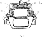
- Figs. 1 - 3 show schematically an adjustment structure in a vehicle front lamp according to the present invention.
- the adjustment structure comprises at least one adjustable optical part 100, a fixing part 200 and multiple connecting parts 300.
- the fixing part 200 is used for connection with a vehicle frame; the adjustable optical part 100 is connected to the vehicle via the fixing part 200.
- An optical structure 400 is used in the adjustable optical part 100 for implementation.
- the adjustable optical part 100 comprises the optical structure 400, and an optical support member 120 for supporting the optical structure 400.
- a first threaded hole 110 of the adjustable optical part 100 is located on the optical support member 120.
- the optical structure 400 comprises optical components for adjusting a beam pattern of a light beam, and combinations thereof.
- the optical structure 400 comprises at least any one of the following optical components:
- the optical structure 400 may comprise any one of the following:
- the fixing part 200 comprises but is not limited to a light source part 220 and a support structure 230.
- the light source part 220 comprises an LED light source. More preferably, the light source part 220 comprises the light source itself and a PCB to which it belongs.
- the support structure 230 comprises but is not limited to a bearing structure for bearing the PCB on which the light source is located. More preferably, the support structure 230 further comprises a heat dissipating structure (heat sink) that is integral with the PCB and itself.
- heat sink heat dissipating structure
- a second threaded hole 210 of the fixing part 200 is located on the support structure 230.
- the fixing part 200 further comprises at least one optical structure 400.
- the adjustable optical part 100 comprises the low beam part 400a
- the fixing part 200 comprises the light source part 220, the support structure 230 and the high beam part 400b.
- the adjustable optical part 100 comprises multiple first threaded holes 110; the fixing part 200 comprises multiple second threaded holes 210 respectively corresponding to the multiple first threaded holes 110 of at least one adjustable optical part 100.
- the multiple connecting parts 300 are configured to pass through each of the first threaded holes 110 and each of the second threaded holes 210 respectively corresponding thereto, in order to connect the at least one adjustable optical part 100 and the fixing part 200.
- the first threaded hole 110 and the second threaded hole 210 have different hole diameters.
- the hole diameter of the first threaded hole 110 is smaller than the hole diameter of the second threaded hole 210, or the hole diameters of the first threaded hole 110 are all larger than the hole diameter of the second threaded hole 210.
- respective central axes of the multiple first threaded holes 110 and multiple second threaded holes 210 may not be coincident.
- the adjustable optical part 100 may first be moved along x and y axes along a plane of the multiple second threaded holes 210, in order to adjust a beam pattern, and when the beam pattern meets requirements, relative positions of the first threaded holes 110 of the adjustable optical part 100 and the second threaded holes 210 of the fixing part 200 may be fixed by the connecting parts 300.
- the optical part and the fixing part are thereby connected and fixed, in order to obtain the abovementioned beam pattern.
- the central axes of the two threaded holes may be coincident, i.e. the first threaded hole 110 and the second threaded hole 210 are centre-aligned; or may not be coincident, i.e. the first threaded hole 110 and the second threaded hole 210 are not centre-aligned.
- the connecting part 300 is configured to pass through the first threaded hole 110 and the second threaded hole 210, in order to fix the adjustable optical part 100 and the fixing part 200.
- the connecting part 300 comprises a screw structure 310 and a nut structure 320.
- the screw structure 310 is configured to pass through the first threaded hole 110 and the second threaded hole 210 in order to connect the at least one adjustable optical part 100 and the fixing part 200; the nut structure 320 is used to lock the screw structure 310 at another side of the adjustable optical part 100 and the fixing part 200 passed through by the screw structure 310.
- the screw structure 310 comprises a screw rod part 311 and a screw tail part 312.
- the hole diameter of the first threaded hole 110 is denoted as D1
- the hole diameter of the second threaded hole 210 is denoted as D2
- the width of the screw tail part 312 is denoted as dw1
- the width of the nut structure is denoted as dw2.
- the screw rod part 311 has a rod part main body and a screw-thread structure, wherein the diameter of a rod part structure is denoted as d1, and the diameter of the screw-thread structure is denoted as d2.
- the interior of the nut structure 320 has a first hole diameter d1' corresponding to the rod part structure, and a hole diameter d2' corresponding to the screw-thread structure.
- the screw tail part 312 has a certain width dw1, and the width dw1 thereof is greater than at least one of the hole diameter D1 of the first threaded hole 110 and the hole diameter D2 of the second threaded hole 210.
- the screw tail part 312 when installation is performed, the screw tail part 312 is positioned at one side of the threaded hole with the smaller hole diameter, such that the screw rod part 311 passes through the threaded hole with the smaller hole diameter and the threaded hole with the larger hole diameter in sequence, and is then locked by the nut structure 320.
- the width dw1 of the screw tail part 312 is greater than the hole diameter D1 of the first threaded hole 110 and the hole diameter D2 of the second threaded hole 210 respectively.
- the width of the screw tail part 312 is greater than the hole diameters of both the first threaded hole 110 and the second threaded hole 210.
- the screw tail part 312 may be at either side of the first threaded hole 110 or the second threaded hole 210.
- the nut width dw2 of the nut structure 320 is greater than the hole diameter D1 of the first threaded hole 110 and the hole diameter D2 of the second threaded hole 210 respectively.
- the connecting part 300 may employ a standard screw structure 310 and a standard nut structure 320.
- An example is a screw nut structure with the specification 4 x 12 (the screw rod part 311 being of length 12 mm, with a screw-thread diameter of 4 mm), or a screw nut structure with the specification 4 x 14 (the screw rod part 311 being of length 14 mm, with a screw-thread diameter of 4 mm), etc.; production costs can thereby be lowered further.
- Those skilled in the art should be able to determine the required specifications according to actual circumstances and demands, with no restriction to the examples given above.
- At least one adjustable optical part 100 thereof comprises the low beam part 400a; the fixing part 200 comprises the light source part 220, the support structure 230 and the high beam part 400b.
- the low beam part 400a comprises multiple first threaded holes 110
- the fixing part 200 comprises multiple second threaded holes 210; by adjusting the relative positions of the first threaded holes 110 of the low beam part 400a and the second threaded holes 210, in order to adjust the relative positions of the low beam part 400a and the high beam part 400b contained in the fixing part 200, the required beam pattern is obtained, then multiple corresponding connecting parts 300 are used to fix the relative positions of the first threaded holes 110 and the second threaded holes 210 respectively, in order to secure the beam pattern.
- the number of parts which need to be used is reduced, and the number of dimensions in which adjustment is possible is increased (expanded to two dimensions, specifically x and y); moreover, the adjustment process is simplified. Furthermore, in the case where standard parts are used, the cost of beam pattern adjustment can be further reduced.
Landscapes
- Engineering & Computer Science (AREA)
- General Engineering & Computer Science (AREA)
- Physics & Mathematics (AREA)
- Microelectronics & Electronic Packaging (AREA)
- Optics & Photonics (AREA)
- Lighting Device Outwards From Vehicle And Optical Signal (AREA)
- Non-Portable Lighting Devices Or Systems Thereof (AREA)
Abstract
Description
- The present invention relates to the technical field of vehicle lamps, in particular to an adjustment structure in a vehicle lamp, a vehicle lamp and a corresponding vehicle.
- When a motor vehicle front lamp is installed on a complete vehicle, it is also necessary to make slight adjustments to lamp components, so that they fully satisfy legal requirements. Currently, when vehicle lamp installation is complete, i.e. when all optical components have been fixed, components such as a centring ring and an adjusting screw are generally used to move a light source, and thereby adjust a beam pattern of actual emergent light.
- However, such a solution requires a large number of components, and furthermore, moving the light source means moving an entire support on which the light source is located; the component moved is large, and the operation is complex. Moreover, in such a solution, it is often only possible to perform adjustment in one direction, so flexibility is lacking.
- In view of the above, one problem solved by an embodiment of the present invention is how to simplify an adjustment operation and increase adjustment direction flexibility.
- According to one aspect of the present invention, an adjustment structure of a lamp is disclosed, wherein the adjustment structure comprises:
- at least one adjustable optical part;
- a fixing part;
- multiple connecting parts,
- wherein the adjustable optical part comprises multiple first threaded holes, and the fixing part comprises multiple second threaded holes respectively corresponding to the multiple first threaded holes of at least one optical part; the multiple connecting parts are configured to pass through each of the first threaded holes and each of the second threaded holes respectively corresponding thereto, in order to connect the at least one optical part and the fixing part.
- According to the solution of the present invention, the use of the connecting parts to connect the optical part and the fixing part makes the connection structure simpler.
- In the adjustment structure according to the present invention, the first threaded hole and the second threaded hole have different hole diameters.
- According to the solution of the present invention, using the difference between the hole diameters of the first threaded hole and the second threaded hole, the position of the adjustable optical part relative to the fixing part can be subjected to a certain amount of adjustment, so as to obtain a beam pattern which is fully compliant with regulations.
- In the adjustment structure according to the present invention, when the connecting parts connect the at least one adjustable optical part and the fixing part, respective central axes of the multiple first threaded holes and multiple second threaded holes may not be coincident.
- According to the solution of the present invention, after shifting the adjustable optical part slightly relative to the fixing part, the adjustable optical part and the fixing part can be connected without the respective central axes of the first threaded holes and the second threaded holes being coincident, i.e. the installation thereof is made flexible to a certain degree.
- In the adjustment structure according to the present invention, the connecting part further comprises:
- a screw structure, configured to pass through the first threaded hole and the second threaded hole in order to connect the at least one optical part and the fixing part;
- a nut structure, used to lock the screw structure.
- According to the solution of the present invention, the method of mating screws with nuts is used to realize the connection of the optical part and the fixing part, simplifying the structure of the connecting part and reducing the number of components which need to be used.
- In the adjustment structure according to the present invention, the screw structure further comprises:
- a screw rod part;
- a screw tail part, wherein the width of the screw tail part is greater than the hole diameter of at least one of the first threaded hole and the second threaded hole.
- According to the solution of the present invention, the fact that the width of the screw tail part is greater than at least one hole diameter can effectively ensure the stability of connection and fixing.
- In the adjustment structure according to the present invention, the width of the screw tail part is greater than the hole diameters of the first threaded hole and the second threaded hole respectively.
- According to the solution of the present invention, the fact that the width of the screw tail part is greater than at least one hole diameter can effectively ensure the stability of connection and fixing.
- In the adjustment structure according to the present invention, the nut width of the nut structure is greater than the hole diameters of the first threaded hole and the second threaded hole respectively.
- According to the solution of the present invention, when the width of the screw tail part is greater than the hole diameters of the two threaded holes, there is no need to take into account the installation direction of the screw, so the installation thereof is simpler and more convenient.
- In the adjustment structure according to the present invention, each of the at least one adjustable optical part is realized by an optical structure.
- According to the solution of the present invention, beam pattern adjustment is realized by adjusting the optical structure, so operation is simpler and more convenient.
- In the adjustment structure according to the present invention, the fixing part comprises a light source and a corresponding support structure.
- According to the solution of the present invention, in the adjustment structure, only the position of the adjustable optical part is adjusted, with no need to move the support structure and the light source, hence the structure that is actually adjusted is smaller, and the manner of adjustment is simpler.
- In the adjustment structure according to the present invention, the fixing part further comprises one or more optical structures.
- According to the solution of the present invention, the fixing part may further comprise a portion of the optical part, thereby minimizing the size of the component that needs to be moved, for greater simplicity and convenience.
- In the adjustment structure according to the present invention, the optical structure comprises any one of the following:
- a low beam part;
- a high beam part.
- In the adjustment structure according to the present invention, the at least one adjustable optical part comprises the low beam part, and the fixing part comprises the light source, the support structure and the high beam part.
- According to one aspect of the present invention, a vehicle lamp is disclosed, wherein the vehicle lamp comprises the adjustment structure.
- In the vehicle lamp according to the present invention, the vehicle lamp is a front lamp.
- According to one aspect of the present invention, a vehicle is disclosed, wherein the vehicle comprises the vehicle lamp.
- Compared with the prior art, the present invention has the following advantages: adjustment is realized by moving an optical component; compared with the method of moving the entire support structure and light source in the prior art, it is more convenient to move the optical component in the present invention, fewer components need to be used, and costs can be reduced. Furthermore, the movement thereof is realized on the basis of the difference in hole diameter between the threaded holes, therefore it can move in at least two dimensions; compared with the prior art, the number of dimensions in which movement is possible is increased, and the adjustment thereof is more flexible.
- Other features, objects and advantages of the present invention will become more obvious through perusal of a detailed description of non-limiting embodiments which makes reference to the accompanying drawings below:
-
Fig. 1 shows a structural schematic drawing corresponding to a front view of a motor vehicle front lamp according to an embodiment of the present invention. -
Fig. 2 shows a structural schematic drawing corresponding to a rear view of a motor vehicle front lamp according to an embodiment of the present invention. -
Fig. 3 shows a three-dimensional structural schematic drawing of a motor vehicle front lamp according to an embodiment of the present invention. -
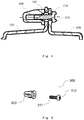
Fig. 4 shows a sectional schematic drawing of an adjustment structure according to an embodiment of the present invention. -
Fig. 5 shows a structural schematic drawing of a connecting part of an adjustment structure according to an embodiment of the present invention. -
Fig. 6 shows an exploded schematic drawing of an adjustment structure according to an embodiment of the present invention, viewed at one angle in three dimensions. -
Fig. 7 shows an exploded schematic drawing of an optical part and a fixing part of an adjustment structure according to an embodiment of the present invention, viewed at another angle in three dimensions. -
Figs. 8a, 8b, 8c and 8d show schematic drawings of the sizes of a first threaded hole, a second threaded hole, a nut structure and a screw structure according to an embodiment of the present invention. - Preferred embodiments of the present invention are described in greater detail below with reference to the accompanying drawings. Although preferred embodiments of the present invention are shown in the drawings, it should be understood that the present invention may be realized in various forms, and should not be restricted by the embodiments expounded here. On the contrary, these embodiments are provided in order to make the present invention more thorough and complete, and to enable the scope of the present invention to be conveyed to those skilled in the art in a complete fashion.
- According to embodiments of the present invention, an adjustment structure in a vehicle lamp, a vehicle lamp and a corresponding vehicle are disclosed. Preferably, the vehicle lamp is a front lamp of a vehicle.
- Referring to
Figs. 1 - 3, Figs. 1 - 3 show schematically an adjustment structure in a vehicle front lamp according to the present invention. The adjustment structure comprises at least one adjustableoptical part 100, afixing part 200 and multiple connectingparts 300. - The fixing
part 200 is used for connection with a vehicle frame; the adjustableoptical part 100 is connected to the vehicle via the fixingpart 200. - An optical structure 400 is used in the adjustable
optical part 100 for implementation. Preferably, the adjustableoptical part 100 comprises the optical structure 400, and anoptical support member 120 for supporting the optical structure 400. - More preferably, a first threaded
hole 110 of the adjustableoptical part 100 is located on theoptical support member 120. - Preferably, the optical structure 400 comprises optical components for adjusting a beam pattern of a light beam, and combinations thereof.
- Preferably, the optical structure 400 comprises at least any one of the following optical components:
- 1) a lens structure;
- 2) a light guide structure;
- 3) a shading structure;
- 4) a reflecting structure, etc.
- According to the solution of the present invention, when the adjustment structure is used for a vehicle front lamp, the optical structure 400 may comprise any one of the following:
- 1) a
low beam part 400a; thelow beam part 400a is used to realize a low beam pattern in the vehicle front lamp; - 2) a
high beam part 400b; thehigh beam part 400b is used to realize a high beam pattern in the vehicle front lamp, independently or through cooperation with the low beam part. - The fixing
part 200 comprises but is not limited to a light source part 220 and asupport structure 230. - Preferably, the light source part 220 comprises an LED light source. More preferably, the light source part 220 comprises the light source itself and a PCB to which it belongs.
- Preferably, the
support structure 230 comprises but is not limited to a bearing structure for bearing the PCB on which the light source is located. More preferably, thesupport structure 230 further comprises a heat dissipating structure (heat sink) that is integral with the PCB and itself. - More preferably, a second threaded
hole 210 of the fixingpart 200 is located on thesupport structure 230. - According to a preferred solution of the present invention, the fixing
part 200 further comprises at least one optical structure 400. - For example, the adjustable
optical part 100 comprises thelow beam part 400a, and the fixingpart 200 comprises the light source part 220, thesupport structure 230 and thehigh beam part 400b. - The adjustable
optical part 100 comprises multiple first threadedholes 110; the fixingpart 200 comprises multiple second threadedholes 210 respectively corresponding to the multiple first threadedholes 110 of at least one adjustableoptical part 100. The multiple connectingparts 300 are configured to pass through each of the first threadedholes 110 and each of the second threadedholes 210 respectively corresponding thereto, in order to connect the at least one adjustableoptical part 100 and the fixingpart 200. - Preferably, the first threaded
hole 110 and the second threadedhole 210 have different hole diameters. - Specifically, the hole diameter of the first threaded
hole 110 is smaller than the hole diameter of the second threadedhole 210, or the hole diameters of the first threadedhole 110 are all larger than the hole diameter of the second threadedhole 210. - More preferably, when the connecting
parts 300 connect the at least one adjustableoptical part 100 and the fixingpart 200, respective central axes of the multiple first threadedholes 110 and multiple second threadedholes 210 may not be coincident. - Specifically, using first threaded
holes 110 and second threadedholes 210 of different hole diameters, before using the connectingpart 300 to fix the adjustableoptical part 100 and the fixingpart 200, the adjustableoptical part 100 may first be moved along x and y axes along a plane of the multiple second threadedholes 210, in order to adjust a beam pattern, and when the beam pattern meets requirements, relative positions of the first threadedholes 110 of the adjustableoptical part 100 and the second threadedholes 210 of the fixingpart 200 may be fixed by the connectingparts 300. The optical part and the fixing part are thereby connected and fixed, in order to obtain the abovementioned beam pattern. - As will be understandable to those skilled in the art, when the required beam pattern is obtained, the central axes of the two threaded holes may be coincident, i.e. the first threaded
hole 110 and the second threadedhole 210 are centre-aligned; or may not be coincident, i.e. the first threadedhole 110 and the second threadedhole 210 are not centre-aligned. - Next, referring to
figs. 4 and 5 , the connectingpart 300 is configured to pass through the first threadedhole 110 and the second threadedhole 210, in order to fix the adjustableoptical part 100 and the fixingpart 200. - Preferably, the connecting
part 300 comprises ascrew structure 310 and anut structure 320. - The
screw structure 310 is configured to pass through the first threadedhole 110 and the second threadedhole 210 in order to connect the at least one adjustableoptical part 100 and the fixingpart 200; thenut structure 320 is used to lock thescrew structure 310 at another side of the adjustableoptical part 100 and the fixingpart 200 passed through by thescrew structure 310. - According to a preferred solution of this embodiment, the
screw structure 310 comprises ascrew rod part 311 and ascrew tail part 312. - Referring to
figs. 8a, 8b, 8c and 8d , in which the hole diameter of the first threadedhole 110 is denoted as D1, the hole diameter of the second threadedhole 210 is denoted as D2, the width of thescrew tail part 312 is denoted as dw1, and the width of the nut structure is denoted as dw2. - Preferably, the
screw rod part 311 has a rod part main body and a screw-thread structure, wherein the diameter of a rod part structure is denoted as d1, and the diameter of the screw-thread structure is denoted as d2. Correspondingly, the interior of thenut structure 320 has a first hole diameter d1' corresponding to the rod part structure, and a hole diameter d2' corresponding to the screw-thread structure. - The
screw tail part 312 has a certain width dw1, and the width dw1 thereof is greater than at least one of the hole diameter D1 of the first threadedhole 110 and the hole diameter D2 of the second threadedhole 210. - Specifically, when installation is performed, the
screw tail part 312 is positioned at one side of the threaded hole with the smaller hole diameter, such that thescrew rod part 311 passes through the threaded hole with the smaller hole diameter and the threaded hole with the larger hole diameter in sequence, and is then locked by thenut structure 320. - Preferably, the width dw1 of the
screw tail part 312 is greater than the hole diameter D1 of the first threadedhole 110 and the hole diameter D2 of the second threadedhole 210 respectively. - That is, the width of the
screw tail part 312 is greater than the hole diameters of both the first threadedhole 110 and the second threadedhole 210. - At this time, the
screw tail part 312 may be at either side of the first threadedhole 110 or the second threadedhole 210. - According to another preferred solution of this embodiment, the nut width dw2 of the
nut structure 320 is greater than the hole diameter D1 of the first threadedhole 110 and the hole diameter D2 of the second threadedhole 210 respectively. - As should be understandable to those skilled in the art, when the first threaded
hole 110 or the second threadedhole 210 employs a standard hole diameter, the connectingpart 300 may employ astandard screw structure 310 and astandard nut structure 320. - An example is a screw nut structure with the specification 4 x 12 (the
screw rod part 311 being of length 12 mm, with a screw-thread diameter of 4 mm), or a screw nut structure with the specification 4 x 14 (thescrew rod part 311 being of length 14 mm, with a screw-thread diameter of 4 mm), etc.; production costs can thereby be lowered further. Those skilled in the art should be able to determine the required specifications according to actual circumstances and demands, with no restriction to the examples given above. - Preferably, according to one embodiment of the present invention, reference is made to
figs. 6 and7 . In the adjustment structure for a motor vehicle front lamp, at least one adjustableoptical part 100 thereof comprises thelow beam part 400a; the fixingpart 200 comprises the light source part 220, thesupport structure 230 and thehigh beam part 400b. - That is, the
low beam part 400a comprises multiple first threadedholes 110, and the fixingpart 200 comprises multiple second threadedholes 210; by adjusting the relative positions of the first threadedholes 110 of thelow beam part 400a and the second threadedholes 210, in order to adjust the relative positions of thelow beam part 400a and thehigh beam part 400b contained in the fixingpart 200, the required beam pattern is obtained, then multiple corresponding connectingparts 300 are used to fix the relative positions of the first threadedholes 110 and the second threadedholes 210 respectively, in order to secure the beam pattern. - According to the solution of the present invention, through the use of the adjustment structure described above, the number of parts which need to be used is reduced, and the number of dimensions in which adjustment is possible is increased (expanded to two dimensions, specifically x and y); moreover, the adjustment process is simplified. Furthermore, in the case where standard parts are used, the cost of beam pattern adjustment can be further reduced.
- To a person skilled in the art, it is obvious that the present invention is not limited to the details of the demonstrative embodiments above, and could be implemented in other specific forms without deviating from the spirit or fundamental features of the present invention. Thus, regardless of which viewpoint is taken, the embodiments should be regarded as being demonstrative and non-limiting; the scope of the present invention is defined by the attached claims and not by the explanation above, hence it is intended that all changes falling within the meaning and scope of equivalent key elements of the claims be included in the present invention. No reference labels in the claims should be regarded as limiting the claims concerned. In addition, it is obvious that the word "comprises" does not exclude other units or steps, and the singular does not exclude the plural. Multiple units or apparatuses presented in system claims may also be realized by one unit or apparatus by means of software or hardware. Words such as first and second are used to indicate designations, and do not indicate any specific order.
| 100 | | 200 | |
| 300 | connecting | 110 | first threaded |
| 210 | second threaded hole | 220 | |
| 230 | | 310 | |
| 320 | | 311 | |
| 312 | screw tail part | 400 | |
| 400b | | 400a | low beam part |
Claims (15)
- An adjustment structure in a vehicle lamp, wherein the adjustment structure comprises:at least one adjustable optical part (100);a fixing part (200);multiple connecting parts (300);wherein the adjustable optical part (100) comprises multiple first threaded holes (110), and the fixing part (200) comprises multiple second threaded holes (210) respectively corresponding to the multiple first threaded holes (110) of at least one adjustable optical part (100);the multiple connecting parts (300) are configured to pass through each of the first threaded holes (110) and each of the second threaded holes (210) respectively corresponding thereto, to connect the at least one optical part (100) and the fixing part (200).
- The adjustment structure according to Claim 1, wherein the first threaded hole (110) and the second threaded hole (210) have different hole diameters.
- The adjustment structure according to Claim 2, wherein when the connecting parts (300) connect the at least one adjustable optical part (100) and the fixing part (200), respective central axes of the multiple first threaded holes (110) and multiple second threaded holes (210) are offset with each other.
- The adjustment structure according to any of Claims 1 - 3, wherein the connecting part (300) further comprises:a screw structure (310), configured to pass through the first threaded hole (110) and the second threaded hole (210) to connect the at least one adjustable optical part (100) and the fixing part (200);a nut structure (320), used to lock the screw structure (310) at another side of the adjustable optical part (100) and the fixing part (200) passed through by the screw structure (310).
- The adjustment structure according to Claim 4, wherein the screw structure (310) further comprises:a screw rod part (311);a screw tail part (312), wherein the width of the screw tail part (312) is greater than the hole diameter of at least one of the first threaded hole (110) and the second threaded hole (210).
- The adjustment structure according to Claim 5, wherein the width of the screw tail part (312) is greater than the hole diameters of the first threaded hole (110) and the second threaded hole (210) respectively.
- The adjustment structure according to any one of Claims 4 - 6, wherein the nut width of the nut structure (320) is greater than the hole diameters of the first threaded hole (110) and the second threaded hole (210) respectively.
- The adjustment structure according to any of Claims 1 - 3, wherein each of the at least one adjustable optical part (100) is realized by an optical structure (400).
- The adjustment structure according to any of Claims 1 - 3, wherein the fixing part (200) comprises a light source part (220) and a corresponding support structure (230).
- The adjustment structure according to Claim 9, wherein the fixing part (200) further comprises one or more optical structures (400).
- The adjustment structure according to any one of Claims 8 - 10, wherein the optical structure (400) comprises any of the following:- a low beam part (400a); and- a high beam part (400b).
- The adjustment structure according to Claim 11, wherein the at least one adjustable optical part (100) comprises the low beam part (400a), and the fixing part (200) comprises the light source part (220), the support structure (230) and the high beam part (400b).
- An Vehicle lamp, wherein the vehicle lamp comprises the adjustment structure according to any of Claims 1 - 12.
- The vehicle lamp according to Claim 13, wherein the vehicle lamp is a front lamp.
- A vehicle, wherein the vehicle comprises the vehicle lamp according to Claim 13 or 14.
Applications Claiming Priority (1)
| Application Number | Priority Date | Filing Date | Title |
|---|---|---|---|
| CN201920545127.XU CN211289919U (en) | 2019-04-19 | 2019-04-19 | Adjustment structure in a vehicle lamp, vehicle lamp and corresponding vehicle |
Publications (1)
| Publication Number | Publication Date |
|---|---|
| EP3730835A1 true EP3730835A1 (en) | 2020-10-28 |
Family
ID=70294954
Family Applications (1)
| Application Number | Title | Priority Date | Filing Date |
|---|---|---|---|
| EP20169952.7A Withdrawn EP3730835A1 (en) | 2019-04-19 | 2020-04-16 | Adjustment structure in vehicle lamp, vehicle lamp and corresponding vehicle |
Country Status (2)
| Country | Link |
|---|---|
| EP (1) | EP3730835A1 (en) |
| CN (1) | CN211289919U (en) |
Citations (4)
| Publication number | Priority date | Publication date | Assignee | Title |
|---|---|---|---|---|
| US20160320012A1 (en) * | 2014-01-22 | 2016-11-03 | Koito Manufacturing Co., Ltd. | Vehicle lamp |
| FR3056698A1 (en) * | 2016-09-26 | 2018-03-30 | Valeo Vision | LUMINOUS MODULE FOR MOTOR VEHICLE |
| FR3062460A1 (en) * | 2017-02-01 | 2018-08-03 | Valeo Vision | LUMINOUS MODULE FOR VEHICLE PROJECTOR |
| US20180292064A1 (en) * | 2017-04-11 | 2018-10-11 | Valeo Lighting Hubei Technical Center Co. Ltd | Lighting apparatus and automobile vehicle |
-
2019
- 2019-04-19 CN CN201920545127.XU patent/CN211289919U/en active Active
-
2020
- 2020-04-16 EP EP20169952.7A patent/EP3730835A1/en not_active Withdrawn
Patent Citations (4)
| Publication number | Priority date | Publication date | Assignee | Title |
|---|---|---|---|---|
| US20160320012A1 (en) * | 2014-01-22 | 2016-11-03 | Koito Manufacturing Co., Ltd. | Vehicle lamp |
| FR3056698A1 (en) * | 2016-09-26 | 2018-03-30 | Valeo Vision | LUMINOUS MODULE FOR MOTOR VEHICLE |
| FR3062460A1 (en) * | 2017-02-01 | 2018-08-03 | Valeo Vision | LUMINOUS MODULE FOR VEHICLE PROJECTOR |
| US20180292064A1 (en) * | 2017-04-11 | 2018-10-11 | Valeo Lighting Hubei Technical Center Co. Ltd | Lighting apparatus and automobile vehicle |
Also Published As
| Publication number | Publication date |
|---|---|
| CN211289919U (en) | 2020-08-18 |
Similar Documents
| Publication | Publication Date | Title |
|---|---|---|
| EP4027052A1 (en) | Optical element of vehicle light | |
| US5528714A (en) | Fiber optics light source with adjustable mounting, replaceable color wheel elements and cooling | |
| WO2002084339A3 (en) | Projection display system using two lamp sources | |
| JP2009289751A (en) | Rear-mounted light emitting diode module for automobile rear combination lamp | |
| CN112804503B (en) | Integrated Illumination - Sight Imaging Unit | |
| EP4123216A1 (en) | Dimming mechanism, vehicle lamp module, vehicle lamp, and vehicle | |
| JP2008128995A (en) | Vehicular radar system, and manufacturing method therefor | |
| EP3457024B1 (en) | Motor vehicle headlamp for transmitting a long distance light distribution pattern | |
| CA2160598C (en) | Lamp reflector | |
| EP2588800B1 (en) | Lighting module for an outdoor light | |
| US20030012028A1 (en) | Headlight, especially for a motor vehicle, and method for adjusting light radiated by the headlight | |
| EP4204733B1 (en) | Motor vehicle headlamp | |
| EP3879171A1 (en) | Collimator, lighting structure, vehicle lamp and corresponding vehicle | |
| CN108302461A (en) | Illumination and/or signal indicating device for motor vehicle and the component for including multiple devices | |
| US11725794B2 (en) | Reduced-tolerance lighting device for vehicles | |
| CN211289919U (en) | Adjustment structure in a vehicle lamp, vehicle lamp and corresponding vehicle | |
| CN106949421A (en) | A kind of LED automobile lamp with detachable reflector | |
| WO2020229432A1 (en) | Optical structure, corresponding vehicle lamp and vehicle | |
| EP3680548A1 (en) | Reflector unit | |
| CN119270516A (en) | Optical systems and optical equipment | |
| CN210345325U (en) | Car light lighting device, vehicle headlamp and vehicle | |
| CN223796821U (en) | Light path correcting device | |
| CN220728084U (en) | Optical lighting device and optical equipment | |
| CN221497997U (en) | Periscope type projection lamp assembly for rail transit train | |
| CN110500554B (en) | Hinge, installation governing system, car light module unit, base and car light |
Legal Events
| Date | Code | Title | Description |
|---|---|---|---|
| PUAI | Public reference made under article 153(3) epc to a published international application that has entered the european phase |
Free format text: ORIGINAL CODE: 0009012 |
|
| STAA | Information on the status of an ep patent application or granted ep patent |
Free format text: STATUS: THE APPLICATION HAS BEEN PUBLISHED |
|
| AK | Designated contracting states |
Kind code of ref document: A1 Designated state(s): AL AT BE BG CH CY CZ DE DK EE ES FI FR GB GR HR HU IE IS IT LI LT LU LV MC MK MT NL NO PL PT RO RS SE SI SK SM TR |
|
| AX | Request for extension of the european patent |
Extension state: BA ME |
|
| STAA | Information on the status of an ep patent application or granted ep patent |
Free format text: STATUS: REQUEST FOR EXAMINATION WAS MADE |
|
| 17P | Request for examination filed |
Effective date: 20210427 |
|
| RBV | Designated contracting states (corrected) |
Designated state(s): AL AT BE BG CH CY CZ DE DK EE ES FI FR GB GR HR HU IE IS IT LI LT LU LV MC MK MT NL NO PL PT RO RS SE SI SK SM TR |
|
| STAA | Information on the status of an ep patent application or granted ep patent |
Free format text: STATUS: EXAMINATION IS IN PROGRESS |
|
| 17Q | First examination report despatched |
Effective date: 20220811 |
|
| P01 | Opt-out of the competence of the unified patent court (upc) registered |
Effective date: 20230528 |
|
| STAA | Information on the status of an ep patent application or granted ep patent |
Free format text: STATUS: THE APPLICATION IS DEEMED TO BE WITHDRAWN |
|
| 18D | Application deemed to be withdrawn |
Effective date: 20241101 |