EP3730810B1 - Plunging assembly of drive shaft - Google Patents
Plunging assembly of drive shaft Download PDFInfo
- Publication number
- EP3730810B1 EP3730810B1 EP19741163.0A EP19741163A EP3730810B1 EP 3730810 B1 EP3730810 B1 EP 3730810B1 EP 19741163 A EP19741163 A EP 19741163A EP 3730810 B1 EP3730810 B1 EP 3730810B1
- Authority
- EP
- European Patent Office
- Prior art keywords
- outer housing
- bore
- inner shaft
- plunging
- mounting hole
- Prior art date
- Legal status (The legal status is an assumption and is not a legal conclusion. Google has not performed a legal analysis and makes no representation as to the accuracy of the status listed.)
- Active
Links
Images



Classifications
-
- F—MECHANICAL ENGINEERING; LIGHTING; HEATING; WEAPONS; BLASTING
- F16—ENGINEERING ELEMENTS AND UNITS; GENERAL MEASURES FOR PRODUCING AND MAINTAINING EFFECTIVE FUNCTIONING OF MACHINES OR INSTALLATIONS; THERMAL INSULATION IN GENERAL
- F16D—COUPLINGS FOR TRANSMITTING ROTATION; CLUTCHES; BRAKES
- F16D3/00—Yielding couplings, i.e. with means permitting movement between the connected parts during the drive
- F16D3/16—Universal joints in which flexibility is produced by means of pivots or sliding or rolling connecting parts
- F16D3/20—Universal joints in which flexibility is produced by means of pivots or sliding or rolling connecting parts one coupling part entering a sleeve of the other coupling part and connected thereto by sliding or rolling members
- F16D3/22—Universal joints in which flexibility is produced by means of pivots or sliding or rolling connecting parts one coupling part entering a sleeve of the other coupling part and connected thereto by sliding or rolling members the rolling members being balls, rollers, or the like, guided in grooves or sockets in both coupling parts
- F16D3/223—Universal joints in which flexibility is produced by means of pivots or sliding or rolling connecting parts one coupling part entering a sleeve of the other coupling part and connected thereto by sliding or rolling members the rolling members being balls, rollers, or the like, guided in grooves or sockets in both coupling parts the rolling members being guided in grooves in both coupling parts
-
- F—MECHANICAL ENGINEERING; LIGHTING; HEATING; WEAPONS; BLASTING
- F16—ENGINEERING ELEMENTS AND UNITS; GENERAL MEASURES FOR PRODUCING AND MAINTAINING EFFECTIVE FUNCTIONING OF MACHINES OR INSTALLATIONS; THERMAL INSULATION IN GENERAL
- F16C—SHAFTS; FLEXIBLE SHAFTS; ELEMENTS OR CRANKSHAFT MECHANISMS; ROTARY BODIES OTHER THAN GEARING ELEMENTS; BEARINGS
- F16C3/00—Shafts; Axles; Cranks; Eccentrics
- F16C3/02—Shafts; Axles
- F16C3/03—Shafts; Axles telescopic
- F16C3/035—Shafts; Axles telescopic with built-in bearings
-
- B—PERFORMING OPERATIONS; TRANSPORTING
- B60—VEHICLES IN GENERAL
- B60B—VEHICLE WHEELS; CASTORS; AXLES FOR WHEELS OR CASTORS; INCREASING WHEEL ADHESION
- B60B35/00—Axle units; Parts thereof ; Arrangements for lubrication of axles
- B60B35/12—Torque-transmitting axles
-
- B—PERFORMING OPERATIONS; TRANSPORTING
- B60—VEHICLES IN GENERAL
- B60B—VEHICLE WHEELS; CASTORS; AXLES FOR WHEELS OR CASTORS; INCREASING WHEEL ADHESION
- B60B35/00—Axle units; Parts thereof ; Arrangements for lubrication of axles
- B60B35/12—Torque-transmitting axles
- B60B35/121—Power-transmission from drive shaft to hub
- B60B35/127—Power-transmission from drive shaft to hub using universal joints
- B60B35/128—Power-transmission from drive shaft to hub using universal joints of the homokinetic or constant velocity type
-
- B—PERFORMING OPERATIONS; TRANSPORTING
- B60—VEHICLES IN GENERAL
- B60B—VEHICLE WHEELS; CASTORS; AXLES FOR WHEELS OR CASTORS; INCREASING WHEEL ADHESION
- B60B35/00—Axle units; Parts thereof ; Arrangements for lubrication of axles
- B60B35/12—Torque-transmitting axles
- B60B35/14—Torque-transmitting axles composite or split, e.g. half- axles; Couplings between axle parts or sections
-
- B—PERFORMING OPERATIONS; TRANSPORTING
- B60—VEHICLES IN GENERAL
- B60B—VEHICLE WHEELS; CASTORS; AXLES FOR WHEELS OR CASTORS; INCREASING WHEEL ADHESION
- B60B35/00—Axle units; Parts thereof ; Arrangements for lubrication of axles
- B60B35/12—Torque-transmitting axles
- B60B35/18—Arrangement of bearings
-
- F—MECHANICAL ENGINEERING; LIGHTING; HEATING; WEAPONS; BLASTING
- F16—ENGINEERING ELEMENTS AND UNITS; GENERAL MEASURES FOR PRODUCING AND MAINTAINING EFFECTIVE FUNCTIONING OF MACHINES OR INSTALLATIONS; THERMAL INSULATION IN GENERAL
- F16D—COUPLINGS FOR TRANSMITTING ROTATION; CLUTCHES; BRAKES
- F16D3/00—Yielding couplings, i.e. with means permitting movement between the connected parts during the drive
- F16D3/02—Yielding couplings, i.e. with means permitting movement between the connected parts during the drive adapted to specific functions
- F16D3/06—Yielding couplings, i.e. with means permitting movement between the connected parts during the drive adapted to specific functions specially adapted to allow axial displacement
- F16D3/065—Yielding couplings, i.e. with means permitting movement between the connected parts during the drive adapted to specific functions specially adapted to allow axial displacement by means of rolling elements
-
- F—MECHANICAL ENGINEERING; LIGHTING; HEATING; WEAPONS; BLASTING
- F16—ENGINEERING ELEMENTS AND UNITS; GENERAL MEASURES FOR PRODUCING AND MAINTAINING EFFECTIVE FUNCTIONING OF MACHINES OR INSTALLATIONS; THERMAL INSULATION IN GENERAL
- F16C—SHAFTS; FLEXIBLE SHAFTS; ELEMENTS OR CRANKSHAFT MECHANISMS; ROTARY BODIES OTHER THAN GEARING ELEMENTS; BEARINGS
- F16C2326/00—Articles relating to transporting
- F16C2326/01—Parts of vehicles in general
- F16C2326/06—Drive shafts
-
- F—MECHANICAL ENGINEERING; LIGHTING; HEATING; WEAPONS; BLASTING
- F16—ENGINEERING ELEMENTS AND UNITS; GENERAL MEASURES FOR PRODUCING AND MAINTAINING EFFECTIVE FUNCTIONING OF MACHINES OR INSTALLATIONS; THERMAL INSULATION IN GENERAL
- F16D—COUPLINGS FOR TRANSMITTING ROTATION; CLUTCHES; BRAKES
- F16D3/00—Yielding couplings, i.e. with means permitting movement between the connected parts during the drive
- F16D3/16—Universal joints in which flexibility is produced by means of pivots or sliding or rolling connecting parts
- F16D3/20—Universal joints in which flexibility is produced by means of pivots or sliding or rolling connecting parts one coupling part entering a sleeve of the other coupling part and connected thereto by sliding or rolling members
- F16D3/22—Universal joints in which flexibility is produced by means of pivots or sliding or rolling connecting parts one coupling part entering a sleeve of the other coupling part and connected thereto by sliding or rolling members the rolling members being balls, rollers, or the like, guided in grooves or sockets in both coupling parts
- F16D3/223—Universal joints in which flexibility is produced by means of pivots or sliding or rolling connecting parts one coupling part entering a sleeve of the other coupling part and connected thereto by sliding or rolling members the rolling members being balls, rollers, or the like, guided in grooves or sockets in both coupling parts the rolling members being guided in grooves in both coupling parts
- F16D2003/22303—Details of ball cages
Definitions
- the present invention relates to a plunging assembly of a driveshaft used in a drive system of a vehicle and a drive shaft comprising the same.
- a drive shaft used in a drive line of a vehicle includes an intermediate shaft and constant velocity joints installed on both sides thereof.
- Such a drive shaft includes a drive shaft in which an intermediate shaft is configured as a plunging assembly capable of plunging.
- a plunging assembly is generally implemented in the form of a plunging shaft using a ball spline structure.
- a plunging assembly includes a tubular outer housing, an inner shaft and a plunging unit.
- the plunging unit is interposed between the outer housing and the inner shaft to enable a plunging operation.
- Ball grooves that are mated to each other are respectively provided in the outer housing and the inner shaft, and the plunging unit includes balls disposed in these ball grooves and a ball cage receiving the balls.
- the plunging assembly of the conventional driveshaft has a plurality of stop rings to limit the behavior of the plunging unit and the inner shaft, and in particular has a structure in which stop rings are provided at both ends of the inner shaft.
- the structure is complicated and machining is difficult because grooves for seating of the stop ring at both ends of the inner shaft must be formed.
- grooves that are formed to mount a stop ring on the inner side of the inner shaft cause a problem that the inner shaft can be broken even at a small torsional torque.
- KR 10-2017-0142735 A discloses a plunging assembly of a driveshaft in accordance with the features of the preamble of claim 1.
- FR 2 838 093 A1 discloses a plunging assembly of a driveshaft, wherein an outer housing has a mounting hole communicating with a bore, and wherein a stopper is a plug member that is inserted into the mounting hole in a state that a frontal end portion thereof is exposed to the bore.
- KR 10-1419986 B1 discloses an intermediate shaft of a steering apparatus for a vehicle.
- JP 2011-73543 A discloses a telescopic shaft for vehicle steering.
- the problem to be solved by the present invention is to provide a plunging assembly capable of implementing a stop function of an inner shaft without decreasing a strength of an inner shaft.
- a plunging assembly of a driveshaft includes: an outer housing having a bore having a plurality of outer ball grooves extending in a longitudinal direction; an inner shaft being disposed to be able to undergo relative movement in the longitudinal direction in the bore of the outer housing and having a plurality of inner ball grooves that are paired respectively with the outer ball grooves to form a plurality of ball tracks; a plunging unit connecting the outer housing and the inner shaft to allow a plunging motion and a rotational power transmission between the outer housing and the inner shaft; and a stopper that is provided in the bore of the outer housing to limit relative movement of the inner housing and the inner shaft in a direction in which the inner shaft is inserted into the bore.
- the outer housing has a mounting hole communicating with the bore, and the stopper is a plug member that is inserted into the mounting hole in a state that a frontal end portion thereof is exposed to the bore.
- the outer housing has an inclined surface connecting the bore and the mounting hole.
- the plug member includes: a shock absorbing portion located in the bore; a fastening portion inserted into the mounting hole; and a connecting portion connecting the shock absorbing portion and the fixing portion.
- An outer peripheral surface of the connecting portion is formed to be inclined so as to be in close contact with the inclined surface.
- the outer housing may have a through hole communicating with the bore and the mounting hole is formed by further processing the through hole, and the fastening portion may be fitted in contact with a side surface forming the mounting hole.
- the fastening portion may be assembled to a space formed by a mounting surface in a press-fitting manner.
- the fastening portion may include an annular projection protruding from an outer peripheral surface, and the annular projection may be in close contact with the mounting surface.
- the annular projection may be provided in plural.
- the plug member may be provided with a recessed space recessed in a longitudinal direction from an end facing the inner shaft.
- a stop function of the inner shaft is realized without damaging the strength of the inner shaft.
- a plunging assembly 10 includes an outer housing 11, an inner shaft 13 and a plunging unit 15.
- the outer housing 11 may have a tube shape having a through hole along a longitudinal direction thereof, and the inner shaft 13 may be partially inserted into the outer housing 11.
- the plunging unit 15 is interposed between the outer housing 11 and the inner shaft 13 so that a plunging operation can occur.
- Constant velocity joints for transmitting torque may be coupled to both ends exposed to both sides in the state that the outer housing 11 and the inner shaft 13 are assembled to one another.
- the constant velocity joint may be a Rzeppa joint capable of transmitting rotational power and being articulated.
- the outer housing 11, the inner shaft 13 and a pair of constant velocity joints coupled to the both sides thereof may comprise a driveshaft used in a drive system of a vehicle.
- the outer housing 11 has a bore 111 extending in a longitudinal direction thereof (horizontal direction in FIG. 3 ), and the bore 111 has a plurality of outer ball grooves 113 extending in the longitudinal direction.
- the outer ball groove 113 may be formed by being recessed in a radially outward direction from a surface forming the bore 111 and may have a semi-circular cross-sectional shape.
- the outer ball groove 113 may extend in a predetermined length from an end of the open side of the outer housing 11.
- the plurality of the outer ball grooves 113 may be arranged at equal intervals along a circumferential direction.
- the inner shaft 13 is inserted into the bore 111 of the outer housing 11 to be relatively movable in a longitudinal direction. That is, the outer housing 11 and the inner shaft 13 are arranged so that relative positions in the longitudinal direction with respect to each other are variable. For example, when the inner shaft 13 is connected to an inner joint member of an in-board joint of a driveshaft of a vehicle, the relative position of the outer housing 11 and the inner shaft 13 can be changed while the position in a longitudinal direction of the outer housing 11 in is changed.
- the inner shaft 13 is provided with a plurality of inner ball grooves 133 which are respectively paired with a plurality of outer ball grooves 113 of the outer housing 11 to form a plurality of ball tracks 120.
- the inner ball groove 133 may be formed by being recessed in a radially inward direction from the surface of the inner shaft 13 and may have a semi-circular cross-sectional shape.
- the inner ball groove 133 may be formed at a position corresponding to the position of the outer ball groove 113 so as to form the tubular ball track 120. At this time, the inner ball groove 133 may extend a predetermined length from the tip of the inner shaft 13 inserted into the bore 111 of the outer housing 11.
- the plunging unit 15 connects the outer housing 11 and the inner shaft 13 to allow a plunging motion and a rotational power transmission between the outer housing 11 and the inner shaft 13. That is, due to the plunging unit 15, the relative movement in the longitudinal direction of the outer housing 11 and the inner shaft 13 is possible, and the delivery of the rotational power, i.e., the torque, between the inner shaft 13 and the outer housing 11 is also possible.
- the plunging unit 15 includes a plurality of balls 151 and a ball cage 153 accommodating them.
- a plurality of balls 151 may be arranged in a line in each ball track 120, and for example, four balls 151 may be disposed in each ball track 120, as exemplarily shown in FIG. 2 .
- the ball spline structure is formed by the combination of the plunging unit 15 and the ball track 120.
- the ball cage 153 accommodates the ball 151 and is interposed between the inner shaft 13 and the outer housing 11 to be movable in a longitudinal direction.
- the ball cage 153 may include a plurality of ball pockets 154 for receiving a plurality of balls, respectively.
- a radially outer portion of the ball 151 is disposed in the outer ball groove 113 and a radially inner portion of the ball 151 is disposed in the inner ball groove 133 in a state that the center portion of the ball 151 is located in the ball pocket 154.
- the ball cage 153 may have a shape of a cylindrical sleeve.
- the rotational power is transferred from the inner shaft 13 to the outer housing 11 via the balls 151 that are in close contact with the side of the inner ball groove 133 of the inner shaft 13 and the outer ball groove 113 of the outer housing 11.
- the ball 151 rolls or slides to undergo a change of the relative positions with respect to the outer housing 11 and/or the inner shaft 13.
- a movement limiting unit 17 is provided that operates to limit the longitudinal movement of the plunging unit 15 and the relative movement of the outer housing 11 and the inner shaft 13 in the longitudinal direction.
- the movement limiting unit 17 may include a first moving-in stopper 171, a second moving-in stopper 173, a first moving-out stopper 175 and a second moving-out stopper 177.
- the first moving-out stopper 175 limits the relative movement of the plunging unit 15 in the direction in which the plunging unit 15 is discharged out of the bore 111.
- the first moving-out stopper 175 is a stop ring inserted into a groove formed in an inner circumferential surface of an open side end portion of the outer housing 11 into which the inner shaft 13 is inserted.
- the ball cage 153 or the ball 151 of the plunging unit 15 may be formed to be blocked by the stop ring 175.
- the ball cage 153 contacts the stop ring 175 when the ball cage 153 moves relative to the outer housing 11 in the direction discharged from the bore 111, the relative movement of the plunging unit 15 is prevented.
- Relative movement of the plunging unit 15 in the direction exiting the bore 111 may be caused by the movement of the outer housing 11 in the left direction in FIG. 2 .
- the second moving-out stopper 177 limits the relative movement of the inner shaft 13 in the direction in which the inner shaft 13 is discharged out of the bore 111.
- the second moving-out stopper 177 may be a stop ring installed in a groove formed at the frontal end portion of the inner shaft 13.
- the ball cage 153 or the ball 151 of the plunging unit 15 may be formed to be blocked by the stop ring 177.
- FIG. 3 illustrates the state that the inner shaft 13 is maximally discharged out of the outer housing 11, and in this state the ball cage 153 is blocked by the first moving-out stopper 175 and the second moving-out stopper 177 is blocked by the ball cage 153. Therefore, an additional moving-out motion is blocked.
- the first moving-in stopper 171 limits the relative movement of the plunging unit 15 in the direction in which the plunging unit 15 is inserted into the bore 111.
- the first moving-in stopper 171 may be a blocking wall which is protruded in a radially inward direction from the inner end of the outer ball groove 113 of the outer housing 11.
- the ball cage 153 or the ball 151 of the plunging unit 15 may be formed to be blocked by the blocking wall 171.
- the plunging unit 15 moves relatively in a direction in which it is inserted into the bore 111, the plunging unit 15 is prevented from moving further if the plunging unit 15 contacts the blocking wall 171.
- the relative movement of the plunging unit 15 in the direction in which it is inserted into the bore 111 can be caused by the movement of the outer housing 11 in the right direction in FIG. 2 .
- the second moving-in stopper 173 limits the relative movement of the inner shaft 13 in the direction in which it is inserted into the bore 111.
- the second moving-in stopper 173 may be a plug member installed in the outer housing 11.
- the outer housing 11 may include a mounting hole 115 communicating with the bore 111, and the plug member 173 is inserted into the mounting hole 115 in a state in which the front end portion (right end portion in FIG. 2 ) is exposed to the bore 111. Accordingly, if the inner shaft 13 moves relatively in an insertion direction within the bore 111 to contact the plug member 173 as illustrated in FIG. 4 , further movement of the inner shaft 13 is blocked.
- the outer housing 11 may be provided with a through hole 117 communicating with the bore 111, and the mounting hole 115 may be formed by further processing a side surface of the through hole 117.
- the mounting hole 115 may be formed by further cutting a region of the side surface of the through hole 117 of the outer housing 11 where the plug member 173 is inserted. Accordingly, a blocking wall 118 is formed at an end of the mounting hole 115. Then, as shown in (b) of FIG. 5 , the plug member 173 is inserted into the mounting hole 115, and the inner shaft 13 can be inserted into the bore 111.
- the plug member 173 may be assembled to the mounting hole 115 in a press-fitting manner so as not to be separated from the mounting hole 115.
- the plug member 173 may be formed of a shock-resistant metal material such as aluminum. With the plug member 173, the inner shaft 13 can be prevented from directly colliding with the inner surface of the outer housing 11 during moving-in motion.
- the plug member 173 may have a substantially cylindrical shape, and an O-ring 1732 may be installed in a groove 1173 that is formed on an outer circumferential surface of the plug member 173. It is preferable that grease is applied for smooth movement of the ball 151 of the plunging unit 15, and the O-ring 1732 can prevent the applied grease from leaking to the outside through the through hole 117 of the outer housing 11.
- a plurality of O-rings 1732 may be provided, and for example, as illustrated in FIG. 6 and FIG. 7 , two O-rings 1732 may be provided. By providing a plurality of O-rings 1732, the assembled plug member 173 can maintain a predetermined arrangement state.
- the plug member 73 may be provided with a recessed space 1733 that is recessed in a longitudinal direction from the front end thereof facing the inner shaft 13. The weight of the plug member 73 may be reduced due to the recessed space 1733.
- FIG. 8 and FIG. 9 a plug member according to another embodiment not being part of the present invention will be described with reference to FIG. 8 and FIG. 9 .
- the same reference numerals are used for the same parts as described above, and the common descriptions will be omitted.
- a plug member 273 includes an elastic damper 274 that is fastened to a portion facing an end of the inner shaft 13.
- the elastic damper 274 includes a shock absorbing portion 2741 that faces an end portion of the inner shaft 13, an extension portion 2743 that extends along the side of the plug member 273 from the outer end of the shock absorbing portion 2741, and a fastening protrusion 2745 that extends in a radially inward direction from an end of the extension portion 2743 and is inserted into a fastening groove 275 that is formed on the outer circumferential surface of the plug member 273.
- the shock absorbing portion 2741 is a portion where the end of the inner shaft 13 collides and functions to absorb shock in the event of the collision with the inner shaft 13.
- the elastic damper 274 may be assembled to the plug member 273 in a press-fitting manner.
- FIG. 10 a plug member according to another embodiment not being part of the present invention will be described with reference to FIG. 10 .
- the same reference numerals are used for the same parts as described above, and the common descriptions are omitted.
- a plug member 373 has an annular projection 374 protruding from an outer circumferential surface thereof.
- the annular projection 374 may be provided in plural, and like the O-ring described above, is in close contact with the side surface 116 of the mounting hole 115 to perform a function of preventing leak of grease.
- the outer housing 11 includes an inclined surface 19 connecting the bore 111 and the mounting hole 15, and a plug member 473 is configured to be supported on the inclined surface 19 so as to be more effectively prevented from moving backward by the collision with the inner shaft 13.
- the diameter of the mounting hole 115 is formed to be smaller than the diameter of the bore 111, and the inclined surface 19 may have a cone shape that becomes gradually narrower toward an entrance of the mounting hole 15 from an end of the bore 111.
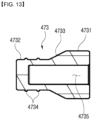
- the plug member 473 is provided with a shock absorbing portion 4731 positioned in the bore, a fastening portion 4732 inserted into the mounting hole 115, and a connecting portion 4733 that connects the shock absorbing portion 4731 and the fastening portion 4732.
- the connecting portion 4733 is formed to be inclined to be in close contact with the inclined surface 19 of the outer housing 11. That is, the connecting portion 473 may be formed in a shape of a cone that becomes gradually narrower toward the fastening portion 4732 from an end of the shock absorbing portion 4711, similar to the inclined surface 19.
- the connecting portion 4733 assists the fastening portion 4732 to prevent the plug member 473 from moving backward.
- the plug member 473 may be formed of a material having elasticity and corrosion resistance, such as rubber.
- the plug member 473 may include an annular projection 4734 that protrudes from an outer circumferential surface thereof.
- the annular projection 4734 may be provided in plural and is in close contact with the side surface 116 of the mounting hole 115 like the O-ring described above to perform a function of preventing leak of grease.
- the plug member 473 may include a recessed space 4735 that is recessed in the longitudinal direction at a front end thereof facing the inner shaft 13.
- the present invention relates to a driveshaft that is used in a drive system of a vehicle, so it has an industrial applicability.
Landscapes
- Engineering & Computer Science (AREA)
- Mechanical Engineering (AREA)
- General Engineering & Computer Science (AREA)
- Ocean & Marine Engineering (AREA)
- Shafts, Cranks, Connecting Bars, And Related Bearings (AREA)
- Vibration Dampers (AREA)
- Motor Power Transmission Devices (AREA)
Description
- The present invention relates to a plunging assembly of a driveshaft used in a drive system of a vehicle and a drive shaft comprising the same.
- A drive shaft used in a drive line of a vehicle includes an intermediate shaft and constant velocity joints installed on both sides thereof.
- Such a drive shaft includes a drive shaft in which an intermediate shaft is configured as a plunging assembly capable of plunging.
- A plunging assembly is generally implemented in the form of a plunging shaft using a ball spline structure. Such a plunging assembly includes a tubular outer housing, an inner shaft and a plunging unit. The plunging unit is interposed between the outer housing and the inner shaft to enable a plunging operation. Ball grooves that are mated to each other are respectively provided in the outer housing and the inner shaft, and the plunging unit includes balls disposed in these ball grooves and a ball cage receiving the balls.
- It is necessary to limit the behavior of the plunging unit and the behavior of the inner shaft in a plunging assembly having such a plunging unit, and for example,
US Patent No. 6,585,602 discloses such a plunging assembly. The plunging assembly of the conventional driveshaft has a plurality of stop rings to limit the behavior of the plunging unit and the inner shaft, and in particular has a structure in which stop rings are provided at both ends of the inner shaft. In this case, there is a problem in that the structure is complicated and machining is difficult because grooves for seating of the stop ring at both ends of the inner shaft must be formed. - In particular, grooves that are formed to mount a stop ring on the inner side of the inner shaft cause a problem that the inner shaft can be broken even at a small torsional torque.
-
- 1. US patent No.
US6,585,602 (date of registration: 2003.07.01 - 2.
JP patent No. 3464460 (date of registration: 2003.08.22 - 3.
JP patent No. 2863114 (date of registration: 1998.12.11 -
KR 10-2017-0142735 A FR 2 838 093 A1 KR 10-1419986 B1 JP 2011-73543 A - The problem to be solved by the present invention is to provide a plunging assembly capable of implementing a stop function of an inner shaft without decreasing a strength of an inner shaft.
- A plunging assembly of a driveshaft according to an embodiment of the present invention includes: an outer housing having a bore having a plurality of outer ball grooves extending in a longitudinal direction; an inner shaft being disposed to be able to undergo relative movement in the longitudinal direction in the bore of the outer housing and having a plurality of inner ball grooves that are paired respectively with the outer ball grooves to form a plurality of ball tracks; a plunging unit connecting the outer housing and the inner shaft to allow a plunging motion and a rotational power transmission between the outer housing and the inner shaft; and a stopper that is provided in the bore of the outer housing to limit relative movement of the inner housing and the inner shaft in a direction in which the inner shaft is inserted into the bore. The outer housing has a mounting hole communicating with the bore, and the stopper is a plug member that is inserted into the mounting hole in a state that a frontal end portion thereof is exposed to the bore.
- According to the invention, the outer housing has an inclined surface connecting the bore and the mounting hole. The plug member includes: a shock absorbing portion located in the bore; a fastening portion inserted into the mounting hole; and a connecting portion connecting the shock absorbing portion and the fixing portion. An outer peripheral surface of the connecting portion is formed to be inclined so as to be in close contact with the inclined surface.
- The outer housing may have a through hole communicating with the bore and the mounting hole is formed by further processing the through hole, and the fastening portion may be fitted in contact with a side surface forming the mounting hole.
- The fastening portion may be assembled to a space formed by a mounting surface in a press-fitting manner.
- The fastening portion may include an annular projection protruding from an outer peripheral surface, and the annular projection may be in close contact with the mounting surface.
- The annular projection may be provided in plural.
- The plug member may be provided with a recessed space recessed in a longitudinal direction from an end facing the inner shaft.
- According to the present invention, by forming a mounting hole connected to a bore of an outer housing and implementing a stop function of an inner shaft via a plug member inserted therein, a stop function of the inner shaft is realized without damaging the strength of the inner shaft.
- In addition, according to the present invention, by forming a slanted surface connecting a bore of the outer housing and the mounting hole and forming a connecting portion that is inclined so as to be in close contact with the inclined surface, it is possible to effectively prevent the plug member from being moved by being pushed by the inner shaft.
-
-
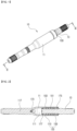
FIG. 1 is a perspective view of a plunging assembly of a driveshaft according to an embodiment not being part of the present invention. -
FIG. 2 is a cross-sectional view taken along a line II-II ofFIG. 1 . -
FIG. 3 is a drawing for explaining a moving-out operation of an outer housing and an inner shaft in a plunging assembly according to an embodiment not being part of the present invention. -
FIG. 4 is a drawing for explaining a moving-in operation of an outer housing and an inner shaft in a plunging assembly according to an embodiment not being part of the present invention. -
FIG. 5 is a view for explaining a process of installing a plug member in an outer housing of a plunging assembly according to an embodiment not being part of the present invention. -
FIG. 6 is a drawing showing a plug member of a plunging assembly according to an embodiment not being part of the present invention. -
FIG. 7 is a cross-sectional view taken along a line VII-VII ofFIG. 6 . -
FIG. 8 is a view showing a plug member according to another embodiment not being part of the present invention. -
FIG. 9 is a cross-sectional view taken along a line IX-IX ofFIG. 8 . -
FIG. 10 is a drawing showing a plug member according to another embodiment not being part of the present invention. -
FIG. 11 is a drawing showing a plunging assembly according to an embodiment of the present invention. -
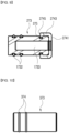
FIG. 12 is a drawing showing a plug member of the plunging assembly ofFIG. 11 . -
FIG. 13 is a cross-sectional view taken along a ling III-III ofFIG. 12 . - Hereinafter, exemplary embodiments will be described in detail with reference to the accompanying drawings.
- Referring to
FIG. 1 and FIG. 2 , aplunging assembly 10 includes anouter housing 11, aninner shaft 13 and aplunging unit 15. Theouter housing 11 may have a tube shape having a through hole along a longitudinal direction thereof, and theinner shaft 13 may be partially inserted into theouter housing 11. Theplunging unit 15 is interposed between theouter housing 11 and theinner shaft 13 so that a plunging operation can occur. Constant velocity joints for transmitting torque may be coupled to both ends exposed to both sides in the state that theouter housing 11 and theinner shaft 13 are assembled to one another. For example, the constant velocity joint may be a Rzeppa joint capable of transmitting rotational power and being articulated. Theouter housing 11, theinner shaft 13 and a pair of constant velocity joints coupled to the both sides thereof according to an embodiment not being part of the present invention may comprise a driveshaft used in a drive system of a vehicle. - The
outer housing 11 has abore 111 extending in a longitudinal direction thereof (horizontal direction inFIG. 3 ), and thebore 111 has a plurality ofouter ball grooves 113 extending in the longitudinal direction. Theouter ball groove 113 may be formed by being recessed in a radially outward direction from a surface forming thebore 111 and may have a semi-circular cross-sectional shape. Theouter ball groove 113 may extend in a predetermined length from an end of the open side of theouter housing 11. The plurality of theouter ball grooves 113 may be arranged at equal intervals along a circumferential direction. - The
inner shaft 13 is inserted into thebore 111 of theouter housing 11 to be relatively movable in a longitudinal direction. That is, theouter housing 11 and theinner shaft 13 are arranged so that relative positions in the longitudinal direction with respect to each other are variable. For example, when theinner shaft 13 is connected to an inner joint member of an in-board joint of a driveshaft of a vehicle, the relative position of theouter housing 11 and theinner shaft 13 can be changed while the position in a longitudinal direction of theouter housing 11 in is changed. - The
inner shaft 13 is provided with a plurality ofinner ball grooves 133 which are respectively paired with a plurality ofouter ball grooves 113 of theouter housing 11 to form a plurality of ball tracks 120. Theinner ball groove 133 may be formed by being recessed in a radially inward direction from the surface of theinner shaft 13 and may have a semi-circular cross-sectional shape. Theinner ball groove 133 may be formed at a position corresponding to the position of the outer ball groove 113 so as to form thetubular ball track 120. At this time, theinner ball groove 133 may extend a predetermined length from the tip of theinner shaft 13 inserted into thebore 111 of theouter housing 11. - The plunging
unit 15 connects theouter housing 11 and theinner shaft 13 to allow a plunging motion and a rotational power transmission between theouter housing 11 and theinner shaft 13. That is, due to the plungingunit 15, the relative movement in the longitudinal direction of theouter housing 11 and theinner shaft 13 is possible, and the delivery of the rotational power, i.e., the torque, between theinner shaft 13 and theouter housing 11 is also possible. - The plunging
unit 15 includes a plurality ofballs 151 and aball cage 153 accommodating them. A plurality ofballs 151 may be arranged in a line in eachball track 120, and for example, fourballs 151 may be disposed in eachball track 120, as exemplarily shown inFIG. 2 . The ball spline structure is formed by the combination of the plungingunit 15 and theball track 120. - The
ball cage 153 accommodates theball 151 and is interposed between theinner shaft 13 and theouter housing 11 to be movable in a longitudinal direction. For example, theball cage 153 may include a plurality of ball pockets 154 for receiving a plurality of balls, respectively. As shown inFIG. 2 , a radially outer portion of theball 151 is disposed in theouter ball groove 113 and a radially inner portion of theball 151 is disposed in theinner ball groove 133 in a state that the center portion of theball 151 is located in theball pocket 154. At this time, theball cage 153 may have a shape of a cylindrical sleeve. - For example, when the
inner shaft 13 rotates, the rotational power is transferred from theinner shaft 13 to theouter housing 11 via theballs 151 that are in close contact with the side of the inner ball groove 133 of theinner shaft 13 and the outer ball groove 113 of theouter housing 11. In addition, when there is a relative movement in the longitudinal direction of theouter housing 11 and theinner shaft 13, theball 151 rolls or slides to undergo a change of the relative positions with respect to theouter housing 11 and/or theinner shaft 13. - A movement limiting unit 17 is provided that operates to limit the longitudinal movement of the plunging
unit 15 and the relative movement of theouter housing 11 and theinner shaft 13 in the longitudinal direction. The movement limiting unit 17 may include a first moving-instopper 171, a second moving-instopper 173, a first moving-out stopper 175 and a second moving-out stopper 177. - The first moving-
out stopper 175 limits the relative movement of the plungingunit 15 in the direction in which the plungingunit 15 is discharged out of thebore 111. As shown inFIG. 3 , the first moving-out stopper 175 is a stop ring inserted into a groove formed in an inner circumferential surface of an open side end portion of theouter housing 11 into which theinner shaft 13 is inserted. Theball cage 153 or theball 151 of the plungingunit 15 may be formed to be blocked by thestop ring 175. When theball cage 153 contacts thestop ring 175 when theball cage 153 moves relative to theouter housing 11 in the direction discharged from thebore 111, the relative movement of the plungingunit 15 is prevented. Relative movement of the plungingunit 15 in the direction exiting thebore 111 may be caused by the movement of theouter housing 11 in the left direction inFIG. 2 . - The second moving-
out stopper 177 limits the relative movement of theinner shaft 13 in the direction in which theinner shaft 13 is discharged out of thebore 111. As illustrated inFIG. 3 , the second moving-out stopper 177 may be a stop ring installed in a groove formed at the frontal end portion of theinner shaft 13. Theball cage 153 or theball 151 of the plungingunit 15 may be formed to be blocked by thestop ring 177. When theouter housing 11 and theinner shaft 13 move relative to each other in the direction in which theinner shaft 13 is discharged out of thebore 111, thestop ring 177 is blocked against the plungingunit 15 that is blocked by thestop ring 175, and thereby theinner shaft 13 can no longer move relatively. Relative movement of theinner shaft 13 in the direction exiting from thebore 111 may be caused by the movement of theouter housing 11 in the left direction inFIG. 3 . -
FIG. 3 illustrates the state that theinner shaft 13 is maximally discharged out of theouter housing 11, and in this state theball cage 153 is blocked by the first moving-out stopper 175 and the second moving-out stopper 177 is blocked by theball cage 153. Therefore, an additional moving-out motion is blocked. - The first moving-in
stopper 171 limits the relative movement of the plungingunit 15 in the direction in which the plungingunit 15 is inserted into thebore 111. As shown inFIG. 4 , the first moving-instopper 171 may be a blocking wall which is protruded in a radially inward direction from the inner end of the outer ball groove 113 of theouter housing 11. Theball cage 153 or theball 151 of the plungingunit 15 may be formed to be blocked by the blockingwall 171. When the plungingunit 15 moves relatively in a direction in which it is inserted into thebore 111, the plungingunit 15 is prevented from moving further if the plungingunit 15 contacts the blockingwall 171. The relative movement of the plungingunit 15 in the direction in which it is inserted into thebore 111 can be caused by the movement of theouter housing 11 in the right direction inFIG. 2 . - The second moving-in
stopper 173 limits the relative movement of theinner shaft 13 in the direction in which it is inserted into thebore 111. As illustrated inFIG. 4 , the second moving-instopper 173 may be a plug member installed in theouter housing 11. At this time, theouter housing 11 may include a mountinghole 115 communicating with thebore 111, and theplug member 173 is inserted into the mountinghole 115 in a state in which the front end portion (right end portion inFIG. 2 ) is exposed to thebore 111. Accordingly, if theinner shaft 13 moves relatively in an insertion direction within thebore 111 to contact theplug member 173 as illustrated inFIG. 4 , further movement of theinner shaft 13 is blocked. - The
outer housing 11 may be provided with a throughhole 117 communicating with thebore 111, and the mountinghole 115 may be formed by further processing a side surface of the throughhole 117. For example, as shown in (a) ofFIG. 5 , the mountinghole 115 may be formed by further cutting a region of the side surface of the throughhole 117 of theouter housing 11 where theplug member 173 is inserted. Accordingly, a blockingwall 118 is formed at an end of the mountinghole 115. Then, as shown in (b) ofFIG. 5 , theplug member 173 is inserted into the mountinghole 115, and theinner shaft 13 can be inserted into thebore 111. - At this time, the
plug member 173 may be assembled to the mountinghole 115 in a press-fitting manner so as not to be separated from the mountinghole 115. For example, theplug member 173 may be formed of a shock-resistant metal material such as aluminum. With theplug member 173, theinner shaft 13 can be prevented from directly colliding with the inner surface of theouter housing 11 during moving-in motion. - Referring to
FIG. 6 andFIG. 7 , theplug member 173 may have a substantially cylindrical shape, and an O-ring 1732 may be installed in a groove 1173 that is formed on an outer circumferential surface of theplug member 173. It is preferable that grease is applied for smooth movement of theball 151 of the plungingunit 15, and the O-ring 1732 can prevent the applied grease from leaking to the outside through the throughhole 117 of theouter housing 11. At this time, a plurality of O-rings 1732 may be provided, and for example, as illustrated inFIG. 6 andFIG. 7 , two O-rings 1732 may be provided. By providing a plurality of O-rings 1732, the assembledplug member 173 can maintain a predetermined arrangement state. - Further, as shown in
FIG. 7 , the plug member 73 may be provided with a recessedspace 1733 that is recessed in a longitudinal direction from the front end thereof facing theinner shaft 13. The weight of the plug member 73 may be reduced due to the recessedspace 1733. - Hereinafter, a plug member according to another embodiment not being part of the present invention will be described with reference to
FIG. 8 andFIG. 9 . The same reference numerals are used for the same parts as described above, and the common descriptions will be omitted. - Referring to
FIG. 8 andFIG. 9 , aplug member 273 includes anelastic damper 274 that is fastened to a portion facing an end of theinner shaft 13. Referring toFIG. 9 , theelastic damper 274 includes ashock absorbing portion 2741 that faces an end portion of theinner shaft 13, anextension portion 2743 that extends along the side of theplug member 273 from the outer end of theshock absorbing portion 2741, and afastening protrusion 2745 that extends in a radially inward direction from an end of theextension portion 2743 and is inserted into afastening groove 275 that is formed on the outer circumferential surface of theplug member 273. Theshock absorbing portion 2741 is a portion where the end of theinner shaft 13 collides and functions to absorb shock in the event of the collision with theinner shaft 13. Theelastic damper 274 may be assembled to theplug member 273 in a press-fitting manner. - Hereinafter, a plug member according to another embodiment not being part of the present invention will be described with reference to
FIG. 10 . The same reference numerals are used for the same parts as described above, and the common descriptions are omitted. - As shown in
FIG. 10 , aplug member 373 has anannular projection 374 protruding from an outer circumferential surface thereof. Theannular projection 374 may be provided in plural, and like the O-ring described above, is in close contact with theside surface 116 of the mountinghole 115 to perform a function of preventing leak of grease. - Hereinafter, a plunging assembly according to an embodiment of the present invention will be described with reference to
FIG. 11 to FIG. 13 . - Referring to
FIG. 11 , theouter housing 11 includes aninclined surface 19 connecting thebore 111 and the mountinghole 15, and aplug member 473 is configured to be supported on theinclined surface 19 so as to be more effectively prevented from moving backward by the collision with theinner shaft 13. At this time, the diameter of the mountinghole 115 is formed to be smaller than the diameter of thebore 111, and theinclined surface 19 may have a cone shape that becomes gradually narrower toward an entrance of the mountinghole 15 from an end of thebore 111. - As shown in
FIG. 11 and FIG. 12 , theplug member 473 is provided with ashock absorbing portion 4731 positioned in the bore, afastening portion 4732 inserted into the mountinghole 115, and a connectingportion 4733 that connects theshock absorbing portion 4731 and thefastening portion 4732. At this time, as shown inFIG. 11 , the connectingportion 4733 is formed to be inclined to be in close contact with theinclined surface 19 of theouter housing 11. That is, the connectingportion 473 may be formed in a shape of a cone that becomes gradually narrower toward thefastening portion 4732 from an end of the shock absorbing portion 4711, similar to theinclined surface 19. By this structure, the connectingportion 4733 assists thefastening portion 4732 to prevent theplug member 473 from moving backward. Theplug member 473 may be formed of a material having elasticity and corrosion resistance, such as rubber. - Meanwhile, as illustrated in
FIG. 12 andFIG. 13 , theplug member 473 may include anannular projection 4734 that protrudes from an outer circumferential surface thereof. Theannular projection 4734 may be provided in plural and is in close contact with theside surface 116 of the mountinghole 115 like the O-ring described above to perform a function of preventing leak of grease. - Also, as shown in
FIG. 13 , theplug member 473 may include a recessedspace 4735 that is recessed in the longitudinal direction at a front end thereof facing theinner shaft 13. - While this invention has been described in connection with what is presently considered to be practical exemplary embodiments, it is to be understood that the invention is not limited to the disclosed embodiment, but, on the contrary, is intended to cover various modifications and equivalent arrangements included within the scope of the appended claims.
- The present invention relates to a driveshaft that is used in a drive system of a vehicle, so it has an industrial applicability.
Claims (6)
- A plunging assembly of a driveshaft comprising:an outer housing (11) having a bore (111) having a plurality of outer ball grooves (113) extending in a longitudinal direction;an inner shaft (13) being disposed to be able to undergo relative movement in the longitudinal direction in the bore (111) of the outer housing (11) and having a plurality of inner ball grooves (133) that are paired respectively with the outer ball grooves (113) to form a plurality of ball tracks (120);a plunging unit (15) connecting the outer housing (11) and the inner shaft (13) to allow a plunging motion and a rotational power transmission between the outer housing (11) and the inner shaft (13); anda stopper (473) that is provided in the bore (111) of the outer housing (11) to limit relative movement of the inner housing (11) and the inner shaft (13) in a direction in which the inner shaft (13) is inserted into the bore (111),characterized in that the outer housing (11) has a mounting hole (115) communicating with the bore (111),wherein the stopper (473) is a plug member that is inserted into the mounting hole (115) in a state that a frontal end portion thereof is exposed to the bore (111),wherein the outer housing (11) has an inclined surface (19) connecting the bore (111) and the mounting hole (115),wherein the plug member (473) comprises:a shock absorbing portion (4731) located in the bore (111),a fastening portion (4732) inserted into the mounting hole (115), anda connecting portion (4733) connecting the shock absorbing portion (4731) and the fixing portion (4732), andwherein an outer peripheral surface of the connecting portion (4733) is formed to be inclined so as to be in close contact with the inclined surface (19).
- The plunging assembly of a driveshaft of claim 1, wherein the outer housing (11) has a through hole (117) communicating with the bore (111) and the mounting hole (115) is formed by further processing the through hole (117), and wherein the fastening portion (4732) is fitted in contact with a side surface (116) forming the mounting hole (115).
- The plunging assembly of a driveshaft of claim 2, wherein the fastening portion (4732) is assembled to a space formed by a mounting surface (116) in a press-fitting manner.
- The plunging assembly of a driveshaft of claim 2, wherein the fastening portion (4732) comprises an annular projection (4734) protruding from an outer peripheral surface, and wherein the annular projection (4734) is in close contact with the mounting surface (116).
- The plunging assembly of a driveshaft of claim 4, wherein the annular projection (4734) is provided in plural.
- The plunging assembly of a driveshaft of claim 1, wherein the plug member (473) is provided with a recessed space (4735) recessed in a longitudinal direction from an end facing the inner shaft (13).
Applications Claiming Priority (2)
| Application Number | Priority Date | Filing Date | Title |
|---|---|---|---|
| KR1020180007503A KR102067649B1 (en) | 2018-01-22 | 2018-01-22 | Plunging assembly for driveshaft |
| PCT/KR2019/000515 WO2019143079A1 (en) | 2018-01-22 | 2019-01-14 | Plunging assembly of drive shaft |
Publications (3)
| Publication Number | Publication Date |
|---|---|
| EP3730810A1 EP3730810A1 (en) | 2020-10-28 |
| EP3730810A4 EP3730810A4 (en) | 2021-09-29 |
| EP3730810B1 true EP3730810B1 (en) | 2023-11-22 |
Family
ID=67301084
Family Applications (1)
| Application Number | Title | Priority Date | Filing Date |
|---|---|---|---|
| EP19741163.0A Active EP3730810B1 (en) | 2018-01-22 | 2019-01-14 | Plunging assembly of drive shaft |
Country Status (7)
| Country | Link |
|---|---|
| US (1) | US11767877B2 (en) |
| EP (1) | EP3730810B1 (en) |
| JP (1) | JP6993517B2 (en) |
| KR (1) | KR102067649B1 (en) |
| CN (1) | CN111630289B (en) |
| PL (1) | PL3730810T3 (en) |
| WO (1) | WO2019143079A1 (en) |
Families Citing this family (5)
| Publication number | Priority date | Publication date | Assignee | Title |
|---|---|---|---|---|
| GB2538511B (en) * | 2015-05-18 | 2020-12-16 | Lentus Composites Ltd | Shaft arrangement |
| JP6181219B1 (en) * | 2016-02-16 | 2017-08-16 | Ntn株式会社 | Method for forging outer joint member of constant velocity universal joint |
| KR20210118546A (en) * | 2020-03-23 | 2021-10-01 | 서한산업(주) | A drive shaft including magnectic layer |
| KR20220126162A (en) | 2021-03-08 | 2022-09-15 | 씨제이제일제당 (주) | Method for Preparing Frozen Pizza Dough |
| CN117145882B (en) * | 2023-10-27 | 2024-02-02 | 万向钱潮股份公司 | Zxfoom spline shaft spline shaft Assembly vehicle and method for manufacturing the same |
Family Cites Families (16)
| Publication number | Priority date | Publication date | Assignee | Title |
|---|---|---|---|---|
| DE4419373C2 (en) | 1994-06-03 | 1998-01-29 | Loehr & Bromkamp Gmbh | PTO shaft with sliding part |
| JP3353030B2 (en) * | 1997-11-18 | 2002-12-03 | 松井ワルターシャイド株式会社 | Drive shaft |
| DE10008556A1 (en) * | 2000-02-24 | 2001-09-06 | Gkn Loebro Gmbh | Plunging assembly for drive shaft used in drive line of motor vehicle, has outer and inner running grooves formed on inner and outer sections and having different effective lengths |
| US6348002B1 (en) * | 2000-02-24 | 2002-02-19 | Spicer Driveshaft, Inc. | Slip yoke sealing and positioning plug |
| JP3464460B2 (en) | 2000-02-24 | 2003-11-10 | ジー・ケー・エヌ・レブロ・ゲゼルシャフト・ミット・ベシュレンクテル・ハフツング | Drive shaft |
| DE10132658C1 (en) * | 2001-07-05 | 2003-04-24 | Gkn Loebro Gmbh | Longitudinal displacement unit |
| FR2838093B1 (en) * | 2002-04-03 | 2004-09-24 | Delphi Tech Inc | INTERMEDIATE SHAFT FORK |
| DE102008031396A1 (en) * | 2007-07-26 | 2009-02-26 | Bf New Technologies Gmbh | Rolling unit and PTO shaft hereby |
| KR101007422B1 (en) | 2008-12-31 | 2011-01-12 | 김정섭 | Steering shaft with shock absorber |
| JP5347881B2 (en) * | 2009-09-30 | 2013-11-20 | 日本精工株式会社 | Telescopic shaft for vehicle steering |
| KR101419986B1 (en) * | 2011-11-03 | 2014-07-16 | 주식회사 만도 | Intermediate Shaft of Steering Apparatus for Vehicle |
| JP2016020146A (en) | 2014-07-14 | 2016-02-04 | 日本精工株式会社 | Rack and pinion type steering gear unit |
| JP6436486B2 (en) * | 2014-12-25 | 2018-12-12 | 株式会社ジェイテクト | Telescopic shaft and steering device |
| KR101637850B1 (en) | 2015-09-08 | 2016-07-07 | 현대자동차주식회사 | Propeller shaft with locking device |
| JP2017109529A (en) | 2015-12-14 | 2017-06-22 | 株式会社シマノ | Crank assembly for bicycle |
| KR101872493B1 (en) * | 2016-06-20 | 2018-06-28 | 이래에이엠에스 주식회사 | Plunging assembly for driveshaft and driveshaft including same |
-
2018
- 2018-01-22 KR KR1020180007503A patent/KR102067649B1/en active Active
-
2019
- 2019-01-14 JP JP2020540544A patent/JP6993517B2/en active Active
- 2019-01-14 EP EP19741163.0A patent/EP3730810B1/en active Active
- 2019-01-14 WO PCT/KR2019/000515 patent/WO2019143079A1/en not_active Ceased
- 2019-01-14 US US16/963,590 patent/US11767877B2/en active Active
- 2019-01-14 CN CN201980009701.2A patent/CN111630289B/en active Active
- 2019-01-14 PL PL19741163.0T patent/PL3730810T3/en unknown
Also Published As
| Publication number | Publication date |
|---|---|
| WO2019143079A1 (en) | 2019-07-25 |
| US20210062860A1 (en) | 2021-03-04 |
| US11767877B2 (en) | 2023-09-26 |
| EP3730810A4 (en) | 2021-09-29 |
| JP6993517B2 (en) | 2022-01-13 |
| EP3730810A1 (en) | 2020-10-28 |
| JP2021512257A (en) | 2021-05-13 |
| CN111630289A (en) | 2020-09-04 |
| KR20190089275A (en) | 2019-07-31 |
| KR102067649B1 (en) | 2020-01-17 |
| PL3730810T3 (en) | 2024-05-06 |
| CN111630289B (en) | 2022-07-08 |
Similar Documents
| Publication | Publication Date | Title |
|---|---|---|
| EP3730810B1 (en) | Plunging assembly of drive shaft | |
| US6585602B2 (en) | Plunging assembly for a driveshaft | |
| US6299544B1 (en) | Double offset joint with centering means for cage | |
| KR101872493B1 (en) | Plunging assembly for driveshaft and driveshaft including same | |
| KR102131625B1 (en) | Plunging assembly for driveshaft | |
| EP2896846B1 (en) | Shaft-to-universal joint coupling structure | |
| KR102179859B1 (en) | Plunging assembly for driveshaft and driveshaft including same | |
| EP3450783B1 (en) | Constant velocity universal joint | |
| US9115764B2 (en) | Double-roller-type tripod constant-velocity joint | |
| CN107709810A (en) | Fixed Constant Velocity Universal Coupling | |
| CN108006092B (en) | Constant velocity joint | |
| JP4554181B2 (en) | Fixed type constant velocity universal joint | |
| KR20180009517A (en) | Plunging assembly for driveshaft and driveshaft including same | |
| CN109139724B (en) | Ball cage for VL and CG gimbals | |
| JP2007040425A (en) | Constant velocity universal joint | |
| JP5163930B2 (en) | Ball type constant velocity joint | |
| KR102491273B1 (en) | Constant velocity joint having grease retainer | |
| JP4230274B2 (en) | Constant velocity fixed ball joint | |
| JP2021156300A (en) | Shaft connecting structure of constant velocity universal joint | |
| KR20230009557A (en) | Drive shaft for vehicle | |
| WO2017082068A1 (en) | Sliding constant-velocity universal joint | |
| JP2007239878A (en) | Drive shaft boot | |
| JP4242409B2 (en) | Fixed type constant velocity universal joint | |
| JP2004183902A (en) | Fixed type constant velocity universal joint | |
| WO2022185425A1 (en) | Constant velocity joint |
Legal Events
| Date | Code | Title | Description |
|---|---|---|---|
| STAA | Information on the status of an ep patent application or granted ep patent |
Free format text: STATUS: THE INTERNATIONAL PUBLICATION HAS BEEN MADE |
|
| PUAI | Public reference made under article 153(3) epc to a published international application that has entered the european phase |
Free format text: ORIGINAL CODE: 0009012 |
|
| STAA | Information on the status of an ep patent application or granted ep patent |
Free format text: STATUS: REQUEST FOR EXAMINATION WAS MADE |
|
| 17P | Request for examination filed |
Effective date: 20200722 |
|
| AK | Designated contracting states |
Kind code of ref document: A1 Designated state(s): AL AT BE BG CH CY CZ DE DK EE ES FI FR GB GR HR HU IE IS IT LI LT LU LV MC MK MT NL NO PL PT RO RS SE SI SK SM TR |
|
| AX | Request for extension of the european patent |
Extension state: BA ME |
|
| DAV | Request for validation of the european patent (deleted) | ||
| DAX | Request for extension of the european patent (deleted) | ||
| A4 | Supplementary search report drawn up and despatched |
Effective date: 20210827 |
|
| RIC1 | Information provided on ipc code assigned before grant |
Ipc: B60B 35/12 20060101ALI20210823BHEP Ipc: F16C 3/035 20060101ALI20210823BHEP Ipc: F16D 3/223 20110101AFI20210823BHEP |
|
| GRAP | Despatch of communication of intention to grant a patent |
Free format text: ORIGINAL CODE: EPIDOSNIGR1 |
|
| STAA | Information on the status of an ep patent application or granted ep patent |
Free format text: STATUS: GRANT OF PATENT IS INTENDED |
|
| INTG | Intention to grant announced |
Effective date: 20230609 |
|
| GRAS | Grant fee paid |
Free format text: ORIGINAL CODE: EPIDOSNIGR3 |
|
| GRAA | (expected) grant |
Free format text: ORIGINAL CODE: 0009210 |
|
| STAA | Information on the status of an ep patent application or granted ep patent |
Free format text: STATUS: THE PATENT HAS BEEN GRANTED |
|
| AK | Designated contracting states |
Kind code of ref document: B1 Designated state(s): AL AT BE BG CH CY CZ DE DK EE ES FI FR GB GR HR HU IE IS IT LI LT LU LV MC MK MT NL NO PL PT RO RS SE SI SK SM TR |
|
| REG | Reference to a national code |
Ref country code: GB Ref legal event code: FG4D |
|
| REG | Reference to a national code |
Ref country code: CH Ref legal event code: EP Ref country code: DE Ref legal event code: R096 Ref document number: 602019041895 Country of ref document: DE |
|
| REG | Reference to a national code |
Ref country code: IE Ref legal event code: FG4D |
|
| REG | Reference to a national code |
Ref country code: SE Ref legal event code: TRGR |
|
| REG | Reference to a national code |
Ref country code: LT Ref legal event code: MG9D |
|
| REG | Reference to a national code |
Ref country code: NL Ref legal event code: MP Effective date: 20231122 |
|
| PG25 | Lapsed in a contracting state [announced via postgrant information from national office to epo] |
Ref country code: GR Free format text: LAPSE BECAUSE OF FAILURE TO SUBMIT A TRANSLATION OF THE DESCRIPTION OR TO PAY THE FEE WITHIN THE PRESCRIBED TIME-LIMIT Effective date: 20240223 |
|
| PG25 | Lapsed in a contracting state [announced via postgrant information from national office to epo] |
Ref country code: IS Free format text: LAPSE BECAUSE OF FAILURE TO SUBMIT A TRANSLATION OF THE DESCRIPTION OR TO PAY THE FEE WITHIN THE PRESCRIBED TIME-LIMIT Effective date: 20240322 |
|
| PG25 | Lapsed in a contracting state [announced via postgrant information from national office to epo] |
Ref country code: LT Free format text: LAPSE BECAUSE OF FAILURE TO SUBMIT A TRANSLATION OF THE DESCRIPTION OR TO PAY THE FEE WITHIN THE PRESCRIBED TIME-LIMIT Effective date: 20231122 |
|
| REG | Reference to a national code |
Ref country code: AT Ref legal event code: MK05 Ref document number: 1634105 Country of ref document: AT Kind code of ref document: T Effective date: 20231122 |
|
| PG25 | Lapsed in a contracting state [announced via postgrant information from national office to epo] |
Ref country code: NL Free format text: LAPSE BECAUSE OF FAILURE TO SUBMIT A TRANSLATION OF THE DESCRIPTION OR TO PAY THE FEE WITHIN THE PRESCRIBED TIME-LIMIT Effective date: 20231122 |
|
| PG25 | Lapsed in a contracting state [announced via postgrant information from national office to epo] |
Ref country code: AT Free format text: LAPSE BECAUSE OF FAILURE TO SUBMIT A TRANSLATION OF THE DESCRIPTION OR TO PAY THE FEE WITHIN THE PRESCRIBED TIME-LIMIT Effective date: 20231122 |
|
| PG25 | Lapsed in a contracting state [announced via postgrant information from national office to epo] |
Ref country code: ES Free format text: LAPSE BECAUSE OF FAILURE TO SUBMIT A TRANSLATION OF THE DESCRIPTION OR TO PAY THE FEE WITHIN THE PRESCRIBED TIME-LIMIT Effective date: 20231122 |
|
| PG25 | Lapsed in a contracting state [announced via postgrant information from national office to epo] |
Ref country code: NL Free format text: LAPSE BECAUSE OF FAILURE TO SUBMIT A TRANSLATION OF THE DESCRIPTION OR TO PAY THE FEE WITHIN THE PRESCRIBED TIME-LIMIT Effective date: 20231122 Ref country code: LT Free format text: LAPSE BECAUSE OF FAILURE TO SUBMIT A TRANSLATION OF THE DESCRIPTION OR TO PAY THE FEE WITHIN THE PRESCRIBED TIME-LIMIT Effective date: 20231122 Ref country code: IS Free format text: LAPSE BECAUSE OF FAILURE TO SUBMIT A TRANSLATION OF THE DESCRIPTION OR TO PAY THE FEE WITHIN THE PRESCRIBED TIME-LIMIT Effective date: 20240322 Ref country code: GR Free format text: LAPSE BECAUSE OF FAILURE TO SUBMIT A TRANSLATION OF THE DESCRIPTION OR TO PAY THE FEE WITHIN THE PRESCRIBED TIME-LIMIT Effective date: 20240223 Ref country code: ES Free format text: LAPSE BECAUSE OF FAILURE TO SUBMIT A TRANSLATION OF THE DESCRIPTION OR TO PAY THE FEE WITHIN THE PRESCRIBED TIME-LIMIT Effective date: 20231122 Ref country code: BG Free format text: LAPSE BECAUSE OF FAILURE TO SUBMIT A TRANSLATION OF THE DESCRIPTION OR TO PAY THE FEE WITHIN THE PRESCRIBED TIME-LIMIT Effective date: 20240222 Ref country code: AT Free format text: LAPSE BECAUSE OF FAILURE TO SUBMIT A TRANSLATION OF THE DESCRIPTION OR TO PAY THE FEE WITHIN THE PRESCRIBED TIME-LIMIT Effective date: 20231122 Ref country code: PT Free format text: LAPSE BECAUSE OF FAILURE TO SUBMIT A TRANSLATION OF THE DESCRIPTION OR TO PAY THE FEE WITHIN THE PRESCRIBED TIME-LIMIT Effective date: 20240322 |
|
| PG25 | Lapsed in a contracting state [announced via postgrant information from national office to epo] |
Ref country code: RS Free format text: LAPSE BECAUSE OF FAILURE TO SUBMIT A TRANSLATION OF THE DESCRIPTION OR TO PAY THE FEE WITHIN THE PRESCRIBED TIME-LIMIT Effective date: 20231122 Ref country code: NO Free format text: LAPSE BECAUSE OF FAILURE TO SUBMIT A TRANSLATION OF THE DESCRIPTION OR TO PAY THE FEE WITHIN THE PRESCRIBED TIME-LIMIT Effective date: 20240222 Ref country code: LV Free format text: LAPSE BECAUSE OF FAILURE TO SUBMIT A TRANSLATION OF THE DESCRIPTION OR TO PAY THE FEE WITHIN THE PRESCRIBED TIME-LIMIT Effective date: 20231122 Ref country code: HR Free format text: LAPSE BECAUSE OF FAILURE TO SUBMIT A TRANSLATION OF THE DESCRIPTION OR TO PAY THE FEE WITHIN THE PRESCRIBED TIME-LIMIT Effective date: 20231122 |
|
| PG25 | Lapsed in a contracting state [announced via postgrant information from national office to epo] |
Ref country code: DK Free format text: LAPSE BECAUSE OF FAILURE TO SUBMIT A TRANSLATION OF THE DESCRIPTION OR TO PAY THE FEE WITHIN THE PRESCRIBED TIME-LIMIT Effective date: 20231122 |
|
| PG25 | Lapsed in a contracting state [announced via postgrant information from national office to epo] |
Ref country code: CZ Free format text: LAPSE BECAUSE OF FAILURE TO SUBMIT A TRANSLATION OF THE DESCRIPTION OR TO PAY THE FEE WITHIN THE PRESCRIBED TIME-LIMIT Effective date: 20231122 |
|
| PG25 | Lapsed in a contracting state [announced via postgrant information from national office to epo] |
Ref country code: SK Free format text: LAPSE BECAUSE OF FAILURE TO SUBMIT A TRANSLATION OF THE DESCRIPTION OR TO PAY THE FEE WITHIN THE PRESCRIBED TIME-LIMIT Effective date: 20231122 |
|
| PG25 | Lapsed in a contracting state [announced via postgrant information from national office to epo] |
Ref country code: SM Free format text: LAPSE BECAUSE OF FAILURE TO SUBMIT A TRANSLATION OF THE DESCRIPTION OR TO PAY THE FEE WITHIN THE PRESCRIBED TIME-LIMIT Effective date: 20231122 Ref country code: SK Free format text: LAPSE BECAUSE OF FAILURE TO SUBMIT A TRANSLATION OF THE DESCRIPTION OR TO PAY THE FEE WITHIN THE PRESCRIBED TIME-LIMIT Effective date: 20231122 Ref country code: RO Free format text: LAPSE BECAUSE OF FAILURE TO SUBMIT A TRANSLATION OF THE DESCRIPTION OR TO PAY THE FEE WITHIN THE PRESCRIBED TIME-LIMIT Effective date: 20231122 Ref country code: EE Free format text: LAPSE BECAUSE OF FAILURE TO SUBMIT A TRANSLATION OF THE DESCRIPTION OR TO PAY THE FEE WITHIN THE PRESCRIBED TIME-LIMIT Effective date: 20231122 Ref country code: DK Free format text: LAPSE BECAUSE OF FAILURE TO SUBMIT A TRANSLATION OF THE DESCRIPTION OR TO PAY THE FEE WITHIN THE PRESCRIBED TIME-LIMIT Effective date: 20231122 Ref country code: CZ Free format text: LAPSE BECAUSE OF FAILURE TO SUBMIT A TRANSLATION OF THE DESCRIPTION OR TO PAY THE FEE WITHIN THE PRESCRIBED TIME-LIMIT Effective date: 20231122 |
|
| REG | Reference to a national code |
Ref country code: DE Ref legal event code: R097 Ref document number: 602019041895 Country of ref document: DE |
|
| PG25 | Lapsed in a contracting state [announced via postgrant information from national office to epo] |
Ref country code: MC Free format text: LAPSE BECAUSE OF FAILURE TO SUBMIT A TRANSLATION OF THE DESCRIPTION OR TO PAY THE FEE WITHIN THE PRESCRIBED TIME-LIMIT Effective date: 20231122 |
|
| PG25 | Lapsed in a contracting state [announced via postgrant information from national office to epo] |
Ref country code: MC Free format text: LAPSE BECAUSE OF FAILURE TO SUBMIT A TRANSLATION OF THE DESCRIPTION OR TO PAY THE FEE WITHIN THE PRESCRIBED TIME-LIMIT Effective date: 20231122 |
|
| REG | Reference to a national code |
Ref country code: CH Ref legal event code: PL |
|
| PG25 | Lapsed in a contracting state [announced via postgrant information from national office to epo] |
Ref country code: LU Free format text: LAPSE BECAUSE OF NON-PAYMENT OF DUE FEES Effective date: 20240114 |
|
| PLBE | No opposition filed within time limit |
Free format text: ORIGINAL CODE: 0009261 |
|
| STAA | Information on the status of an ep patent application or granted ep patent |
Free format text: STATUS: NO OPPOSITION FILED WITHIN TIME LIMIT |
|
| PG25 | Lapsed in a contracting state [announced via postgrant information from national office to epo] |
Ref country code: LU Free format text: LAPSE BECAUSE OF NON-PAYMENT OF DUE FEES Effective date: 20240114 |
|
| PG25 | Lapsed in a contracting state [announced via postgrant information from national office to epo] |
Ref country code: BE Free format text: LAPSE BECAUSE OF NON-PAYMENT OF DUE FEES Effective date: 20240131 |
|
| PG25 | Lapsed in a contracting state [announced via postgrant information from national office to epo] |
Ref country code: CH Free format text: LAPSE BECAUSE OF NON-PAYMENT OF DUE FEES Effective date: 20240131 |
|
| PG25 | Lapsed in a contracting state [announced via postgrant information from national office to epo] |
Ref country code: SI Free format text: LAPSE BECAUSE OF FAILURE TO SUBMIT A TRANSLATION OF THE DESCRIPTION OR TO PAY THE FEE WITHIN THE PRESCRIBED TIME-LIMIT Effective date: 20231122 |
|
| 26N | No opposition filed |
Effective date: 20240823 |
|
| PG25 | Lapsed in a contracting state [announced via postgrant information from national office to epo] |
Ref country code: SI Free format text: LAPSE BECAUSE OF FAILURE TO SUBMIT A TRANSLATION OF THE DESCRIPTION OR TO PAY THE FEE WITHIN THE PRESCRIBED TIME-LIMIT Effective date: 20231122 Ref country code: CH Free format text: LAPSE BECAUSE OF NON-PAYMENT OF DUE FEES Effective date: 20240131 Ref country code: BE Free format text: LAPSE BECAUSE OF NON-PAYMENT OF DUE FEES Effective date: 20240131 |
|
| REG | Reference to a national code |
Ref country code: BE Ref legal event code: MM Effective date: 20240131 |
|
| PGFP | Annual fee paid to national office [announced via postgrant information from national office to epo] |
Ref country code: PL Payment date: 20241216 Year of fee payment: 7 |
|
| PGFP | Annual fee paid to national office [announced via postgrant information from national office to epo] |
Ref country code: GB Payment date: 20241205 Year of fee payment: 7 |
|
| PG25 | Lapsed in a contracting state [announced via postgrant information from national office to epo] |
Ref country code: IE Free format text: LAPSE BECAUSE OF NON-PAYMENT OF DUE FEES Effective date: 20240114 |
|
| PGFP | Annual fee paid to national office [announced via postgrant information from national office to epo] |
Ref country code: SE Payment date: 20241212 Year of fee payment: 7 |
|
| PG25 | Lapsed in a contracting state [announced via postgrant information from national office to epo] |
Ref country code: IE Free format text: LAPSE BECAUSE OF NON-PAYMENT OF DUE FEES Effective date: 20240114 |
|
| PGFP | Annual fee paid to national office [announced via postgrant information from national office to epo] |
Ref country code: IT Payment date: 20241210 Year of fee payment: 7 |
|
| PG25 | Lapsed in a contracting state [announced via postgrant information from national office to epo] |
Ref country code: CY Free format text: LAPSE BECAUSE OF FAILURE TO SUBMIT A TRANSLATION OF THE DESCRIPTION OR TO PAY THE FEE WITHIN THE PRESCRIBED TIME-LIMIT; INVALID AB INITIO Effective date: 20190114 |
|
| REG | Reference to a national code |
Ref country code: DE Ref legal event code: R081 Ref document number: 602019041895 Country of ref document: DE Owner name: HANSAE MOBILITY CO., LTD., DAEGU, KR Free format text: FORMER OWNER: ERAE AMS CO., LTD., DAEGU, KR |
|
| PG25 | Lapsed in a contracting state [announced via postgrant information from national office to epo] |
Ref country code: HU Free format text: LAPSE BECAUSE OF FAILURE TO SUBMIT A TRANSLATION OF THE DESCRIPTION OR TO PAY THE FEE WITHIN THE PRESCRIBED TIME-LIMIT; INVALID AB INITIO Effective date: 20190114 |
|
| PG25 | Lapsed in a contracting state [announced via postgrant information from national office to epo] |
Ref country code: FI Free format text: LAPSE BECAUSE OF FAILURE TO SUBMIT A TRANSLATION OF THE DESCRIPTION OR TO PAY THE FEE WITHIN THE PRESCRIBED TIME-LIMIT Effective date: 20231122 |
|
| PG25 | Lapsed in a contracting state [announced via postgrant information from national office to epo] |
Ref country code: TR Free format text: LAPSE BECAUSE OF FAILURE TO SUBMIT A TRANSLATION OF THE DESCRIPTION OR TO PAY THE FEE WITHIN THE PRESCRIBED TIME-LIMIT Effective date: 20231122 |
|
| PGFP | Annual fee paid to national office [announced via postgrant information from national office to epo] |
Ref country code: FR Payment date: 20251208 Year of fee payment: 8 |
|
| PGFP | Annual fee paid to national office [announced via postgrant information from national office to epo] |
Ref country code: DE Payment date: 20251203 Year of fee payment: 8 |