EP3730804A1 - Fluid pressure control device - Google Patents
Fluid pressure control device Download PDFInfo
- Publication number
- EP3730804A1 EP3730804A1 EP19878985.1A EP19878985A EP3730804A1 EP 3730804 A1 EP3730804 A1 EP 3730804A1 EP 19878985 A EP19878985 A EP 19878985A EP 3730804 A1 EP3730804 A1 EP 3730804A1
- Authority
- EP
- European Patent Office
- Prior art keywords
- passage
- pump
- spool
- valve
- switching
- Prior art date
- Legal status (The legal status is an assumption and is not a legal conclusion. Google has not performed a legal analysis and makes no representation as to the accuracy of the status listed.)
- Pending
Links
Images




Classifications
-
- F—MECHANICAL ENGINEERING; LIGHTING; HEATING; WEAPONS; BLASTING
- F15—FLUID-PRESSURE ACTUATORS; HYDRAULICS OR PNEUMATICS IN GENERAL
- F15B—SYSTEMS ACTING BY MEANS OF FLUIDS IN GENERAL; FLUID-PRESSURE ACTUATORS, e.g. SERVOMOTORS; DETAILS OF FLUID-PRESSURE SYSTEMS, NOT OTHERWISE PROVIDED FOR
- F15B13/00—Details of servomotor systems ; Valves for servomotor systems
- F15B13/02—Fluid distribution or supply devices characterised by their adaptation to the control of servomotors
- F15B13/04—Fluid distribution or supply devices characterised by their adaptation to the control of servomotors for use with a single servomotor
- F15B13/0401—Valve members; Fluid interconnections therefor
- F15B13/0402—Valve members; Fluid interconnections therefor for linearly sliding valves, e.g. spool valves
-
- E—FIXED CONSTRUCTIONS
- E02—HYDRAULIC ENGINEERING; FOUNDATIONS; SOIL SHIFTING
- E02F—DREDGING; SOIL-SHIFTING
- E02F9/00—Component parts of dredgers or soil-shifting machines, not restricted to one of the kinds covered by groups E02F3/00 - E02F7/00
- E02F9/20—Drives; Control devices
- E02F9/22—Hydraulic or pneumatic drives
- E02F9/2221—Control of flow rate; Load sensing arrangements
- E02F9/2225—Control of flow rate; Load sensing arrangements using pressure-compensating valves
-
- F—MECHANICAL ENGINEERING; LIGHTING; HEATING; WEAPONS; BLASTING
- F15—FLUID-PRESSURE ACTUATORS; HYDRAULICS OR PNEUMATICS IN GENERAL
- F15B—SYSTEMS ACTING BY MEANS OF FLUIDS IN GENERAL; FLUID-PRESSURE ACTUATORS, e.g. SERVOMOTORS; DETAILS OF FLUID-PRESSURE SYSTEMS, NOT OTHERWISE PROVIDED FOR
- F15B11/00—Servomotor systems without provision for follow-up action; Circuits therefor
- F15B11/16—Servomotor systems without provision for follow-up action; Circuits therefor with two or more servomotors
- F15B11/17—Servomotor systems without provision for follow-up action; Circuits therefor with two or more servomotors using two or more pumps
-
- E—FIXED CONSTRUCTIONS
- E02—HYDRAULIC ENGINEERING; FOUNDATIONS; SOIL SHIFTING
- E02F—DREDGING; SOIL-SHIFTING
- E02F3/00—Dredgers; Soil-shifting machines
- E02F3/04—Dredgers; Soil-shifting machines mechanically-driven
- E02F3/28—Dredgers; Soil-shifting machines mechanically-driven with digging tools mounted on a dipper- or bucket-arm, i.e. there is either one arm or a pair of arms, e.g. dippers, buckets
- E02F3/36—Component parts
- E02F3/42—Drives for dippers, buckets, dipper-arms or bucket-arms
- E02F3/43—Control of dipper or bucket position; Control of sequence of drive operations
- E02F3/435—Control of dipper or bucket position; Control of sequence of drive operations for dipper-arms, backhoes or the like
-
- E—FIXED CONSTRUCTIONS
- E02—HYDRAULIC ENGINEERING; FOUNDATIONS; SOIL SHIFTING
- E02F—DREDGING; SOIL-SHIFTING
- E02F9/00—Component parts of dredgers or soil-shifting machines, not restricted to one of the kinds covered by groups E02F3/00 - E02F7/00
- E02F9/20—Drives; Control devices
- E02F9/22—Hydraulic or pneumatic drives
- E02F9/2278—Hydraulic circuits
- E02F9/2292—Systems with two or more pumps
-
- F—MECHANICAL ENGINEERING; LIGHTING; HEATING; WEAPONS; BLASTING
- F15—FLUID-PRESSURE ACTUATORS; HYDRAULICS OR PNEUMATICS IN GENERAL
- F15B—SYSTEMS ACTING BY MEANS OF FLUIDS IN GENERAL; FLUID-PRESSURE ACTUATORS, e.g. SERVOMOTORS; DETAILS OF FLUID-PRESSURE SYSTEMS, NOT OTHERWISE PROVIDED FOR
- F15B13/00—Details of servomotor systems ; Valves for servomotor systems
- F15B13/02—Fluid distribution or supply devices characterised by their adaptation to the control of servomotors
- F15B13/04—Fluid distribution or supply devices characterised by their adaptation to the control of servomotors for use with a single servomotor
- F15B13/042—Fluid distribution or supply devices characterised by their adaptation to the control of servomotors for use with a single servomotor operated by fluid pressure
-
- F—MECHANICAL ENGINEERING; LIGHTING; HEATING; WEAPONS; BLASTING
- F15—FLUID-PRESSURE ACTUATORS; HYDRAULICS OR PNEUMATICS IN GENERAL
- F15B—SYSTEMS ACTING BY MEANS OF FLUIDS IN GENERAL; FLUID-PRESSURE ACTUATORS, e.g. SERVOMOTORS; DETAILS OF FLUID-PRESSURE SYSTEMS, NOT OTHERWISE PROVIDED FOR
- F15B2211/00—Circuits for servomotor systems
- F15B2211/20—Fluid pressure source, e.g. accumulator or variable axial piston pump
- F15B2211/205—Systems with pumps
- F15B2211/20576—Systems with pumps with multiple pumps
-
- F—MECHANICAL ENGINEERING; LIGHTING; HEATING; WEAPONS; BLASTING
- F15—FLUID-PRESSURE ACTUATORS; HYDRAULICS OR PNEUMATICS IN GENERAL
- F15B—SYSTEMS ACTING BY MEANS OF FLUIDS IN GENERAL; FLUID-PRESSURE ACTUATORS, e.g. SERVOMOTORS; DETAILS OF FLUID-PRESSURE SYSTEMS, NOT OTHERWISE PROVIDED FOR
- F15B2211/00—Circuits for servomotor systems
- F15B2211/30—Directional control
- F15B2211/305—Directional control characterised by the type of valves
- F15B2211/3056—Assemblies of multiple valves
- F15B2211/3059—Assemblies of multiple valves having multiple valves for multiple output members
- F15B2211/30595—Assemblies of multiple valves having multiple valves for multiple output members with additional valves between the groups of valves for multiple output members
-
- F—MECHANICAL ENGINEERING; LIGHTING; HEATING; WEAPONS; BLASTING
- F15—FLUID-PRESSURE ACTUATORS; HYDRAULICS OR PNEUMATICS IN GENERAL
- F15B—SYSTEMS ACTING BY MEANS OF FLUIDS IN GENERAL; FLUID-PRESSURE ACTUATORS, e.g. SERVOMOTORS; DETAILS OF FLUID-PRESSURE SYSTEMS, NOT OTHERWISE PROVIDED FOR
- F15B2211/00—Circuits for servomotor systems
- F15B2211/30—Directional control
- F15B2211/31—Directional control characterised by the positions of the valve element
- F15B2211/3105—Neutral or centre positions
- F15B2211/3116—Neutral or centre positions the pump port being open in the centre position, e.g. so-called open centre
-
- F—MECHANICAL ENGINEERING; LIGHTING; HEATING; WEAPONS; BLASTING
- F15—FLUID-PRESSURE ACTUATORS; HYDRAULICS OR PNEUMATICS IN GENERAL
- F15B—SYSTEMS ACTING BY MEANS OF FLUIDS IN GENERAL; FLUID-PRESSURE ACTUATORS, e.g. SERVOMOTORS; DETAILS OF FLUID-PRESSURE SYSTEMS, NOT OTHERWISE PROVIDED FOR
- F15B2211/00—Circuits for servomotor systems
- F15B2211/30—Directional control
- F15B2211/31—Directional control characterised by the positions of the valve element
- F15B2211/3122—Special positions other than the pump port being connected to working ports or the working ports being connected to the return line
- F15B2211/3133—Regenerative position connecting the working ports or connecting the working ports to the pump, e.g. for high-speed approach stroke
-
- F—MECHANICAL ENGINEERING; LIGHTING; HEATING; WEAPONS; BLASTING
- F15—FLUID-PRESSURE ACTUATORS; HYDRAULICS OR PNEUMATICS IN GENERAL
- F15B—SYSTEMS ACTING BY MEANS OF FLUIDS IN GENERAL; FLUID-PRESSURE ACTUATORS, e.g. SERVOMOTORS; DETAILS OF FLUID-PRESSURE SYSTEMS, NOT OTHERWISE PROVIDED FOR
- F15B2211/00—Circuits for servomotor systems
- F15B2211/30—Directional control
- F15B2211/315—Directional control characterised by the connections of the valve or valves in the circuit
- F15B2211/3157—Directional control characterised by the connections of the valve or valves in the circuit being connected to a pressure source, an output member and a return line
- F15B2211/31582—Directional control characterised by the connections of the valve or valves in the circuit being connected to a pressure source, an output member and a return line having multiple pressure sources and a single output member
-
- F—MECHANICAL ENGINEERING; LIGHTING; HEATING; WEAPONS; BLASTING
- F15—FLUID-PRESSURE ACTUATORS; HYDRAULICS OR PNEUMATICS IN GENERAL
- F15B—SYSTEMS ACTING BY MEANS OF FLUIDS IN GENERAL; FLUID-PRESSURE ACTUATORS, e.g. SERVOMOTORS; DETAILS OF FLUID-PRESSURE SYSTEMS, NOT OTHERWISE PROVIDED FOR
- F15B2211/00—Circuits for servomotor systems
- F15B2211/30—Directional control
- F15B2211/315—Directional control characterised by the connections of the valve or valves in the circuit
- F15B2211/3157—Directional control characterised by the connections of the valve or valves in the circuit being connected to a pressure source, an output member and a return line
- F15B2211/31588—Directional control characterised by the connections of the valve or valves in the circuit being connected to a pressure source, an output member and a return line having a single pressure source and multiple output members
-
- F—MECHANICAL ENGINEERING; LIGHTING; HEATING; WEAPONS; BLASTING
- F15—FLUID-PRESSURE ACTUATORS; HYDRAULICS OR PNEUMATICS IN GENERAL
- F15B—SYSTEMS ACTING BY MEANS OF FLUIDS IN GENERAL; FLUID-PRESSURE ACTUATORS, e.g. SERVOMOTORS; DETAILS OF FLUID-PRESSURE SYSTEMS, NOT OTHERWISE PROVIDED FOR
- F15B2211/00—Circuits for servomotor systems
- F15B2211/30—Directional control
- F15B2211/32—Directional control characterised by the type of actuation
- F15B2211/321—Directional control characterised by the type of actuation mechanically
- F15B2211/324—Directional control characterised by the type of actuation mechanically manually, e.g. by using a lever or pedal
-
- F—MECHANICAL ENGINEERING; LIGHTING; HEATING; WEAPONS; BLASTING
- F15—FLUID-PRESSURE ACTUATORS; HYDRAULICS OR PNEUMATICS IN GENERAL
- F15B—SYSTEMS ACTING BY MEANS OF FLUIDS IN GENERAL; FLUID-PRESSURE ACTUATORS, e.g. SERVOMOTORS; DETAILS OF FLUID-PRESSURE SYSTEMS, NOT OTHERWISE PROVIDED FOR
- F15B2211/00—Circuits for servomotor systems
- F15B2211/30—Directional control
- F15B2211/32—Directional control characterised by the type of actuation
- F15B2211/329—Directional control characterised by the type of actuation actuated by fluid pressure
-
- F—MECHANICAL ENGINEERING; LIGHTING; HEATING; WEAPONS; BLASTING
- F15—FLUID-PRESSURE ACTUATORS; HYDRAULICS OR PNEUMATICS IN GENERAL
- F15B—SYSTEMS ACTING BY MEANS OF FLUIDS IN GENERAL; FLUID-PRESSURE ACTUATORS, e.g. SERVOMOTORS; DETAILS OF FLUID-PRESSURE SYSTEMS, NOT OTHERWISE PROVIDED FOR
- F15B2211/00—Circuits for servomotor systems
- F15B2211/40—Flow control
- F15B2211/405—Flow control characterised by the type of flow control means or valve
- F15B2211/40507—Flow control characterised by the type of flow control means or valve with constant throttles or orifices
-
- F—MECHANICAL ENGINEERING; LIGHTING; HEATING; WEAPONS; BLASTING
- F15—FLUID-PRESSURE ACTUATORS; HYDRAULICS OR PNEUMATICS IN GENERAL
- F15B—SYSTEMS ACTING BY MEANS OF FLUIDS IN GENERAL; FLUID-PRESSURE ACTUATORS, e.g. SERVOMOTORS; DETAILS OF FLUID-PRESSURE SYSTEMS, NOT OTHERWISE PROVIDED FOR
- F15B2211/00—Circuits for servomotor systems
- F15B2211/40—Flow control
- F15B2211/42—Flow control characterised by the type of actuation
- F15B2211/421—Flow control characterised by the type of actuation mechanically
- F15B2211/423—Flow control characterised by the type of actuation mechanically manually, e.g. by using a lever or pedal
-
- F—MECHANICAL ENGINEERING; LIGHTING; HEATING; WEAPONS; BLASTING
- F15—FLUID-PRESSURE ACTUATORS; HYDRAULICS OR PNEUMATICS IN GENERAL
- F15B—SYSTEMS ACTING BY MEANS OF FLUIDS IN GENERAL; FLUID-PRESSURE ACTUATORS, e.g. SERVOMOTORS; DETAILS OF FLUID-PRESSURE SYSTEMS, NOT OTHERWISE PROVIDED FOR
- F15B2211/00—Circuits for servomotor systems
- F15B2211/40—Flow control
- F15B2211/42—Flow control characterised by the type of actuation
- F15B2211/428—Flow control characterised by the type of actuation actuated by fluid pressure
-
- F—MECHANICAL ENGINEERING; LIGHTING; HEATING; WEAPONS; BLASTING
- F15—FLUID-PRESSURE ACTUATORS; HYDRAULICS OR PNEUMATICS IN GENERAL
- F15B—SYSTEMS ACTING BY MEANS OF FLUIDS IN GENERAL; FLUID-PRESSURE ACTUATORS, e.g. SERVOMOTORS; DETAILS OF FLUID-PRESSURE SYSTEMS, NOT OTHERWISE PROVIDED FOR
- F15B2211/00—Circuits for servomotor systems
- F15B2211/40—Flow control
- F15B2211/45—Control of bleed-off flow, e.g. control of bypass flow to the return line
-
- F—MECHANICAL ENGINEERING; LIGHTING; HEATING; WEAPONS; BLASTING
- F15—FLUID-PRESSURE ACTUATORS; HYDRAULICS OR PNEUMATICS IN GENERAL
- F15B—SYSTEMS ACTING BY MEANS OF FLUIDS IN GENERAL; FLUID-PRESSURE ACTUATORS, e.g. SERVOMOTORS; DETAILS OF FLUID-PRESSURE SYSTEMS, NOT OTHERWISE PROVIDED FOR
- F15B2211/00—Circuits for servomotor systems
- F15B2211/70—Output members, e.g. hydraulic motors or cylinders or control therefor
- F15B2211/71—Multiple output members, e.g. multiple hydraulic motors or cylinders
- F15B2211/7142—Multiple output members, e.g. multiple hydraulic motors or cylinders the output members being arranged in multiple groups
Definitions
- the present invention relates to a fluid pressure control device.
- JP2012-241803A discloses a hydraulic drive device of a working machine including first and second hydraulic pumps configured to supply pressure oil that respectively actuate a boom cylinder and an arm cylinder, a first boom direction control valve connected to the first hydraulic pump in parallel and configured to control a flow of pressure oil supplied to a boom cylinder, a second arm direction control valve connected to the first hydraulic pump in parallel and configured to control a flow of pressure oil supplied to an arm cylinder, a second boom direction control valve connected to the second hydraulic pump in parallel and configured to control the flow of the pressure oil supplied to the boom cylinder, and a first arm direction control valve connected to the second hydraulic pump in parallel and configured to control the flow of the pressure oil supplied to the arm cylinder.
- This hydraulic drive device further includes a third hydraulic pump configured to supply pressure oil that respectively actuates the boom cylinder and the arm cylinder, a third boom direction control valve connected to the third hydraulic pump and configured to control the flow of the pressure oil supplied to the boom cylinder, a third arm direction control valve connected to the third boom direction control valve in tandem and configured to control the flow of the pressure oil supplied to the arm cylinder, and a second spare direction control valve connected to the third hydraulic pump in parallel to the third boom direction control valve.
- a third hydraulic pump configured to supply pressure oil that respectively actuates the boom cylinder and the arm cylinder
- a third boom direction control valve connected to the third hydraulic pump and configured to control the flow of the pressure oil supplied to the boom cylinder
- a third arm direction control valve connected to the third boom direction control valve in tandem and configured to control the flow of the pressure oil supplied to the arm cylinder
- a second spare direction control valve connected to the third hydraulic pump in parallel to the third boom direction control valve.
- this hydraulic drive device by providing a second actuator configured to drive a second specialty attachment connected to an arm and supplying the pressure oil of the third hydraulic pump to the second actuator via the second spare direction control valve, it is possible to drive the second specialty attachment.
- the third boom direction control valve and the second spare direction control valve are connected to the third hydraulic pump in parallel to each other. Therefore, in a case where the third boom direction control valve and the second spare direction control valve are operated at the same time, by an action of the actuator controlled by one of the control valves, a flow rate of a working fluid supplied to the actuator which is controlled by the other control valve is varied. Thus, at the time of operating the third boom direction control valve and the second spare direction control valve at the same time, there is a possibility that the action of the actuators controlled by these control valves becomes unstable.
- JP2012-241803A describes that a pipeline part connecting the third hydraulic pump and the second spare direction control valve may be shut off and an additional hydraulic pump may be connected to an additional pump port of the second spare direction control valve via a pipe. According to this, pressure oil of the additional hydraulic pump is supplied to the actuator via the second spare direction control valve, so that it is possible to drive the specialty attachment independently from a boom operation, etc.
- a pump configured to supply the working fluid is different and hence a pipe structure is also different.
- the hydraulic drive device described in JP2012-241803A the hydraulic drive device having plural pipe structures has to be manufactured responding to the working machine to which the hydraulic drive device is installed, needs, etc., and manufacturing cost is increased.
- An object of the present invention is to reduce manufacturing cost of a fluid pressure control device.
- a fluid pressure control device includes: a first pump passage through which a working fluid discharged from a first pump is led; a second pump passage through which a working fluid discharged from a second pump is led; a main passage to which the working fluid discharged from the first pump or the second pump is selectively led; a first control valve provided in the first pump passage and configured to control a flow of the working fluid which is supplied to and discharged from a first actuator; a second control valve provided in the main passage and configured to control a flow of the working fluid which is supplied to and discharged from a second actuator; a supply passage branching from the main passage, the working fluid being led to the second control valve through the supply passage; a parallel passage branching from the first pump passage, the parallel passage being connected to the supply passage; a check valve provided in the parallel passage and configured to allow only a flow of the working fluid from the first pump toward the supply passage; and a switching valve provided in the main passage and configured to selectively switch between the first pump passage and the second pump
- a fluid pressure control device 100 according to an embodiment of the present invention will be described.
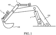
- the fluid pressure control device 100 used for a construction machine, in particular, for a hydraulic excavator (see Fig. 1 ) and provided in a fluid pressure control system 101 which is configured to control a flow of a working fluid supplied to and discharged from fluid pressure actuators will be described as an example.
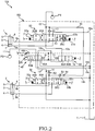
- the fluid pressure control system 101 includes first and second pumps P1 and P2 configured to discharge working oil which serves as the working fluid, a tank T in which the working oil is stored, a first hydraulic cylinder (fluid pressure cylinder) 1 serving as a first actuator configured to drive an object to be driven such as a boom 102, an arm 103, or a bucket 104 (see Fig. 1 ), a second hydraulic cylinder (fluid pressure cylinder) 2 serving as a second actuator configured to drive a spare attachment (not shown), and the fluid pressure control device 100 configured to control actions of the first hydraulic cylinder 1 and the second hydraulic cylinder 2.
- a case where the first hydraulic cylinder 1 drives the boom 102 will be described as an example, and hydraulic cylinders configured to drive the objects to be driven other than the boom 102 will not be described in detail.
- the first pump P1 and the second pump P2 are respectively driven by an engine (not shown) or a motor (not shown) and discharge the working oil.
- the first hydraulic cylinder 1 and the second hydraulic cylinder 2 have the same configurations as each other. Therefore, hereinafter, the configurations of the first hydraulic cylinder 1 will be specifically described, and the configurations of the second hydraulic cylinder 2 will be given the same reference signs as the corresponding configurations of the first hydraulic cylinder 1 and will not be described in detail.
- the first hydraulic cylinder 1 is a double-acting type cylinder having a piston 4 configured to define the inside of a cylinder tube 3 into a rod-side chamber 6 and a bottom side chamber 7.
- a piston rod 5 is coupled to the piston 4.
- the working oil is supplied to and discharged from the rod-side chamber 6 of the first hydraulic cylinder 1 through a first rod side passage 8a.
- the working oil is supplied to and discharged from the bottom side chamber 7 of the first hydraulic cylinder 1 through a first bottom side passage 9a.
- the working oil is supplied to and discharged from a rod-side chamber 6 of the second hydraulic cylinder 2 through a second rod side passage 8b.
- the working oil is supplied to and discharged from a bottom side chamber 7 of the second hydraulic cylinder 2 through a second bottom side passage 9b.
- the first hydraulic cylinder 1 By supplying the working oil to the bottom side chamber 7 and discharging the working oil from the rod-side chamber 6, the first hydraulic cylinder 1 extends and lifts the boom 102. On the contrary, by supplying the working oil to the rod-side chamber 6 and discharging the working oil from the bottom side chamber 7, the first hydraulic cylinder 1 contracts and lowers the boom 102.
- the bottom side chamber 7 is a load side pressure chamber to which self-weight of the boom 102 is applied
- the rod-side chamber 6 is an anti-load side pressure chamber. Therefore, by letting the bottom side chamber 7 serving as the load side pressure chamber communicate with the tank T, the first hydraulic cylinder 1 can also contract by the self-weight of the boom 102.
- the actions of the first hydraulic cylinder 1 and the second hydraulic cylinder 2 will be described in detail later.
- the fluid pressure control device 100 controls a flow of the working oil discharged from the first pump P1 and the second pump P2 and controls extension and contraction of the first hydraulic cylinder 1 and the second hydraulic cylinder 2.
- the first hydraulic cylinder 1 extends and contracts by supplying the working oil discharged from the first pump P1.
- the second hydraulic cylinder 2 extends and contracts by selectively supplying the working oil discharged from the first pump P1 or the second pump P2.
- the fluid pressure control device 100 includes a first pump passage 10 through which the working oil discharged from the first pump P1 is led, a second pump passage 11 through which the working oil discharged from the second pump P2 is led, a main passage 12 to which the working oil discharged from the first pump P1 or the second pump P2 is selectively led, a first control valve 20 provided in the first pump passage 10 and configured to control a flow of the working oil which is supplied to and discharged from the first hydraulic cylinder 1, a second control valve 30 provided in the main passage 12 and configured to control the flow of the working oil which is supplied to and discharged from the second hydraulic cylinder 2, and a switching valve 40 provided in the main passage 12 and configured to selectively switch between the first pump passage 10 and the second pump passage 11 as a passage communicating with the main passage 12.
- Each of the first control valve 20 and the second control valve 30 has a spool (not shown) and serves as a spool valve whose position is switched by moving the spool.
- the first control valve 20 has a pair of pilot chambers 21a, 21b and springs 22a, 22b serving as biasing members, and is actuated in accordance with a pressure difference between the pair of pilot chambers 21a, 21b.
- the first pump passage 10, a first branch passage 13 branching from the first pump passage 10 on the upstream of the first control valve 20 (on the first pump P1 side), a first tank passage 16a communicating with the tank T, and the first rod side passage 8a and the first bottom side passage 9a respectively connected to the first hydraulic cylinder 1 are connected to the first control valve 20.
- a first check valve 81 configured to allow a flow of the working oil running from the first pump P1 toward the first control valve 20 and restricts a reverse flow is provided in the first branch passage 13.
- the first control valve 20 has a first neutral position 20A at which the first pump passage 10 is opened, and a first extension position 20B and a first contraction position 20C at which the working oil led from the first pump passage 10 is led to the first hydraulic cylinder 1 through the first branch passage 13.
- the first control valve 20 In a state where pilot pressure is not led to the pair of pilot chambers 21a, 21b of the first control valve 20, the first control valve 20 is held at the first neutral position 20A by the pair of springs 22a, 22b. At the first neutral position 20A, the first rod side passage 8a, the first bottom side passage 9a, the first branch passage 13, and the first tank passage 16a are respectively shut off. Therefore, the first hydraulic cylinder 1 does not extend and contract and is maintained in a load holding state.
- the first control valve 20 When the pilot pressure is led to the pilot chamber 21a of the first control valve 20, the first control valve 20 is switched to the first extension position 20B.
- the first branch passage 13 and the first bottom side passage 9a communicate with each other, and the first tank passage 16a and the first rod side passage 8a communicate with each other.
- the first pump passage 10 is shut off. Therefore, when the first control valve 20 is switched to the first extension position 20B, the working oil discharged from the first pump P1 is supplied to the bottom side chamber 7, and the working oil of the rod-side chamber 6 is discharged to the tank T. Thereby, the first hydraulic cylinder 1 extends.
- the first control valve 20 When the pilot pressure is led to the other pilot chamber 21b of the first control valve 20, the first control valve 20 is switched to the first contraction position 20C.
- the first contraction position 20C At the first contraction position 20C, the first branch passage 13 and the first rod side passage 8a communicate with each other, and the first tank passage 16a and the first bottom side passage 9a communicate with each other.
- the first pump passage 10 is opened via a pump restrictor 23 configured to apply resistance to a flow of the working oil passing therethrough.
- the first control valve 20 is switched to the first contraction position 20C, the bottom side chamber 7 communicates with the tank T.
- the first hydraulic cylinder 1 contracts by discharge pressure supplied from the first pump P1 to the rod-side chamber 6 or a load of the boom 102.
- the first contraction position 20C corresponds to a driving position.
- a flow passage allowing communication between the first branch passage 13 and the first rod side passage 8a serves as a "first communication passage 27”
- a flow passage allowing communication between the first tank passage 16a and the first bottom side passage 9a serves as a "second communication passage 28”.
- a rod side restrictor 24 and a bottom side restrictor 25 are provided in the first control valve 20 as restrictors configured to apply resistance to the flow of the working oil passing therethrough.
- the rod side restrictor 24 is provided in the first communication passage 27.
- the bottom side restrictor 25 has a first restrictor 25a and a second restrictor 25b provided in the second communication passage 28 in series with respect to each other, and a third restrictor 25c provided in parallel to the first restrictor 25a and the second restrictor 25b.
- the first communication passage 27 and the second communication passage 28 communicate with each other through a third communication passage 29.
- the third communication passage 29 communicates with the second communication passage 28 in a flow passage between the first restrictor 25a and the second restrictor 25b.
- An inside check valve 85 configured to allow only a flow of the working oil running from the second communication passage 28 toward the first communication passage 27 is provided in the third communication passage 29.
- the second control valve 30 has a pair of pilot chambers 31a, 31b and springs 32a, 32b serving as biasing members, and is actuated in accordance with a pressure difference between the pair of pilot chambers 31a, 31b.
- the second control valve 30 is provided in the main passage 12 to which the working oil discharged from the first pump P1 or the second pump P2 is led, the main passage communicating with the tank T.
- the main passage 12, a second branch passage 14 serving as a supply passage branching from the main passage 12 on the upstream of the second control valve 30, a second tank passage 16b communicating with the tank T, and the second rod side passage 8b and the second bottom side passage 9b respectively connected to the second hydraulic cylinder 2 are connected to the second control valve 30.
- the working oil discharged from the first pump P1 is led to the second control valve 30.
- a second check valve 82 configured to allow a flow of the working oil running from the main passage 12 toward the second control valve 30 and restrict a reverse flow is provided in the second branch passage 14.
- the working oil led by the parallel passage 15 is restricted from being led to the main passage 12.
- a third check valve 83 configured to allow a flow of the working oil running from the first pump passage 10 toward the second branch passage 14 and restrict a reverse flow is provided in the parallel passage 15.
- a restrictor 84 configured to apply resistance to the flow of the working oil passing therethrough is provided in the parallel passage 15 on the upstream side of the third check valve 83 (on the first pump P1 side).
- the second control valve 30 has a second neutral position 30A at which the main passage 12 is opened, and a second extension position 30B and a second contraction position 30C serving as supply positions at which the working oil discharged from the first pump P1 or the second pump P2 is supplied to the second hydraulic cylinder 2.
- the second control valve 30 In a state where the pilot pressure is not led to the pair of pilot chambers 31a, 31b of the second control valve 30, the second control valve 30 is held at the second neutral position 30A by the pair of springs 32a, 32b. At the second neutral position 30A, the second branch passage 14, the second rod side passage 8b, the second bottom side passage 9b, and the second tank passage 16b are respectively shut off. Therefore, the second hydraulic cylinder 2 does not extend and contract and is maintained in a load holding state.
- the second control valve 30 When the pilot pressure is led to the pilot chamber 31a of the second control valve 30, the second control valve 30 is switched to the second extension position 30B.
- the second extension position 30B At the second extension position 30B, the second branch passage 14 and the second bottom side passage 9b communicate with each other, and the second tank passage 16b and the second rod side passage 8b communicate with each other.
- the main passage 12 At the first extension position 20B, the main passage 12 is shut off. Therefore, when the second control valve 30 is switched to the second extension position 30B, the working oil discharged from the first pump P1 or the second pump P2 is supplied to the bottom side chamber 7 through the second branch passage 14, and the working oil of the rod-side chamber 6 is discharged to the tank T. Thereby, the second hydraulic cylinder 2 extends.
- the second control valve 30 When the pilot pressure is led to the other pilot chamber 31b of the second control valve 30, the second control valve 30 is switched to the second contraction position 30C.
- the second contraction position 30C At the second contraction position 30C, the second branch passage 14 and the second rod side passage 8b communicate with each other, and the second tank passage 16b and the second bottom side passage 9b communicate with each other.
- the main passage 12 At the second extension position 30B, the main passage 12 is shut off. Therefore, when the second control valve 30 is switched to the second contraction position 30C, the working oil discharged from the first pump P1 or the second pump P2 is supplied to the rod-side chamber 6 through the second branch passage 14, and the working oil of the bottom side chamber 7 is discharged to the tank T. Thereby, the second hydraulic cylinder 2 contracts.
- the switching valve 40 has a spool (see Fig. 4 ) and serves as a two-position spool valve whose position is switched by moving the spool.
- the spool of the switching valve 40 will be called a "first spool 41".
- the switching valve 40 is connected to the first pump passage 10 through which the working oil discharged from the first pump P1 is led, the second pump passage 11 through which the working oil discharged from the second pump P2 is led, the main passage 12 through which the working oil is led to the second control valve 30 (second hydraulic cylinder 2), and a third tank passage 16c and a fourth tank passage 16d respectively communicating with the tank T.
- the switching valve 40 has a first switching position 40A at which the first pump passage 10 and the main passage 12 communicate with each other and the second pump passage 11 and the third tank passage 16c communicate with each other, and a second switching position 40B at which the second pump passage 11 and the main passage 12 communicate with each other and the first pump passage 10 and the fourth tank passage 16d communicate with each other.
- the switching valve 40 is switched to the first switching position 40A, the working oil discharged from the first pump P1 is led to the second control valve 30 through the main passage 12.
- the switching valve 40 is switched to the second switching position 40B, the working oil discharged from the second pump P2 is led to the second control valve 30 through the main passage 12. Therefore, by switching the position of the switching valve 40, it is possible to select whether the working oil is led to the second control valve 30 from the first pump P1 or the working oil is led to the second control valve 30 from the second pump P2.
- the switching valve 40 has a first spring 51 serving as a first biasing member configured to bias the first spool 41 so that the switching valve 40 is placed at the first switching position 40A, and a switching portion 55 configured to move the first spool 41 against biasing force of the first spring 51 by a manual operation of an operator and switch to the second switching position 40B. Specific configurations and operations of the switching valve 40 will be described in detail later.
- the fluid pressure control device 100 further includes a bypass cut valve 60 provided in the first pump passage 10 on the downstream of the first control valve 20 and on the upstream of the switching valve 40 (between the first control valve 20 and the switching valve 40).
- the bypass cut valve 60 has a spool (see Fig. 4 ) and serves as a two-position spool valve whose position is switched by moving the spool.
- the spool of the bypass cut valve 60 will be called a "second spool 61".
- the bypass cut valve 60 has an open position 60A at which the first pump passage 10 is opened, and a shut-off position 60B at which the first pump passage 10 is shut off.
- the bypass cut valve 60 has a second spring 71 serving as a second biasing member configured to bias the second spool 61 so that the bypass cut valve 60 is placed at the open position 60A, and a pilot chamber 78 to which pilot pressure that biases the second spool 61 against biasing force of the second spring 71 is led. Specific configurations and operations of the bypass cut valve 60 will be described in detail later.
- the switching valve 40 by switching the position of the switching valve 40, switching is made between an action of also driving the second hydraulic cylinder 2 by the first pump P1 configured to supply the working oil to the first hydraulic cylinder 1, and an action of driving the first hydraulic cylinder 1 by the first pump P1 and driving the second hydraulic cylinder 2 by the second pump P2.
- the switching valve 40 is placed at the first switching position 40A and a case where the switching valve 40 is placed at the second switching position 40B will be respectively described.
- the switching valve 40 is switched to the first switching position 40A.
- the switching valve 40 is placed at the first switching position 40A, the first pump passage 10 and the main passage 12 communicate with each other, and the working oil discharged from the first pump P1 is led to the second control valve 30.
- the second control valve 30 is switched to the second neutral position 30A by the pair of springs 32a, 32b.
- the bypass cut valve 60 is switched to the open position 60A.
- the pilot pressure is led to the pilot chamber 21a of the first control valve 20.
- the first control valve 20 is switched to the first extension position 20B.
- the working oil discharged from the first pump P1 is led to the bottom side chamber 7 of the first hydraulic cylinder 1 through the first pump passage 10, the first branch passage 13, and the first bottom side passage 9a.
- the working oil of the rod-side chamber 6 of the first hydraulic cylinder 1 is discharged to the tank T from the first rod side passage 8a through the first tank passage 16a. Thereby, the first hydraulic cylinder 1 extends.
- the first control valve 20 When the first control valve 20 is switched to the first contraction position 20C, the first branch passage 13 and the first rod side passage 8a communicate with each other, and the first pump passage 10 is opened via the pump restrictor 23.
- the main passage 12 is opened by the second control valve 30 and communicates with the tank T. Therefore, the first pump passage 10 communicates with the tank T through the main passage 12, and the discharge pressure of the first pump P1 is not led to the rod-side chamber 6. Meanwhile, in the first hydraulic cylinder 1 configured to drive the boom 102, the self-weight of the boom 102 is applied to the bottom side chamber 7.
- the bottom side chamber 7 contracts not by the discharge pressure of the first pump P1 but by the load of the boom 102, and the working oil of the bottom side chamber 7 is discharged to the tank T through the first bottom side passage 9a and the first tank passage 16a.
- the working oil is supplied to the rod-side chamber 6 through the first branch passage 13 following an increase in capacity. In this way, the first hydraulic cylinder 1 contracts by the load of the boom 102.
- the working oil discharged from the bottom side chamber 7 at the time of contraction of the first hydraulic cylinder 1 is led to the tank T through the first restrictor 25a, the second restrictor 25b, and the third restrictor 25c provided in the second communication passage 28 of the first control valve 20 (see Fig. 3 ). Therefore, the first hydraulic cylinder 1 contracts at speed corresponding to resistance applied by the first restrictor 25a, the second restrictor 25b, and the third restrictor 25c. Thus, by adjusting the resistance applied by the first restrictor 25a, the second restrictor 25b, and the third restrictor 25c, it is possible to adjust the speed of contraction of the first hydraulic cylinder 1.
- the resistance applied by the first restrictor 25a, the second restrictor 25b, and the third restrictor 25c it is also possible to regenerate the working oil discharged from the bottom side chamber 7 to the first communication passage 27 through the second communication passage 28 and the third communication passage 29.
- flow passage resistance (opening degrees) of the first restrictor 25a and the third restrictor 25c it is possible to adjust a ratio between a flow rate (bleed flow rate) of the working oil discharged to the tank T and a flow rate (regeneration flow rate) regenerated to the first communication passage 27 in the working oil discharged from the bottom side chamber 7 of the first hydraulic cylinder 1.
- the ratio of the regeneration flow rate is increased in accordance with a difference between the opening degrees.
- the opening degree of the first restrictor 25a is smaller than the opening degree of the third restrictor 25c
- the ratio of the bleed flow rate is increased in accordance with the difference between the opening degrees.
- the first control valve 20 is switched to the first neutral position 20A by the pair of springs 22a, 22b.
- the bypass cut valve 60 is switched to the open position 60A.
- the working oil discharged from the first pump P1 is led to the main passage 12 through the first pump passage 10 and the parallel passage 15.
- a case where the first hydraulic cylinder 1 extends in the double action is basically the same as the case where the first hydraulic cylinder 1 singly extends, and hence will not be described in detail.
- the second control valve 30 is switched to the second extension position 30B or the second contraction position 30C. Therefore, in a case where the first hydraulic cylinder 1 contracts in the double action, and when the first control valve 20 is switched to the first contraction position 20C, communication between the main passage 12 and the tank T is shut off by the second control valve 30. Thus, in a case where the first hydraulic cylinder 1 contracts in the double action, the discharge pressure of the first pump P1 is led to the rod-side chamber 6 and the first hydraulic cylinder 1 contracts by the discharge pressure of the first pump P1.
- the bypass cut valve 60 is placed at the open position 60A
- the second control valve 30 is placed at the second neutral position 30A
- the first control valve 20 is placed at the first contraction position 20C
- the first pump passage 10 communicates with the tank T
- the first hydraulic cylinder 1 contracts by the load (self-weight) of the boom 102.
- Such contraction of the first hydraulic cylinder 1 by the load of the boom 102 is performed in a state where the bucket 104 is not grounded.
- the pilot pressure is led to the pilot chamber 78 of the bypass cut valve 60 by an operation of the operation lever of the operator.
- the bypass cut valve 60 is switched to the shut-off position 60B, and the first pump passage 10 is shut off. Therefore, in a state where the bypass cut valve 60 is placed at the shut-off position 60B and even when the first control valve 20 is switched to the first contraction position 20C, the first pump passage 10 does not communicate with the tank T.
- the discharge pressure of the first pump P1 is led to the rod-side chamber 6 of the first hydraulic cylinder 1 through the first branch passage 13 and the first rod side passage 8a.
- the first hydraulic cylinder 1 contracts by the discharge pressure of the first pump P1, and hence exerts thrust force to lift the body of the hydraulic excavator. In this way, the jack lifting action is performed.
- the switching valve 40 is switched to the second switching position 40B and the working oil discharged from the second pump P2 is led to the second control valve 30
- the switching valve 40 is switched to the second switching position 40B
- the second pump passage 11 and the main passage 12 communicate with each other
- the first pump passage 10 communicates with the tank T through the fourth tank passage 16d.
- the switching valve 40 is placed at the first switching position 40A and the second control valve 30 is placed at the second neutral position 30A
- the first pump passage 10 also communicates with the tank T.
- the switching valve 40 In a case where the switching valve 40 is placed at the second switching position 40B, the working oil discharged from the second pump P2 is led to the second branch passage 14 through the main passage 12. In a case where the switching valve 40 is placed at the second switching position 40B, the first pump passage 10 communicates with the tank T. Thus, the parallel passage 15 also communicates with the tank T. Therefore, the working oil discharged from the first pump P1 is not led but only the working oil discharged from the second pump P2 is led to the second branch passage 14.
- the switching valve 40 In a case where the switching valve 40 is placed at the second switching position 40B, and when the first control valve 20 is switched to the first contraction position 20C, the first pump passage 10 communicates with the tank T through the pump restrictor 23. Therefore, the working oil discharged from the first pump P1 is not led to the parallel passage 15 and only the working oil discharged from the second pump P2 is led to the second branch passage 14.
- the discharge pressure of the second pump P2 led to the second branch passage 14 becomes larger than the discharge pressure of the first pump P1 led to the parallel passage 15.
- the third check valve 83 is not opened and the working oil passing through the parallel passage 15 is restricted from being led to the second branch passage 14. That is, since the third check valve 83 is not opened, only the working oil discharged from the second pump P2 is led to the second branch passage 14.
- the second hydraulic cylinder 2 is driven by the working oil discharged from the first pump P1 both in the case where the second hydraulic cylinder 2 is singly driven and the case where the double action is performed.
- the switching valve 40 is placed at the second switching position 40B, the second hydraulic cylinder 2 is driven by the working oil discharged from the second pump P2 both in the case where the second hydraulic cylinder 2 is singly driven and the case where the double action is performed.
- the spare attachment driven by the second hydraulic cylinder 2 is different in accordance with the type of the hydraulic excavator in which the fluid pressure control device 100 is installed. In a case where large thrust force is required for driving the spare attachment, there is a need for enlarging the second hydraulic cylinder 2. In a case where the working oil of the first pump P1 is led both to the first hydraulic cylinder 1 and the second hydraulic cylinder 2, a flow rate of the working oil supplied to one of the first hydraulic cylinder 1 and the second hydraulic cylinder 2 is varied by an action of the other hydraulic cylinder.
- the fluid pressure control device 100 by switching the position of the switching valve 40 by the manual operation, it is possible to select whether the working oil is led to the second hydraulic cylinder 2 from the first pump P1 or the working oil is led to the second hydraulic cylinder 2 from the second pump P2 in accordance with the type of the hydraulic excavator or needs of a user. It is possible to select the pump configured to supply the working oil to the second hydraulic cylinder 2 by switching the switching valve 40. Thus, in a case where the user drives the second hydraulic cylinder 2 by any pump, it is possible to share a pipe structure of the fluid pressure control device 100. Therefore, it is possible to reduce manufacturing cost of the fluid pressure control device 100.
- the bypass passage 15 branching from the first pump passage 10 is connected to the second branch passage 14.
- the second branch passage 14 does not communicate with the tank T when the second control valve 30 is placed at any position.
- the third check valve 83 is closed by the discharge pressure of the second pump P2.
- the discharge pressure of the first pump P1 is not led to the second control valve. Therefore, at the time of letting the first hydraulic cylinder 1 extend in a case where the switching valve 40 is placed at the second switching position 40B, the working oil discharged from the first pump P1 is not led to the tank T or other devices through the bypass passage 15 irrespective of the position of the second control valve 30.
- the fluid pressure control device 100 at the time of placing the switching valve 40 at the second switching position 40B and making the first hydraulic cylinder 1 and the second hydraulic cylinder 2 independent from each other, it is possible to lead all the working oil discharged from the first pump P1 to the first hydraulic cylinder 1 and let the first hydraulic cylinder 1 extend. That is, in the fluid pressure control device 100, at the time of switching the switching valve 40 to the second switching position 40B, it is also possible to effectively utilize the working oil discharged from the first pump P1.
- the switching valve 40 when the switching valve 40 is placed at the first switching position 40A, communication between the bypass passage 15 and the tank T is shut off or the working oil is led to the second hydraulic cylinder 2 through the bypass passage 15. Therefore, at the time of placing the switching valve 40 at the first switching position 40A, it is also possible to effectively utilize the working oil discharged from the first pump P1.
- the fluid pressure control device 100 includes a housing 90 configured to accommodate the switching valve 40 and the bypass cut valve 60.
- An accommodation hole 91 serving as a through hole whose ends are open on end surfaces 90a, 90b of the housing 90 is formed in the housing 90.
- the accommodation hole 91 is formed as a through hole whose inner diameter is uniform.
- the first pump passage 10, the second pump passage 11, the main passage 12, the third tank passage 16c, and the fourth tank passage 16d are formed in the housing 90, and respectively opened on an inner peripheral surface of the accommodation hole 91 through annular ports (reference signs are not shown). Further, in the housing 90, an annular drain port 18a communicating with the tank T is formed and opened on the inner peripheral surface of the accommodation hole 91.
- an upstream passage 10a a portion of the first pump passage 10 on the upstream side of the bypass cut valve 60
- a portion of the first pump passage 10 on the downstream side will be called a "downstream passage 10b".
- the switching valve 40 has the first spool 41 slidably inserted into the accommodation hole 91.
- the bypass cut valve 60 has the second spool 61 slidably inserted into the accommodation hole 91.
- the first spool 41 of the switching valve 40 and the second spool 61 of the bypass cut valve 60 are coaxially accommodated in the accommodation hole 91 while opposing each other.
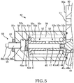
- the switching valve 40 has a first cap 50 attached to the end surface 90a of the housing 90 and configured to seal one opening of the accommodation hole 91, the first spring 51 provided in the first cap 50 and configured to bias the first spool 41 in the direction in which the first spool 41 is separated from the second spool 61 (leftward in the figure), a pair of first spring seats 52, 53 serving as a pair of first seating members on which both ends of the first spring 51 are seated, the first seating members being configured to relatively move following extension and contraction of the first spring 51, the switching portion 55 attached to the first cap 50 and configured to move the first spool 41 against the biasing force of the first spring 51 by the manual operation, an inner pressure chamber 58 formed inside the first cap 50, and an introduction port 50c formed in the first cap 50, the introduction port through which the pilot pressure is led to the inner pressure chamber 58.
- the first spool 41 has a first main body portion 42 configured to be brought into sliding contact with the inner peripheral surface of the accommodation hole 91, and a first support portion 46 attached to one end (left end in the figure) of the first main body portion 42.
- the first main body portion 42 has a first land portion 42a, a second land portion 42b, and a third land portion 42c respectively configured to be brought into sliding contact with the inner peripheral surface of the accommodation hole 91 and placed in line with each other in the axial direction.
- a first annular groove 43a is formed on an outer peripheral surface between the first land portion 42a and the second land portion 42b, and a second annular groove 43b is formed on an outer peripheral surface between the second land portion 42b and the third land portion 42c.
- a first small diameter portion 44 whose outer diameter is smaller than an inner diameter of the accommodation hole 91, and a second small diameter portion 45 provided on the one end side of the first small diameter portion 44 (first support portion 46 side or left side in the figure), the second small diameter portion whose outer diameter is smaller than the first small diameter portion 44 are formed in one end of the first main body portion 42.
- An annular space 43c is formed between the first small diameter portion 44 and the accommodation hole 91.
- the second small diameter portion 45 corresponds to a first projecting portion configured to project from the first small diameter portion 44 toward the first support portion 46 in the axial direction and to be abutted with the first support portion 46.
- the first support portion 46 is accommodated inside the first cap 50.
- the first support portion 46 has a first shaft portion 47 having a screw portion 47a configured to be screwed to the second small diameter portion 45 in one end of the first main body portion 42, and a first head portion 48 whose outer diameter is larger than the first shaft portion 47.
- the first support portion 46 is detachably attached to the first main body portion 42 by screwing the screw portion 47a of the first shaft portion 47.
- the first shaft portion 47 has an outer diameter substantially identical to the second small diameter portion 45 of the first main body portion 42 and is coaxially attached to the second small diameter portion 45.
- a slit 48a extending in the radial direction is formed on an end surface of the first head portion 48.
- a first large diameter hole 50a communicating with the accommodation hole 91, the first large diameter hole into which the first spool 41 can move, a first small diameter hole 50b communicating with the first large diameter hole 50a, the first small diameter hole whose inner diameter is smaller than the first large diameter hole 50a, and the introduction port 50c communicating with the first large diameter hole 50a are formed in the first cap 50.
- the inner pressure chamber 58 is formed by the first small diameter hole 50b and the first large diameter hole 50a.
- the first head portion 48 of the first support portion 46 moves into the first small diameter hole 50b.
- the first spring 51 is provided in an outer periphery of the first shaft portion 47 of the first support portion 46, and both ends of the first spring 51 are supported by the pair of first spring seats 52, 53.
- the first spring seat 52 is seated on a level difference surface 50d between the first large diameter hole 50a and the first small diameter hole 50b, and the other first spring seat 53 is seated on the end surface 90a of the housing 90 to which the first cap 50 is attached.
- the first spring seat 52 follows extension and contraction of the first spring 51 (movement of the first spool 41), the first spring seat 52 relatively move with respect to the other first spring seat 53 along the axial direction of the first spool 41.
- the first spring 51 is placed between the pair of first spring seats 52, 53 in a compressed state.
- the first spring 51 exerts the biasing force that moves the first spool 41 so that the switching valve 40 is placed at the first switching position 40A (in other words, the first spool 41 is separated from the second spool 61 of the bypass cut valve 60).
- the pair of first spring seats 52, 53 is formed in the identical shape to each other.
- the first spring seat 52 has a disc plate shaped flange portion 52a in contact with the level difference surface 50d between the first large diameter hole 50a and the first small diameter hole 50b of the first cap 50, and a tubular boss portion 52b extending in the axial direction from the flange portion 52a toward the other first spring seat 53.
- One end of the first spring 51 is seated on the flange portion 52a.
- the boss portion 52b is inserted into the first spring 51 and supports an inner periphery of the first spring 51.
- An inner diameter of the flange portion 52a is formed to be smaller than an outer diameter of the first head portion 48.
- a slit 52c extending in the radial direction is formed on an end surface of the flange portion 52a in contact with the level difference surface 50d between the first large diameter hole 50a and the first small diameter hole 50b.
- the other first spring seat 53 has a disc plate shaped flange portion 53a in contact with the end surface 90a of the housing 90, and a tubular boss portion 53b extending in the axial direction from the flange portion 53a toward the first spring seat 52.
- the other end of the first spring 51 is seated on the flange portion 53a.
- the boss portion 53b is inserted into the first spring 51 and supports the inner periphery of the first spring 51.
- a slit 53c extending in the radial direction is formed on an end surface of the flange portion 53a in contact with the end surface 90a of the housing 90.
- the switching portion 55 has a switching bolt 56 configured to be screwed into a screw hole 50e which is formed in the first cap 50 and move with respect to the first spool 41 by the manual operation, and a regulating nut 57 configured to regulate a change in a screwing position of the switching bolt 56 with respect to the screw hole 50e.
- the screw hole 50e is formed in the first cap 50 to communicate with the inner pressure chamber 58 (first small diameter hole 50b).
- the switching bolt 56 is provided coaxially with the first support portion 46 of the first spool 41.
- the switching bolt 56 has a screwing portion 56a on which a male thread is formed to be screwed into the screw hole 50e, a contact portion 56b configured to be brought into contact with the first head portion 48 of the first spool 41 from the axial direction, and an operation portion 56c configured to be operated by the operator.
- the contact portion 56b is accommodated in the first small diameter hole 50b.
- Part of the screwing portion 56a projects to the outside of the first cap 50 and an operation portion 56c is provided in an end portion of the projecting screwing portion 56a.
- the regulating nut 57 is screwed to the screwing portion 56a exposed on the outside of the first cap 50.
- the change in the screwing position of the switching bolt 56 with respect to the screw hole 50e of the first cap 50 is regulated.
- the regulating nut 57 and generating a gap between the regulating nut 57 and the first cap 50 it is possible to adjust the screwing position of the switching bolt 56 with respect to the screw hole 50e of the first cap 50, and the switching bolt 56 can move with respect to the first spool 41.
- the bypass cut valve 60 has a second cap 70 attached to the end surface 90b of the housing 90 and configured to seal the other opening of the accommodation hole 91, the second spring 71 provided in the second cap 70 and configured to bias the second spool 61 in the direction in which the second spool 61 is separated from the first spool 41 (rightward in the figure), a pair of second spring seats 72, 73 serving as a pair of second seating members on which both ends of the second spring 71 are seated, the second seating members being configured to relatively move following extension and contraction of the second spring 71, and the pilot chamber 78 formed inside the second cap 70.
- the second spool 61 has a second main body portion 62 configured to be brought into sliding contact with the inner peripheral surface of the accommodation hole 91, and a second support portion 66 attached to one end (right end in the figure) of the second main body portion 62.
- the second main body portion 62 has a fourth land portion 62a, a fifth land portion 62b, a sixth land portion 62c, and a seventh land portion 62d respectively configured to be brought into sliding contact with the inner peripheral surface of the accommodation hole 91 and placed in line with each other in the axial direction.
- a third annular groove 63a is formed on an outer peripheral surface between the fourth land portion 62a and the fifth land portion 62b, and a fourth annular groove 63b is formed on an outer peripheral surface between the fifth land portion 62b and the sixth land portion 62c.
- a fifth annular groove 63c is formed on an outer peripheral surface between the sixth land portion 62c and the seventh land portion 62d.
- the fifth annular groove 63c always communicates with the drain port 18a irrespective of the position of the second spool 61.
- a third small diameter portion 64 whose outer diameter is smaller than the inner diameter of the accommodation hole 91, the third small diameter portion configured to project from the second main body portion 62 in the axial direction is formed in one end portion of the second main body portion 62.
- the third small diameter portion 64 corresponds to a second projecting portion configured to project from the second main body portion 62 toward the second support portion 66 in the axial direction and to be abutted with the second support portion 66.
- the second support portion 66 is accommodated inside the second cap 70.
- the second support portion 66 has a second shaft portion 67 having a screw portion 67a configured to be screwed to the one end portion of the second main body portion 62 of the second spool 61, and a second head portion 68 whose outer diameter is larger than the second shaft portion 67.
- the second support portion 66 is detachably attached to the second main body portion 62 by screwing the screw portion 67a of the second shaft portion 67.
- the second shaft portion 67 has an outer diameter substantially identical to the third small diameter portion 64 of the second main body portion 62 and is coaxially attached to the third small diameter portion 64.
- a second large diameter hole 70a communicating with the accommodation hole 91, the second large diameter hole into which the second spool 61 can move, a second small diameter hole 70b communicating with the second large diameter hole 70a, the second small diameter hole whose inner diameter is smaller than the second large diameter hole 70a, and the pilot port 70c communicating with the second small diameter hole 70b are formed in the second cap 70.
- the pilot chamber 78 is formed by the second small diameter hole 70b and the second large diameter hole 70a.
- the second head portion 68 of the second support portion 66 moves into the second small diameter hole 70b.
- the second spring 71 is provided in an outer periphery of the second shaft portion 67 of the second support portion 66, and both ends of the second spring 71 are supported by the pair of second spring seats 72, 73.
- the second spring seat 72 is seated on a level difference surface 70d between the second large diameter hole 70a and the second small diameter hole 70b of the second cap 70, and the other second spring seat 73 is seated on the other end surface 90b of the housing 90.
- the second spring 71 is placed between the pair of second spring seats 72, 73 in a compressed state.
- the second spring 71 exerts the biasing force that moves the second spool 61 so that the bypass cut valve 60 is placed at the open position 60A (in other words, the second spool 61 is separated from the first spool 41 of the switching valve 40).
- the pair of second spring seats 72, 73 is formed in the identical shape to each other.
- the second spring seat 72 has a disc plate shaped flange portion 72a in contact with the level difference surface 70d between the second large diameter hole 70a and the second small diameter hole 70b of the second cap 70, and a tubular boss portion 72b extending in the axial direction from the flange portion 72a toward the other second spring seat 73.
- An inner diameter of the flange portion 72a is formed to be smaller than an outer diameter of the second head portion 68.
- the other second spring seat 73 has a disc plate shaped flange portion 73a in contact with the end surface 90b of the housing 90, and a tubular boss portion 73b extending in the axial direction from the flange portion 73a toward the second spring seat 72. Both ends of the second spring 71 are respectively seated on the flange portions 72a, 73a of the second spring seats 72, 73, and the boss portions 72b, 73b are respectively inserted into the second spring 71 and support the inner periphery of the second spring 71.
- the first spool 41 and the second spool 61 are separated from each other in the axial direction not to be in contact with each other irrespective of the positions of the switching valve 40 and the bypass cut valve 60.
- An internal space 92 is formed by an end portion of the first spool 41 and an end portion of the second spool 61 in the accommodation hole 91.
- the inner pressure chamber 58 inside the first cap 50 always communicates with the tank T through a drain passage 18.
- the drain passage 18 includes the slit 53c in the first spring seat 53 (see Fig. 5 ), the annular space 43c in an outer periphery of the first small diameter portion 44 in the first spool 41, a first internal passage 49 formed in the first main body portion 42 of the first spool 41, the internal space 92 between the first spool 41 and the second spool 61, a second internal passage 69 formed in the second main body portion 62 of the second spool 61, and the drain port 18a formed in the housing 90.
- a second axial passage 69a passing through the axis of the second main body portion 62, the second axial passage being configured to be opened on an end surface of the second spool 61 which opposes the first spool 41 and communicating with the internal space 92, and a radial passage 69b communicating with the second axial passage 69a, the radial passage being configured to be opened in the fifth annular groove 63c. Since the fifth annular groove 63c always communicates with the drain port 18a irrespective of the position of the second spool 61, the inner pressure chamber 58 in the first cap 50 always communicates with the tank T through the drain passage 18. Since the inner pressure chamber 58 in the first cap 50 always communicates with the tank T, an erroneous action in which the first spool 41 moves by residual pressure in the first cap 50 is prevented.
- the restrictor passage 49b formed in the first main body portion 42 is a restrictor portion configured to apply resistance to the flow of the working oil passing therethrough.
- the restrictor passage 49b is a passage in which the resistance applied to the flow of the working oil is the largest in a flow passage of the working oil from the inner pressure chamber 58 to the drain port 18a.
- the restrictor portion may be formed by an orifice plug, etc. configured to be detachably attached to the drain passage 18.
- the switching valve 40 is switched from the first switching position 40A (state shown in Fig. 4 ) to the second switching position 40B (state shown in Fig. 6 ) by the manual operation, the regulating nut 57 is loosened and the switching bolt 56 is rotated to move toward the first spool 41. Thereby, the first spool 41 is pressed by the switching bolt 56 and moves against the biasing force of the first spring 51. Following movement of the first spool 41 against the biasing force of the first spring 51, the first spring seat 52 is pressed by the first head portion 48 and also moves toward the other first spring seat 53.
- the first spool 41 moves against the biasing force of the first spring 51 until the respective boss portions 52b, 53b of the pair of first spring seats 52, 53 are abutted. In other words, by abutting the pair of first spring seats 52, 53, the movement of the first spool 41 against the biasing force of the first spring 51 is restrected.
- the second pump passage 11 communicates with the main passage 12 through the second annular groove 43b. Communication between the downstream passage 10b of the first pump passage 10 and the main passage 12 is shut off by the second land portion 42b while the downstream passage 10b communicates with the fourth tank passage 16d through the first annular groove 43a.
- the regulating nut 57 is fastened onto the housing 90 and the change in the screwing position of the switching bolt 56 (position of the first spool 41) is regulated. In this way, the switching valve 40 is switched to the second switching position 40B.
- the switching valve 40 is switched from the second switching position 40B (state shown in Fig. 6 ) to the first switching position 40A (state shown in Fig. 4 )
- the regulating nut 57 is loosened and the switching bolt 56 is rotated to be separated from the first spool 41.
- the first spool 41 receives the biasing force of the first spring 51 and moves together with the first spring seat 52 to follow the switching bolt 56 separated from the first spool 41.
- the first spool 41 receives the biasing force of the first spring 51 and moves until the first spring seat 52 is abutted with the level difference surface 50d between the first large diameter hole 50a and the first small diameter hole 50b.
- the manually-operated switching valve needs to be actuated by an external signal such as a case where an operation check is performed by the automatic inspection line together with the fluid pressure control device.
- the inside of the first cap desirably communicates with a tank. Therefore, in general, even when pilot pressure is supplied to the inside of the first cap, the pilot pressure is not applied to the first spool, and it is difficult to move the first spool.
- the restrictor passage 49b is provided in the drain passage 18 through which the working oil of the inner pressure chamber 58 of the first cap 50 is led to the tank T.
- the inner pressure chamber 58 always communicates with the tank T whereas resistance is applied to the working oil passing through the restrictor passage 49b. Therefore, pressure of the inner pressure chamber 58 to which the pilot pressure is led is maintained to be predetermined pressure without lowering to tank pressure by the restrictor passage 49b.
- the position of the switching valve 40 can be switched by the pilot pressure in addition to switching by the manual operation. Since even the manually-operated switching valve 40 can be actuated by an external signal, it is possible to perform the operation check of the switching valve 40 by the automatic inspection line. Thus, it is possible to reduce the man-hour required for the inspection process.
- the switching valve 40 may be actuated by the pilot pressure not only in a case where inspection is implemented in the automatic inspection line but also in other situations.
- the bypass cut valve 60 is held at the open position 60A by the biasing force of the second spring 71 in a state where the pilot pressure is not led to the pilot chamber 78.
- the upstream passage 10a and the downstream passage 10b communicate with each other through the third annular groove 63a and the fourth annular groove 63b of the second spool 61, and the first pump passage 10 is opened.
- the switching valve 40 and the bypass cut valve 60 are respectively the two-position spool valves, it is possible to insert the first spool 41 and the second spool 61 into the single accommodation hole 91 coaxially. Even in this case, the actions of the switching valve 40 and the bypass cut valve 60 do not influence each other. Therefore, in comparison to a case where the first spool 41 and the second spool 61 are respectively inserted into different accommodation holes, it is possible to downsize the housing 90 and it is also possible to reduce cost for processing the accommodation hole 91.
- the first spool 41 of the switching valve 40 and the second spool 61 of the bypass cut valve 60 are inserted into the accommodation hole 91 serving as a through hole whose inner diameter is uniform.
- the internal space 92 is formed between the first spool 41 and the second spool 61.
- a partition wall portion may be provided between the first spool 41 and the second spool 61, and a portion of the accommodation hole 91 in which the first spool 41 is accommodated and a portion of the accommodation hole 91 in which the second spool 61 is accommodated may be partitioned by the partition wall portion.
- a hole allowing communication between the portions of the accommodation hole 91 configured to accommodate the first spool 41 and the second spool 61 is desirably formed in the partition wall portion.
- a restrictor portion may be provided in the partition wall portion.
- the fluid pressure control device 100 by switching the position of the switching valve 40 by the manual operation, it is possible to select whether the working oil is led to the second hydraulic cylinder 2 from the first pump P1 or the working oil is led to the second hydraulic cylinder 2 from the second pump P2 in accordance with the type of the hydraulic excavator or needs of the user. It is possible to select the pump configured to supply the working oil to the second hydraulic cylinder 2 by switching the switching valve 40. Thus, in a case where the user drives the second hydraulic cylinder 2 by any pump, it is possible to share the pipe structure of the fluid pressure control device 100. Therefore, it is possible to reduce the manufacturing cost of the fluid pressure control device 100.
- the first spool 41 of the switching valve 40 and the second spool 61 of the bypass cut valve 60 are inserted into the single accommodation hole 91 while opposing each other. Thereby, it is possible to prevent enlargement of the housing 90 and to reduce the manufacturing cost.
- the restrictor passage 49b serving as the restrictor portion is formed in the drain passage 18.
- the fluid pressure control device 100 includes the first pump passage 10 through which the working oil discharged from the first pump P1 is led, the second pump passage 11 through which the working oil discharged from the second pump P2 is led, the main passage 12 to which the working oil discharged from the first pump P1 or the second pump P2 is selectively led, the main passage communicating with the tank T, the first control valve 20 provided in the first pump passage 10 and configured to control the flow of the working oil which is supplied to and discharged from the first hydraulic cylinder 1, the second control valve 30 provided in the main passage 12 and configured to control the flow of the working oil which is supplied to and discharged from the second hydraulic cylinder 2, the second branch passage 14 branching from the main passage 12, the second branch passage through which the working oil is led to the second control valve 30, the parallel passage 15 branching from the first pump passage 10, the parallel passage being connected to the second branch passage 14, the third check valve 83 provided in the parallel passage 15 and configured to allow only the flow of the working oil running from the first pump P1 toward the second branch passage 14, and the switching valve 40 provided in the main
- the switching valve 40 when the switching valve 40 is placed at the first switching position 40A, the main passage 12 through which the working oil is led to the second control valve 30 communicates with the first pump passage 10, and the working oil discharged from the first pump P1 is led to the second control valve 30. Therefore, the first hydraulic cylinder 1 and the second hydraulic cylinder 2 are respectively actuated by the working oil discharged from the first pump P1.
- the switching valve 40 When the switching valve 40 is placed at the second switching position 40B, the main passage 12 communicates with the second pump passage 11 and the working oil discharged from the second pump P2 is led to the second control valve 30.
- the first hydraulic cylinder 1 is actuated by the working oil discharged from the first pump P1 and the second hydraulic cylinder 2 is actuated by the working oil discharged from the second pump P2 independently from each other.
- the switching valve 40 it is possible to select whether the working oil from the first pump P1 or the working oil from the second pump P2 is led to the second control valve 30. Therefore, irrespective of whether the working oil is led to the second control valve 30 from the first pump P1 or the second pump P2, it is possible to share the pipe structure. Therefore, it is possible to reduce the manufacturing cost of the fluid pressure control device 100.
- the first actuator is a hydraulic cylinder configured to extend and contract by a pressure difference between the bottom side chamber 7 to which the load of the boom 102 is applied and the rod-side chamber 6,
- the first control valve 20 has the first neutral position 20A at which the first pump passage 10 is opened, and the first contraction position 20C at which the first pump passage 10 is opened and the first pump passage 10 and the rod-side chamber 6 communicate with each other
- the second control valve 30 has the second contraction position 30A at which the main passage 12 communicates with the tank T, and the supply position (the second extension position 30B, the second contraction position 30C) at which the working oil led from the second branch passage 14 is supplied to the second hydraulic cylinder 2
- the switching valve 40 allows communication between the second pump passage 11 and the tank T at the first switching position 40A, and allows communication between the first pump passage 10 and the tank T at the second switching position 40B
- the bypass cut valve 60 configured to switch open and shut-off of the first pump passage 10 is provided in the first pump passage 10 on the downstream of the first control valve 20.
- the bypass cut valve 60 opens the first pump passage 10 and the first control valve 20 is placed at the first contraction position 20C in a state where the switching valve 40 is placed at the first switching position 40A and the second control valve 30 is placed at the second neutral position 30A and in a state where the switching valve 40 is placed at the second switching position 40B
- the first pump passage 10 communicates with the tank T.
- the working oil discharged from the first pump P1 is not supplied to the first hydraulic cylinder 1 and the first hydraulic cylinder 1 is actuated by the self-weight of the load.
- the fluid pressure control device 100 further includes the housing 90 configured to accommodate the switching valve 40 and the bypass cut valve 60.
- the switching valve 40 has the first spool 41 configured to switch the position
- the bypass cut valve 60 has the second spool 61 configured to switch the position
- the first spool 41 of the switching valve 40 and the second spool 61 of the bypass cut valve 60 are coaxially accommodated in the accommodation hole 91 formed in the housing 90 while opposing each other.
- the accommodation hole 91 is formed as a through hole whose both ends are open on the end surfaces 90a, 90b of the housing 90
- the switching valve 40 further has the first cap 50 attached to the housing 90 and configured to seal the one opening of the accommodation hole 91, the inner pressure chamber 58 formed in the first cap 50, the first spring 51 provided in the first cap 50 and configured to bias the first spool 41 in the direction in which the first spool 41 is separated from the second spool 61, and the switching portion 55 provided in the first cap 50 and configured to move the first spool 41 against the biasing force of the first spring 51 by the manual operation
- the bypass cut valve 60 further has the second cap 70 attached to the housing 90 and configured to seal the other opening of the accommodation hole 91, the pilot chamber 78 formed in the second cap 70, the pilot chamber to which the pilot pressure that biases the second spool 61 toward the first spool 41 is led through the pilot port 70c, and the second spring 71 provided in the second cap 70 and configured to bias the
- the introduction port 50c through which the pilot pressure that moves the first spool 41 against the biasing force of the first spring 51 is led to the inner pressure chamber 58 is formed in the first cap 50, the inner pressure chamber 58 in the first cap 50 always communicates with the tank T through the drain passage 18, and the restrictor passage 49b configured to apply resistance to the flow of the passing working fluid is provided in the drain passage 18.
- the drain passage 18 has the internal space 92 defined in the accommodation hole 91 by the end portion of the first spool 41 and the end portion of the second spool 61 opposing to each other, the first internal passage 49 formed in the first spool 41, the first internal passage allowing communication between the inner pressure chamber 58 and the internal space 92, and the second internal passage 69 formed in the second spool 61, the second internal passage allowing communication between the internal space 92 and the tank T.
- the switching valve 40 further has the pair of first spring seats 52, 53 on which both the ends of the first spring 51 are seated, the first spring seats being configured to relatively move following extension and contraction of the first spring 51
- the bypass cut valve 60 further has the pair of second spring seats 72, 73 on which both the ends of the second spring 71 are seated, the second spring seats being configured to relatively move following extension and contraction of the second spring 71
- movement of the first spool 41 against the biasing force of the first spring 51 is restricted by abutting the pair of first spring seats 52, 53 with each other
- movement of the second spool 61 against the biasing force of the second spring 71 is restricted by abutting the pair of second spring seats 72, 73 with each other.
- the first spool 41 has the first main body portion 42 configured to be brought into sliding contact with the inner peripheral surface of the accommodation hole 91, and the first support portion 46 attached to the end portion of the first main body portion 42, the first support portion in which the first spring 51 is provided in the outer periphery
- the second spool 61 has the second main body portion 62 configured to be brought into sliding contact with the inner peripheral surface of the accommodation hole 91, and the second support portion 66 attached to the end portion of the second main body portion 62, the second support portion in which the second spring 71 is provided in the outer periphery
- the first main body portion 42 has the second small diameter portion 45 configured to project toward the first support portion 46 in the axial direction and to be abutted with the first support portion 46
- the second main body portion 62 has the third small diameter portion 64 configured to project toward the second support portion 66 in the axial direction and to be abutted with the second support portion 66.
- the accommodation hole 91 is formed as a through hole whose inner diameter is uniform.
Landscapes
- Engineering & Computer Science (AREA)
- Physics & Mathematics (AREA)
- Fluid Mechanics (AREA)
- General Engineering & Computer Science (AREA)
- Mechanical Engineering (AREA)
- Mining & Mineral Resources (AREA)
- Civil Engineering (AREA)
- Structural Engineering (AREA)
- Fluid-Pressure Circuits (AREA)
- Operation Control Of Excavators (AREA)
Abstract
Description
- The present invention relates to a fluid pressure control device.
- As a hydraulic drive device of a construction machine,
JP2012-241803A - This hydraulic drive device further includes a third hydraulic pump configured to supply pressure oil that respectively actuates the boom cylinder and the arm cylinder, a third boom direction control valve connected to the third hydraulic pump and configured to control the flow of the pressure oil supplied to the boom cylinder, a third arm direction control valve connected to the third boom direction control valve in tandem and configured to control the flow of the pressure oil supplied to the arm cylinder, and a second spare direction control valve connected to the third hydraulic pump in parallel to the third boom direction control valve.
- In this hydraulic drive device, by providing a second actuator configured to drive a second specialty attachment connected to an arm and supplying the pressure oil of the third hydraulic pump to the second actuator via the second spare direction control valve, it is possible to drive the second specialty attachment.
- In the hydraulic drive device of
JP2012-241803A - In order to prevent such an unstable action of the actuators,
JP2012-241803A - However, whether a certain control valve (spare direction control valve) is connected to the same pump as the other control valve (boom direction control valve) in parallel or connected to another pump independently from the other control valve depends on the working machine to which the hydraulic drive device is installed, needs, etc.
- Depending on whether or not a certain control valve is connected to the same pump as the other control valve in parallel or made independent, a pump configured to supply the working fluid is different and hence a pipe structure is also different.
- Therefore, in the hydraulic drive device described in
JP2012-241803A - An object of the present invention is to reduce manufacturing cost of a fluid pressure control device.
- According to one aspect of the present invention, a fluid pressure control device includes: a first pump passage through which a working fluid discharged from a first pump is led; a second pump passage through which a working fluid discharged from a second pump is led; a main passage to which the working fluid discharged from the first pump or the second pump is selectively led; a first control valve provided in the first pump passage and configured to control a flow of the working fluid which is supplied to and discharged from a first actuator; a second control valve provided in the main passage and configured to control a flow of the working fluid which is supplied to and discharged from a second actuator; a supply passage branching from the main passage, the working fluid being led to the second control valve through the supply passage; a parallel passage branching from the first pump passage, the parallel passage being connected to the supply passage; a check valve provided in the parallel passage and configured to allow only a flow of the working fluid from the first pump toward the supply passage; and a switching valve provided in the main passage and configured to selectively switch between the first pump passage and the second pump passage as a passage communicating with the main passage The switching valve has: a first switching position at which the first pump passage and the main passage communicate with each other; and a second switching position at which the second pump passage and the main passage communicate with each other.
-
-
Fig. 1 is a configuration diagram showing part of a hydraulic excavator. -
Fig. 2 is a hydraulic circuit diagram showing a fluid pressure control device according to an embodiment of the present invention. -
Fig. 3 is an enlarged view of part of the hydraulic circuit diagram showing the fluid pressure control device according to the embodiment of the present invention. -
Fig. 4 is a sectional view showing a switching valve and a bypass cut valve of the fluid pressure control device according to the embodiment of the present invention, showing a state where the switching valve is placed at a first switching position and the bypass cut valve is placed at an open position. -
Fig. 5 is an enlarged sectional view showing the switching valve of the fluid pressure control device according to the embodiment of the present invention. -
Fig. 6 is a sectional view showing the switching valve and the bypass cut valve of the fluid pressure control device according to the embodiment of the present invention, showing a state where the switching valve is placed at a second switching position and the bypass cut valve is placed at a shut-off position. -
Fig. 7 is a sectional view showing the switching valve and the bypass cut valve of the fluid pressure control device according to the embodiment of the present invention, showing a state where the switching valve is switched to the second switching position by pilot pressure. - Hereinafter, with reference to the drawings, a fluid
pressure control device 100 according to an embodiment of the present invention will be described. Hereinafter, the fluidpressure control device 100 used for a construction machine, in particular, for a hydraulic excavator (seeFig. 1 ) and provided in a fluidpressure control system 101 which is configured to control a flow of a working fluid supplied to and discharged from fluid pressure actuators will be described as an example. - First, with reference to
Fig. 2 , the entire configuration of the fluidpressure control system 101 including the fluidpressure control device 100 will be described. - The fluid
pressure control system 101 includes first and second pumps P1 and P2 configured to discharge working oil which serves as the working fluid, a tank T in which the working oil is stored, a first hydraulic cylinder (fluid pressure cylinder) 1 serving as a first actuator configured to drive an object to be driven such as aboom 102, anarm 103, or a bucket 104 (seeFig. 1 ), a second hydraulic cylinder (fluid pressure cylinder) 2 serving as a second actuator configured to drive a spare attachment (not shown), and the fluidpressure control device 100 configured to control actions of the firsthydraulic cylinder 1 and the secondhydraulic cylinder 2. Hereinafter, a case where the firsthydraulic cylinder 1 drives theboom 102 will be described as an example, and hydraulic cylinders configured to drive the objects to be driven other than theboom 102 will not be described in detail. - The first pump P1 and the second pump P2 are respectively driven by an engine (not shown) or a motor (not shown) and discharge the working oil.
- The first
hydraulic cylinder 1 and the secondhydraulic cylinder 2 have the same configurations as each other. Therefore, hereinafter, the configurations of the firsthydraulic cylinder 1 will be specifically described, and the configurations of the secondhydraulic cylinder 2 will be given the same reference signs as the corresponding configurations of the firsthydraulic cylinder 1 and will not be described in detail. - The first
hydraulic cylinder 1 is a double-acting type cylinder having apiston 4 configured to define the inside of acylinder tube 3 into a rod-side chamber 6 and abottom side chamber 7. Apiston rod 5 is coupled to thepiston 4. The working oil is supplied to and discharged from the rod-side chamber 6 of the firsthydraulic cylinder 1 through a firstrod side passage 8a. The working oil is supplied to and discharged from thebottom side chamber 7 of the firsthydraulic cylinder 1 through a firstbottom side passage 9a. The working oil is supplied to and discharged from a rod-side chamber 6 of the secondhydraulic cylinder 2 through a secondrod side passage 8b. The working oil is supplied to and discharged from abottom side chamber 7 of the secondhydraulic cylinder 2 through a secondbottom side passage 9b. - By supplying the working oil to the
bottom side chamber 7 and discharging the working oil from the rod-side chamber 6, the firsthydraulic cylinder 1 extends and lifts theboom 102. On the contrary, by supplying the working oil to the rod-side chamber 6 and discharging the working oil from thebottom side chamber 7, the firsthydraulic cylinder 1 contracts and lowers theboom 102. In the firsthydraulic cylinder 1 configured to drive theboom 102, thebottom side chamber 7 is a load side pressure chamber to which self-weight of theboom 102 is applied, and the rod-side chamber 6 is an anti-load side pressure chamber. Therefore, by letting thebottom side chamber 7 serving as the load side pressure chamber communicate with the tank T, the firsthydraulic cylinder 1 can also contract by the self-weight of theboom 102. The actions of the firsthydraulic cylinder 1 and the secondhydraulic cylinder 2 will be described in detail later. - Next, the fluid
pressure control device 100 will be described. - The fluid
pressure control device 100 controls a flow of the working oil discharged from the first pump P1 and the second pump P2 and controls extension and contraction of the firsthydraulic cylinder 1 and the secondhydraulic cylinder 2. The firsthydraulic cylinder 1 extends and contracts by supplying the working oil discharged from the first pump P1. The secondhydraulic cylinder 2 extends and contracts by selectively supplying the working oil discharged from the first pump P1 or the second pump P2. Hereinafter, with reference to the hydraulic circuit diagram ofFig. 2 , the entire configuration of the fluidpressure control device 100 will be described. - As shown in
Fig. 2 , the fluidpressure control device 100 includes afirst pump passage 10 through which the working oil discharged from the first pump P1 is led, asecond pump passage 11 through which the working oil discharged from the second pump P2 is led, amain passage 12 to which the working oil discharged from the first pump P1 or the second pump P2 is selectively led, afirst control valve 20 provided in thefirst pump passage 10 and configured to control a flow of the working oil which is supplied to and discharged from the firsthydraulic cylinder 1, asecond control valve 30 provided in themain passage 12 and configured to control the flow of the working oil which is supplied to and discharged from the secondhydraulic cylinder 2, and aswitching valve 40 provided in themain passage 12 and configured to selectively switch between thefirst pump passage 10 and thesecond pump passage 11 as a passage communicating with themain passage 12. - Each of the
first control valve 20 and thesecond control valve 30 has a spool (not shown) and serves as a spool valve whose position is switched by moving the spool. - The
first control valve 20 has a pair ofpilot chambers springs pilot chambers - The
first pump passage 10, afirst branch passage 13 branching from thefirst pump passage 10 on the upstream of the first control valve 20 (on the first pump P1 side), afirst tank passage 16a communicating with the tank T, and the firstrod side passage 8a and the firstbottom side passage 9a respectively connected to the firsthydraulic cylinder 1 are connected to thefirst control valve 20. Afirst check valve 81 configured to allow a flow of the working oil running from the first pump P1 toward thefirst control valve 20 and restricts a reverse flow is provided in thefirst branch passage 13. - The
first control valve 20 has a firstneutral position 20A at which thefirst pump passage 10 is opened, and afirst extension position 20B and afirst contraction position 20C at which the working oil led from thefirst pump passage 10 is led to the firsthydraulic cylinder 1 through thefirst branch passage 13. - In a state where pilot pressure is not led to the pair of
pilot chambers first control valve 20, thefirst control valve 20 is held at the firstneutral position 20A by the pair ofsprings neutral position 20A, the firstrod side passage 8a, the firstbottom side passage 9a, thefirst branch passage 13, and thefirst tank passage 16a are respectively shut off. Therefore, the firsthydraulic cylinder 1 does not extend and contract and is maintained in a load holding state. - When the pilot pressure is led to the
pilot chamber 21a of thefirst control valve 20, thefirst control valve 20 is switched to thefirst extension position 20B. At thefirst extension position 20B, thefirst branch passage 13 and the firstbottom side passage 9a communicate with each other, and thefirst tank passage 16a and the firstrod side passage 8a communicate with each other. At thefirst extension position 20B, thefirst pump passage 10 is shut off. Therefore, when thefirst control valve 20 is switched to thefirst extension position 20B, the working oil discharged from the first pump P1 is supplied to thebottom side chamber 7, and the working oil of the rod-side chamber 6 is discharged to the tank T. Thereby, the firsthydraulic cylinder 1 extends. - When the pilot pressure is led to the
other pilot chamber 21b of thefirst control valve 20, thefirst control valve 20 is switched to thefirst contraction position 20C. At thefirst contraction position 20C, thefirst branch passage 13 and the firstrod side passage 8a communicate with each other, and thefirst tank passage 16a and the firstbottom side passage 9a communicate with each other. At thefirst contraction position 20C, thefirst pump passage 10 is opened via apump restrictor 23 configured to apply resistance to a flow of the working oil passing therethrough. When thefirst control valve 20 is switched to thefirst contraction position 20C, thebottom side chamber 7 communicates with the tank T. Thus, the firsthydraulic cylinder 1 contracts by discharge pressure supplied from the first pump P1 to the rod-side chamber 6 or a load of theboom 102. Thefirst contraction position 20C corresponds to a driving position. - With reference to
Fig. 3 , thefirst contraction position 20C of thefirst control valve 20 will be more specifically described. Hereinafter, at thefirst contraction position 20C, a flow passage allowing communication between thefirst branch passage 13 and the firstrod side passage 8a serves as a "first communication passage 27", and a flow passage allowing communication between thefirst tank passage 16a and the firstbottom side passage 9a serves as a "second communication passage 28". A rod side restrictor 24 and a bottom side restrictor 25 are provided in thefirst control valve 20 as restrictors configured to apply resistance to the flow of the working oil passing therethrough. The rod side restrictor 24 is provided in thefirst communication passage 27. The bottom side restrictor 25 has afirst restrictor 25a and asecond restrictor 25b provided in thesecond communication passage 28 in series with respect to each other, and athird restrictor 25c provided in parallel to thefirst restrictor 25a and thesecond restrictor 25b. - The
first communication passage 27 and thesecond communication passage 28 communicate with each other through athird communication passage 29. Thethird communication passage 29 communicates with thesecond communication passage 28 in a flow passage between thefirst restrictor 25a and thesecond restrictor 25b. Aninside check valve 85 configured to allow only a flow of the working oil running from thesecond communication passage 28 toward thefirst communication passage 27 is provided in thethird communication passage 29. Specific contents to switch thefirst control valve 20 to thefirst contraction position 20C and let the firsthydraulic cylinder 1 contract will be described in detail later. - The
second control valve 30 has a pair ofpilot chambers springs pilot chambers Fig. 2 , thesecond control valve 30 is provided in themain passage 12 to which the working oil discharged from the first pump P1 or the second pump P2 is led, the main passage communicating with the tank T. Themain passage 12, asecond branch passage 14 serving as a supply passage branching from themain passage 12 on the upstream of thesecond control valve 30, asecond tank passage 16b communicating with the tank T, and the secondrod side passage 8b and the secondbottom side passage 9b respectively connected to the secondhydraulic cylinder 2 are connected to thesecond control valve 30. - A
parallel passage 15 branching from thefirst pump passage 10 on the upstream of thefirst control valve 20 joins thesecond branch passage 14. By theparallel passage 15, the working oil discharged from the first pump P1 is led to thesecond control valve 30. Asecond check valve 82 configured to allow a flow of the working oil running from themain passage 12 toward thesecond control valve 30 and restrict a reverse flow is provided in thesecond branch passage 14. By thesecond check valve 82, the working oil led by theparallel passage 15 is restricted from being led to themain passage 12. Athird check valve 83 configured to allow a flow of the working oil running from thefirst pump passage 10 toward thesecond branch passage 14 and restrict a reverse flow is provided in theparallel passage 15. A restrictor 84 configured to apply resistance to the flow of the working oil passing therethrough is provided in theparallel passage 15 on the upstream side of the third check valve 83 (on the first pump P1 side). - The
second control valve 30 has a secondneutral position 30A at which themain passage 12 is opened, and asecond extension position 30B and asecond contraction position 30C serving as supply positions at which the working oil discharged from the first pump P1 or the second pump P2 is supplied to the secondhydraulic cylinder 2. - In a state where the pilot pressure is not led to the pair of
pilot chambers second control valve 30, thesecond control valve 30 is held at the secondneutral position 30A by the pair ofsprings neutral position 30A, thesecond branch passage 14, the secondrod side passage 8b, the secondbottom side passage 9b, and thesecond tank passage 16b are respectively shut off. Therefore, the secondhydraulic cylinder 2 does not extend and contract and is maintained in a load holding state. - When the pilot pressure is led to the
pilot chamber 31a of thesecond control valve 30, thesecond control valve 30 is switched to thesecond extension position 30B. At thesecond extension position 30B, thesecond branch passage 14 and the secondbottom side passage 9b communicate with each other, and thesecond tank passage 16b and the secondrod side passage 8b communicate with each other. At thefirst extension position 20B, themain passage 12 is shut off. Therefore, when thesecond control valve 30 is switched to thesecond extension position 30B, the working oil discharged from the first pump P1 or the second pump P2 is supplied to thebottom side chamber 7 through thesecond branch passage 14, and the working oil of the rod-side chamber 6 is discharged to the tank T. Thereby, the secondhydraulic cylinder 2 extends. - When the pilot pressure is led to the
other pilot chamber 31b of thesecond control valve 30, thesecond control valve 30 is switched to thesecond contraction position 30C. At thesecond contraction position 30C, thesecond branch passage 14 and the secondrod side passage 8b communicate with each other, and thesecond tank passage 16b and the secondbottom side passage 9b communicate with each other. At thesecond extension position 30B, themain passage 12 is shut off. Therefore, when thesecond control valve 30 is switched to thesecond contraction position 30C, the working oil discharged from the first pump P1 or the second pump P2 is supplied to the rod-side chamber 6 through thesecond branch passage 14, and the working oil of thebottom side chamber 7 is discharged to the tank T. Thereby, the secondhydraulic cylinder 2 contracts. - The switching
valve 40 has a spool (seeFig. 4 ) and serves as a two-position spool valve whose position is switched by moving the spool. Hereinafter, the spool of the switchingvalve 40 will be called a "first spool 41". - The switching
valve 40 is connected to thefirst pump passage 10 through which the working oil discharged from the first pump P1 is led, thesecond pump passage 11 through which the working oil discharged from the second pump P2 is led, themain passage 12 through which the working oil is led to the second control valve 30 (second hydraulic cylinder 2), and athird tank passage 16c and afourth tank passage 16d respectively communicating with the tank T. - The switching
valve 40 has afirst switching position 40A at which thefirst pump passage 10 and themain passage 12 communicate with each other and thesecond pump passage 11 and thethird tank passage 16c communicate with each other, and asecond switching position 40B at which thesecond pump passage 11 and themain passage 12 communicate with each other and thefirst pump passage 10 and thefourth tank passage 16d communicate with each other. When the switchingvalve 40 is switched to thefirst switching position 40A, the working oil discharged from the first pump P1 is led to thesecond control valve 30 through themain passage 12. When the switchingvalve 40 is switched to thesecond switching position 40B, the working oil discharged from the second pump P2 is led to thesecond control valve 30 through themain passage 12. Therefore, by switching the position of the switchingvalve 40, it is possible to select whether the working oil is led to thesecond control valve 30 from the first pump P1 or the working oil is led to thesecond control valve 30 from the second pump P2. - The switching
valve 40 has afirst spring 51 serving as a first biasing member configured to bias thefirst spool 41 so that the switchingvalve 40 is placed at thefirst switching position 40A, and a switchingportion 55 configured to move thefirst spool 41 against biasing force of thefirst spring 51 by a manual operation of an operator and switch to thesecond switching position 40B. Specific configurations and operations of the switchingvalve 40 will be described in detail later. - The fluid
pressure control device 100 further includes a bypass cutvalve 60 provided in thefirst pump passage 10 on the downstream of thefirst control valve 20 and on the upstream of the switching valve 40 (between thefirst control valve 20 and the switching valve 40). - The bypass cut
valve 60 has a spool (seeFig. 4 ) and serves as a two-position spool valve whose position is switched by moving the spool. Hereinafter, the spool of the bypass cutvalve 60 will be called a "second spool 61". - The bypass cut
valve 60 has anopen position 60A at which thefirst pump passage 10 is opened, and a shut-offposition 60B at which thefirst pump passage 10 is shut off. The bypass cutvalve 60 has asecond spring 71 serving as a second biasing member configured to bias thesecond spool 61 so that the bypass cutvalve 60 is placed at theopen position 60A, and apilot chamber 78 to which pilot pressure that biases thesecond spool 61 against biasing force of thesecond spring 71 is led. Specific configurations and operations of the bypass cutvalve 60 will be described in detail later. - Next, actions of the fluid
pressure control device 100 will be described. - In the fluid
pressure control device 100, by switching the position of the switchingvalve 40, switching is made between an action of also driving the secondhydraulic cylinder 2 by the first pump P1 configured to supply the working oil to the firsthydraulic cylinder 1, and an action of driving the firsthydraulic cylinder 1 by the first pump P1 and driving the secondhydraulic cylinder 2 by the second pump P2. Hereinafter, a case where the switchingvalve 40 is placed at thefirst switching position 40A and a case where the switchingvalve 40 is placed at thesecond switching position 40B will be respectively described. - First, the case where the switching
valve 40 is switched to thefirst switching position 40A will be described. In a case where the switchingvalve 40 is placed at thefirst switching position 40A, thefirst pump passage 10 and themain passage 12 communicate with each other, and the working oil discharged from the first pump P1 is led to thesecond control valve 30. - In a case where the second
hydraulic cylinder 2 is not driven but the firsthydraulic cylinder 1 is singly driven, thesecond control valve 30 is switched to the secondneutral position 30A by the pair ofsprings valve 60 is switched to theopen position 60A. - In a case where the first
hydraulic cylinder 1 extends, in accordance with an operation of an operation lever (not shown) by the operator, the pilot pressure is led to thepilot chamber 21a of thefirst control valve 20. Thereby, thefirst control valve 20 is switched to thefirst extension position 20B. - When the
first control valve 20 is switched to thefirst extension position 20B, the working oil discharged from the first pump P1 is led to thebottom side chamber 7 of the firsthydraulic cylinder 1 through thefirst pump passage 10, thefirst branch passage 13, and the firstbottom side passage 9a. The working oil of the rod-side chamber 6 of the firsthydraulic cylinder 1 is discharged to the tank T from the firstrod side passage 8a through thefirst tank passage 16a. Thereby, the firsthydraulic cylinder 1 extends. - In a case where the first
hydraulic cylinder 1 contracts, in accordance with an operation of the operation lever by the operator, the pilot pressure is led to theother pilot chamber 21b of thefirst control valve 20. Thereby, thefirst control valve 20 is switched to thefirst contraction position 20C. - When the
first control valve 20 is switched to thefirst contraction position 20C, thefirst branch passage 13 and the firstrod side passage 8a communicate with each other, and thefirst pump passage 10 is opened via thepump restrictor 23. At the time of single contraction of the firsthydraulic cylinder 1, themain passage 12 is opened by thesecond control valve 30 and communicates with the tank T. Therefore, thefirst pump passage 10 communicates with the tank T through themain passage 12, and the discharge pressure of the first pump P1 is not led to the rod-side chamber 6. Meanwhile, in the firsthydraulic cylinder 1 configured to drive theboom 102, the self-weight of theboom 102 is applied to thebottom side chamber 7. Therefore, in this case, thebottom side chamber 7 contracts not by the discharge pressure of the first pump P1 but by the load of theboom 102, and the working oil of thebottom side chamber 7 is discharged to the tank T through the firstbottom side passage 9a and thefirst tank passage 16a. The working oil is supplied to the rod-side chamber 6 through thefirst branch passage 13 following an increase in capacity. In this way, the firsthydraulic cylinder 1 contracts by the load of theboom 102. - The working oil discharged from the
bottom side chamber 7 at the time of contraction of the firsthydraulic cylinder 1 is led to the tank T through thefirst restrictor 25a, thesecond restrictor 25b, and thethird restrictor 25c provided in thesecond communication passage 28 of the first control valve 20 (seeFig. 3 ). Therefore, the firsthydraulic cylinder 1 contracts at speed corresponding to resistance applied by thefirst restrictor 25a, thesecond restrictor 25b, and thethird restrictor 25c. Thus, by adjusting the resistance applied by thefirst restrictor 25a, thesecond restrictor 25b, and thethird restrictor 25c, it is possible to adjust the speed of contraction of the firsthydraulic cylinder 1. - By adjusting the resistance applied by the
first restrictor 25a, thesecond restrictor 25b, and thethird restrictor 25c, it is also possible to regenerate the working oil discharged from thebottom side chamber 7 to thefirst communication passage 27 through thesecond communication passage 28 and thethird communication passage 29. Specifically speaking, by adjusting flow passage resistance (opening degrees) of thefirst restrictor 25a and thethird restrictor 25c, it is possible to adjust a ratio between a flow rate (bleed flow rate) of the working oil discharged to the tank T and a flow rate (regeneration flow rate) regenerated to thefirst communication passage 27 in the working oil discharged from thebottom side chamber 7 of the firsthydraulic cylinder 1. In a case where the opening degree of thefirst restrictor 25a is larger than the opening degree of thethird restrictor 25c, the ratio of the regeneration flow rate is increased in accordance with a difference between the opening degrees. On the contrary, in a case where the opening degree of thefirst restrictor 25a is smaller than the opening degree of thethird restrictor 25c, the ratio of the bleed flow rate is increased in accordance with the difference between the opening degrees. In this way, by mainly adjusting the opening degrees of thefirst restrictor 25a and thethird restrictor 25c, it is possible to adjust the regeneration flow rate and the bleed flow rate. - In a case where the switching
valve 40 is placed at thefirst switching position 40A, and the firsthydraulic cylinder 1 is not driven but the secondhydraulic cylinder 2 is singly driven, thefirst control valve 20 is switched to the firstneutral position 20A by the pair ofsprings valve 60 is switched to theopen position 60A. The working oil discharged from the first pump P1 is led to themain passage 12 through thefirst pump passage 10 and theparallel passage 15. - In a case where the second
hydraulic cylinder 2 extends, in accordance with an operation of the operation lever by the operator, the pilot pressure is led to thepilot chamber 31a of thesecond control valve 30. Thereby, thesecond control valve 30 is switched to thesecond extension position 30B. - When the
second control valve 30 is switched to thesecond extension position 30B, the working oil discharged from the first pump P1 and led to themain passage 12 is led to thebottom side chamber 7 of the secondhydraulic cylinder 2 through the secondbottom side passage 9b. The working oil of the rod-side chamber 6 of the secondhydraulic cylinder 2 is discharged to the tank T from the secondrod side passage 8b through thesecond tank passage 16b. Thereby, the secondhydraulic cylinder 2 extends. - In a case where the second
hydraulic cylinder 2 contracts, in accordance with an operation of the operation lever by the operator, the pilot pressure is led to theother pilot chamber 31b of thesecond control valve 30. Thereby, thesecond control valve 30 is switched to thesecond contraction position 30C. - When the
second control valve 30 is switched to thesecond contraction position 30C, the working oil discharged from the first pump P1 and led through themain passage 12 is led to the rod-side chamber 6 of the secondhydraulic cylinder 2 through the secondrod side passage 8b. The working oil of thebottom side chamber 7 of the secondhydraulic cylinder 2 is discharged to the tank T from the secondbottom side passage 9b through thesecond tank passage 16b. Thereby, the secondhydraulic cylinder 2 contracts. - Next, a double action in which the first
hydraulic cylinder 1 extends and contracts and the secondhydraulic cylinder 2 also extends and contracts will be described. Hereinafter, a case where thefirst control valve 20 is switched to thefirst extension position 20B and the firsthydraulic cylinder 1 extends, and thesecond control valve 30 is switched to thesecond extension position 30B and the secondhydraulic cylinder 2 extends as the double action will be described. - A case where the first
hydraulic cylinder 1 extends in the double action is basically the same as the case where the firsthydraulic cylinder 1 singly extends, and hence will not be described in detail. - When the
first control valve 20 is switched to thefirst extension position 20B, thefirst pump passage 10 is shut off. Therefore, the working oil discharged from the first pump P1 is not led to thesecond branch passage 14 through thefirst pump passage 10 and themain passage 12. Meanwhile, the working oil discharged from the first pump P1 is led to thesecond branch passage 14 through theparallel passage 15. Therefore, the working oil led from theparallel passage 15 to the secondbottom side passage 9b through thesecond branch passage 14 is supplied to thebottom side chamber 7 of the secondhydraulic cylinder 2, and the secondhydraulic cylinder 2 extends. - In this way, in the double action in a case where the switching
valve 40 is placed at thefirst switching position 40A, part of the working oil discharged from the first pump P1 is led to the firsthydraulic cylinder 1 through thefirst pump passage 10, and the remaining working oil discharged from the first pump P1 is led to the secondhydraulic cylinder 2 through theparallel passage 15. - In the double action, the
second control valve 30 is switched to thesecond extension position 30B or thesecond contraction position 30C. Therefore, in a case where the firsthydraulic cylinder 1 contracts in the double action, and when thefirst control valve 20 is switched to thefirst contraction position 20C, communication between themain passage 12 and the tank T is shut off by thesecond control valve 30. Thus, in a case where the firsthydraulic cylinder 1 contracts in the double action, the discharge pressure of the first pump P1 is led to the rod-side chamber 6 and the firsthydraulic cylinder 1 contracts by the discharge pressure of the first pump P1. - As described above, when the bypass cut
valve 60 is placed at theopen position 60A, thesecond control valve 30 is placed at the secondneutral position 30A, and thefirst control valve 20 is placed at thefirst contraction position 20C, thefirst pump passage 10 communicates with the tank T, and the firsthydraulic cylinder 1 contracts by the load (self-weight) of theboom 102. Such contraction of the firsthydraulic cylinder 1 by the load of theboom 102 is performed in a state where thebucket 104 is not grounded. - Meanwhile, in the hydraulic excavator, by letting the first
hydraulic cylinder 1 contract (lowering the boom 102) in a state where thebucket 104 is grounded, a jack lifting action of lifting the body of the hydraulic excavator is performed. In the jack lifting action, the discharge pressure of the first pump P1 is led to the rod-side chamber 6 of the firsthydraulic cylinder 1 and the firsthydraulic cylinder 1 contracts. - At the time of performing the jack lifting action, the pilot pressure is led to the
pilot chamber 78 of the bypass cutvalve 60 by an operation of the operation lever of the operator. Thereby, the bypass cutvalve 60 is switched to the shut-offposition 60B, and thefirst pump passage 10 is shut off. Therefore, in a state where the bypass cutvalve 60 is placed at the shut-offposition 60B and even when thefirst control valve 20 is switched to thefirst contraction position 20C, thefirst pump passage 10 does not communicate with the tank T. Thus, the discharge pressure of the first pump P1 is led to the rod-side chamber 6 of the firsthydraulic cylinder 1 through thefirst branch passage 13 and the firstrod side passage 8a. Thereby, the firsthydraulic cylinder 1 contracts by the discharge pressure of the first pump P1, and hence exerts thrust force to lift the body of the hydraulic excavator. In this way, the jack lifting action is performed. - Next, a case where the switching
valve 40 is switched to thesecond switching position 40B and the working oil discharged from the second pump P2 is led to thesecond control valve 30 will be described. In a case where the switchingvalve 40 is switched to thesecond switching position 40B, thesecond pump passage 11 and themain passage 12 communicate with each other, and thefirst pump passage 10 communicates with the tank T through thefourth tank passage 16d. In a case where the switchingvalve 40 is placed at thefirst switching position 40A and thesecond control valve 30 is placed at the secondneutral position 30A, thefirst pump passage 10 also communicates with the tank T. Therefore, single drive of the firsthydraulic cylinder 1 in a case where the switchingvalve 40 is placed at thesecond switching position 40B is the same as the case where the switchingvalve 40 is placed at thefirst switching position 40A. The jack lifting action is also the same irrespective of the position of the switchingvalve 40. Therefore, hereinafter, single drive of the secondhydraulic cylinder 2 and a double action will be described. - In a case where the switching
valve 40 is placed at thesecond switching position 40B, the working oil discharged from the second pump P2 is led to thesecond branch passage 14 through themain passage 12. In a case where the switchingvalve 40 is placed at thesecond switching position 40B, thefirst pump passage 10 communicates with the tank T. Thus, theparallel passage 15 also communicates with the tank T. Therefore, the working oil discharged from the first pump P1 is not led but only the working oil discharged from the second pump P2 is led to thesecond branch passage 14. - Therefore, by switching the
second control valve 30, the working oil discharged from the second pump P2 is led to the secondhydraulic cylinder 2 through thesecond branch passage 14. In this way, in a case where the switchingvalve 40 is placed at thesecond switching position 40B, the secondhydraulic cylinder 2 is driven by the working oil discharged from the second pump P2. - In a case where the switching
valve 40 is placed at thesecond switching position 40B, and when thefirst control valve 20 is switched to thefirst contraction position 20C, thefirst pump passage 10 communicates with the tank T through thepump restrictor 23. Therefore, the working oil discharged from the first pump P1 is not led to theparallel passage 15 and only the working oil discharged from the second pump P2 is led to thesecond branch passage 14. - In a case where the switching
valve 40 is placed at thesecond switching position 40B, and when thefirst control valve 20 is switched to thefirst extension position 20B, thefirst pump passage 10 is shut off. Therefore, the working oil discharged from the first pump P1 is led to theparallel passage 15. Since the restrictor 84 and thethird check valve 83 are provided in theparallel passage 15, a pressure loss is generated in a flow of the working oil led to theparallel passage 15 by therestrictor 84. Since part of the working oil discharged from the first pump P1 is led to the firsthydraulic cylinder 1, a flow rate of the working oil led to theparallel passage 15 is accordingly reduced and pressure is also lowered. Therefore, the discharge pressure of the second pump P2 led to thesecond branch passage 14 becomes larger than the discharge pressure of the first pump P1 led to theparallel passage 15. Thus, thethird check valve 83 is not opened and the working oil passing through theparallel passage 15 is restricted from being led to thesecond branch passage 14. That is, since thethird check valve 83 is not opened, only the working oil discharged from the second pump P2 is led to thesecond branch passage 14. - In this way, even in the double action in a case where the switching
valve 40 is placed at thesecond switching position 40B, as well as the case where the secondhydraulic cylinder 2 is singly driven, the secondhydraulic cylinder 2 is driven by the working oil discharged from the second pump P2. - As described above, in a case where the switching
valve 40 is placed at thefirst switching position 40A, the secondhydraulic cylinder 2 is driven by the working oil discharged from the first pump P1 both in the case where the secondhydraulic cylinder 2 is singly driven and the case where the double action is performed. In a case where the switchingvalve 40 is placed at thesecond switching position 40B, the secondhydraulic cylinder 2 is driven by the working oil discharged from the second pump P2 both in the case where the secondhydraulic cylinder 2 is singly driven and the case where the double action is performed. - The spare attachment driven by the second
hydraulic cylinder 2 is different in accordance with the type of the hydraulic excavator in which the fluidpressure control device 100 is installed. In a case where large thrust force is required for driving the spare attachment, there is a need for enlarging the secondhydraulic cylinder 2. In a case where the working oil of the first pump P1 is led both to the firsthydraulic cylinder 1 and the secondhydraulic cylinder 2, a flow rate of the working oil supplied to one of the firsthydraulic cylinder 1 and the secondhydraulic cylinder 2 is varied by an action of the other hydraulic cylinder. Therefore, in a case where the secondhydraulic cylinder 2 is relatively large, the flow rate of the working oil supplied to the secondhydraulic cylinder 2 is accordingly increased and there is a possibility that the actions of the firsthydraulic cylinder 1 and the secondhydraulic cylinder 2 become unstable at the time of the double action. - On the contrary, there is sometimes a case where the second
hydraulic cylinder 2 is small or a case where variation in the flow rate of the working oil supplied to the firsthydraulic cylinder 1 and the secondhydraulic cylinder 2 is allowed at the time of the double action. In this case, by driving both the firsthydraulic cylinder 1 and the secondhydraulic cylinder 2 by the working oil of the first pump P1, it is possible to provide no second pump P2 or to utilize the second pump P2 for drive of another hydraulic cylinder. Thus, there is an advantage in terms of cost and efficiency. - In the fluid
pressure control device 100, by switching the position of the switchingvalve 40 by the manual operation, it is possible to select whether the working oil is led to the secondhydraulic cylinder 2 from the first pump P1 or the working oil is led to the secondhydraulic cylinder 2 from the second pump P2 in accordance with the type of the hydraulic excavator or needs of a user. It is possible to select the pump configured to supply the working oil to the secondhydraulic cylinder 2 by switching the switchingvalve 40. Thus, in a case where the user drives the secondhydraulic cylinder 2 by any pump, it is possible to share a pipe structure of the fluidpressure control device 100. Therefore, it is possible to reduce manufacturing cost of the fluidpressure control device 100. - In other words, by manually switching the position of the switching
valve 40, it is possible to use the identical fluidpressure control device 100 for different hydraulic excavators or for different needs of the user. Thus, the manufacturing cost is reduced. - In the fluid
pressure control device 100, thebypass passage 15 branching from thefirst pump passage 10 is connected to thesecond branch passage 14. Thesecond branch passage 14 does not communicate with the tank T when thesecond control valve 30 is placed at any position. At the time of switching the switchingvalve 40 to thesecond switching position 40B, thethird check valve 83 is closed by the discharge pressure of the second pump P2. Thus, the discharge pressure of the first pump P1 is not led to the second control valve. Therefore, at the time of letting the firsthydraulic cylinder 1 extend in a case where the switchingvalve 40 is placed at thesecond switching position 40B, the working oil discharged from the first pump P1 is not led to the tank T or other devices through thebypass passage 15 irrespective of the position of thesecond control valve 30. In this way, in the fluidpressure control device 100, at the time of placing the switchingvalve 40 at thesecond switching position 40B and making the firsthydraulic cylinder 1 and the secondhydraulic cylinder 2 independent from each other, it is possible to lead all the working oil discharged from the first pump P1 to the firsthydraulic cylinder 1 and let the firsthydraulic cylinder 1 extend. That is, in the fluidpressure control device 100, at the time of switching the switchingvalve 40 to thesecond switching position 40B, it is also possible to effectively utilize the working oil discharged from the first pump P1. In the present embodiment, when the switchingvalve 40 is placed at thefirst switching position 40A, communication between thebypass passage 15 and the tank T is shut off or the working oil is led to the secondhydraulic cylinder 2 through thebypass passage 15. Therefore, at the time of placing the switchingvalve 40 at thefirst switching position 40A, it is also possible to effectively utilize the working oil discharged from the first pump P1. - Next, with reference to
Figs. 4 and5 , the specific configurations of the switchingvalve 40 and the bypass cutvalve 60 will be described. - As shown in
Fig. 4 , the fluidpressure control device 100 includes ahousing 90 configured to accommodate the switchingvalve 40 and the bypass cutvalve 60. Anaccommodation hole 91 serving as a through hole whose ends are open onend surfaces housing 90 is formed in thehousing 90. Theaccommodation hole 91 is formed as a through hole whose inner diameter is uniform. - The
first pump passage 10, thesecond pump passage 11, themain passage 12, thethird tank passage 16c, and thefourth tank passage 16d are formed in thehousing 90, and respectively opened on an inner peripheral surface of theaccommodation hole 91 through annular ports (reference signs are not shown). Further, in thehousing 90, anannular drain port 18a communicating with the tank T is formed and opened on the inner peripheral surface of theaccommodation hole 91. Hereinafter, a portion of thefirst pump passage 10 on the upstream side of the bypass cutvalve 60 will be called an "upstream passage 10a" and a portion of thefirst pump passage 10 on the downstream side will be called a "downstream passage 10b". - The switching
valve 40 has thefirst spool 41 slidably inserted into theaccommodation hole 91. The bypass cutvalve 60 has thesecond spool 61 slidably inserted into theaccommodation hole 91. Thefirst spool 41 of the switchingvalve 40 and thesecond spool 61 of the bypass cutvalve 60 are coaxially accommodated in theaccommodation hole 91 while opposing each other. - The switching
valve 40 has afirst cap 50 attached to theend surface 90a of thehousing 90 and configured to seal one opening of theaccommodation hole 91, thefirst spring 51 provided in thefirst cap 50 and configured to bias thefirst spool 41 in the direction in which thefirst spool 41 is separated from the second spool 61 (leftward in the figure), a pair of first spring seats 52, 53 serving as a pair of first seating members on which both ends of thefirst spring 51 are seated, the first seating members being configured to relatively move following extension and contraction of thefirst spring 51, the switchingportion 55 attached to thefirst cap 50 and configured to move thefirst spool 41 against the biasing force of thefirst spring 51 by the manual operation, aninner pressure chamber 58 formed inside thefirst cap 50, and anintroduction port 50c formed in thefirst cap 50, the introduction port through which the pilot pressure is led to theinner pressure chamber 58. - The
first spool 41 has a firstmain body portion 42 configured to be brought into sliding contact with the inner peripheral surface of theaccommodation hole 91, and afirst support portion 46 attached to one end (left end in the figure) of the firstmain body portion 42. - The first
main body portion 42 has afirst land portion 42a, asecond land portion 42b, and athird land portion 42c respectively configured to be brought into sliding contact with the inner peripheral surface of theaccommodation hole 91 and placed in line with each other in the axial direction. A firstannular groove 43a is formed on an outer peripheral surface between thefirst land portion 42a and thesecond land portion 42b, and a secondannular groove 43b is formed on an outer peripheral surface between thesecond land portion 42b and thethird land portion 42c. - A first
small diameter portion 44 whose outer diameter is smaller than an inner diameter of theaccommodation hole 91, and a second small diameter portion 45 provided on the one end side of the first small diameter portion 44 (first support portion 46 side or left side in the figure), the second small diameter portion whose outer diameter is smaller than the firstsmall diameter portion 44 are formed in one end of the firstmain body portion 42. Anannular space 43c is formed between the firstsmall diameter portion 44 and theaccommodation hole 91. The second small diameter portion 45 corresponds to a first projecting portion configured to project from the firstsmall diameter portion 44 toward thefirst support portion 46 in the axial direction and to be abutted with thefirst support portion 46. - As shown in
Fig. 5 , thefirst support portion 46 is accommodated inside thefirst cap 50. Thefirst support portion 46 has afirst shaft portion 47 having ascrew portion 47a configured to be screwed to the second small diameter portion 45 in one end of the firstmain body portion 42, and afirst head portion 48 whose outer diameter is larger than thefirst shaft portion 47. Thefirst support portion 46 is detachably attached to the firstmain body portion 42 by screwing thescrew portion 47a of thefirst shaft portion 47. - The
first shaft portion 47 has an outer diameter substantially identical to the second small diameter portion 45 of the firstmain body portion 42 and is coaxially attached to the second small diameter portion 45. Aslit 48a extending in the radial direction is formed on an end surface of thefirst head portion 48. - A first
large diameter hole 50a communicating with theaccommodation hole 91, the first large diameter hole into which thefirst spool 41 can move, a firstsmall diameter hole 50b communicating with the firstlarge diameter hole 50a, the first small diameter hole whose inner diameter is smaller than the firstlarge diameter hole 50a, and theintroduction port 50c communicating with the firstlarge diameter hole 50a are formed in thefirst cap 50. Theinner pressure chamber 58 is formed by the firstsmall diameter hole 50b and the firstlarge diameter hole 50a. Thefirst head portion 48 of thefirst support portion 46 moves into the firstsmall diameter hole 50b. - The
first spring 51 is provided in an outer periphery of thefirst shaft portion 47 of thefirst support portion 46, and both ends of thefirst spring 51 are supported by the pair of first spring seats 52, 53. Thefirst spring seat 52 is seated on alevel difference surface 50d between the firstlarge diameter hole 50a and the firstsmall diameter hole 50b, and the otherfirst spring seat 53 is seated on theend surface 90a of thehousing 90 to which thefirst cap 50 is attached. Following extension and contraction of the first spring 51 (movement of the first spool 41), thefirst spring seat 52 relatively move with respect to the otherfirst spring seat 53 along the axial direction of thefirst spool 41. Thefirst spring 51 is placed between the pair of first spring seats 52, 53 in a compressed state. Thefirst spring 51 exerts the biasing force that moves thefirst spool 41 so that the switchingvalve 40 is placed at thefirst switching position 40A (in other words, thefirst spool 41 is separated from thesecond spool 61 of the bypass cut valve 60). - The pair of first spring seats 52, 53 is formed in the identical shape to each other. As shown in
Fig. 5 , thefirst spring seat 52 has a disc plate shapedflange portion 52a in contact with thelevel difference surface 50d between the firstlarge diameter hole 50a and the firstsmall diameter hole 50b of thefirst cap 50, and atubular boss portion 52b extending in the axial direction from theflange portion 52a toward the otherfirst spring seat 53. One end of thefirst spring 51 is seated on theflange portion 52a. Theboss portion 52b is inserted into thefirst spring 51 and supports an inner periphery of thefirst spring 51. An inner diameter of theflange portion 52a is formed to be smaller than an outer diameter of thefirst head portion 48. Aslit 52c extending in the radial direction is formed on an end surface of theflange portion 52a in contact with thelevel difference surface 50d between the firstlarge diameter hole 50a and the firstsmall diameter hole 50b. - The other
first spring seat 53 has a disc plate shapedflange portion 53a in contact with theend surface 90a of thehousing 90, and atubular boss portion 53b extending in the axial direction from theflange portion 53a toward thefirst spring seat 52. The other end of thefirst spring 51 is seated on theflange portion 53a. Theboss portion 53b is inserted into thefirst spring 51 and supports the inner periphery of thefirst spring 51. Aslit 53c extending in the radial direction is formed on an end surface of theflange portion 53a in contact with theend surface 90a of thehousing 90. - The switching
portion 55 has a switchingbolt 56 configured to be screwed into ascrew hole 50e which is formed in thefirst cap 50 and move with respect to thefirst spool 41 by the manual operation, and a regulatingnut 57 configured to regulate a change in a screwing position of the switchingbolt 56 with respect to thescrew hole 50e. Thescrew hole 50e is formed in thefirst cap 50 to communicate with the inner pressure chamber 58 (firstsmall diameter hole 50b). - The switching
bolt 56 is provided coaxially with thefirst support portion 46 of thefirst spool 41. The switchingbolt 56 has a screwingportion 56a on which a male thread is formed to be screwed into thescrew hole 50e, acontact portion 56b configured to be brought into contact with thefirst head portion 48 of thefirst spool 41 from the axial direction, and anoperation portion 56c configured to be operated by the operator. Thecontact portion 56b is accommodated in the firstsmall diameter hole 50b. Part of the screwingportion 56a projects to the outside of thefirst cap 50 and anoperation portion 56c is provided in an end portion of the projecting screwingportion 56a. When the operator grips and rotates theoperation portion 56c, the screwing position of the screwingportion 56a with respect to thescrew hole 50e is adjusted. - The regulating
nut 57 is screwed to the screwingportion 56a exposed on the outside of thefirst cap 50. By fastening the regulatingnut 57 configured to be screwed to the switchingbolt 56 onto thefirst cap 50, the change in the screwing position of the switchingbolt 56 with respect to thescrew hole 50e of thefirst cap 50 is regulated. On the contrary, by loosening the regulatingnut 57 and generating a gap between the regulatingnut 57 and thefirst cap 50, it is possible to adjust the screwing position of the switchingbolt 56 with respect to thescrew hole 50e of thefirst cap 50, and the switchingbolt 56 can move with respect to thefirst spool 41. - As shown in
Fig. 4 , the bypass cutvalve 60 has asecond cap 70 attached to theend surface 90b of thehousing 90 and configured to seal the other opening of theaccommodation hole 91, thesecond spring 71 provided in thesecond cap 70 and configured to bias thesecond spool 61 in the direction in which thesecond spool 61 is separated from the first spool 41 (rightward in the figure), a pair of second spring seats 72, 73 serving as a pair of second seating members on which both ends of thesecond spring 71 are seated, the second seating members being configured to relatively move following extension and contraction of thesecond spring 71, and thepilot chamber 78 formed inside thesecond cap 70. - The
second spool 61 has a secondmain body portion 62 configured to be brought into sliding contact with the inner peripheral surface of theaccommodation hole 91, and asecond support portion 66 attached to one end (right end in the figure) of the secondmain body portion 62. - The second
main body portion 62 has afourth land portion 62a, afifth land portion 62b, asixth land portion 62c, and aseventh land portion 62d respectively configured to be brought into sliding contact with the inner peripheral surface of theaccommodation hole 91 and placed in line with each other in the axial direction. A thirdannular groove 63a is formed on an outer peripheral surface between thefourth land portion 62a and thefifth land portion 62b, and a fourthannular groove 63b is formed on an outer peripheral surface between thefifth land portion 62b and thesixth land portion 62c. A fifthannular groove 63c is formed on an outer peripheral surface between thesixth land portion 62c and theseventh land portion 62d. The fifthannular groove 63c always communicates with thedrain port 18a irrespective of the position of thesecond spool 61. - A third
small diameter portion 64 whose outer diameter is smaller than the inner diameter of theaccommodation hole 91, the third small diameter portion configured to project from the secondmain body portion 62 in the axial direction is formed in one end portion of the secondmain body portion 62. The thirdsmall diameter portion 64 corresponds to a second projecting portion configured to project from the secondmain body portion 62 toward thesecond support portion 66 in the axial direction and to be abutted with thesecond support portion 66. - The
second support portion 66 is accommodated inside thesecond cap 70. Thesecond support portion 66 has asecond shaft portion 67 having ascrew portion 67a configured to be screwed to the one end portion of the secondmain body portion 62 of thesecond spool 61, and asecond head portion 68 whose outer diameter is larger than thesecond shaft portion 67. Thesecond support portion 66 is detachably attached to the secondmain body portion 62 by screwing thescrew portion 67a of thesecond shaft portion 67. - The
second shaft portion 67 has an outer diameter substantially identical to the thirdsmall diameter portion 64 of the secondmain body portion 62 and is coaxially attached to the thirdsmall diameter portion 64. - A second
large diameter hole 70a communicating with theaccommodation hole 91, the second large diameter hole into which thesecond spool 61 can move, a secondsmall diameter hole 70b communicating with the secondlarge diameter hole 70a, the second small diameter hole whose inner diameter is smaller than the secondlarge diameter hole 70a, and thepilot port 70c communicating with the secondsmall diameter hole 70b are formed in thesecond cap 70. Thepilot chamber 78 is formed by the secondsmall diameter hole 70b and the secondlarge diameter hole 70a. Thesecond head portion 68 of thesecond support portion 66 moves into the secondsmall diameter hole 70b. - The
second spring 71 is provided in an outer periphery of thesecond shaft portion 67 of thesecond support portion 66, and both ends of thesecond spring 71 are supported by the pair of second spring seats 72, 73. Thesecond spring seat 72 is seated on alevel difference surface 70d between the secondlarge diameter hole 70a and the secondsmall diameter hole 70b of thesecond cap 70, and the othersecond spring seat 73 is seated on theother end surface 90b of thehousing 90. Thesecond spring 71 is placed between the pair of second spring seats 72, 73 in a compressed state. Thesecond spring 71 exerts the biasing force that moves thesecond spool 61 so that the bypass cutvalve 60 is placed at theopen position 60A (in other words, thesecond spool 61 is separated from thefirst spool 41 of the switching valve 40). - The pair of second spring seats 72, 73 is formed in the identical shape to each other. The
second spring seat 72 has a disc plate shapedflange portion 72a in contact with thelevel difference surface 70d between the secondlarge diameter hole 70a and the secondsmall diameter hole 70b of thesecond cap 70, and atubular boss portion 72b extending in the axial direction from theflange portion 72a toward the othersecond spring seat 73. An inner diameter of theflange portion 72a is formed to be smaller than an outer diameter of thesecond head portion 68. - The other
second spring seat 73 has a disc plate shapedflange portion 73a in contact with theend surface 90b of thehousing 90, and atubular boss portion 73b extending in the axial direction from theflange portion 73a toward thesecond spring seat 72. Both ends of thesecond spring 71 are respectively seated on theflange portions boss portions second spring 71 and support the inner periphery of thesecond spring 71. - The
first spool 41 and thesecond spool 61 are separated from each other in the axial direction not to be in contact with each other irrespective of the positions of the switchingvalve 40 and the bypass cutvalve 60. Aninternal space 92 is formed by an end portion of thefirst spool 41 and an end portion of thesecond spool 61 in theaccommodation hole 91. - The
inner pressure chamber 58 inside thefirst cap 50 always communicates with the tank T through adrain passage 18. Thedrain passage 18 includes theslit 53c in the first spring seat 53 (seeFig. 5 ), theannular space 43c in an outer periphery of the firstsmall diameter portion 44 in thefirst spool 41, a firstinternal passage 49 formed in the firstmain body portion 42 of thefirst spool 41, theinternal space 92 between thefirst spool 41 and thesecond spool 61, a secondinternal passage 69 formed in the secondmain body portion 62 of thesecond spool 61, and thedrain port 18a formed in thehousing 90. - In the first
internal passage 49, a firstaxial passage 49a passing through the axis of the firstmain body portion 42, the first axial passage being configured to opened on an end surface of thefirst spool 41 which opposes thesecond spool 61 and communicating with theinternal space 92, and arestrictor passage 49b communicating with the firstaxial passage 49a, the restrictor passage being configured to be opened in theannular space 43c in the outer periphery of the firstsmall diameter portion 44 are formed. - In the second
internal passage 69, a secondaxial passage 69a passing through the axis of the secondmain body portion 62, the second axial passage being configured to be opened on an end surface of thesecond spool 61 which opposes thefirst spool 41 and communicating with theinternal space 92, and aradial passage 69b communicating with the secondaxial passage 69a, the radial passage being configured to be opened in the fifthannular groove 63c. Since the fifthannular groove 63c always communicates with thedrain port 18a irrespective of the position of thesecond spool 61, theinner pressure chamber 58 in thefirst cap 50 always communicates with the tank T through thedrain passage 18. Since theinner pressure chamber 58 in thefirst cap 50 always communicates with the tank T, an erroneous action in which thefirst spool 41 moves by residual pressure in thefirst cap 50 is prevented. - The
restrictor passage 49b formed in the firstmain body portion 42 is a restrictor portion configured to apply resistance to the flow of the working oil passing therethrough. Therestrictor passage 49b is a passage in which the resistance applied to the flow of the working oil is the largest in a flow passage of the working oil from theinner pressure chamber 58 to thedrain port 18a. The restrictor portion may be formed by an orifice plug, etc. configured to be detachably attached to thedrain passage 18. - Next, with reference to
Figs. 4 ,6 , and7 , actions of the switchingvalve 40 and the bypass cutvalve 60 will be described. - In a case where the switching
valve 40 is switched from thefirst switching position 40A (state shown inFig. 4 ) to thesecond switching position 40B (state shown inFig. 6 ) by the manual operation, the regulatingnut 57 is loosened and the switchingbolt 56 is rotated to move toward thefirst spool 41. Thereby, thefirst spool 41 is pressed by the switchingbolt 56 and moves against the biasing force of thefirst spring 51. Following movement of thefirst spool 41 against the biasing force of thefirst spring 51, thefirst spring seat 52 is pressed by thefirst head portion 48 and also moves toward the otherfirst spring seat 53. - The
first spool 41 moves against the biasing force of thefirst spring 51 until therespective boss portions first spool 41 against the biasing force of thefirst spring 51 is restrected. When thefirst spool 41 moves until the pair of first spring seats 52, 53 is abutted, as shown inFig. 6 , thesecond pump passage 11 communicates with themain passage 12 through the secondannular groove 43b. Communication between thedownstream passage 10b of thefirst pump passage 10 and themain passage 12 is shut off by thesecond land portion 42b while thedownstream passage 10b communicates with thefourth tank passage 16d through the firstannular groove 43a. In this state, the regulatingnut 57 is fastened onto thehousing 90 and the change in the screwing position of the switching bolt 56 (position of the first spool 41) is regulated. In this way, the switchingvalve 40 is switched to thesecond switching position 40B. - In a case where the switching
valve 40 is switched from thesecond switching position 40B (state shown inFig. 6 ) to thefirst switching position 40A (state shown inFig. 4 ), the regulatingnut 57 is loosened and the switchingbolt 56 is rotated to be separated from thefirst spool 41. Thereby, thefirst spool 41 receives the biasing force of thefirst spring 51 and moves together with thefirst spring seat 52 to follow theswitching bolt 56 separated from thefirst spool 41. Thefirst spool 41 receives the biasing force of thefirst spring 51 and moves until thefirst spring seat 52 is abutted with thelevel difference surface 50d between the firstlarge diameter hole 50a and the firstsmall diameter hole 50b. When thefirst spool 41 moves until thefirst spring seat 52 is abutted with thelevel difference surface 50d between the firstlarge diameter hole 50a and the firstsmall diameter hole 50b, as shown inFig. 4 , thedownstream passage 10b of thefirst pump passage 10 and themain passage 12 communicate with each other through the firstannular groove 43a. Thesecond pump passage 11 communicates with thethird tank passage 16c through the secondannular groove 43b. In this state, the regulatingnut 57 is fastened onto thehousing 90 and the change in the screwing position of the switchingbolt 56 is regulated. In this way, the switchingvalve 40 is switched from thesecond switching position 40B to thefirst switching position 40A. - As described above, by manually operating the switching
portion 55, it is possible to switch the position of the switchingvalve 40. - In general, with a fluid pressure control device in which a switching valve configured to be switched by a manual operation is assembled, there is sometimes a case where inspection at the time of shipping is implemented by an automatic inspection line in an inspection process at the time of manufacturing. However, when the manually-operated switching valve is assembled in the fluid pressure control device, there is a need for manually performing an operation check of the switching valve by an operator separately from the inspection by the automatic inspection line. In a case where there is less space around a switching portion of the switching valve, the switching portion is not easily operated and much man-hour is required for a process for checking operations of the switching valve. In this way, there is a case where even the manually-operated switching valve needs to be actuated by an external signal such as a case where an operation check is performed by the automatic inspection line together with the fluid pressure control device. However, in the manually-operated switching valve, in order to prevent an erroneous action by residual pressure inside a first cap, the inside of the first cap desirably communicates with a tank. Therefore, in general, even when pilot pressure is supplied to the inside of the first cap, the pilot pressure is not applied to the first spool, and it is difficult to move the first spool.
- Meanwhile, in the switching
valve 40 according to the present embodiment, therestrictor passage 49b is provided in thedrain passage 18 through which the working oil of theinner pressure chamber 58 of thefirst cap 50 is led to the tank T. Thereby, theinner pressure chamber 58 always communicates with the tank T whereas resistance is applied to the working oil passing through therestrictor passage 49b. Therefore, pressure of theinner pressure chamber 58 to which the pilot pressure is led is maintained to be predetermined pressure without lowering to tank pressure by therestrictor passage 49b. Thereby, when the pilot pressure is supplied to theinner pressure chamber 58 in a state where the switchingvalve 40 is placed at thefirst switching position 40A, pressure which is not less than the tank pressure is applied to theslit 48a of thefirst head portion 48 through theslit 52c in theflange portion 52a of the first spring seat 52 (seeFig. 4 ). By the pressure applied to thefirst head portion 48, thefirst spool 41 is biased against the biasing force of thefirst spring 51. Therefore, as shown inFig. 7 , even when the switchingportion 55 is not operated but while the pilot pressure is supplied to theinner pressure chamber 58, the switchingvalve 40 is switched to thesecond switching position 40B by the pressure generated in theinner pressure chamber 58. When supply of the pilot pressure to theinner pressure chamber 58 is stopped, the pressure of theinner pressure chamber 58 is discharged to the tank T through thedrain passage 18. Therefore, thefirst spool 41 receives the biasing force of thefirst spring 51 and moves, and the switchingvalve 40 is switched to thefirst switching position 40A. - In this way, the position of the switching
valve 40 can be switched by the pilot pressure in addition to switching by the manual operation. Since even the manually-operatedswitching valve 40 can be actuated by an external signal, it is possible to perform the operation check of the switchingvalve 40 by the automatic inspection line. Thus, it is possible to reduce the man-hour required for the inspection process. The switchingvalve 40 may be actuated by the pilot pressure not only in a case where inspection is implemented in the automatic inspection line but also in other situations. - The bypass cut
valve 60 is held at theopen position 60A by the biasing force of thesecond spring 71 in a state where the pilot pressure is not led to thepilot chamber 78. At theopen position 60A, as shown inFig. 4 , theupstream passage 10a and thedownstream passage 10b communicate with each other through the thirdannular groove 63a and the fourthannular groove 63b of thesecond spool 61, and thefirst pump passage 10 is opened. - In a case where the bypass cut
valve 60 is switched from theopen position 60A (state shown inFig. 4 ) to the shut-offposition 60B (state shown inFig. 6 ), the pilot pressure is led to thepilot chamber 78 of the bypass cutvalve 60. Thereby, thesecond spool 61 receives the pilot pressure and moves against the biasing force of thesecond spring 71. Thesecond spool 61 moves against the biasing force of thesecond spring 71 until theboss portions Fig. 6 , communication between theupstream passage 10a and thedownstream passage 10b is shut off by thefifth land portion 62b and thesixth land portion 62c of thesecond spool 61, and thefirst pump passage 10 is shut off. In this way, the bypass cutvalve 60 is placed at the shut-offposition 60B. - As described above, even in a state where the switching
valve 40 is switched to thesecond switching position 40B and the bypass cutvalve 60 is switched to the shut-offposition 60B, thefirst spool 41 and thesecond spool 61 are not in contact with but separated from each other (seeFig. 6 ). Therefore, the switchingvalve 40 and the bypass cutvalve 60 are prevented from influencing the actions each other. - Since the switching
valve 40 and the bypass cutvalve 60 are respectively the two-position spool valves, it is possible to insert thefirst spool 41 and thesecond spool 61 into thesingle accommodation hole 91 coaxially. Even in this case, the actions of the switchingvalve 40 and the bypass cutvalve 60 do not influence each other. Therefore, in comparison to a case where thefirst spool 41 and thesecond spool 61 are respectively inserted into different accommodation holes, it is possible to downsize thehousing 90 and it is also possible to reduce cost for processing theaccommodation hole 91. - Next, a modified example of the present embodiment will be described. The following modified example is also included within the range of the present invention and it is also possible to combine the following modified example and the configurations of the above embodiment, or to combine the following modified examples with each other.
- In the above embodiment, the
first spool 41 of the switchingvalve 40 and thesecond spool 61 of the bypass cutvalve 60 are inserted into theaccommodation hole 91 serving as a through hole whose inner diameter is uniform. Theinternal space 92 is formed between thefirst spool 41 and thesecond spool 61. Meanwhile, for example, a partition wall portion may be provided between thefirst spool 41 and thesecond spool 61, and a portion of theaccommodation hole 91 in which thefirst spool 41 is accommodated and a portion of theaccommodation hole 91 in which thesecond spool 61 is accommodated may be partitioned by the partition wall portion. In this case, in order to discharge the pressure of theinner pressure chamber 58 in thefirst cap 50 to the tank T, a hole allowing communication between the portions of theaccommodation hole 91 configured to accommodate thefirst spool 41 and thesecond spool 61 is desirably formed in the partition wall portion. In this case, a restrictor portion may be provided in the partition wall portion. - According to the above embodiment, the following effects are exerted.
- In the fluid
pressure control device 100, by switching the position of the switchingvalve 40 by the manual operation, it is possible to select whether the working oil is led to the secondhydraulic cylinder 2 from the first pump P1 or the working oil is led to the secondhydraulic cylinder 2 from the second pump P2 in accordance with the type of the hydraulic excavator or needs of the user. It is possible to select the pump configured to supply the working oil to the secondhydraulic cylinder 2 by switching the switchingvalve 40. Thus, in a case where the user drives the secondhydraulic cylinder 2 by any pump, it is possible to share the pipe structure of the fluidpressure control device 100. Therefore, it is possible to reduce the manufacturing cost of the fluidpressure control device 100. - In the fluid
pressure control device 100, thefirst spool 41 of the switchingvalve 40 and thesecond spool 61 of the bypass cutvalve 60 are inserted into thesingle accommodation hole 91 while opposing each other. Thereby, it is possible to prevent enlargement of thehousing 90 and to reduce the manufacturing cost. - In the fluid
pressure control device 100, therestrictor passage 49b serving as the restrictor portion is formed in thedrain passage 18. Thus, it is possible to switch the position of the switchingvalve 40 by the manual operation and it is also possible to switch the position by the pilot pressure supplied to theinner pressure chamber 58. Thereby, for example, it is possible to perform the operation check of the manually-operatedswitching valve 40 in the automatic inspection line. Thus, it is possible to easily manufacture the fluidpressure control device 100. - Hereinafter, the configurations, the operations, and the effects of the embodiment of the present invention will be summed up and described.
- The fluid pressure control device 100 includes the first pump passage 10 through which the working oil discharged from the first pump P1 is led, the second pump passage 11 through which the working oil discharged from the second pump P2 is led, the main passage 12 to which the working oil discharged from the first pump P1 or the second pump P2 is selectively led, the main passage communicating with the tank T, the first control valve 20 provided in the first pump passage 10 and configured to control the flow of the working oil which is supplied to and discharged from the first hydraulic cylinder 1, the second control valve 30 provided in the main passage 12 and configured to control the flow of the working oil which is supplied to and discharged from the second hydraulic cylinder 2, the second branch passage 14 branching from the main passage 12, the second branch passage through which the working oil is led to the second control valve 30, the parallel passage 15 branching from the first pump passage 10, the parallel passage being connected to the second branch passage 14, the third check valve 83 provided in the parallel passage 15 and configured to allow only the flow of the working oil running from the first pump P1 toward the second branch passage 14, and the switching valve 40 provided in the main passage 12 and configured to selectively switch between the first pump passage 10 and the second pump passage 11 as the passage communicating with the main passage 12. The switching
valve 40 has thefirst switching position 40A at which thefirst pump passage 10 and themain passage 12 communicate with each other, and thesecond switching position 40B at which thesecond pump passage 11 and themain passage 12 communicate with each other. - With this configuration, when the switching
valve 40 is placed at thefirst switching position 40A, themain passage 12 through which the working oil is led to thesecond control valve 30 communicates with thefirst pump passage 10, and the working oil discharged from the first pump P1 is led to thesecond control valve 30. Therefore, the firsthydraulic cylinder 1 and the secondhydraulic cylinder 2 are respectively actuated by the working oil discharged from the first pump P1. When the switchingvalve 40 is placed at thesecond switching position 40B, themain passage 12 communicates with thesecond pump passage 11 and the working oil discharged from the second pump P2 is led to thesecond control valve 30. Therefore, the firsthydraulic cylinder 1 is actuated by the working oil discharged from the first pump P1 and the secondhydraulic cylinder 2 is actuated by the working oil discharged from the second pump P2 independently from each other. In this way, by switching the position of the switchingvalve 40, it is possible to select whether the working oil from the first pump P1 or the working oil from the second pump P2 is led to thesecond control valve 30. Therefore, irrespective of whether the working oil is led to thesecond control valve 30 from the first pump P1 or the second pump P2, it is possible to share the pipe structure. Therefore, it is possible to reduce the manufacturing cost of the fluidpressure control device 100. - In the fluid
pressure control device 100, the first actuator is a hydraulic cylinder configured to extend and contract by a pressure difference between thebottom side chamber 7 to which the load of theboom 102 is applied and the rod-side chamber 6, thefirst control valve 20 has the firstneutral position 20A at which thefirst pump passage 10 is opened, and thefirst contraction position 20C at which thefirst pump passage 10 is opened and thefirst pump passage 10 and the rod-side chamber 6 communicate with each other, thesecond control valve 30 has thesecond contraction position 30A at which themain passage 12 communicates with the tank T, and the supply position (thesecond extension position 30B, thesecond contraction position 30C) at which the working oil led from thesecond branch passage 14 is supplied to the secondhydraulic cylinder 2, the switchingvalve 40 allows communication between thesecond pump passage 11 and the tank T at thefirst switching position 40A, and allows communication between thefirst pump passage 10 and the tank T at thesecond switching position 40B, and the bypass cutvalve 60 configured to switch open and shut-off of thefirst pump passage 10 is provided in thefirst pump passage 10 on the downstream of thefirst control valve 20. - With this configuration, when the bypass cut
valve 60 opens thefirst pump passage 10 and thefirst control valve 20 is placed at thefirst contraction position 20C in a state where the switchingvalve 40 is placed at thefirst switching position 40A and thesecond control valve 30 is placed at the secondneutral position 30A and in a state where the switchingvalve 40 is placed at thesecond switching position 40B, thefirst pump passage 10 communicates with the tank T. In this case, the working oil discharged from the first pump P1 is not supplied to the firsthydraulic cylinder 1 and the firsthydraulic cylinder 1 is actuated by the self-weight of the load. Meanwhile, when thefirst control valve 20 is switched to thefirst contraction position 20C in a state where thefirst pump passage 10 is shut off by the bypass cutvalve 60, communication between thefirst pump passage 10 and the tank T is shut off. Thus, the working oil discharged from the first pump P1 is supplied to the firsthydraulic cylinder 1. Therefore, the firsthydraulic cylinder 1 contracts by the pressure of the working oil discharged from the first pump P1. In this way, by switching the open and the shut-off of thefirst pump passage 10 by the bypass cutvalve 60, it is possible to drive the firsthydraulic cylinder 1 by both drive by the load and hydraulic drive. - The fluid
pressure control device 100 further includes thehousing 90 configured to accommodate the switchingvalve 40 and the bypass cutvalve 60. The switchingvalve 40 has thefirst spool 41 configured to switch the position, the bypass cutvalve 60 has thesecond spool 61 configured to switch the position, and thefirst spool 41 of the switchingvalve 40 and thesecond spool 61 of the bypass cutvalve 60 are coaxially accommodated in theaccommodation hole 91 formed in thehousing 90 while opposing each other. - With this configuration, it is possible to make the
housing 90 compact. - In the fluid
pressure control device 100, theaccommodation hole 91 is formed as a through hole whose both ends are open on the end surfaces 90a, 90b of thehousing 90, the switchingvalve 40 further has thefirst cap 50 attached to thehousing 90 and configured to seal the one opening of theaccommodation hole 91, theinner pressure chamber 58 formed in thefirst cap 50, thefirst spring 51 provided in thefirst cap 50 and configured to bias thefirst spool 41 in the direction in which thefirst spool 41 is separated from thesecond spool 61, and the switchingportion 55 provided in thefirst cap 50 and configured to move thefirst spool 41 against the biasing force of thefirst spring 51 by the manual operation, and the bypass cutvalve 60 further has thesecond cap 70 attached to thehousing 90 and configured to seal the other opening of theaccommodation hole 91, thepilot chamber 78 formed in thesecond cap 70, the pilot chamber to which the pilot pressure that biases thesecond spool 61 toward thefirst spool 41 is led through thepilot port 70c, and thesecond spring 71 provided in thesecond cap 70 and configured to bias thesecond spool 61 in the direction in which thesecond spool 61 is separated from thefirst spool 41. - In the fluid
pressure control device 100, theintroduction port 50c through which the pilot pressure that moves thefirst spool 41 against the biasing force of thefirst spring 51 is led to theinner pressure chamber 58 is formed in thefirst cap 50, theinner pressure chamber 58 in thefirst cap 50 always communicates with the tank T through thedrain passage 18, and therestrictor passage 49b configured to apply resistance to the flow of the passing working fluid is provided in thedrain passage 18. - In the fluid
pressure control device 100, thedrain passage 18 has theinternal space 92 defined in theaccommodation hole 91 by the end portion of thefirst spool 41 and the end portion of thesecond spool 61 opposing to each other, the firstinternal passage 49 formed in thefirst spool 41, the first internal passage allowing communication between theinner pressure chamber 58 and theinternal space 92, and the secondinternal passage 69 formed in thesecond spool 61, the second internal passage allowing communication between theinternal space 92 and the tank T. - With these configurations, when the pilot pressure is led to the
inner pressure chamber 58, part of the working oil in theinner pressure chamber 58 is discharged through thedrain passage 18 but resistance is applied by therestrictor passage 49b. Thus, predetermined pressure is generated in theinner pressure chamber 58. Therefore, by supplying the pilot pressure to theinner pressure chamber 58, thrust force that moves thefirst spool 41 is generated in theinner pressure chamber 58, and it is possible to move thefirst spool 41. - In the fluid
pressure control device 100, the switchingvalve 40 further has the pair of first spring seats 52, 53 on which both the ends of thefirst spring 51 are seated, the first spring seats being configured to relatively move following extension and contraction of thefirst spring 51, the bypass cutvalve 60 further has the pair of second spring seats 72, 73 on which both the ends of thesecond spring 71 are seated, the second spring seats being configured to relatively move following extension and contraction of thesecond spring 71, movement of thefirst spool 41 against the biasing force of thefirst spring 51 is restricted by abutting the pair of first spring seats 52, 53 with each other, and movement of thesecond spool 61 against the biasing force of thesecond spring 71 is restricted by abutting the pair of second spring seats 72, 73 with each other. - With this configuration, it is possible to easily set moving amounts of the
first spool 41 and thesecond spool 61. - In the fluid
pressure control device 100, thefirst spool 41 has the firstmain body portion 42 configured to be brought into sliding contact with the inner peripheral surface of theaccommodation hole 91, and thefirst support portion 46 attached to the end portion of the firstmain body portion 42, the first support portion in which thefirst spring 51 is provided in the outer periphery, thesecond spool 61 has the secondmain body portion 62 configured to be brought into sliding contact with the inner peripheral surface of theaccommodation hole 91, and thesecond support portion 66 attached to the end portion of the secondmain body portion 62, the second support portion in which thesecond spring 71 is provided in the outer periphery, the firstmain body portion 42 has the second small diameter portion 45 configured to project toward thefirst support portion 46 in the axial direction and to be abutted with thefirst support portion 46, and the secondmain body portion 62 has the thirdsmall diameter portion 64 configured to project toward thesecond support portion 66 in the axial direction and to be abutted with thesecond support portion 66. - With this configuration, by changing projecting amounts of the second small diameter portion 45 and the third
small diameter portion 64, it is possible to change the moving amounts of thefirst spool 41 and thesecond spool 61 while commonly using thefirst support portion 46, thesecond support portion 66, the first spring seats 52, 53, and the second spring seats 72, 73. - In the fluid
pressure control device 100, theaccommodation hole 91 is formed as a through hole whose inner diameter is uniform. - With this configuration, since it is possible to polish-finish the inner peripheral surface of the
accommodation hole 91, processing precision of theaccommodation hole 91 is improved. - The embodiments of the present invention described above are merely illustration of some application examples of the present invention and not of the nature to limit the technical scope of the present invention to the specific constructions of the above embodiments.
Claims (9)
- A fluid pressure control device, comprising:a first pump passage through which a working fluid discharged from a first pump is led;a second pump passage through which a working fluid discharged from a second pump is led;a main passage to which the working fluid discharged from the first pump or the second pump is selectively led;a first control valve provided in the first pump passage and configured to control a flow of the working fluid which is supplied to and discharged from a first actuator;a second control valve provided in the main passage and configured to control a flow of the working fluid which is supplied to and discharged from a second actuator;a supply passage branching from the main passage, the working fluid being led to the second control valve through the supply passage;a parallel passage branching from the first pump passage, the parallel passage being connected to the supply passage;a check valve provided in the parallel passage and configured to allow only a flow of the working fluid from the first pump toward the supply passage; anda switching valve provided in the main passage and configured to selectively switch between the first pump passage and the second pump passage as a passage communicating with the main passage, whereinthe switching valve has:a first switching position at which the first pump passage and the main passage communicate with each other; anda second switching position at which the second pump passage and the main passage communicate with each other.
- The fluid pressure control device according to claim 1, wherein
the first actuator is a fluid pressure cylinder configured to extend and contract by a pressure difference between a load side pressure chamber to which a load of an object to be driven is applied and an anti-load side pressure chamber,
the first control valve has:a first neutral position at which the first pump passage is opened; anda driving position at which the first pump passage is opened and the first pump passage and the anti-load side pressure chamber communicate with each other,the second control valve has:a second neutral position at which the main passage communicates with a tank; anda supply position at which the working fluid led from the supply passage is supplied to the second actuator,the switching valve allows communication between the second pump passage and the tank at the first switching position, and allows communication between the first pump passage and the tank at the second switching position, anda bypass cut valve configured to switch open and shut-off of the first pump passage is provided in the first pump passage on the downstream of the first control valve. - The fluid pressure control device according to claim 2, further comprising:a housing configured to accommodate the switching valve and the bypass cut valve, whereinthe switching valve has a first spool configured to switch a position,the bypass cut valve has a second spool configured to switch a position, andthe first spool of the switching valve and the second spool of the bypass cut valve are coaxially accommodated in an accommodation hole formed in the housing while opposing each other.
- The fluid pressure control device according to claim 3, wherein
the accommodation hole is formed as a through hole whose both ends are open on end surfaces of the housing,
the switching valve further has:a first cap attached to the housing and configured to seal one opening of the accommodation hole;an inner pressure chamber formed in the first cap;a first biasing member provided in the first cap and configured to bias the first spool in the direction in which the first spool is separated from the second spool; anda switching portion provided in the first cap and configured to move the first spool against biasing force of the first biasing member by a manual operation, andthe bypass cut valve further has:a second cap attached to the housing and configured to seal the other opening of the accommodation hole;a pilot chamber formed in the second cap, pilot pressure that biases the second spool toward the first spool is led to the pilot chamber through a pilot port; anda second biasing member provided in the second cap and configured to bias the second spool in the direction in which the second spool is separated from the first spool. - The fluid pressure control device according to claim 4, wherein
an introduction port through which pilot pressure that moves the first spool against the biasing force of the first biasing member is led to the inner pressure chamber is formed in the first cap,
the inner pressure chamber in the first cap always communicates with the tank through a drain passage, and
a restrictor portion configured to apply resistance to a flow of the working fluid passing therethrough is provided in the drain passage. - The fluid pressure control device according to claim 5, wherein
the drain passage has:an internal space defined in the accommodation hole by an end portion of the first spool and an end portion of the second spool opposing to each other;a first internal passage formed in the first spool, the first internal passage allowing communication between the inner pressure chamber and the internal space; anda second internal passage formed in the second spool, the second internal passage allowing communication between the internal space and the tank. - The fluid pressure control device according to any one of claims 4 to 6, wherein
the switching valve further has a pair of first seating members on which both ends of the first biasing member are seated, the first seating members being configured to relatively move following extension and contraction of the first biasing member,
the bypass cut valve further has a pair of second seating members on which both ends of the second biasing member are seated, the second seating members being configured to relatively move following extension and contraction of the second biasing member,
movement of the first spool against the biasing force of the first biasing member is restricted by abutting the pair of first seating members with each other, and
movement of the second spool against the biasing force of the second biasing member is restricted by abutting the pair of second seating members with each other. - The fluid pressure control device according to claim 7, wherein
the first spool has:a first main body portion configured to be brought into sliding contact with an inner peripheral surface of the accommodation hole; anda first support portion in which the first biasing member is provided in an outer periphery thereof, the first support portion being attached to an end portion of the first main body portion,the second spool has:a second main body portion configured to be brought into sliding contact with the inner peripheral surface of the accommodation hole; anda second support portion in which the second biasing member is provided in an outer periphery, the second support portion being attached to an end portion of the second main body portion,the first main body portion has a first projecting portion configured to project toward the first support portion in the axial direction and to be abutted with the first support portion, andthe second main body portion has a second projecting portion configured to project toward the second support portion in the axial direction and to be abutted with the second support portion. - The fluid pressure control device according to any one of claims 3 to 6, wherein
the accommodation hole is formed as a through hole whose inner diameter is uniform.
Applications Claiming Priority (2)
| Application Number | Priority Date | Filing Date | Title |
|---|---|---|---|
| JP2018206882A JP6703585B2 (en) | 2018-11-01 | 2018-11-01 | Fluid pressure controller |
| PCT/JP2019/041543 WO2020090586A1 (en) | 2018-11-01 | 2019-10-23 | Fluid pressure control device |
Publications (2)
| Publication Number | Publication Date |
|---|---|
| EP3730804A1 true EP3730804A1 (en) | 2020-10-28 |
| EP3730804A4 EP3730804A4 (en) | 2021-08-25 |
Family
ID=70464064
Family Applications (1)
| Application Number | Title | Priority Date | Filing Date |
|---|---|---|---|
| EP19878985.1A Pending EP3730804A4 (en) | 2018-11-01 | 2019-10-23 | FLUID PRESSURE CONTROL DEVICE |
Country Status (4)
| Country | Link |
|---|---|
| EP (1) | EP3730804A4 (en) |
| JP (1) | JP6703585B2 (en) |
| CN (1) | CN111527313B (en) |
| WO (1) | WO2020090586A1 (en) |
Cited By (1)
| Publication number | Priority date | Publication date | Assignee | Title |
|---|---|---|---|---|
| DE102022002284A1 (en) | 2022-06-24 | 2024-01-04 | Help Tech GmbH | Multifunctional folding keyboard with Braille input |
Families Citing this family (3)
| Publication number | Priority date | Publication date | Assignee | Title |
|---|---|---|---|---|
| JP7569745B2 (en) * | 2021-04-23 | 2024-10-18 | Ckd株式会社 | Pulse Air Generator |
| JP7748289B2 (en) * | 2022-01-07 | 2025-10-02 | 川崎重工業株式会社 | Fluid Control Device |
| JP7609839B2 (en) * | 2022-12-09 | 2025-01-07 | カヤバ株式会社 | Pilot Cap Unit |
Family Cites Families (12)
| Publication number | Priority date | Publication date | Assignee | Title |
|---|---|---|---|---|
| EP0393195B1 (en) * | 1988-06-17 | 1994-01-12 | Kabushiki Kaisha Kobe Seiko Sho | Fluid control mechanism for power shovels |
| JP4193830B2 (en) * | 2005-09-02 | 2008-12-10 | コベルコ建機株式会社 | Hydraulic control device for work machine |
| US7260931B2 (en) * | 2005-11-28 | 2007-08-28 | Caterpillar Inc. | Multi-actuator pressure-based flow control system |
| JP5121545B2 (en) * | 2008-04-15 | 2013-01-16 | 住友建機株式会社 | Hydraulic circuit for construction machinery |
| US9249812B2 (en) * | 2011-03-07 | 2016-02-02 | Volvo Construction Equipment Ab | Hydraulic circuit for pipe layer |
| JP5572586B2 (en) | 2011-05-19 | 2014-08-13 | 日立建機株式会社 | Hydraulic drive device for work machine |
| JP5778086B2 (en) * | 2012-06-15 | 2015-09-16 | 住友建機株式会社 | Hydraulic circuit of construction machine and its control device |
| JP6190728B2 (en) * | 2014-01-24 | 2017-08-30 | Kyb株式会社 | Hybrid construction machine control system |
| CN107075832B (en) * | 2014-11-05 | 2020-05-26 | 沃尔沃建筑设备公司 | Straight travel equipment for construction machinery and its control method |
| JP2017125537A (en) * | 2016-01-13 | 2017-07-20 | Kyb株式会社 | Hybrid work machine control system |
| CN207393605U (en) * | 2017-08-22 | 2018-05-22 | 如东前进石油机械制造有限公司 | A kind of hydraulic power station |
| KR102564414B1 (en) * | 2018-10-29 | 2023-08-08 | 에이치디현대인프라코어 주식회사 | Travel contorl system for construction machinery and travel control method for construction machinery |
-
2018
- 2018-11-01 JP JP2018206882A patent/JP6703585B2/en active Active
-
2019
- 2019-10-23 WO PCT/JP2019/041543 patent/WO2020090586A1/en not_active Ceased
- 2019-10-23 EP EP19878985.1A patent/EP3730804A4/en active Pending
- 2019-10-23 CN CN201980006723.3A patent/CN111527313B/en active Active
Cited By (1)
| Publication number | Priority date | Publication date | Assignee | Title |
|---|---|---|---|---|
| DE102022002284A1 (en) | 2022-06-24 | 2024-01-04 | Help Tech GmbH | Multifunctional folding keyboard with Braille input |
Also Published As
| Publication number | Publication date |
|---|---|
| EP3730804A4 (en) | 2021-08-25 |
| WO2020090586A1 (en) | 2020-05-07 |
| JP6703585B2 (en) | 2020-06-03 |
| CN111527313A (en) | 2020-08-11 |
| JP2020070903A (en) | 2020-05-07 |
| CN111527313B (en) | 2023-08-29 |
Similar Documents
| Publication | Publication Date | Title |
|---|---|---|
| EP3730804A1 (en) | Fluid pressure control device | |
| US10969026B2 (en) | Valve device | |
| US9903396B2 (en) | Valve assembly | |
| US12291848B2 (en) | Flow control valve | |
| JP6822930B2 (en) | Flow control valve | |
| US12173731B2 (en) | Pressure compensation valve | |
| WO2023119988A1 (en) | Control valve and working machine equipped with control valve | |
| JP2020034113A (en) | Fluid pressure control device | |
| JP7360858B2 (en) | Fluid control equipment and construction machinery | |
| JP6836487B2 (en) | Control valve | |
| JP6505630B2 (en) | Direction control valve | |
| JP7723588B2 (en) | Valve device | |
| US4489644A (en) | Multiple control valves | |
| US20250129573A1 (en) | Flow control valve | |
| JP7316423B2 (en) | flow control valve | |
| EP4600500A1 (en) | Fluid pressure control device | |
| JPH109415A (en) | Control valve with flow control valve and control valve with pressure control valve | |
| WO2026032709A1 (en) | Hydraulic system and method of operating hydraulic system | |
| WO2025052916A1 (en) | Fluid pressure control device |
Legal Events
| Date | Code | Title | Description |
|---|---|---|---|
| STAA | Information on the status of an ep patent application or granted ep patent |
Free format text: STATUS: THE INTERNATIONAL PUBLICATION HAS BEEN MADE |
|
| PUAI | Public reference made under article 153(3) epc to a published international application that has entered the european phase |
Free format text: ORIGINAL CODE: 0009012 |
|
| STAA | Information on the status of an ep patent application or granted ep patent |
Free format text: STATUS: REQUEST FOR EXAMINATION WAS MADE |
|
| 17P | Request for examination filed |
Effective date: 20200720 |
|
| AK | Designated contracting states |
Kind code of ref document: A1 Designated state(s): AL AT BE BG CH CY CZ DE DK EE ES FI FR GB GR HR HU IE IS IT LI LT LU LV MC MK MT NL NO PL PT RO RS SE SI SK SM TR |
|
| AX | Request for extension of the european patent |
Extension state: BA ME |
|
| A4 | Supplementary search report drawn up and despatched |
Effective date: 20210726 |
|
| RIC1 | Information provided on ipc code assigned before grant |
Ipc: F15B 11/17 20060101AFI20210720BHEP Ipc: F15B 11/00 20060101ALI20210720BHEP Ipc: F15B 13/04 20060101ALI20210720BHEP |
|
| DAV | Request for validation of the european patent (deleted) | ||
| DAX | Request for extension of the european patent (deleted) | ||
| STAA | Information on the status of an ep patent application or granted ep patent |
Free format text: STATUS: EXAMINATION IS IN PROGRESS |
|
| 17Q | First examination report despatched |
Effective date: 20240902 |