EP3730734A1 - Apparatus and methods for tong operation - Google Patents
Apparatus and methods for tong operation Download PDFInfo
- Publication number
- EP3730734A1 EP3730734A1 EP20179556.4A EP20179556A EP3730734A1 EP 3730734 A1 EP3730734 A1 EP 3730734A1 EP 20179556 A EP20179556 A EP 20179556A EP 3730734 A1 EP3730734 A1 EP 3730734A1
- Authority
- EP
- European Patent Office
- Prior art keywords
- tong
- toggle lever
- tubular
- control assembly
- control
- Prior art date
- Legal status (The legal status is an assumption and is not a legal conclusion. Google has not performed a legal analysis and makes no representation as to the accuracy of the status listed.)
- Granted
Links
Images



Classifications
-
- E—FIXED CONSTRUCTIONS
- E21—EARTH OR ROCK DRILLING; MINING
- E21B—EARTH OR ROCK DRILLING; OBTAINING OIL, GAS, WATER, SOLUBLE OR MELTABLE MATERIALS OR A SLURRY OF MINERALS FROM WELLS
- E21B19/00—Handling rods, casings, tubes or the like outside the borehole, e.g. in the derrick; Apparatus for feeding the rods or cables
- E21B19/16—Connecting or disconnecting pipe couplings or joints
- E21B19/161—Connecting or disconnecting pipe couplings or joints using a wrench or a spinner adapted to engage a circular section of pipe
-
- E—FIXED CONSTRUCTIONS
- E21—EARTH OR ROCK DRILLING; MINING
- E21B—EARTH OR ROCK DRILLING; OBTAINING OIL, GAS, WATER, SOLUBLE OR MELTABLE MATERIALS OR A SLURRY OF MINERALS FROM WELLS
- E21B19/00—Handling rods, casings, tubes or the like outside the borehole, e.g. in the derrick; Apparatus for feeding the rods or cables
- E21B19/16—Connecting or disconnecting pipe couplings or joints
-
- E—FIXED CONSTRUCTIONS
- E21—EARTH OR ROCK DRILLING; MINING
- E21B—EARTH OR ROCK DRILLING; OBTAINING OIL, GAS, WATER, SOLUBLE OR MELTABLE MATERIALS OR A SLURRY OF MINERALS FROM WELLS
- E21B19/00—Handling rods, casings, tubes or the like outside the borehole, e.g. in the derrick; Apparatus for feeding the rods or cables
- E21B19/16—Connecting or disconnecting pipe couplings or joints
- E21B19/161—Connecting or disconnecting pipe couplings or joints using a wrench or a spinner adapted to engage a circular section of pipe
- E21B19/162—Connecting or disconnecting pipe couplings or joints using a wrench or a spinner adapted to engage a circular section of pipe cathead actuated
-
- E—FIXED CONSTRUCTIONS
- E21—EARTH OR ROCK DRILLING; MINING
- E21B—EARTH OR ROCK DRILLING; OBTAINING OIL, GAS, WATER, SOLUBLE OR MELTABLE MATERIALS OR A SLURRY OF MINERALS FROM WELLS
- E21B19/00—Handling rods, casings, tubes or the like outside the borehole, e.g. in the derrick; Apparatus for feeding the rods or cables
- E21B19/16—Connecting or disconnecting pipe couplings or joints
- E21B19/161—Connecting or disconnecting pipe couplings or joints using a wrench or a spinner adapted to engage a circular section of pipe
- E21B19/163—Connecting or disconnecting pipe couplings or joints using a wrench or a spinner adapted to engage a circular section of pipe piston-cylinder actuated
-
- E—FIXED CONSTRUCTIONS
- E21—EARTH OR ROCK DRILLING; MINING
- E21B—EARTH OR ROCK DRILLING; OBTAINING OIL, GAS, WATER, SOLUBLE OR MELTABLE MATERIALS OR A SLURRY OF MINERALS FROM WELLS
- E21B19/00—Handling rods, casings, tubes or the like outside the borehole, e.g. in the derrick; Apparatus for feeding the rods or cables
- E21B19/16—Connecting or disconnecting pipe couplings or joints
- E21B19/161—Connecting or disconnecting pipe couplings or joints using a wrench or a spinner adapted to engage a circular section of pipe
- E21B19/164—Connecting or disconnecting pipe couplings or joints using a wrench or a spinner adapted to engage a circular section of pipe motor actuated
-
- E—FIXED CONSTRUCTIONS
- E21—EARTH OR ROCK DRILLING; MINING
- E21B—EARTH OR ROCK DRILLING; OBTAINING OIL, GAS, WATER, SOLUBLE OR MELTABLE MATERIALS OR A SLURRY OF MINERALS FROM WELLS
- E21B19/00—Handling rods, casings, tubes or the like outside the borehole, e.g. in the derrick; Apparatus for feeding the rods or cables
- E21B19/16—Connecting or disconnecting pipe couplings or joints
- E21B19/165—Control or monitoring arrangements therefor
-
- E—FIXED CONSTRUCTIONS
- E21—EARTH OR ROCK DRILLING; MINING
- E21B—EARTH OR ROCK DRILLING; OBTAINING OIL, GAS, WATER, SOLUBLE OR MELTABLE MATERIALS OR A SLURRY OF MINERALS FROM WELLS
- E21B19/00—Handling rods, casings, tubes or the like outside the borehole, e.g. in the derrick; Apparatus for feeding the rods or cables
- E21B19/16—Connecting or disconnecting pipe couplings or joints
- E21B19/165—Control or monitoring arrangements therefor
- E21B19/166—Arrangements of torque limiters or torque indicators
Definitions
- Embodiments of the present invention generally relate to apparatus and methods for operating a tong.
- Tongs are devices used on oil and gas rigs for gripping and/or rotating tubular members, such as casing, drill pipe, drill collars, and coiled tubing (herein referred to collectively as tubulars and/or tubular strings). Tongs may be used to make-up or break-out threaded joints between tubulars.
- Tongs typically resemble large wrenches, and may sometimes be referred to as power tongs, torque wrenches, spinning wrenches, and/or iron roughnecks. Tongs typically use hydraulic power to provide sufficiently high torque to make-up or break-out threaded joints between tubulars.
- tongs have been either manually operated or controlled remotely by an operator in the driller's cabin.
- Onboard tong control has heretofore not been achievable due to control system size, power, and safety requirements.
- Onboard control of a tong may provide improved handling, greater reliability, and increased safety and efficiency.
- Embodiments of the present invention generally relate to apparatus and methods for operating a tong.
- a tong includes a frame having jaws configured to engage a tubular and a tong control assembly disposed on the frame.
- the tong control assembly includes a toggle lever configured to control a rotational speed of the jaws.
- a tong includes a frame having jaws configured to engage a tubular and a tong control assembly disposed on the frame.
- the tong control assembly includes a housing connected to the frame, a handle connected to the housing, and a toggle lever configured to control a rotational speed of the jaws.
- the toggle lever is located at a suitable position on the housing, whereby the toggle lever is configured to be operated while the shutoff switch is depressed.
- a tong includes a frame having jaws configured to engage a tubular, a tong control assembly disposed on the frame.
- the tong control assembly includes a housing connected to the frame, a shutoff switch, and a toggle lever located at a suitable position on the housing, whereby the toggle lever is configured to be operated while the shutoff switch is depressed, and wherein the toggle lever is configured to control at least one of: a rotational speed of the jaws and a rotational direction of the jaws.
- a tong includes a frame having jaws configured to engage a tubular, a tong control assembly disposed on the frame including a housing connected to the frame, a handle connected to the housing, and a toggle lever configured to control a rotational speed and a rotational direction of the jaws.
- a method for operating a tong includes clamping a first tubular using first jaws of the tong, clamping a second tubular using second jaws of the tong, rotating the first tubular relative to the second tubular, controlling a rotational speed of the first tubular using a toggle lever disposed on a frame of the tong.
- a method includes installing a tong control assembly on a frame having jaws configured to engage a tubular, the tong control assembly including a toggle lever and controlling a rotational speed of the jaws using the toggle lever.
- Embodiments of the present invention generally relate to apparatus and methods for operating a tong.
- a tong control system may be small (e.g., less than about 0.61 m (2 feet) in any dimension; for example 40 cm (16") by 40cm (16") by 15cm (6")), so that it can be placed on the tong. Consequently, existing tongs may be beneficially retrofitted.
- a tong control system may monitor and actuate several parts of the tong.
- the tong control system may monitor and actuate components of the tong to provide varying torque and/or angular displacement.
- Disconnection of a tubular joint may require both a high-torque/low-angular displacement "break” action to disengage the contact shoulders, and a low-torque/high-angular displacement "spin” action to screw-out the threads.
- Connection of a tubular joint may occur in the reverse sequence.
- torque may be high (e.g., 13,558-135,581 N-m (10,000-100,000 ft-lbf)), having a small (e.g., 0.12-0.24 revolutions) angular displacement.
- torque In the spin action, torque may be low (e.g., 1,355-4,067 N-m (1,000-3,000 ft-lbf)), having a large (e.g., 3-5 revolutions) angular displacement.
- the tong control system may monitor and actuate components of the tong to provide varying clamping and rotation actions.
- Upper and lower jaws of the tong may turn relative to each other to break a connection between upper and lower tool joints. The upper jaw may then be released while the lower jaw remains clamped onto the lower tool joint.
- a spinning wrench commonly separate from the torque wrench and mounted higher up on the carriage, may engage the stem of the upper joint of drill pipe to spin the upper joint until it is disconnected from the lower joint.
- Upper and lower jaws of the tong may turn relative to each other to make-up two joints of pipe. The lower jaw may grip the lower tool joint while the upper pipe is brought into position.
- the spinning wrench may engage the upper joint to spin it into the lower joint.
- the torque wrench may clamp the pipe and tighten the connection.
- FIG. 1 illustrates an exemplary tong 100.
- the tong 100 may include a frame 110.
- the frame 110 may include a plurality of jaws 115, for example a first or upper jaws 115-U and a second or lower jaws 115-L.
- the jaws may be configured to grip and/or rotate tubulars.
- the jaws (or portions thereof) may move (e.g., rotate) relative to the frame 110. Consequently, the jaws 115 may be referred to as a rotating portion of the tong 100, and the frame 110 may be referred to as a stationary portion of the tong 100.
- the tong 100 may include a control system 160 for tong control.
- the tong 100 may also include electrical equipment (e.g., actuators, sensors).
- the tong 100 may include a tong control assembly 200.
- the control system 160 and the tong control assembly 200 may be disposed on a stationary portion of the tong 100, for example the frame 110.
- the tong 100 may also include manual levers for manually controlling operation of the tong 100 and the plurality of jaws. The levers may be disposed on a stationary portion of the tong 100, for example the frame 110.
- the tong control assembly 200 may be configured to operate other tong embodiments.
- An exemplary tong is disclosed in U.S. Patent Application Publication No. 2004/0237726 .
- tong control system 160 may be configured to control how the tong 100 handles tubulars, grips tubulars, turns tubulars, and/or manages hydraulic power for handling, gripping, and/or turning tubulars.
- tong control system 160 may be configured to receive input (e.g., from sensors) regarding how the tong 100 interacts with tubulars.
- tong control system 160 may be configured to process and/or store data (e.g., pipe size, thread size, thread count, etc.) regarding how the tong 100 interacts with tubulars.
- tong control system 160 may be configured to generate and/or send control signals to control how the tong 100 interacts with tubulars.
- Tong control system 160 may include a torque sensor (e.g., a load cell) and/or a turns counter. In some embodiments, tong control system 160 may be configured to also receive input from a clock. Tong control system 160 may include data storage and/or data processors. Tong control system 160 may include a tubular gripping actuator, a tubular turning actuator, and/or a hydraulic power control actuator (e.g., a dump valve). In some embodiments, tong control system 160 may be configured to send control signals to a tubular gripping actuator, a tubular turning actuator, and/or a hydraulic power control actuator. In some embodiments, tong control system 160 may be configured to also send control signals to a jaw positioning actuator.
- a torque sensor e.g., a load cell
- tong control system 160 may be configured to also receive input from a clock.
- Tong control system 160 may include data storage and/or data processors.
- Tong control system 160 may include a tubular gripping actuator, a tubular turning actuator
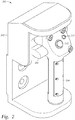
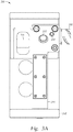
- Figures 2-3C illustrate the tong control assembly 200.
- the tong control assembly 200 may be configured to manually control operation of the tong 100.
- the tong control assembly 200 may be configured to send control signals to the control system 160 for operation of the tong 100.
- the tong control assembly may include a housing 202, a handle 204, a toggle lever 206, electrical connector 208, an indicator light 210, and a push-button control 212.
- the housing 202 may be connected to the frame 110 of the tong 100.
- the housing 202 may be rectangular in shape.
- the housing 202 may have an inner recessed portion.
- the housing 202 may have a lower shoulder and an upper shoulder.
- the inner recessed portion of the housing 202 may be disposed longitudinally between the upper and lower shoulders.
- the handle 204 may be at least partially disposed in the inner recessed portion.
- the handle 204 may be connected to the housing 202, for example by fasteners.
- the handle 204 may be integrally formed with the housing 202.
- the toggle lever 206 may be at least partially disposed in the inner recessed portion of the housing 202.
- the toggle lever 206 may be biased to a neutral position, as shown in Figure 2 .
- the toggle lever 206 may be configured to control the rotational speed of the tong 100, for example the upper jaws 115-U.
- the toggle lever 206 may be pivotally connected to the housing 202.
- the toggle lever 206 may be pivotally movable.
- the toggle lever 206 may be configured to control a rotational direction of the tong 100, for example the upper jaws 115-U.
- the toggle lever 206 may be configured to rotate the upper jaws 115-U in a first direction during make-up of a connection between a tubular and a tubular string.
- the toggle lever 206 may be configured to rotate the jaws 115-U in a second direction during break-out of a tubular and a tubular string.
- the toggle lever 206 may be configured to rotate the upper jaws 115-U bi-directionally.
- the toggle lever 206 may be configured to rotate the jaws 115-U clockwise and counterclockwise.
- the toggle lever 206 may pivot in a vertical plane.
- the toggle lever 206 may be movable to control the rotational speed of the jaws 115-U during at least a portion of make-up and/or break-out of a tubular connection.
- the toggle lever 206 may be movable through a continuous range of positions corresponding to rotational speeds of the jaws 115-U.
- the toggle lever 206 may be configured to control a continuous range of rotational speeds of the jaws 115-U.
- the toggle lever 206 may be pivotally movable from the neutral position to a maximum position corresponding to a maximum rotational speed input into the control system 160.
- the toggle lever 206 may be movable through set positions corresponding to rotational speeds of the jaws 115-U.
- the toggle lever 206 may be configured to rotate a rotor of the upper jaws 115-U.
- the toggle lever 206 may be movable in a first direction during the make-up operation of the tong 100.
- the toggle lever 206 may be movable in a second direction during the break-out operation of the tong 100.
- the toggle lever 206 may be pivotable in an upward direction during make-up operations.
- the toggle lever 206 may be pivotable in a downward direction during break-out operations.
- the toggle lever 206 may be located at any suitable position on the housing 202 whereby the operator may operate the toggle lever 206 while grasping the handle 204.
- the toggle lever 206 may be located at a position on the housing 202 whereby the operator may operate the toggle lever 206 with the same hand used to grasp the handle 204.
- the toggle lever 206 may be located at a position on the housing 202 whereby the operator may operate the toggle lever 206 while a shutoff switch 214 is depressed.
- the toggle lever 206 may be configured to control a rotational speed and a rotational direction of a tubular engaged by the jaws.
- the toggle lever 206 may be located in the inner recessed region of the housing 202 behind the handle 204.
- the toggle lever may include a hook-shaped portion. The operator may place a finger in the hook-shaped portion to operate the toggle lever.
- the toggle lever may be disposed on the handle 204.
- the toggle lever may be a push-button.
- the push-button may be movable through a continuous range of positions corresponding to rotational speeds of the jaws.
- the push-button may be disposed on an inward facing surface of the handle 204.
- the electrical connector 208 may be configured to connect to an electrical cable.
- the electrical connector 208 may be disposed on a wall of the housing 202.
- the electrical connector 208 may face outwardly of the housing 202.
- An opposite end of the electrical cable may be connected to the tong control system 160.
- the electrical cable may transfer signals between the tong control assembly 200 to the tong control system 160.
- the indicator light 210 may be configured to indicate an operational mode of the tong 100.
- the indicator light 210 may be disposed on the handle 204.
- the indicator light 210 may be a light emitting diode.
- the indicator light 210 may alternate between off, blinking, and steady-on to indicate the current mode of the tong 100.
- the push-button control 212 may be disposed on the handle 204.
- the push-button control 212 may be located at any suitable position on the handle 204 whereby the operator may depress the push-button control while grasping the handle 204. In some embodiments, the push-button control 212 may be located at a position on the handle 204 whereby the operator can depress the push-button control with the same hand used to grasp the handle 204. In some embodiments, the push-button control 212 can be used to control the tong 100. In some embodiments, the push-button control 212 can be used to initiate an automatic make-up sequence of the tong 100. The indicator light 210 may be configured to blink to indicate the tong 100 is ready to enter the automatic make-up sequence.
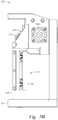
- Figure 3B illustrates a dead man or shutoff switch 214 of the tong control assembly 200.
- the dead man switch 214 may be disposed on the handle 204.
- the dead man switch 214 may be integrally formed with the handle 204.
- the dead man switch 214 may include an actuation plate 216.
- the actuation plate 216 may be a cylindrical shell.
- the actuation plate 216 may be disposed on an inner facing portion of the handle 204.
- the tong control assembly 200 may be configured to work only when the dead man switch 214 is squeezed and held.
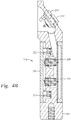
- FIGS 4A and 4B illustrate the handle 204 of the tong control assembly 200.
- the dead man switch 214 may also include push-buttons 218, 220 and one or more biasing members, such as springs 222, 224.
- the actuation plate 216 may include tabs disposed on an inner surface thereof. The tabs of the actuation plate 216 may be configured to engage and depress the corresponding push-buttons 218, 220 when the dead man switch 214 is squeezed and held.
- the springs 222, 224 may be configured to bias the actuation plate 216 outward and the tabs out of engagement with the corresponding push-buttons 218, 220.
- the springs 222, 224 may bias the dead man switch 214 to a neutral position where the push-buttons 218, 220 are not depressed and the tong 100 therefore is prevented from operation.
- the operator may manually enter the size, material, and thread type of the pipe.
- the operator may also enter a set torque, the maximum torque, and/or maximum rotational speed of the pipe.
- the control system 160 may calculate a set torque, final torque, final turns, and/or maximum rotational speed of the pipe based on the size, material, and thread type of the pipe.
- the set torque may correspond to a torque at which the automatic make-up sequence of the tong 100 may be initiated.
- the tong 100 may be operated to add tubulars to a tubular string by the following steps.
- An operator may grasp the tong 100 by the handle 204.
- the handle 204 may be configured to allow the operator to move the tong 100 adjacent a string of tubulars being added to.
- the operator may move the tong 100 adjacent the string of tubulars.
- the dead man switch 214 may be grasped and held in order to allow for operation of the tong 100 and use of the tong control assembly 200.
- the toggle lever 206 may be operated to align a recess in the upper jaws 115-U (the jaws may already be in this configuration following the removal of the tong 100 from a previous section of tubing) with an opening at the front of the upper jaws 115-U.
- the toggle lever 206 may send a signal to the control system 160 to rotate the rotor of the jaws 115-U including the recess.
- the operator may control the speed at which the rotor rotates using the toggle lever 206.
- the recess of the rotor may be aligned with the opening at the front of the jaws 115-U to allow tubulars to be inserted into the tong 100. Two tubulars are then introduced into the openings in the upper and lower jaws through the recesses and the lower tubular is clamped in position in the lower jaws 115-L.
- the toggle lever 206 may be operated to clamp the upper tubular in position in the upper jaws 115-U.
- the toggle lever 206 may send a signal to the control system 160 to rotate the rotor.
- the operator may control the speed at which the rotor rotates using the toggle lever 206.
- the operator may lower the speed at which the rotor rotates by moving the toggle lever 206 closer to the neutral position, shown in Figure 2 .
- the operator may increase the speed at which the rotor rotates by moving the toggle lever 206 further from the neutral position.
- Rotation of the rotor may cause gripping members of the upper jaws 115-U to cam inward and grip the tubular.
- the tong 100 may then be operated to add the tubular to the tubular string.
- the operator may continue to operate the tong 100 using the toggle lever 206.
- the toggle lever 206 may control the rotational speed of the tubular relative to the tubular string.
- the indicator light 210 may be off during manual operation of the tong 100 using the toggle lever 206.
- the control system 160 may send a signal to the tong control assembly 200.
- the indicator light 210 may provide an indication that the automatic make-up sequence can be initiated.
- the indicator light 210 may steadily blink to provide an indication to the operator.
- the control system 160 may require release and reengagement of the dead man switch 214 after reaching the set torque and before beginning the automatic make-up sequence.
- the push-button control 212 may be pressed.
- the push-button control 212 may send a signal from the tong control assembly 200 to the control system 160 to initiate the automatic make-up sequence.
- the control system 160 may control the operation of the tong 100 until the connection is fully tightened.
- the control system 160 may monitor the torque and/or turns of the tubulars to determine if the connection is fully tightened.
- the control system 160 may compare the torque and/or turns to inputs (e.g., final torque, final turns) provided by the operator and/or calculated by the control system 160 based on the thread type, size, and material of the tubulars.
- the indicator light 210 may be steady on during the automatic make-up sequence of the tong 100.
- the toggle lever 206 may be operated to release the clamping force from the tubular.
- the control system 160 may require release and reengagement of the dead man switch 214 after finishing make-up of the connection and before manually operating the tong control assembly 200.
- the toggle lever 206 may be operated to control the tong 100.
- the toggle lever 206 may send a signal to the control system 160 to rotate the rotor of the jaws. Rotation of the rotor may cause the gripping members to retract outward, thereby releasing the clamping force on the tubular.
- the toggle lever 206 may control the rotational speed of the rotor.
- the toggle lever 206 may be operated to rotate the rotor and align the recess of the rotor with the opening of the tong 100. Once aligned, the tong 100 may be removed from the tubular string. The above operation may be repeated to add the desired number of tubulars to the tubular string.
- the tong 100 may be operated to remove tubulars from a tubular string by the following steps.
- An operator may grasp the tong 100 by the handle 204.
- the handle 204 may be configured to allow the operator to move the tong 100 adjacent a string of tubulars being broken up.
- the operator may move the tong 100 adjacent the string of tubulars.
- the dead man switch 214 may be grasped and held in order to allow for operation of the tong 100 and use of the tong control assembly 200.
- the toggle lever 206 may be operated to align the recess in the upper jaws 115-U (the jaws may already be in this configuration following the removal of the tong 100 from a previous section of tubing) with the opening at the front of the upper jaws 115-U.
- the toggle lever 206 may send a signal to the control system 160 to rotate the rotor of the jaws including the recess.
- the operator may control the speed at which the rotor rotates using the toggle lever 206.
- the recess of the rotor may be aligned with the opening at the front of the jaws 115-U to allow the tubular string to be inserted into the tong 100.
- the tubular string is then introduced into the openings in the upper and lower jaws through the recesses and the lower tubular is clamped in position in the lower jaws 115-L.
- the toggle lever 206 may be operated to clamp the upper tubular in position in the upper jaws 115-U.
- the toggle lever 206 may send a signal to the control system 160 to rotate the rotor.
- the operator may control the speed at which the rotor rotates using the toggle lever 206.
- the operator may lower the speed at which the rotor rotates by moving the toggle lever 206 closer to the neutral position, shown in Figure 2 .
- the operator may increase the speed at which the rotor rotates by moving the toggle lever 206 further from the neutral position.
- Rotation of the rotor may cause gripping members of the upper jaws 115-U to cam inward and grip the tubular.
- the tong 100 may then be operated to remove the tubular from the tubular string.
- the operator may continue to operate the tong 100 using the toggle lever 206.
- the toggle lever 206 may control the rotational speed of the tubular relative to the tubular string.
- the toggle lever 206 may be operated until the connection between the upper tubular and the tubular string is broken-out.
- the toggle lever 206 may be operated to release the clamping force from the tubular.
- the control system 160 may require release and reengagement of the dead man switch 214 after finishing break-out of the connection and before manually operating the tong control assembly 200.
- the toggle lever 206 may be operated to control the tong 100.
- the toggle lever 206 may send a signal to the control system 160 to rotate the rotor. Rotation of the rotor may cause the gripping members to retract outward, thereby releasing the clamping force on the tubular.
- the toggle lever 206 may control the rotational speed of the rotor.
- the toggle lever 206 may be operated to rotate the rotor and align the recess of the rotor with the opening of the tong 100. Once aligned, the tong 100 may be removed from the tubular and the tubular string. The above operation may be repeated to remove the desired number of tubulars from the tubular string.
- Conventional tongs may be retrofitted with one or more embodiments of the tong control assembly.
- a tong in one or more of the embodiments described herein, includes a frame having jaws configured to engage a tubular, a tong control assembly disposed on the frame, the tong control assembly including a toggle lever configured to control a rotational speed of the jaws.
- the tong control assembly further includes a housing connected to the frame of the tong.
- toggle lever is movable through a continuous range of rotational speeds.
- the toggle lever is configured to control a continuous range of rotational speeds of the jaws.
- toggle lever is pivotally movable.
- toggle lever is configured to rotate the jaws bi-directionally.
- the toggle lever is configured to control a rotational speed of a tubular engaged by the jaws.
- the tong control assembly further includes a handle connected to the housing, a shutoff switch, an indicator light, and a push-button.
- the shutoff switch, the indicator light, and the push-button disposed on the handle.
- the indicator light configured to indicate an operational mode of the tong.
- the push-button is configured to initiate an automatic make-up sequence of the tong.
- shutoff switch is configured to be depressed to operate the tong control assembly.
- the toggle lever is located at a suitable position on the housing, whereby the toggle lever is configured to be operated while the shutoff switch is depressed.
- a tong includes a frame having first jaws configured to engage a tubular, a tong control assembly disposed on the frame, the tong control assembly including a housing connected to the frame, a handle connected to the housing, a shutoff switch, and a toggle lever configured to control a rotational speed of the first jaws, wherein the toggle lever is located at a suitable position on the housing, whereby the toggle lever is configured to be operated while the shutoff switch is depressed.
- a method of operating a tong includes clamping a first tubular using first jaws of the tong, clamping a second tubular using second jaws of the tong, rotating the first tubular relative to the second tubular, controlling a rotational speed of the first tubular using a toggle lever disposed on a frame of the tong.
- the method further includes while controlling the rotational speed of the first tubular, connecting the first tubular and the second tubular.
- the method further includes while controlling the rotational speed of the first tubular, breaking a connection between the first tubular and the second tubular.
- the method further includes controlling the rotational speed of the first tubular to reach a set torque.
- the method further includes initiating an automatic connection sequence after reaching the set torque
- the method further includes while controlling a rotational speed of the first tubular, depressing a shutoff switch of a tong control assembly disposed on the tong.
- controlling the rotational speed of the first tubular comprises pivotally moving the toggle lever.
- a method includes installing a tong control assembly on a frame of a tong, the tong control assembly including a toggle lever and controlling a rotational speed of the first jaws using the toggle lever.
- a tong in one or more of the embodiments described herein, includes a frame having a first jaws configured to engage a tubular, a tong control assembly disposed on the frame.
- the tong control assembly includes a housing connected to the frame, a shutoff switch, and a toggle lever located at a suitable position on the housing, whereby the toggle lever is configured to be operated while the shutoff switch is depressed, and wherein the toggle lever is configured to control at least one of: a rotational speed of the first jaws and a rotational direction of the first jaws.
- a tong includes a frame having a first jaws configured to engage a tubular, a tong control assembly disposed on the frame including a housing connected to the frame, a handle connected to the housing, and a toggle lever configured to control a rotational speed and a rotational direction of the first jaws.
- the toggle lever is configured to control a rotational speed and a rotational direction of a tubular engaged by the first jaws.
Landscapes
- Engineering & Computer Science (AREA)
- Life Sciences & Earth Sciences (AREA)
- Geology (AREA)
- Mining & Mineral Resources (AREA)
- Mechanical Engineering (AREA)
- Physics & Mathematics (AREA)
- Environmental & Geological Engineering (AREA)
- Fluid Mechanics (AREA)
- General Life Sciences & Earth Sciences (AREA)
- Geochemistry & Mineralogy (AREA)
- Earth Drilling (AREA)
- Manipulator (AREA)
Abstract
Description
- Embodiments of the present invention generally relate to apparatus and methods for operating a tong.
- Construction of oil or gas wells usually requires making long tubular strings that make up casing, risers, drill pipe, or other tubing. Due to the length of these strings, sections or joints of tubulars are progressively added to or removed from the tubular strings as they are lowered or raised from a drilling platform. Tongs are devices used on oil and gas rigs for gripping and/or rotating tubular members, such as casing, drill pipe, drill collars, and coiled tubing (herein referred to collectively as tubulars and/or tubular strings). Tongs may be used to make-up or break-out threaded joints between tubulars. Tongs typically resemble large wrenches, and may sometimes be referred to as power tongs, torque wrenches, spinning wrenches, and/or iron roughnecks. Tongs typically use hydraulic power to provide sufficiently high torque to make-up or break-out threaded joints between tubulars.
- Historically, tongs have been either manually operated or controlled remotely by an operator in the driller's cabin. Onboard tong control has heretofore not been achievable due to control system size, power, and safety requirements.
- Onboard control of a tong may provide improved handling, greater reliability, and increased safety and efficiency.
- Embodiments of the present invention generally relate to apparatus and methods for operating a tong.
- A tong includes a frame having jaws configured to engage a tubular and a tong control assembly disposed on the frame. The tong control assembly includes a toggle lever configured to control a rotational speed of the jaws.
- A tong includes a frame having jaws configured to engage a tubular and a tong control assembly disposed on the frame. The tong control assembly includes a housing connected to the frame, a handle connected to the housing, and a toggle lever configured to control a rotational speed of the jaws. The toggle lever is located at a suitable position on the housing, whereby the toggle lever is configured to be operated while the shutoff switch is depressed.
- A tong includes a frame having jaws configured to engage a tubular, a tong control assembly disposed on the frame. The tong control assembly includes a housing connected to the frame, a shutoff switch, and a toggle lever located at a suitable position on the housing, whereby the toggle lever is configured to be operated while the shutoff switch is depressed, and wherein the toggle lever is configured to control at least one of: a rotational speed of the jaws and a rotational direction of the jaws.
- A tong includes a frame having jaws configured to engage a tubular, a tong control assembly disposed on the frame including a housing connected to the frame, a handle connected to the housing, and a toggle lever configured to control a rotational speed and a rotational direction of the jaws.
- A method for operating a tong includes clamping a first tubular using first jaws of the tong, clamping a second tubular using second jaws of the tong, rotating the first tubular relative to the second tubular, controlling a rotational speed of the first tubular using a toggle lever disposed on a frame of the tong.
- A method includes installing a tong control assembly on a frame having jaws configured to engage a tubular, the tong control assembly including a toggle lever and controlling a rotational speed of the jaws using the toggle lever.
- So that the manner in which the above recited features of the present disclosure can be understood in detail, a more particular description of the disclosure, briefly summarized above, may be had by reference to embodiments, some of which are illustrated in the appended drawings. It is to be noted, however, that the appended drawings illustrate only typical embodiments of this disclosure and are therefore not to be considered limiting of its scope, for the disclosure may admit to other equally effective embodiments.
-
Figure 1 illustrates an exemplary tong according to embodiments described herein. -
Figure 2 illustrates an isometric view of an exemplary tong control assembly for the tong ofFigure 1 . -
Figure 3A illustrates a front view of the exemplary tong control assembly ofFigure 2 . -
Figure 3B illustrates a side view of the exemplary tong control assembly ofFigure 2 . -
Figure 3C illustrates an opposite side view of the exemplary tong control assembly ofFigure 2 . -
Figure 4A illustrates an isometric view of a handle of the exemplary tong control assembly. -
Figure 4B illustrates a cross-sectional view of the handle ofFigure 4A . - Embodiments of the present invention generally relate to apparatus and methods for operating a tong.
- In some embodiments, a tong control system may be small (e.g., less than about 0.61 m (2 feet) in any dimension; for example 40 cm (16") by 40cm (16") by 15cm (6")), so that it can be placed on the tong. Consequently, existing tongs may be beneficially retrofitted.
- A tong control system may monitor and actuate several parts of the tong. For example, the tong control system may monitor and actuate components of the tong to provide varying torque and/or angular displacement. Disconnection of a tubular joint may require both a high-torque/low-angular displacement "break" action to disengage the contact shoulders, and a low-torque/high-angular displacement "spin" action to screw-out the threads. Connection of a tubular joint may occur in the reverse sequence. In the make/break action, torque may be high (e.g., 13,558-135,581 N-m (10,000-100,000 ft-lbf)), having a small (e.g., 0.12-0.24 revolutions) angular displacement. In the spin action, torque may be low (e.g., 1,355-4,067 N-m (1,000-3,000 ft-lbf)), having a large (e.g., 3-5 revolutions) angular displacement.
- As another example, the tong control system may monitor and actuate components of the tong to provide varying clamping and rotation actions. Upper and lower jaws of the tong may turn relative to each other to break a connection between upper and lower tool joints. The upper jaw may then be released while the lower jaw remains clamped onto the lower tool joint. A spinning wrench, commonly separate from the torque wrench and mounted higher up on the carriage, may engage the stem of the upper joint of drill pipe to spin the upper joint until it is disconnected from the lower joint. Upper and lower jaws of the tong may turn relative to each other to make-up two joints of pipe. The lower jaw may grip the lower tool joint while the upper pipe is brought into position. The spinning wrench may engage the upper joint to spin it into the lower joint. The torque wrench may clamp the pipe and tighten the connection.
-
Figure 1 illustrates anexemplary tong 100. Thetong 100 may include aframe 110. Theframe 110 may include a plurality ofjaws 115, for example a first or upper jaws 115-U and a second or lower jaws 115-L. The jaws may be configured to grip and/or rotate tubulars. The jaws (or portions thereof) may move (e.g., rotate) relative to theframe 110. Consequently, thejaws 115 may be referred to as a rotating portion of thetong 100, and theframe 110 may be referred to as a stationary portion of thetong 100. In some embodiments, thetong 100 may include acontrol system 160 for tong control. Thetong 100 may also include electrical equipment (e.g., actuators, sensors). Thetong 100 may include atong control assembly 200. In some embodiments, thecontrol system 160 and thetong control assembly 200 may be disposed on a stationary portion of thetong 100, for example theframe 110. Thetong 100 may also include manual levers for manually controlling operation of thetong 100 and the plurality of jaws. The levers may be disposed on a stationary portion of thetong 100, for example theframe 110. Thetong control assembly 200 may be configured to operate other tong embodiments. An exemplary tong is disclosed inU.S. Patent Application Publication No. 2004/0237726 . - In some embodiments,
tong control system 160 may be configured to control how thetong 100 handles tubulars, grips tubulars, turns tubulars, and/or manages hydraulic power for handling, gripping, and/or turning tubulars. In some embodiments,tong control system 160 may be configured to receive input (e.g., from sensors) regarding how thetong 100 interacts with tubulars. In some embodiments,tong control system 160 may be configured to process and/or store data (e.g., pipe size, thread size, thread count, etc.) regarding how thetong 100 interacts with tubulars. In some embodiments,tong control system 160 may be configured to generate and/or send control signals to control how thetong 100 interacts with tubulars.Tong control system 160 may include a torque sensor (e.g., a load cell) and/or a turns counter. In some embodiments,tong control system 160 may be configured to also receive input from a clock.Tong control system 160 may include data storage and/or data processors.Tong control system 160 may include a tubular gripping actuator, a tubular turning actuator, and/or a hydraulic power control actuator (e.g., a dump valve). In some embodiments,tong control system 160 may be configured to send control signals to a tubular gripping actuator, a tubular turning actuator, and/or a hydraulic power control actuator. In some embodiments,tong control system 160 may be configured to also send control signals to a jaw positioning actuator. -
Figures 2-3C illustrate thetong control assembly 200. In some embodiments, thetong control assembly 200 may be configured to manually control operation of thetong 100. In some embodiments, thetong control assembly 200 may be configured to send control signals to thecontrol system 160 for operation of thetong 100. In one embodiment, the tong control assembly may include ahousing 202, ahandle 204, atoggle lever 206,electrical connector 208, anindicator light 210, and a push-button control 212. Thehousing 202 may be connected to theframe 110 of thetong 100. Thehousing 202 may be rectangular in shape. Thehousing 202 may have an inner recessed portion. Thehousing 202 may have a lower shoulder and an upper shoulder. The inner recessed portion of thehousing 202 may be disposed longitudinally between the upper and lower shoulders. Thehandle 204 may be at least partially disposed in the inner recessed portion. Thehandle 204 may be connected to thehousing 202, for example by fasteners. Alternatively, thehandle 204 may be integrally formed with thehousing 202. - The
toggle lever 206 may be at least partially disposed in the inner recessed portion of thehousing 202. Thetoggle lever 206 may be biased to a neutral position, as shown inFigure 2 . Thetoggle lever 206 may be configured to control the rotational speed of thetong 100, for example the upper jaws 115-U. Thetoggle lever 206 may be pivotally connected to thehousing 202. Thetoggle lever 206 may be pivotally movable. Thetoggle lever 206 may be configured to control a rotational direction of thetong 100, for example the upper jaws 115-U. For example, thetoggle lever 206 may be configured to rotate the upper jaws 115-U in a first direction during make-up of a connection between a tubular and a tubular string. Thetoggle lever 206 may be configured to rotate the jaws 115-U in a second direction during break-out of a tubular and a tubular string. Thetoggle lever 206 may be configured to rotate the upper jaws 115-U bi-directionally. For example, thetoggle lever 206 may be configured to rotate the jaws 115-U clockwise and counterclockwise. Thetoggle lever 206 may pivot in a vertical plane. Thetoggle lever 206 may be movable to control the rotational speed of the jaws 115-U during at least a portion of make-up and/or break-out of a tubular connection. In some embodiments, thetoggle lever 206 may be movable through a continuous range of positions corresponding to rotational speeds of the jaws 115-U. Thetoggle lever 206 may be configured to control a continuous range of rotational speeds of the jaws 115-U. For example, thetoggle lever 206 may be pivotally movable from the neutral position to a maximum position corresponding to a maximum rotational speed input into thecontrol system 160. In some embodiments, thetoggle lever 206 may be movable through set positions corresponding to rotational speeds of the jaws 115-U. Thetoggle lever 206 may be configured to rotate a rotor of the upper jaws 115-U. Thetoggle lever 206 may be movable in a first direction during the make-up operation of thetong 100. Thetoggle lever 206 may be movable in a second direction during the break-out operation of thetong 100. For example, thetoggle lever 206 may be pivotable in an upward direction during make-up operations. Thetoggle lever 206 may be pivotable in a downward direction during break-out operations. In some embodiments, thetoggle lever 206 may be located at any suitable position on thehousing 202 whereby the operator may operate thetoggle lever 206 while grasping thehandle 204. In some embodiments, thetoggle lever 206 may be located at a position on thehousing 202 whereby the operator may operate thetoggle lever 206 with the same hand used to grasp thehandle 204. In some embodiments, thetoggle lever 206 may be located at a position on thehousing 202 whereby the operator may operate thetoggle lever 206 while ashutoff switch 214 is depressed. Thetoggle lever 206 may be configured to control a rotational speed and a rotational direction of a tubular engaged by the jaws. In some embodiments, thetoggle lever 206 may be located in the inner recessed region of thehousing 202 behind thehandle 204. In some embodiments, the toggle lever may include a hook-shaped portion. The operator may place a finger in the hook-shaped portion to operate the toggle lever. In some embodiments, the toggle lever may be disposed on thehandle 204. The toggle lever may be a push-button. The push-button may be movable through a continuous range of positions corresponding to rotational speeds of the jaws. The push-button may be disposed on an inward facing surface of thehandle 204. - The
electrical connector 208 may be configured to connect to an electrical cable. Theelectrical connector 208 may be disposed on a wall of thehousing 202. Theelectrical connector 208 may face outwardly of thehousing 202. An opposite end of the electrical cable may be connected to thetong control system 160. The electrical cable may transfer signals between thetong control assembly 200 to thetong control system 160. Theindicator light 210 may be configured to indicate an operational mode of thetong 100. Theindicator light 210 may be disposed on thehandle 204. Theindicator light 210 may be a light emitting diode. Theindicator light 210 may alternate between off, blinking, and steady-on to indicate the current mode of thetong 100. The push-button control 212 may be disposed on thehandle 204. The push-button control 212 may be located at any suitable position on thehandle 204 whereby the operator may depress the push-button control while grasping thehandle 204. In some embodiments, the push-button control 212 may be located at a position on thehandle 204 whereby the operator can depress the push-button control with the same hand used to grasp thehandle 204. In some embodiments, the push-button control 212 can be used to control thetong 100. In some embodiments, the push-button control 212 can be used to initiate an automatic make-up sequence of the tong 100.Theindicator light 210 may be configured to blink to indicate thetong 100 is ready to enter the automatic make-up sequence. -
Figure 3B illustrates a dead man orshutoff switch 214 of thetong control assembly 200. Thedead man switch 214 may be disposed on thehandle 204. Thedead man switch 214 may be integrally formed with thehandle 204. Thedead man switch 214 may include anactuation plate 216. Theactuation plate 216 may be a cylindrical shell. Theactuation plate 216 may be disposed on an inner facing portion of thehandle 204. In some embodiments, thetong control assembly 200 may be configured to work only when thedead man switch 214 is squeezed and held. -
Figures 4A and4B illustrate thehandle 204 of thetong control assembly 200. Thedead man switch 214 may also include push-buttons springs actuation plate 216 may include tabs disposed on an inner surface thereof. The tabs of theactuation plate 216 may be configured to engage and depress the corresponding push-buttons dead man switch 214 is squeezed and held. Thesprings actuation plate 216 outward and the tabs out of engagement with the corresponding push-buttons springs dead man switch 214 to a neutral position where the push-buttons tong 100 therefore is prevented from operation. - Before makeup begins, the operator may manually enter the size, material, and thread type of the pipe. The operator may also enter a set torque, the maximum torque, and/or maximum rotational speed of the pipe. In the alternative, the
control system 160 may calculate a set torque, final torque, final turns, and/or maximum rotational speed of the pipe based on the size, material, and thread type of the pipe. The set torque may correspond to a torque at which the automatic make-up sequence of thetong 100 may be initiated. - In some embodiments, the
tong 100 may be operated to add tubulars to a tubular string by the following steps. An operator may grasp thetong 100 by thehandle 204. Thehandle 204 may be configured to allow the operator to move thetong 100 adjacent a string of tubulars being added to. The operator may move thetong 100 adjacent the string of tubulars. Thedead man switch 214 may be grasped and held in order to allow for operation of thetong 100 and use of thetong control assembly 200. Thetoggle lever 206 may be operated to align a recess in the upper jaws 115-U (the jaws may already be in this configuration following the removal of thetong 100 from a previous section of tubing) with an opening at the front of the upper jaws 115-U. Thetoggle lever 206 may send a signal to thecontrol system 160 to rotate the rotor of the jaws 115-U including the recess. The operator may control the speed at which the rotor rotates using thetoggle lever 206. The recess of the rotor may be aligned with the opening at the front of the jaws 115-U to allow tubulars to be inserted into thetong 100. Two tubulars are then introduced into the openings in the upper and lower jaws through the recesses and the lower tubular is clamped in position in the lower jaws 115-L. - Next, the
toggle lever 206 may be operated to clamp the upper tubular in position in the upper jaws 115-U. Thetoggle lever 206 may send a signal to thecontrol system 160 to rotate the rotor. The operator may control the speed at which the rotor rotates using thetoggle lever 206. The operator may lower the speed at which the rotor rotates by moving thetoggle lever 206 closer to the neutral position, shown inFigure 2 . The operator may increase the speed at which the rotor rotates by moving thetoggle lever 206 further from the neutral position. Rotation of the rotor may cause gripping members of the upper jaws 115-U to cam inward and grip the tubular. Thetong 100 may then be operated to add the tubular to the tubular string. The operator may continue to operate thetong 100 using thetoggle lever 206. Thetoggle lever 206 may control the rotational speed of the tubular relative to the tubular string. Theindicator light 210 may be off during manual operation of thetong 100 using thetoggle lever 206. As the connection is made-up, the torque applied by thetong 100 and measured by thecontrol system 160 may increase. Once the connection reaches the set torque, thecontrol system 160 may send a signal to thetong control assembly 200. Theindicator light 210 may provide an indication that the automatic make-up sequence can be initiated. For example, theindicator light 210 may steadily blink to provide an indication to the operator. Optionally, thecontrol system 160 may require release and reengagement of thedead man switch 214 after reaching the set torque and before beginning the automatic make-up sequence. - In the next step of the operation, the push-
button control 212 may be pressed. The push-button control 212 may send a signal from thetong control assembly 200 to thecontrol system 160 to initiate the automatic make-up sequence. Thecontrol system 160 may control the operation of thetong 100 until the connection is fully tightened. Thecontrol system 160 may monitor the torque and/or turns of the tubulars to determine if the connection is fully tightened. Thecontrol system 160 may compare the torque and/or turns to inputs (e.g., final torque, final turns) provided by the operator and/or calculated by thecontrol system 160 based on the thread type, size, and material of the tubulars. Theindicator light 210 may be steady on during the automatic make-up sequence of thetong 100. - After finishing make-up of the connection between the tubular and the tubular string, the
toggle lever 206 may be operated to release the clamping force from the tubular. Optionally, thecontrol system 160 may require release and reengagement of thedead man switch 214 after finishing make-up of the connection and before manually operating thetong control assembly 200. Thetoggle lever 206 may be operated to control thetong 100. Thetoggle lever 206 may send a signal to thecontrol system 160 to rotate the rotor of the jaws. Rotation of the rotor may cause the gripping members to retract outward, thereby releasing the clamping force on the tubular. Thetoggle lever 206 may control the rotational speed of the rotor. After releasing the clamping force on the tubular, thetoggle lever 206 may be operated to rotate the rotor and align the recess of the rotor with the opening of thetong 100. Once aligned, thetong 100 may be removed from the tubular string. The above operation may be repeated to add the desired number of tubulars to the tubular string. - In some embodiments, the
tong 100 may be operated to remove tubulars from a tubular string by the following steps. An operator may grasp thetong 100 by thehandle 204. Thehandle 204 may be configured to allow the operator to move thetong 100 adjacent a string of tubulars being broken up. The operator may move thetong 100 adjacent the string of tubulars. Thedead man switch 214 may be grasped and held in order to allow for operation of thetong 100 and use of thetong control assembly 200. Thetoggle lever 206 may be operated to align the recess in the upper jaws 115-U (the jaws may already be in this configuration following the removal of thetong 100 from a previous section of tubing) with the opening at the front of the upper jaws 115-U. Thetoggle lever 206 may send a signal to thecontrol system 160 to rotate the rotor of the jaws including the recess. The operator may control the speed at which the rotor rotates using thetoggle lever 206. The recess of the rotor may be aligned with the opening at the front of the jaws 115-U to allow the tubular string to be inserted into thetong 100. The tubular string is then introduced into the openings in the upper and lower jaws through the recesses and the lower tubular is clamped in position in the lower jaws 115-L. - Next, the
toggle lever 206 may be operated to clamp the upper tubular in position in the upper jaws 115-U. Thetoggle lever 206 may send a signal to thecontrol system 160 to rotate the rotor. The operator may control the speed at which the rotor rotates using thetoggle lever 206. The operator may lower the speed at which the rotor rotates by moving thetoggle lever 206 closer to the neutral position, shown inFigure 2 . The operator may increase the speed at which the rotor rotates by moving thetoggle lever 206 further from the neutral position. Rotation of the rotor may cause gripping members of the upper jaws 115-U to cam inward and grip the tubular. Thetong 100 may then be operated to remove the tubular from the tubular string. The operator may continue to operate thetong 100 using thetoggle lever 206. Thetoggle lever 206 may control the rotational speed of the tubular relative to the tubular string. Thetoggle lever 206 may be operated until the connection between the upper tubular and the tubular string is broken-out. - After finishing break-out of the connection between the tubular and the tubular string, the
toggle lever 206 may be operated to release the clamping force from the tubular. Optionally, thecontrol system 160 may require release and reengagement of thedead man switch 214 after finishing break-out of the connection and before manually operating thetong control assembly 200. Thetoggle lever 206 may be operated to control thetong 100. Thetoggle lever 206 may send a signal to thecontrol system 160 to rotate the rotor. Rotation of the rotor may cause the gripping members to retract outward, thereby releasing the clamping force on the tubular. Thetoggle lever 206 may control the rotational speed of the rotor. After releasing the clamping force on the tubular, thetoggle lever 206 may be operated to rotate the rotor and align the recess of the rotor with the opening of thetong 100. Once aligned, thetong 100 may be removed from the tubular and the tubular string. The above operation may be repeated to remove the desired number of tubulars from the tubular string. - Conventional tongs may be retrofitted with one or more embodiments of the tong control assembly.
- In one or more of the embodiments described herein, a tong includes a frame having jaws configured to engage a tubular, a tong control assembly disposed on the frame, the tong control assembly including a toggle lever configured to control a rotational speed of the jaws.
- In one or more of the embodiments described herein, the tong control assembly further includes a housing connected to the frame of the tong.
- In one or more of the embodiments described herein, wherein the toggle lever is movable through a continuous range of rotational speeds.
- In one or more of the embodiments described herein, the toggle lever is configured to control a continuous range of rotational speeds of the jaws.
- In one or more of the embodiments described herein, wherein the toggle lever is pivotally movable.
- In one or more of the embodiments described herein, wherein the toggle lever is configured to rotate the jaws bi-directionally.
- In one or more of the embodiments described herein, wherein the toggle lever is configured to control a rotational speed of a tubular engaged by the jaws.
- In one or more of the embodiments described herein, the tong control assembly further includes a handle connected to the housing, a shutoff switch, an indicator light, and a push-button.
- In one or more of the embodiments described herein, the shutoff switch, the indicator light, and the push-button disposed on the handle.
- In one or more of the embodiments described herein, the indicator light configured to indicate an operational mode of the tong.
- In one or more of the embodiments described herein, wherein the push-button is configured to initiate an automatic make-up sequence of the tong.
- In one or more of the embodiments described herein, wherein the shutoff switch is configured to be depressed to operate the tong control assembly.
- In one or more of the embodiments described herein, wherein the toggle lever is located at a suitable position on the housing, whereby the toggle lever is configured to be operated while the shutoff switch is depressed.
- In one or more of the embodiments described herein, a tong includes a frame having first jaws configured to engage a tubular, a tong control assembly disposed on the frame, the tong control assembly including a housing connected to the frame, a handle connected to the housing, a shutoff switch, and a toggle lever configured to control a rotational speed of the first jaws, wherein the toggle lever is located at a suitable position on the housing, whereby the toggle lever is configured to be operated while the shutoff switch is depressed.
- In one or more of the embodiments described herein, a method of operating a tong includes clamping a first tubular using first jaws of the tong, clamping a second tubular using second jaws of the tong, rotating the first tubular relative to the second tubular, controlling a rotational speed of the first tubular using a toggle lever disposed on a frame of the tong.
- In one or more of the embodiments described herein, the method further includes while controlling the rotational speed of the first tubular, connecting the first tubular and the second tubular.
- In one or more of the embodiments described herein, the method further includes while controlling the rotational speed of the first tubular, breaking a connection between the first tubular and the second tubular.
- In one or more of the embodiments described herein, the method further includes controlling the rotational speed of the first tubular to reach a set torque.
- In one or more of the embodiments described herein, the method further includes initiating an automatic connection sequence after reaching the set torque
- In one or more of the embodiments described herein, the method further includes while controlling a rotational speed of the first tubular, depressing a shutoff switch of a tong control assembly disposed on the tong.
- In one or more of the embodiments described herein, wherein controlling the rotational speed of the first tubular comprises pivotally moving the toggle lever.
- In one or more of the embodiments described herein, a method includes installing a tong control assembly on a frame of a tong, the tong control assembly including a toggle lever and controlling a rotational speed of the first jaws using the toggle lever.
- In one or more of the embodiments described herein, a tong includes a frame having a first jaws configured to engage a tubular, a tong control assembly disposed on the frame. The tong control assembly includes a housing connected to the frame, a shutoff switch, and a toggle lever located at a suitable position on the housing, whereby the toggle lever is configured to be operated while the shutoff switch is depressed, and wherein the toggle lever is configured to control at least one of: a rotational speed of the first jaws and a rotational direction of the first jaws.
- In one or more of the embodiments described herein, a tong includes a frame having a first jaws configured to engage a tubular, a tong control assembly disposed on the frame including a housing connected to the frame, a handle connected to the housing, and a toggle lever configured to control a rotational speed and a rotational direction of the first jaws.
- In one or more of the embodiments described herein, the toggle lever is configured to control a rotational speed and a rotational direction of a tubular engaged by the first jaws.
- While the foregoing is directed to embodiments of the present invention, other and further embodiments of the invention may be devised without departing from the basic scope thereof, and the scope thereof is determined by the claims that follow.
- Embodiments of the invention may include one or more of the following numbered clauses:
- 1. A tong for engaging a tubular, comprising:
- a frame having jaws configured to engage the tubular;
- a tong control assembly disposed on the frame, including:
- a housing connected to the frame;
- a shutoff switch; and
- a toggle lever located at a suitable position on the housing, whereby the toggle lever is configured to be operated while the shutoff switch is depressed, and wherein the toggle lever is configured to control at least one of:
- a rotational speed of the jaws; and
- a rotational direction of the jaws.
- 2. The tong of clause 1, wherein the toggle lever is configured to control a continuous range of rotational speeds of the jaws.
- 3. The tong of clause 1, wherein the toggle lever is pivotally movable.
- 4. The tong of clause 1, wherein the toggle lever is configured to control a rotational speed and a rotational direction of a tubular engaged by the jaws.
- 5. The tong of clause 1, the tong control assembly further including:
- a handle connected to the housing;
- an indicator light; and
- a push-button.
- 6. The tong of clause 5, wherein the indicator light is configured to indicate an operational mode of the tong.
- 7. The tong of clause 5, wherein the push-button is configured to initiate an automatic make-up sequence of the tong.
- 8. The tong of clause 5, wherein the shutoff switch, indicator light, and push-button are disposed on the handle.
- 9. A tong for engaging a tubular, comprising:
- a frame having jaws configured to engage the tubular;
- a tong control assembly disposed on the frame, comprising:
- a housing connected to the frame;
- a handle connected to the housing; and
- a toggle lever configured to control a rotational speed and a rotational direction of the jaws.
- 10. The tong of clause 9, wherein the toggle lever is pivotally movable.
- 11. The tong of clause 9, the tong control assembly further comprising:
- an indicator light configured to indicate an operational mode of the tong;
- a push-button configured to initiate an automatic make-up sequence of the tong; and
- a shutoff switch disposed on the handle.
- 12. The tong of clause 9, wherein the toggle lever is configured to control a rotational speed and a rotational direction of a tubular engaged by the jaws.
- 13. The tong of clause 9, wherein the toggle lever is configured to control a continuous range of rotational speeds of the jaws.
- 14. A method of operating a tong, comprising:
- clamping a first tubular using first jaws of the tong;
- clamping a second tubular using second jaws of the tong;
- rotating the first tubular relative to the second tubular; and
- controlling a rotational speed of the first tubular using a toggle lever disposed on a frame of the tong.
- 15. The method of clause 14, further comprising while controlling the rotational speed of the first tubular, connecting the first tubular and the second tubular.
- 16. The method of clause 14, further comprising while controlling the rotational speed of the first tubular, breaking a connection between the first tubular and the second tubular.
- 17. The method of clause 14, further comprising controlling the rotational speed of the first tubular to reach a set torque.
- 18. The method of clause 17, further comprising initiating an automatic connection sequence after reaching the set torque.
- 19. The method of clause 14, further comprising while controlling a rotational speed of the first tubular, depressing a shutoff switch of a tong control assembly disposed on the tong.
- 20. The method of clause 14, wherein controlling the rotational speed of the first tubular comprises pivotally moving the toggle lever.
Claims (15)
- A control assembly (200) for controlling a tubular handling apparatus (100), comprising:a housing (202);a handle (204) connected to the housing (202); anda toggle lever (206) configured to control the tubular handling apparatus (100);wherein the handle (204) and the toggle lever (206) are positioned such that a single hand can grasp the handle (204) and operate the toggle lever (206).
- The control assembly (200) of claim 1, wherein the toggle lever (206) is pivotally connected to the housing (204).
- The control assembly (200) of claim 1, further comprising a shutoff switch (214), wherein the shutoff switch (214) is positioned such that the single hand can operate the shutoff switch (214) and the toggle lever (206) together.
- The control assembly (200) of claim 3, wherein the shutoff switch (214) includes:an actuation plate (216) configured to be engaged by the single hand and moved from a neutral position to a depressed position;one or more biasing members (222, 224) disposed in the handle (204) configured to bias the actuation plate (216) towards the neutral position; andone or more push-buttons (218, 220) disposed in the handle (204), wherein the actuation plate (216) is configured to depress the one or more push-buttons (218, 220) in the depressed position.
- The control assembly (200) of claim 1, wherein the toggle lever (206) is disposed on the handle (204).
- The control assembly (200) of claim 1, further comprising a push-button control (212).
- The control assembly (200) of claim 6, wherein the push-button control (212) is positioned such that the single hand can depress the push-button control (212).
- The control assembly (200) of claim 1, further comprising an electrical connector (208) configured to transfer one or more signals between the control assembly (200) and the tubular handling apparatus (100).
- The control assembly (200) of claim 1, wherein the toggle lever (206) is pivotable in a first direction to control a first range of rotational speeds of the tubular handling apparatus (100) in a first rotational direction of the tubular handling apparatus (100).
- The control assembly (200) of claim 9, wherein the toggle lever (206) is pivotable in a second direction to control a second range of rotational speeds of the tubular handling apparatus (100) in a second rotational direction of the tubular handling apparatus.
- The control assembly (200) of claim 1, wherein the housing (202) includes a recessed portion and the toggle lever (206) is at least partially disposed in the recessed portion.
- A method of operating a tubular handling apparatus (100), comprising:grasping, with a single hand, a handle (204) of a control assembly (200), the control assembly (200) further including a toggle lever (206) configured to control the tubular handling apparatus (100);operating, with the single hand, the toggle lever (206) of the control assembly (200) to control the tubular handling apparatus (100), wherein the toggle lever (206) is positioned such that the single hand can operate the toggle lever (206) and grasp the handle (204) of the control assembly (200).
- The method of claim 12, further comprising:
prior to and during the operating of the toggle lever (206), operating a shutoff switch (214) of the control assembly (200) with the single hand. - The method of claim 12, further comprising:
operating a push-button controller (212) of the control assembly (200) with the single hand. - The method of claim 12, further comprising:
prior to the grasping of the handle (204) and prior to the operating of the toggle lever (206), electrically connecting the control assembly (200) to the tubular handling apparatus (100).
Applications Claiming Priority (3)
| Application Number | Priority Date | Filing Date | Title |
|---|---|---|---|
| US15/682,427 US10472906B2 (en) | 2017-08-21 | 2017-08-21 | Apparatus and methods for tong operation |
| EP18762973.8A EP3673141B1 (en) | 2017-08-21 | 2018-08-14 | Apparatus and methods for tong operation |
| PCT/US2018/046736 WO2019040325A1 (en) | 2017-08-21 | 2018-08-14 | APPARATUS AND METHODS FOR CLAMP OPERATION |
Related Parent Applications (2)
| Application Number | Title | Priority Date | Filing Date |
|---|---|---|---|
| EP18762973.8A Division EP3673141B1 (en) | 2017-08-21 | 2018-08-14 | Apparatus and methods for tong operation |
| EP18762973.8A Division-Into EP3673141B1 (en) | 2017-08-21 | 2018-08-14 | Apparatus and methods for tong operation |
Publications (2)
| Publication Number | Publication Date |
|---|---|
| EP3730734A1 true EP3730734A1 (en) | 2020-10-28 |
| EP3730734B1 EP3730734B1 (en) | 2024-05-15 |
Family
ID=63452730
Family Applications (2)
| Application Number | Title | Priority Date | Filing Date |
|---|---|---|---|
| EP20179556.4A Active EP3730734B1 (en) | 2017-08-21 | 2018-08-14 | Apparatus and methods for tong operation |
| EP18762973.8A Active EP3673141B1 (en) | 2017-08-21 | 2018-08-14 | Apparatus and methods for tong operation |
Family Applications After (1)
| Application Number | Title | Priority Date | Filing Date |
|---|---|---|---|
| EP18762973.8A Active EP3673141B1 (en) | 2017-08-21 | 2018-08-14 | Apparatus and methods for tong operation |
Country Status (5)
| Country | Link |
|---|---|
| US (2) | US10472906B2 (en) |
| EP (2) | EP3730734B1 (en) |
| AU (2) | AU2018321276B2 (en) |
| CA (1) | CA3071715C (en) |
| WO (1) | WO2019040325A1 (en) |
Families Citing this family (3)
| Publication number | Priority date | Publication date | Assignee | Title |
|---|---|---|---|---|
| US11078733B2 (en) * | 2018-08-22 | 2021-08-03 | Weatherford Technology Holdings, Llc | Apparatus and methods for determining operational mode of tong assembly |
| US12134942B2 (en) | 2023-03-10 | 2024-11-05 | Baker Hughes Oilfield Operations Llc | Control of tubular connections based on estimation of turns remaining |
| US12320213B2 (en) * | 2023-07-13 | 2025-06-03 | Weatherford Technology Holdings, LLC. | Electronic limit barrier for hydraulic power tongs |
Citations (3)
| Publication number | Priority date | Publication date | Assignee | Title |
|---|---|---|---|---|
| US5049020A (en) * | 1984-01-26 | 1991-09-17 | John Harrel | Device for positioning and stabbing casing from a remote selectively variable location |
| US20040237726A1 (en) | 2002-02-12 | 2004-12-02 | Schulze Beckinghausen Joerg E. | Tong |
| US20130255446A1 (en) * | 2012-04-03 | 2013-10-03 | Rangeland Industrial Service Ltd. | Power tong apparatus |
Family Cites Families (7)
| Publication number | Priority date | Publication date | Assignee | Title |
|---|---|---|---|---|
| US4593584A (en) | 1984-06-25 | 1986-06-10 | Eckel Manufacturing Co., Inc. | Power tongs with improved hydraulic drive |
| US5988299A (en) | 1995-07-26 | 1999-11-23 | Hansen; James | Automated oil rig servicing system |
| US6119557A (en) | 1998-08-24 | 2000-09-19 | Bilco Tools, Inc. | Power tong with shutdown system and method |
| US6722231B2 (en) * | 2001-03-19 | 2004-04-20 | Hawk Industries, Inc. | Pipe make/break apparatus with gripping jaws and adjustable pipe spinner with oiling system |
| US7559360B2 (en) | 2004-03-24 | 2009-07-14 | John Paul Hobgood | Tong positioning and alignment device |
| US9453377B2 (en) * | 2013-10-21 | 2016-09-27 | Frank's International, Llc | Electric tong system and methods of use |
| US10465494B2 (en) * | 2014-09-15 | 2019-11-05 | Weatherford Technology Holdings, Llc | Universal remote control system for hydrocarbon recovery tools |
-
2017
- 2017-08-21 US US15/682,427 patent/US10472906B2/en active Active
-
2018
- 2018-08-14 AU AU2018321276A patent/AU2018321276B2/en active Active
- 2018-08-14 WO PCT/US2018/046736 patent/WO2019040325A1/en not_active Ceased
- 2018-08-14 CA CA3071715A patent/CA3071715C/en active Active
- 2018-08-14 EP EP20179556.4A patent/EP3730734B1/en active Active
- 2018-08-14 EP EP18762973.8A patent/EP3673141B1/en active Active
-
2019
- 2019-11-08 US US16/678,519 patent/US10822893B2/en active Active
-
2024
- 2024-11-01 AU AU2024259691A patent/AU2024259691B2/en active Active
Patent Citations (3)
| Publication number | Priority date | Publication date | Assignee | Title |
|---|---|---|---|---|
| US5049020A (en) * | 1984-01-26 | 1991-09-17 | John Harrel | Device for positioning and stabbing casing from a remote selectively variable location |
| US20040237726A1 (en) | 2002-02-12 | 2004-12-02 | Schulze Beckinghausen Joerg E. | Tong |
| US20130255446A1 (en) * | 2012-04-03 | 2013-10-03 | Rangeland Industrial Service Ltd. | Power tong apparatus |
Also Published As
| Publication number | Publication date |
|---|---|
| US10822893B2 (en) | 2020-11-03 |
| US20190055796A1 (en) | 2019-02-21 |
| AU2018321276A1 (en) | 2020-03-12 |
| CA3071715A1 (en) | 2019-02-28 |
| AU2024259691A1 (en) | 2024-11-21 |
| CA3071715C (en) | 2022-03-15 |
| AU2024259691B2 (en) | 2025-12-18 |
| EP3730734B1 (en) | 2024-05-15 |
| EP3673141A1 (en) | 2020-07-01 |
| US20200072002A1 (en) | 2020-03-05 |
| WO2019040325A1 (en) | 2019-02-28 |
| US10472906B2 (en) | 2019-11-12 |
| AU2018321276B2 (en) | 2024-09-12 |
| EP3673141B1 (en) | 2022-03-23 |
Similar Documents
| Publication | Publication Date | Title |
|---|---|---|
| AU2024259691A1 (en) | Apparatus And Methods For Tong Operation | |
| US8356675B2 (en) | Apparatus and methods for tubular makeup interlock | |
| US20190136669A1 (en) | Control system for hydrocarbon recovery tools | |
| US8844616B2 (en) | Method for withdrawal and insertion of a drill pipe string in a borehole and also a device for use when practicing the method | |
| US10006260B2 (en) | Power tong spool valve speed limiting system | |
| EP3630414B1 (en) | Wrench assembly with floating torque bodies | |
| SE539108C2 (en) | Drilling arrangements, vehicles, computer programs and the procedure for holding drill stringers | |
| AU2019325256A1 (en) | Apparatus and methods for determining operational mode of tong assembly | |
| US9181766B2 (en) | Breakout tool | |
| US20180058161A1 (en) | Load limiting tong | |
| EP3631146B1 (en) | Wrench assembly with tubular centering device | |
| US20140174261A1 (en) | Power tong and backup tong apparatus | |
| US10094179B2 (en) | Replacable dies | |
| NO20141062A1 (en) | TOOLS FOR REMOVING A TORQUE PIECE |
Legal Events
| Date | Code | Title | Description |
|---|---|---|---|
| PUAI | Public reference made under article 153(3) epc to a published international application that has entered the european phase |
Free format text: ORIGINAL CODE: 0009012 |
|
| STAA | Information on the status of an ep patent application or granted ep patent |
Free format text: STATUS: REQUEST FOR EXAMINATION WAS MADE |
|
| 17P | Request for examination filed |
Effective date: 20200611 |
|
| AC | Divisional application: reference to earlier application |
Ref document number: 3673141 Country of ref document: EP Kind code of ref document: P |
|
| AK | Designated contracting states |
Kind code of ref document: A1 Designated state(s): AL AT BE BG CH CY CZ DE DK EE ES FI FR GB GR HR HU IE IS IT LI LT LU LV MC MK MT NL NO PL PT RO RS SE SI SK SM TR |
|
| AX | Request for extension of the european patent |
Extension state: BA ME |
|
| STAA | Information on the status of an ep patent application or granted ep patent |
Free format text: STATUS: EXAMINATION IS IN PROGRESS |
|
| 17Q | First examination report despatched |
Effective date: 20220610 |
|
| P01 | Opt-out of the competence of the unified patent court (upc) registered |
Effective date: 20230922 |
|
| GRAP | Despatch of communication of intention to grant a patent |
Free format text: ORIGINAL CODE: EPIDOSNIGR1 |
|
| STAA | Information on the status of an ep patent application or granted ep patent |
Free format text: STATUS: GRANT OF PATENT IS INTENDED |
|
| INTG | Intention to grant announced |
Effective date: 20231207 |
|
| GRAS | Grant fee paid |
Free format text: ORIGINAL CODE: EPIDOSNIGR3 |
|
| GRAA | (expected) grant |
Free format text: ORIGINAL CODE: 0009210 |
|
| STAA | Information on the status of an ep patent application or granted ep patent |
Free format text: STATUS: THE PATENT HAS BEEN GRANTED |
|
| AC | Divisional application: reference to earlier application |
Ref document number: 3673141 Country of ref document: EP Kind code of ref document: P |
|
| AK | Designated contracting states |
Kind code of ref document: B1 Designated state(s): AL AT BE BG CH CY CZ DE DK EE ES FI FR GB GR HR HU IE IS IT LI LT LU LV MC MK MT NL NO PL PT RO RS SE SI SK SM TR |
|
| REG | Reference to a national code |
Ref country code: CH Ref legal event code: EP |
|
| REG | Reference to a national code |
Ref country code: IE Ref legal event code: FG4D |
|
| REG | Reference to a national code |
Ref country code: DE Ref legal event code: R096 Ref document number: 602018069684 Country of ref document: DE |
|
| REG | Reference to a national code |
Ref country code: LT Ref legal event code: MG9D |
|
| REG | Reference to a national code |
Ref country code: NL Ref legal event code: MP Effective date: 20240515 |
|
| PG25 | Lapsed in a contracting state [announced via postgrant information from national office to epo] |
Ref country code: IS Free format text: LAPSE BECAUSE OF FAILURE TO SUBMIT A TRANSLATION OF THE DESCRIPTION OR TO PAY THE FEE WITHIN THE PRESCRIBED TIME-LIMIT Effective date: 20240915 |
|
| PG25 | Lapsed in a contracting state [announced via postgrant information from national office to epo] |
Ref country code: BG Free format text: LAPSE BECAUSE OF FAILURE TO SUBMIT A TRANSLATION OF THE DESCRIPTION OR TO PAY THE FEE WITHIN THE PRESCRIBED TIME-LIMIT Effective date: 20240515 |
|
| PG25 | Lapsed in a contracting state [announced via postgrant information from national office to epo] |
Ref country code: HR Free format text: LAPSE BECAUSE OF FAILURE TO SUBMIT A TRANSLATION OF THE DESCRIPTION OR TO PAY THE FEE WITHIN THE PRESCRIBED TIME-LIMIT Effective date: 20240515 Ref country code: FI Free format text: LAPSE BECAUSE OF FAILURE TO SUBMIT A TRANSLATION OF THE DESCRIPTION OR TO PAY THE FEE WITHIN THE PRESCRIBED TIME-LIMIT Effective date: 20240515 |
|
| PG25 | Lapsed in a contracting state [announced via postgrant information from national office to epo] |
Ref country code: GR Free format text: LAPSE BECAUSE OF FAILURE TO SUBMIT A TRANSLATION OF THE DESCRIPTION OR TO PAY THE FEE WITHIN THE PRESCRIBED TIME-LIMIT Effective date: 20240816 |
|
| PG25 | Lapsed in a contracting state [announced via postgrant information from national office to epo] |
Ref country code: PT Free format text: LAPSE BECAUSE OF FAILURE TO SUBMIT A TRANSLATION OF THE DESCRIPTION OR TO PAY THE FEE WITHIN THE PRESCRIBED TIME-LIMIT Effective date: 20240916 |
|
| REG | Reference to a national code |
Ref country code: AT Ref legal event code: MK05 Ref document number: 1687042 Country of ref document: AT Kind code of ref document: T Effective date: 20240515 |
|
| PG25 | Lapsed in a contracting state [announced via postgrant information from national office to epo] |
Ref country code: NL Free format text: LAPSE BECAUSE OF FAILURE TO SUBMIT A TRANSLATION OF THE DESCRIPTION OR TO PAY THE FEE WITHIN THE PRESCRIBED TIME-LIMIT Effective date: 20240515 |
|
| PG25 | Lapsed in a contracting state [announced via postgrant information from national office to epo] |
Ref country code: ES Free format text: LAPSE BECAUSE OF FAILURE TO SUBMIT A TRANSLATION OF THE DESCRIPTION OR TO PAY THE FEE WITHIN THE PRESCRIBED TIME-LIMIT Effective date: 20240515 |
|
| PG25 | Lapsed in a contracting state [announced via postgrant information from national office to epo] |
Ref country code: AT Free format text: LAPSE BECAUSE OF FAILURE TO SUBMIT A TRANSLATION OF THE DESCRIPTION OR TO PAY THE FEE WITHIN THE PRESCRIBED TIME-LIMIT Effective date: 20240515 |
|
| PG25 | Lapsed in a contracting state [announced via postgrant information from national office to epo] |
Ref country code: PL Free format text: LAPSE BECAUSE OF FAILURE TO SUBMIT A TRANSLATION OF THE DESCRIPTION OR TO PAY THE FEE WITHIN THE PRESCRIBED TIME-LIMIT Effective date: 20240515 |
|
| PG25 | Lapsed in a contracting state [announced via postgrant information from national office to epo] |
Ref country code: LV Free format text: LAPSE BECAUSE OF FAILURE TO SUBMIT A TRANSLATION OF THE DESCRIPTION OR TO PAY THE FEE WITHIN THE PRESCRIBED TIME-LIMIT Effective date: 20240515 |
|
| PG25 | Lapsed in a contracting state [announced via postgrant information from national office to epo] |
Ref country code: PT Free format text: LAPSE BECAUSE OF FAILURE TO SUBMIT A TRANSLATION OF THE DESCRIPTION OR TO PAY THE FEE WITHIN THE PRESCRIBED TIME-LIMIT Effective date: 20240916 Ref country code: PL Free format text: LAPSE BECAUSE OF FAILURE TO SUBMIT A TRANSLATION OF THE DESCRIPTION OR TO PAY THE FEE WITHIN THE PRESCRIBED TIME-LIMIT Effective date: 20240515 Ref country code: NL Free format text: LAPSE BECAUSE OF FAILURE TO SUBMIT A TRANSLATION OF THE DESCRIPTION OR TO PAY THE FEE WITHIN THE PRESCRIBED TIME-LIMIT Effective date: 20240515 Ref country code: LV Free format text: LAPSE BECAUSE OF FAILURE TO SUBMIT A TRANSLATION OF THE DESCRIPTION OR TO PAY THE FEE WITHIN THE PRESCRIBED TIME-LIMIT Effective date: 20240515 Ref country code: IS Free format text: LAPSE BECAUSE OF FAILURE TO SUBMIT A TRANSLATION OF THE DESCRIPTION OR TO PAY THE FEE WITHIN THE PRESCRIBED TIME-LIMIT Effective date: 20240915 Ref country code: HR Free format text: LAPSE BECAUSE OF FAILURE TO SUBMIT A TRANSLATION OF THE DESCRIPTION OR TO PAY THE FEE WITHIN THE PRESCRIBED TIME-LIMIT Effective date: 20240515 Ref country code: GR Free format text: LAPSE BECAUSE OF FAILURE TO SUBMIT A TRANSLATION OF THE DESCRIPTION OR TO PAY THE FEE WITHIN THE PRESCRIBED TIME-LIMIT Effective date: 20240816 Ref country code: FI Free format text: LAPSE BECAUSE OF FAILURE TO SUBMIT A TRANSLATION OF THE DESCRIPTION OR TO PAY THE FEE WITHIN THE PRESCRIBED TIME-LIMIT Effective date: 20240515 Ref country code: ES Free format text: LAPSE BECAUSE OF FAILURE TO SUBMIT A TRANSLATION OF THE DESCRIPTION OR TO PAY THE FEE WITHIN THE PRESCRIBED TIME-LIMIT Effective date: 20240515 Ref country code: BG Free format text: LAPSE BECAUSE OF FAILURE TO SUBMIT A TRANSLATION OF THE DESCRIPTION OR TO PAY THE FEE WITHIN THE PRESCRIBED TIME-LIMIT Effective date: 20240515 Ref country code: AT Free format text: LAPSE BECAUSE OF FAILURE TO SUBMIT A TRANSLATION OF THE DESCRIPTION OR TO PAY THE FEE WITHIN THE PRESCRIBED TIME-LIMIT Effective date: 20240515 Ref country code: RS Free format text: LAPSE BECAUSE OF FAILURE TO SUBMIT A TRANSLATION OF THE DESCRIPTION OR TO PAY THE FEE WITHIN THE PRESCRIBED TIME-LIMIT Effective date: 20240815 |
|
| PG25 | Lapsed in a contracting state [announced via postgrant information from national office to epo] |
Ref country code: DK Free format text: LAPSE BECAUSE OF FAILURE TO SUBMIT A TRANSLATION OF THE DESCRIPTION OR TO PAY THE FEE WITHIN THE PRESCRIBED TIME-LIMIT Effective date: 20240515 |
|
| PG25 | Lapsed in a contracting state [announced via postgrant information from national office to epo] |
Ref country code: EE Free format text: LAPSE BECAUSE OF FAILURE TO SUBMIT A TRANSLATION OF THE DESCRIPTION OR TO PAY THE FEE WITHIN THE PRESCRIBED TIME-LIMIT Effective date: 20240515 |
|
| PG25 | Lapsed in a contracting state [announced via postgrant information from national office to epo] |
Ref country code: CZ Free format text: LAPSE BECAUSE OF FAILURE TO SUBMIT A TRANSLATION OF THE DESCRIPTION OR TO PAY THE FEE WITHIN THE PRESCRIBED TIME-LIMIT Effective date: 20240515 |
|
| PG25 | Lapsed in a contracting state [announced via postgrant information from national office to epo] |
Ref country code: SK Free format text: LAPSE BECAUSE OF FAILURE TO SUBMIT A TRANSLATION OF THE DESCRIPTION OR TO PAY THE FEE WITHIN THE PRESCRIBED TIME-LIMIT Effective date: 20240515 Ref country code: RO Free format text: LAPSE BECAUSE OF FAILURE TO SUBMIT A TRANSLATION OF THE DESCRIPTION OR TO PAY THE FEE WITHIN THE PRESCRIBED TIME-LIMIT Effective date: 20240515 |
|
| PG25 | Lapsed in a contracting state [announced via postgrant information from national office to epo] |
Ref country code: SM Free format text: LAPSE BECAUSE OF FAILURE TO SUBMIT A TRANSLATION OF THE DESCRIPTION OR TO PAY THE FEE WITHIN THE PRESCRIBED TIME-LIMIT Effective date: 20240515 |
|
| PG25 | Lapsed in a contracting state [announced via postgrant information from national office to epo] |
Ref country code: SM Free format text: LAPSE BECAUSE OF FAILURE TO SUBMIT A TRANSLATION OF THE DESCRIPTION OR TO PAY THE FEE WITHIN THE PRESCRIBED TIME-LIMIT Effective date: 20240515 Ref country code: SK Free format text: LAPSE BECAUSE OF FAILURE TO SUBMIT A TRANSLATION OF THE DESCRIPTION OR TO PAY THE FEE WITHIN THE PRESCRIBED TIME-LIMIT Effective date: 20240515 Ref country code: RO Free format text: LAPSE BECAUSE OF FAILURE TO SUBMIT A TRANSLATION OF THE DESCRIPTION OR TO PAY THE FEE WITHIN THE PRESCRIBED TIME-LIMIT Effective date: 20240515 Ref country code: EE Free format text: LAPSE BECAUSE OF FAILURE TO SUBMIT A TRANSLATION OF THE DESCRIPTION OR TO PAY THE FEE WITHIN THE PRESCRIBED TIME-LIMIT Effective date: 20240515 Ref country code: DK Free format text: LAPSE BECAUSE OF FAILURE TO SUBMIT A TRANSLATION OF THE DESCRIPTION OR TO PAY THE FEE WITHIN THE PRESCRIBED TIME-LIMIT Effective date: 20240515 Ref country code: CZ Free format text: LAPSE BECAUSE OF FAILURE TO SUBMIT A TRANSLATION OF THE DESCRIPTION OR TO PAY THE FEE WITHIN THE PRESCRIBED TIME-LIMIT Effective date: 20240515 |
|
| PG25 | Lapsed in a contracting state [announced via postgrant information from national office to epo] |
Ref country code: IT Free format text: LAPSE BECAUSE OF FAILURE TO SUBMIT A TRANSLATION OF THE DESCRIPTION OR TO PAY THE FEE WITHIN THE PRESCRIBED TIME-LIMIT Effective date: 20240515 |
|
| REG | Reference to a national code |
Ref country code: DE Ref legal event code: R097 Ref document number: 602018069684 Country of ref document: DE |
|
| REG | Reference to a national code |
Ref country code: DE Ref legal event code: R119 Ref document number: 602018069684 Country of ref document: DE |
|
| PLBE | No opposition filed within time limit |
Free format text: ORIGINAL CODE: 0009261 |
|
| STAA | Information on the status of an ep patent application or granted ep patent |
Free format text: STATUS: NO OPPOSITION FILED WITHIN TIME LIMIT |
|
| REG | Reference to a national code |
Ref country code: CH Ref legal event code: PL |
|
| PG25 | Lapsed in a contracting state [announced via postgrant information from national office to epo] |
Ref country code: LU Free format text: LAPSE BECAUSE OF NON-PAYMENT OF DUE FEES Effective date: 20240814 |
|
| 26N | No opposition filed |
Effective date: 20250218 |
|
| PG25 | Lapsed in a contracting state [announced via postgrant information from national office to epo] |
Ref country code: MC Free format text: LAPSE BECAUSE OF FAILURE TO SUBMIT A TRANSLATION OF THE DESCRIPTION OR TO PAY THE FEE WITHIN THE PRESCRIBED TIME-LIMIT Effective date: 20240515 Ref country code: CH Free format text: LAPSE BECAUSE OF NON-PAYMENT OF DUE FEES Effective date: 20240831 Ref country code: SI Free format text: LAPSE BECAUSE OF FAILURE TO SUBMIT A TRANSLATION OF THE DESCRIPTION OR TO PAY THE FEE WITHIN THE PRESCRIBED TIME-LIMIT Effective date: 20240515 |
|
| REG | Reference to a national code |
Ref country code: BE Ref legal event code: MM Effective date: 20240831 |
|
| PG25 | Lapsed in a contracting state [announced via postgrant information from national office to epo] |
Ref country code: DE Free format text: LAPSE BECAUSE OF NON-PAYMENT OF DUE FEES Effective date: 20250301 |
|
| PG25 | Lapsed in a contracting state [announced via postgrant information from national office to epo] |
Ref country code: BE Free format text: LAPSE BECAUSE OF NON-PAYMENT OF DUE FEES Effective date: 20240831 |
|
| PG25 | Lapsed in a contracting state [announced via postgrant information from national office to epo] |
Ref country code: FR Free format text: LAPSE BECAUSE OF NON-PAYMENT OF DUE FEES Effective date: 20240831 |
|
| PG25 | Lapsed in a contracting state [announced via postgrant information from national office to epo] |
Ref country code: IE Free format text: LAPSE BECAUSE OF NON-PAYMENT OF DUE FEES Effective date: 20240814 |
|
| PG25 | Lapsed in a contracting state [announced via postgrant information from national office to epo] |
Ref country code: SE Free format text: LAPSE BECAUSE OF FAILURE TO SUBMIT A TRANSLATION OF THE DESCRIPTION OR TO PAY THE FEE WITHIN THE PRESCRIBED TIME-LIMIT Effective date: 20240515 |
|
| PGFP | Annual fee paid to national office [announced via postgrant information from national office to epo] |
Ref country code: NO Payment date: 20250808 Year of fee payment: 8 |
|
| PG25 | Lapsed in a contracting state [announced via postgrant information from national office to epo] |
Ref country code: CY Free format text: LAPSE BECAUSE OF FAILURE TO SUBMIT A TRANSLATION OF THE DESCRIPTION OR TO PAY THE FEE WITHIN THE PRESCRIBED TIME-LIMIT; INVALID AB INITIO Effective date: 20180814 |
|
| PG25 | Lapsed in a contracting state [announced via postgrant information from national office to epo] |
Ref country code: HU Free format text: LAPSE BECAUSE OF FAILURE TO SUBMIT A TRANSLATION OF THE DESCRIPTION OR TO PAY THE FEE WITHIN THE PRESCRIBED TIME-LIMIT; INVALID AB INITIO Effective date: 20180814 |
|
| PG25 | Lapsed in a contracting state [announced via postgrant information from national office to epo] |
Ref country code: TR Free format text: LAPSE BECAUSE OF FAILURE TO SUBMIT A TRANSLATION OF THE DESCRIPTION OR TO PAY THE FEE WITHIN THE PRESCRIBED TIME-LIMIT Effective date: 20240515 |
|
| PG25 | Lapsed in a contracting state [announced via postgrant information from national office to epo] |
Ref country code: LT Free format text: LAPSE BECAUSE OF FAILURE TO SUBMIT A TRANSLATION OF THE DESCRIPTION OR TO PAY THE FEE WITHIN THE PRESCRIBED TIME-LIMIT Effective date: 20240515 |
|
| PGFP | Annual fee paid to national office [announced via postgrant information from national office to epo] |
Ref country code: GB Payment date: 20260630 Year of fee payment: 9 |