EP3729907B1 - Tunnel filtering system and method - Google Patents
Tunnel filtering system and method Download PDFInfo
- Publication number
- EP3729907B1 EP3729907B1 EP18891113.5A EP18891113A EP3729907B1 EP 3729907 B1 EP3729907 B1 EP 3729907B1 EP 18891113 A EP18891113 A EP 18891113A EP 3729907 B1 EP3729907 B1 EP 3729907B1
- Authority
- EP
- European Patent Office
- Prior art keywords
- vpn
- gateway
- eps
- specified
- network
- Prior art date
- Legal status (The legal status is an assumption and is not a legal conclusion. Google has not performed a legal analysis and makes no representation as to the accuracy of the status listed.)
- Active
Links
Images



Classifications
-
- H—ELECTRICITY
- H04—ELECTRIC COMMUNICATION TECHNIQUE
- H04L—TRANSMISSION OF DIGITAL INFORMATION, e.g. TELEGRAPHIC COMMUNICATION
- H04L63/00—Network architectures or network communication protocols for network security
- H04L63/02—Network architectures or network communication protocols for network security for separating internal from external traffic, e.g. firewalls
- H04L63/0272—Virtual private networks
-
- H—ELECTRICITY
- H04—ELECTRIC COMMUNICATION TECHNIQUE
- H04L—TRANSMISSION OF DIGITAL INFORMATION, e.g. TELEGRAPHIC COMMUNICATION
- H04L63/00—Network architectures or network communication protocols for network security
- H04L63/02—Network architectures or network communication protocols for network security for separating internal from external traffic, e.g. firewalls
- H04L63/0227—Filtering policies
- H04L63/0245—Filtering by information in the payload
-
- H—ELECTRICITY
- H04—ELECTRIC COMMUNICATION TECHNIQUE
- H04W—WIRELESS COMMUNICATION NETWORKS
- H04W12/00—Security arrangements; Authentication; Protecting privacy or anonymity
- H04W12/03—Protecting confidentiality, e.g. by encryption
-
- H—ELECTRICITY
- H04—ELECTRIC COMMUNICATION TECHNIQUE
- H04W—WIRELESS COMMUNICATION NETWORKS
- H04W12/00—Security arrangements; Authentication; Protecting privacy or anonymity
- H04W12/08—Access security
- H04W12/088—Access security using filters or firewalls
-
- H—ELECTRICITY
- H04—ELECTRIC COMMUNICATION TECHNIQUE
- H04W—WIRELESS COMMUNICATION NETWORKS
- H04W28/00—Network traffic management; Network resource management
- H04W28/02—Traffic management, e.g. flow control or congestion control
- H04W28/0252—Traffic management, e.g. flow control or congestion control per individual bearer or channel
-
- H—ELECTRICITY
- H04—ELECTRIC COMMUNICATION TECHNIQUE
- H04W—WIRELESS COMMUNICATION NETWORKS
- H04W28/00—Network traffic management; Network resource management
- H04W28/02—Traffic management, e.g. flow control or congestion control
- H04W28/10—Flow control between communication endpoints
-
- H—ELECTRICITY
- H04—ELECTRIC COMMUNICATION TECHNIQUE
- H04W—WIRELESS COMMUNICATION NETWORKS
- H04W28/00—Network traffic management; Network resource management
- H04W28/02—Traffic management, e.g. flow control or congestion control
- H04W28/10—Flow control between communication endpoints
- H04W28/12—Flow control between communication endpoints using signalling between network elements
-
- H—ELECTRICITY
- H04—ELECTRIC COMMUNICATION TECHNIQUE
- H04W—WIRELESS COMMUNICATION NETWORKS
- H04W76/00—Connection management
- H04W76/10—Connection setup
- H04W76/12—Setup of transport tunnels
-
- H—ELECTRICITY
- H04—ELECTRIC COMMUNICATION TECHNIQUE
- H04L—TRANSMISSION OF DIGITAL INFORMATION, e.g. TELEGRAPHIC COMMUNICATION
- H04L63/00—Network architectures or network communication protocols for network security
- H04L63/16—Implementing security features at a particular protocol layer
- H04L63/164—Implementing security features at a particular protocol layer at the network layer
Definitions
- the present invention relates to a tunnel filtering system and method.
- WO 2014/036338 A2 describes a system within which an access network detects Quality of Service (QoS) links for both Internet Protocol (IP) Multimedia Subsystem (IMS) sessions and non-IMS sessions where the non-IMS sessions is recognized as being associated with a particular application type.
- WO 2012/160465 A1 discloses a method of implementing a control plane of an evolved packet core (EPC) in a cloud computing system using the OpenFLow protocol.
- EPC evolved packet core
- Existing mobile networks provide for the transmission of data between a mobile device and the ground via a plurality of connections which deliver predefined quality of service, including a relative priority amongst others. As all connections use the same wireless media for transfer, in times of heavy traffic load or the like the amount of available capacity can become quickly exhausted. In such cases, connections having a particular service attribute, such as a lower priority, may be dropped in order to maintain the continued correct operation of connections having a different service attribute, for example those with a higher priority.
- Security services such as the police and fire departments typically share at least some of their communications resources, for example via private cell phone networks or the like, with the public or others.
- security services have an increased reliance on such communications in order to correctly understand and deal quickly and effectively with the crises.
- One method of reducing congestion under such circumstances would be to refuse transmission of one or other type of data. For example streaming video requires a large amount of data and limiting or prohibiting its transmission during crisis situations could significantly reduce the probability of congestion.
- Security services typically encrypt data during transmission, for example via a secure virtual private network (VPN) connection or the like. As such, it is impossible to tell the type of data being transmitted.
- VPN virtual private network
- a tunnel filtering system comprising a wireless network comprising at least one base station and a packet data network gateway interconnecting the wireless network to a public network, at least one user equipment comprising a Virtual Private Network (VPN) client and at least one mobile application, a wireless radio connection interconnecting the at least user equipment and the base station, an EPS session interconnecting each of the at least one user equipment and the packet data network gateway via the wireless radio connection, each of the of EPS session identified by an IP address of the interconnected user equipment wherein each of the EPS session comprises a default EPS bearer and a plurality of dedicated EPS bearers identified by an EPS bearer ID, a VPN gateway connected to the public network and comprising a gateway IP address, and at least one application server comprising at least one server application, wherein a plurality of VPN tunnels interconnect each of the VPN client with the VPN gateway, each of the VPN tunnels comprising
- a communicating one of the at least one mobile application communicates data of the particular data type with a communicating one of the at least one server application via the first specified VPN tunnel and a first associated EPS bearer and further wherein when the first associated EPS bearer and the first specified VPN tunnel are no longer available, at least one of the set of filters is modified such that the particular data type is associated with a second specified one of the VPN tunnels wherein the communicating mobile application communicates the data of said particular data type subsequently with the communicating server application via the second specified VPN tunnel and a second associated EPS bearer.
- a method for securely interconnecting at least one mobile application executing on a mobile device comprising a Virtual Private Network (VPN) client with an application server via a wireless radio connection established between the mobile device and a base station of a wireless network comprising a packet data network gateway interconnecting the wireless network to a public network comprising a VPN gateway comprising a gateway IP address.
- VPN Virtual Private Network
- the method comprises opening an EPS session interconnecting the mobile device and the packet data network gateway via the wireless radio connection, each of the of EPS session identified by an IP address of the interconnected user equipment wherein each of the EPS session comprises a default EPS bearer and a plurality of dedicated EPS bearers identified by an EPS bearer ID, establishing a plurality of Virtual Private Network (VPN) tunnels between the VPN client and the VPN gateway, each of the VPN tunnels comprising a user equipment IP address, the gateway IP address and a known port wherein data transmission via one of the VPN tunnels is provided between the mobile device and the packet data network gateway by a respective one of the EPS bearers, sharing a set of filters between a first routing function in the mobile device and a second routing function in the VPN gateway, each of the filters used by the first and second routing functions to direct a particular data type to a first specified one of the plurality of VPN tunnels, transmitting data of the particular data type between the mobile application and the application server using the first specified VPN tunnel, modifying at least one of
- a non-transitory computer readable medium storing a program causing a microprocessor to execute a process on a mobile device comprising a storage device, a Virtual Private Network (VPN) client with an application server via a wireless radio connection established between the mobile device and a base station of a wireless network comprising a packet data network gateway interconnecting the wireless network to a public network comprising a VPN gateway comprising a gateway IP address.
- VPN Virtual Private Network
- the process comprises opening an EPS session interconnecting the mobile device and the packet data network gateway via the wireless radio connection, each of the of EPS session identified by an IP address of the interconnected user equipment wherein each of the EPS session comprises a default EPS bearer and a plurality of dedicated EPS bearers identified by an EPS bearer ID, establishing a plurality of Virtual Private Network (VPN) tunnels between the VPN client and the VPN gateway, each of the VPN tunnels comprising a user equipment IP address, the gateway IP address and a known port wherein data transmission via one of the VPN tunnels is provided between the mobile device and the packet data network gateway by a respective one of the EPS bearers, storing a set of filters in the storage device, each of the filters directing a particular data type to a first specified one of the plurality of VPN tunnels, routing data of the particular data type for transmission between the mobile application and the application server according to the filters to the first specified VPN tunnel, modifying at least one of the shared filters such that the particular data type is directed to a second specified one of
- the mobile device/UE 12 illustratively comprises a microprocessor or the like (not shown) and the one or mobile applications 22 are stored in a computer readable storage medium (also not shown) on the UE 12 for execution as a process by the microprocessor.
- the application server 24 may comprise a storage repository 30 comprising data which may be accessed by the mobile application 22.
- the wireless network 18 comprises inter alia three (3) components which work in concert to establish and maintain connections for UEs 12 and such that they can communicate with application servers 24 and the like via the Internet 20: A Mobility Management Entity (MME) 32; a Serving Gateway (SGW) 34; and a Packet Data Network Gateway (PGW) 36.
- MME Mobility Management Entity
- SGW Serving Gateway
- PGW Packet Data Network Gateway
- the MME is a control node which manages the wireless network 18 by providing for UE authentication, orchestrating handovers between different LTE networks, and bearer management.
- the SGW 34 provides an interface towards the UEs 12 via the base stations 16.
- the SGW 34 is responsible for handovers between neighbouring base stations 16 as well as for data transfer.
- Each SGW 34 also monitors and maintains context information related to a UE 12 during a UE's idle state and generates paging requests when downlinked data is received from the UE 12.
- the PGW 36 provides the interconnection with external data networks such as the Internet 20.
- the PGW 36 manages policy enforcement, packet filtering, provides billing support and the like.
- the PGW 36 also allocates IP addresses to the UEs 12.
- FIG. 2B in addition to Figure 1 , other layers in the UE protocol stack are used to support the transmission of data via the end-to-end connection.
- data packets which are transmitted via the end-to-end connection are transmitted between the UE 12 and the PGW 36 via one or more Evolved Packet System (EPS) bearers 40 and in turn transmitted between the UE 12 and the SGW 34 via an Enhanced Radio Access Bearer (E-RAB) 42.
- E-RAB Enhanced Radio Access Bearer
- data transmitted via the E-RAB 42 are transmitted between the UE 12 and the base station 16 via a radio bearer 44.
- Additional system internal signalling bearers 46 and 48 are provided as well as external bearers 50 for communicating via the Internet 20.
- each EPS bearer 40 provides a virtual connection between the UE 12 and the PGW 36 and provides a data transmission service to which may be associated one or more quality of service (QoS) parameters, such as QoS Class Identifier (QCI), Allocation and Retention Priority (ARP), Guaranteed Bit Rate (GBR) and Aggregate Maximum Bit Rate (AMBR).
- QoS quality of service
- QCI QoS Class Identifier
- ARP Allocation and Retention Priority
- GRR Guaranteed Bit Rate
- ABR Aggregate Maximum Bit Rate
- EPS bearer 40 In addition to the default EPS bearer 40, other dedicated EPS bearers 40 can be established between the UE 12 and the PGW 36 and to each of which may be assigned a different set of QoS parameters. Each of the dedicated EPS bearers 40 has the same IP address as the default EPS bearer 40 (although in a particular embodiment additional default EPS bearers 40 may be established having a different IP address).
- the Dedicated EPS bearers 40 are typically used to provide a dedicated communication tunnel between UE 12 and PGW 36 to which is dedicated a particular type of traffic, such as Voice Over IP (VOIP), streaming video or the like.
- VOIP Voice Over IP
- the EPS bearers 40 can be used to support one or more VPN tunnels 50 established between a VPN client 52 executing on the UE 12 and a VPN gateway 54, for example located within a corporate network 56 or the like.
- a VPN inter alia allows data to be encrypted between VPN Client 52 and VPN gateway 54 such that users can securely share data via unsecured public networks such as the Internet 20 and WiFi or the like.
- the VPN client 52 establishes a plurality of VPN tunnels 50, one for each EPS bearer 40 interconnecting the UE 12 to the PGW 36.
- the VPN tunnels are established using the IP address assigned to the UE 12 by the PGW 36, the IP address of the VPN Gateway 54 and a known port 58 for each VPN tunnel.
- Illustratively port 4500 is assigned to the VPN tunnel 50 which is assigned to the default EPS bearer 40
- port 4501 is assigned to the EPS bearer 40 associated with QCI 1
- port 4502 is assigned to the EPS bearer 40 associated with QCI 2, and so on. This port is the same at both the VPN client 52 and the VPN gateway 54.
- a VPN tunnel 50 is established between the VPN client 52 and the VPN gateway 54 through mutual authentication and the negotiation of cryptographic keys (not shown), for example using Internet Key Exchange (IKE and IKEv2) which are used subsequently during any communication session to encrypt and decrypt transmitted data.
- IKE and IKEv2 Internet Key Exchange
- a configuration file 60 is shared between the VPN client 52 and the VPN gateway 54.
- the configuration file 60 comprises filters which are shared by a first routing function 62 in the UE 12 and a second routing function 64 in the gateway to associate a given data type for transmission via a given VPN tunnel 50.
- the configuration file 60 may be updated from time to time in order to redefine which data type may use which VPN tunnel 50.
- a first application 22 communicating data of a first type with a first server application 24 via a first VPN tunnel 50 using dedicated EPS bearer 40 having QCI 8 may be redirected using an updated configuration file 60 to a second VPN tunnel 50 using a different dedicated EPS bearer 40 having QCI 9, thereby allowing the EPS bearer 40 having QCI 8 and the first VPN tunnel to be dropped without affecting secure transmission of data from the first application 22 to the first server application 24.
- At least one of said EPS bearers 40, and therefore its associated VPN tunnel 50, is dropped in response to network congestion.
Landscapes
- Engineering & Computer Science (AREA)
- Computer Networks & Wireless Communication (AREA)
- Signal Processing (AREA)
- Computer Security & Cryptography (AREA)
- Computer Hardware Design (AREA)
- Computing Systems (AREA)
- General Engineering & Computer Science (AREA)
- Mobile Radio Communication Systems (AREA)
- Data Exchanges In Wide-Area Networks (AREA)
Description
- The present invention relates to a tunnel filtering system and method.
-
WO 2014/036338 A2 describes a system within which an access network detects Quality of Service (QoS) links for both Internet Protocol (IP) Multimedia Subsystem (IMS) sessions and non-IMS sessions where the non-IMS sessions is recognized as being associated with a particular application type.WO 2012/160465 A1 discloses a method of implementing a control plane of an evolved packet core (EPC) in a cloud computing system using the OpenFLow protocol. Existing mobile networks provide for the transmission of data between a mobile device and the ground via a plurality of connections which deliver predefined quality of service, including a relative priority amongst others. As all connections use the same wireless media for transfer, in times of heavy traffic load or the like the amount of available capacity can become quickly exhausted. In such cases, connections having a particular service attribute, such as a lower priority, may be dropped in order to maintain the continued correct operation of connections having a different service attribute, for example those with a higher priority. - Security services such as the police and fire departments typically share at least some of their communications resources, for example via private cell phone networks or the like, with the public or others. During crisis situations the usage of all these parties increases which quickly leads to the resources becoming exhausted. However, during such crisis situations security services have an increased reliance on such communications in order to correctly understand and deal quickly and effectively with the crises. One method of reducing congestion under such circumstances would be to refuse transmission of one or other type of data. For example streaming video requires a large amount of data and limiting or prohibiting its transmission during crisis situations could significantly reduce the probability of congestion. Security services, however, typically encrypt data during transmission, for example via a secure virtual private network (VPN) connection or the like. As such, it is impossible to tell the type of data being transmitted. Additionally, cell phone networks are typically not under control of the security services.
- What is needed therefore, and one object of the present is a system and method which allows for at least some of the connections supporting secured communications to be dropped while maintaining others while providing control over which type of data is being transmitted via the remaining secured connections to those using the secured communications.
- The invention is defined in the independent claims. Dependent claims describe preferred embodiments. In order to address the above and other drawbacks, there is provided a tunnel filtering system comprising a wireless network comprising at least one base station and a packet data network gateway interconnecting the wireless network to a public network, at least one user equipment comprising a Virtual Private Network (VPN) client and at least one mobile application, a wireless radio connection interconnecting the at least user equipment and the base station, an EPS session interconnecting each of the at least one user equipment and the packet data network gateway via the wireless radio connection, each of the of EPS session identified by an IP address of the interconnected user equipment wherein each of the EPS session comprises a default EPS bearer and a plurality of dedicated EPS bearers identified by an EPS bearer ID, a VPN gateway connected to the public network and comprising a gateway IP address, and at least one application server comprising at least one server application, wherein a plurality of VPN tunnels interconnect each of the VPN client with the VPN gateway, each of the VPN tunnels comprising a user equipment IP address, a VPN gateway IP address and a known port, wherein data transmission via one of the VPN tunnels is supported by an associated one of the EPS bearers, and a set of filters shared between a first routing function in each of the at least one user device and a second routing function in the VPN gateway, each of the filters used by the first and second routing functions to direct a particular one of a plurality of data types to a first specified one of the plurality of VPN tunnels. A communicating one of the at least one mobile application communicates data of the particular data type with a communicating one of the at least one server application via the first specified VPN tunnel and a first associated EPS bearer and further wherein when the first associated EPS bearer and the first specified VPN tunnel are no longer available, at least one of the set of filters is modified such that the particular data type is associated with a second specified one of the VPN tunnels wherein the communicating mobile application communicates the data of said particular data type subsequently with the communicating server application via the second specified VPN tunnel and a second associated EPS bearer.
- There is also provided a method for securely interconnecting at least one mobile application executing on a mobile device comprising a Virtual Private Network (VPN) client with an application server via a wireless radio connection established between the mobile device and a base station of a wireless network comprising a packet data network gateway interconnecting the wireless network to a public network comprising a VPN gateway comprising a gateway IP address. The method comprises opening an EPS session interconnecting the mobile device and the packet data network gateway via the wireless radio connection, each of the of EPS session identified by an IP address of the interconnected user equipment wherein each of the EPS session comprises a default EPS bearer and a plurality of dedicated EPS bearers identified by an EPS bearer ID, establishing a plurality of Virtual Private Network (VPN) tunnels between the VPN client and the VPN gateway, each of the VPN tunnels comprising a user equipment IP address, the gateway IP address and a known port wherein data transmission via one of the VPN tunnels is provided between the mobile device and the packet data network gateway by a respective one of the EPS bearers, sharing a set of filters between a first routing function in the mobile device and a second routing function in the VPN gateway, each of the filters used by the first and second routing functions to direct a particular data type to a first specified one of the plurality of VPN tunnels, transmitting data of the particular data type between the mobile application and the application server using the first specified VPN tunnel, modifying at least one of the shared filters such that the particular data type is directed to a second specified one of the VPN tunnels, and transmitting data of the particular data type between the mobile application and the application server using the second specified VPN tunnel.
- Additionally, there is provided a non-transitory computer readable medium storing a program causing a microprocessor to execute a process on a mobile device comprising a storage device, a Virtual Private Network (VPN) client with an application server via a wireless radio connection established between the mobile device and a base station of a wireless network comprising a packet data network gateway interconnecting the wireless network to a public network comprising a VPN gateway comprising a gateway IP address. The process comprises opening an EPS session interconnecting the mobile device and the packet data network gateway via the wireless radio connection, each of the of EPS session identified by an IP address of the interconnected user equipment wherein each of the EPS session comprises a default EPS bearer and a plurality of dedicated EPS bearers identified by an EPS bearer ID, establishing a plurality of Virtual Private Network (VPN) tunnels between the VPN client and the VPN gateway, each of the VPN tunnels comprising a user equipment IP address, the gateway IP address and a known port wherein data transmission via one of the VPN tunnels is provided between the mobile device and the packet data network gateway by a respective one of the EPS bearers, storing a set of filters in the storage device, each of the filters directing a particular data type to a first specified one of the plurality of VPN tunnels, routing data of the particular data type for transmission between the mobile application and the application server according to the filters to the first specified VPN tunnel, modifying at least one of the shared filters such that the particular data type is directed to a second specified one of the VPN tunnels, and routing data of the particular data type for transmission between the mobile application and the application server according to the filters to the second specified VPN tunnel.
-
-
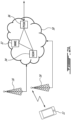
Figure 1 is block diagram of a tunnel filtering system in accordance with an illustrative embodiment of the present invention; -
Figure 2A is a block diagram of a wireless network in accordance with an illustrative embodiment of the present invention; -
Figure 2B is a flow chart of a bearer setup procedure in accordance with an illustrative embodiment of the present invention; and -
Figure 3 is a schematic diagram of a tunnel filtering system in accordance with an illustrative embodiment of the present invention. - Referring now to
Figure 1 , a tunnel filtering system in accordance with an illustrative embodiment of the present invention, and generally referred to using thereference numeral 10, will now be described. The System comprises a plurality of mobile devices/user equipment (UE) 12 which communicate via awireless communication network 14, such as GSM, 3GPP, 4G LTE or the like. In one embodiment thewireless network 14 provides data communications via a plurality ofbase stations 16/wireless network 18, such as an LTE network or the like, connected to a Wide Area Network (WAN) such as the Internet 20 for one or moremobile applications 22 running on the UE 12 and such that themobile application 22 can communicate with one of a plurality ofapplication servers 24 which is situated remote from the UE 12 and on which is running aserver application 26. Typically, this is done using TCP/IP and the like which support inter alia the establishment of a TCP/IP connection 28 for transmission of data between themobile application 22 and theapplication server 24. The mobile device/UE 12 illustratively comprises a microprocessor or the like (not shown) and the one ormobile applications 22 are stored in a computer readable storage medium (also not shown) on theUE 12 for execution as a process by the microprocessor. In a particular embodiment theapplication server 24 may comprise astorage repository 30 comprising data which may be accessed by themobile application 22. - Referring now to
Figure 2A in addition toFigure 1 , thewireless network 18 comprises inter alia three (3) components which work in concert to establish and maintain connections for UEs 12 and such that they can communicate withapplication servers 24 and the like via the Internet 20: A Mobility Management Entity (MME) 32; a Serving Gateway (SGW) 34; and a Packet Data Network Gateway (PGW) 36. The MME is a control node which manages thewireless network 18 by providing for UE authentication, orchestrating handovers between different LTE networks, and bearer management. The SGW 34 provides an interface towards the UEs 12 via thebase stations 16. The SGW 34 is responsible for handovers between neighbouringbase stations 16 as well as for data transfer. Each SGW 34 also monitors and maintains context information related to a UE 12 during a UE's idle state and generates paging requests when downlinked data is received from the UE 12. The PGW 36 provides the interconnection with external data networks such as the Internet 20. The PGW 36 manages policy enforcement, packet filtering, provides billing support and the like. The PGW 36 also allocates IP addresses to the UEs 12. - Referring now to
Figure 2B in addition toFigure 1 , in order to exchange data between amobile application 22 running on the UE 12 and aserver application 26 running on theApplication Server 24, an end-to-end type connection 38 is established between the UE 12 and theApplication Server 24. In a particular embodiment at least a portion of thisconnection 24 comprises a Virtual Private Network (VPN) type connection which allows data to be transmitted between the UE 12 and the Application Server24 in a secure fashion. As will be understood by a person of ordinary skill in the art, in a particular embodiment the point of termination of the VPN at theApplication Server 24 side may be at a corporate gateway or the like (not shown) which provides for example an interface between theApplication Server 24 and the Internet 20. - Still referring to
Figure 2B in addition toFigure 1 , other layers in the UE protocol stack are used to support the transmission of data via the end-to-end connection. Indeed, data packets which are transmitted via the end-to-end connection are transmitted between the UE 12 and the PGW 36 via one or more Evolved Packet System (EPS)bearers 40 and in turn transmitted between the UE 12 and the SGW 34 via an Enhanced Radio Access Bearer (E-RAB) 42. Similarly, data transmitted via the E-RAB 42 are transmitted between the UE 12 and thebase station 16 via aradio bearer 44. Additional systeminternal signalling bearers external bearers 50 for communicating via the Internet 20. - Still referring to
Figure 2B in addition toFigure 1 , in order to establish a communication path (or attach to the wireless network 18), for example on power up of the UE 12, using system information received from the base station 16 a UE 12 establishes a Radio Resource Control (RRC) connection to thebase station 16 via theradio bearer 44. Thebase station 16 also communicates with theMME 32 in order to authenticate the UE 12. Once the UE 12 is authenticated by the MME 32 adefault EPS bearer 40 is established between the UE 12 and the PGW 36. Thedefault EPS bearer 40 is assigned an IP address by the PGW 36. A default EPS bearer is assigned when the UE 12 attaches to thewireless network 18 for the first time, and is maintained as long as UE 12 is attached to thewireless network 18. The default EPS bearer provides a best effort service in that bit rate is not guaranteed. Of note is that a UE 12 may have additionaldefault EPS bearers 40 which are identified using their own IP addresses. Additional default EPS bearers can be useful in situations where different type of communications require a different delivery network to be accessed by the PGW 36, such as Internet Messaging Service (IMS) traffic on a first default EPS bearer and other Internet traffic on a second default EPS bearer. - Still referring to
Figure 2B , once attached eachEPS bearer 40 provides a virtual connection between theUE 12 and the PGW 36 and provides a data transmission service to which may be associated one or more quality of service (QoS) parameters, such as QoS Class Identifier (QCI), Allocation and Retention Priority (ARP), Guaranteed Bit Rate (GBR) and Aggregate Maximum Bit Rate (AMBR). - Still referring to
Figure 2B , In addition to thedefault EPS bearer 40, otherdedicated EPS bearers 40 can be established between the UE 12 and the PGW 36 and to each of which may be assigned a different set of QoS parameters. Each of thededicated EPS bearers 40 has the same IP address as the default EPS bearer 40 (although in a particular embodiment additionaldefault EPS bearers 40 may be established having a different IP address). The DedicatedEPS bearers 40 are typically used to provide a dedicated communication tunnel between UE 12 and PGW 36 to which is dedicated a particular type of traffic, such as Voice Over IP (VOIP), streaming video or the like. A typical set ofEPS bearers 40 might include one (1) default EPS bearer and eight (8) dedicated EPS bearers each assigned a unique QCI as follows:EPS Bearer QCI Resource Type Priority Packet Delay Budget (ms) Packet Error Loss Rate Example Default 9 Non-GBR 9 300 10-6 TCP Based Dedicated 1 8 Non-GBR 8 300 10-6 TCP Based Dedicated 2 7 Non-GBR 7 100 10-3 Voice, Video, interactive gaming Dedicated 3 6 Non-GBR 6 300 10-6 Video Dedicated 4 5 Non-GBR 1 100 10-6 IMS Signalling Dedicated 5 4 GBR 5 300 10-6 Buffered streaming Dedicated 6 3 GBR 3 50 10-3 Real-time gaming Dedicated 7 2 GBR 4 150 10-3 Live streaming Dedicated 8 1 GBR 2 100 10-2 Conversational voice - Referring now to
Figure 3 , as discussed above, theEPS bearers 40 can be used to support one ormore VPN tunnels 50 established between aVPN client 52 executing on theUE 12 and aVPN gateway 54, for example located within acorporate network 56 or the like. As known in the art a VPN inter alia allows data to be encrypted betweenVPN Client 52 andVPN gateway 54 such that users can securely share data via unsecured public networks such as theInternet 20 and WiFi or the like. In a particular embodiment, and as will be described in more detail below, when amobile application 22 wishes to communicate securely with anapplication server 24 via aVPN tunnel 50, theVPN client 52 establishes a plurality ofVPN tunnels 50, one for eachEPS bearer 40 interconnecting theUE 12 to thePGW 36. The VPN tunnels are established using the IP address assigned to theUE 12 by thePGW 36, the IP address of theVPN Gateway 54 and a knownport 58 for each VPN tunnel.Illustratively port 4500 is assigned to theVPN tunnel 50 which is assigned to thedefault EPS bearer 40,port 4501 is assigned to theEPS bearer 40 associated with QCI 1, port 4502 is assigned to theEPS bearer 40 associated withQCI 2, and so on. This port is the same at both theVPN client 52 and theVPN gateway 54. As known in the art, and for example when using the Internet Protocol Security (IPSec) network protocol suite, aVPN tunnel 50 is established between theVPN client 52 and theVPN gateway 54 through mutual authentication and the negotiation of cryptographic keys (not shown), for example using Internet Key Exchange (IKE and IKEv2) which are used subsequently during any communication session to encrypt and decrypt transmitted data. - Still referring to
Figure 3 , in order to control the type of data communications/application 22 which may use a given one of theVPN tunnels 50, aconfiguration file 60 is shared between theVPN client 52 and theVPN gateway 54. Theconfiguration file 60 comprises filters which are shared by afirst routing function 62 in theUE 12 and asecond routing function 64 in the gateway to associate a given data type for transmission via a givenVPN tunnel 50. Theconfiguration file 60 may be updated from time to time in order to redefine which data type may use whichVPN tunnel 50. As such, afirst application 22 communicating data of a first type with afirst server application 24 via afirst VPN tunnel 50 usingdedicated EPS bearer 40 havingQCI 8 may be redirected using an updatedconfiguration file 60 to asecond VPN tunnel 50 using a differentdedicated EPS bearer 40 havingQCI 9, thereby allowing theEPS bearer 40 havingQCI 8 and the first VPN tunnel to be dropped without affecting secure transmission of data from thefirst application 22 to thefirst server application 24. - Still referring to
Figure 3 , in a particular embodiment at least one of saidEPS bearers 40, and therefore its associatedVPN tunnel 50, is dropped in response to network congestion.
Claims (6)
- A tunnel filtering system (10) comprising:a wireless network comprising at least one base station (16) and a packet data network gateway (36) interconnecting said wireless network to a public network (20);at least one user equipment (12) comprising a Virtual Private Network, VPN, client (52) and at least one mobile application (22);a wireless radio connection (14) interconnecting said at least user equipment and said base station;an EPS session interconnecting each of said at least one user equipment and said packet data network gateway via said wireless radio connection, each of said of EPS sessions being identified by an IP address of said interconnected user equipment wherein each of said EPS sessions comprises a default EPS bearer (40) and a plurality of dedicated EPS bearers (40) identified by an EPS bearer ID;a VPN gateway (54) connected to said public network and comprising a gateway IP address; andat least one application server (24) comprising at least one server application (26);whereina plurality of VPN tunnels (50) interconnect each of said VPN client with said VPN gateway, each of said VPN tunnels comprising a user equipment IP address, a VPN gateway IP address and a known port (58), wherein data transmission via one of said VPN tunnels is supported by an associated one of said EPS bearers; anda set of filters (60) are shared between a first routing function in each of said at least one user device and a second routing function in said VPN gateway, each of said filters being used by said first and second routing functions to direct a particular one of a plurality of data types to a first specified one of said plurality of VPN tunnels;wherein a communicating one of said at least one mobile application communicates data of said particular data type with a communicating one of said at least one server application via said first specified VPN tunnel and a first associated EPS bearer and further wherein when said first associated EPS bearer and said first specified VPN tunnel are no longer available, at least one of said filters is modified such that said particular data type is associated with a second specified one of said VPN tunnels wherein said communicating mobile application communicates said data of said particular data type subsequently with said communicating server application via said second specified VPN tunnel and a second associated EPS bearer.
- The tunnel filtering system of Claim 1, wherein said first associated EPS bearer and said specified VPN tunnel are no longer available due to congestion.
- The tunnel filtering system of Claim 1, comprising a plurality of said at least one mobile application and wherein each of said plurality of mobile applications transmits data of a different one of said data types and via a different one of said VPN tunnels.
- A method for securely interconnecting at least one mobile application (22) executing on a mobile device (12) comprising a Virtual Private Network, VPN, client (52) with an application server (24) via a wireless radio connection (14) established between the mobile device and a base station (16) of a wireless network comprising a packet data network gateway (36) interconnecting said wireless network to a public network (20) comprising a VPN gateway (54) comprising a gateway IP address, wherein the method comprises:opening an EPS session interconnecting the mobile device and the packet data network gateway via the wireless radio connection, each of said EPS sessions being identified by an IP address of the interconnected user equipment wherein each of said EPS sessions comprises a default EPS bearer (40) and a plurality of dedicated EPS bearers (40) identified by an EPS bearer ID;establishing a plurality of VPN tunnels (50) between the VPN client and the VPN gateway, each of said VPN tunnels comprising a user equipment IP address, the gateway IP address and a known port (58) wherein data transmission via one of said VPN tunnels is provided between the mobile device and the packet data network gateway by a respective one of the EPS bearers;sharing a set of filters (60) between a first routing function in the mobile device and a second routing function in the VPN gateway, each of said filters being used by said first and second routing functions to direct a particular data type to a first specified one of said plurality of VPN tunnels;transmitting data of said particular data type between the mobile application and the application server using said first specified VPN tunnel;modifying at least one of said filters such that said particular data type is directed to a second specified one of said VPN tunnels; andtransmitting data of said particular data type between the mobile application and the application server using said second specified VPN tunnel.
- The method of Claim 4, further comprising, prior to said opening act, the act of authenticating the mobile device via the wireless network.
- A non-transitory computer readable medium storing a program causing a microprocessor to execute a process on a mobile device (12) comprising a storage device, a Virtual Private Network, VPN, client (52) with an application server (24) via a wireless radio connection established between the mobile device and a base station (16) of a wireless network comprising a packet data network gateway (36) interconnecting said wireless network to a public network (20) comprising a VPN gateway (54) comprising a gateway IP address, wherein the process comprises:opening an EPS session interconnecting the mobile device and the packet data network gateway via the wireless radio connection, each of said EPS sessions being identified by an IP address of the interconnected user equipment wherein each of said EPS session comprises a default EPS bearer (40) and a plurality of dedicated EPS bearers (40) identified by an EPS bearer ID;establishing a plurality of Virtual Private Network, VPN, tunnels (50) between the VPN client and the VPN gateway, each of said VPN tunnels comprising a user equipment IP address, the gateway IP address and a known port (58) wherein data transmission via one of said VPN tunnels is provided between the mobile device and the packet data network gateway by a respective one of the EPS bearers;storing a set of shared filters (60) in the storage device, each of said filters directing a particular data type to a first specified one of said plurality of VPN tunnels;routing data of said particular data type for transmission between the mobile application and the application server according to said filters to said first specified VPN tunnel;modifying at least one of said filters such that said particular data type is directed to a second specified one of said VPN tunnels; androuting data of said particular data type for transmission between the mobile application and the application server according to said filters to said second specified VPN tunnel.
Applications Claiming Priority (2)
| Application Number | Priority Date | Filing Date | Title |
|---|---|---|---|
| US201762607440P | 2017-12-19 | 2017-12-19 | |
| PCT/CA2018/051622 WO2019119130A1 (en) | 2017-12-19 | 2018-12-19 | Tunnel filtering system and method |
Publications (3)
| Publication Number | Publication Date |
|---|---|
| EP3729907A1 EP3729907A1 (en) | 2020-10-28 |
| EP3729907A4 EP3729907A4 (en) | 2021-08-25 |
| EP3729907B1 true EP3729907B1 (en) | 2025-04-16 |
Family
ID=66992436
Family Applications (1)
| Application Number | Title | Priority Date | Filing Date |
|---|---|---|---|
| EP18891113.5A Active EP3729907B1 (en) | 2017-12-19 | 2018-12-19 | Tunnel filtering system and method |
Country Status (2)
| Country | Link |
|---|---|
| EP (1) | EP3729907B1 (en) |
| WO (1) | WO2019119130A1 (en) |
Families Citing this family (14)
| Publication number | Priority date | Publication date | Assignee | Title |
|---|---|---|---|---|
| US12120024B2 (en) * | 2020-11-02 | 2024-10-15 | Google Llc | Virtual carrier network |
| US12057219B2 (en) | 2021-07-22 | 2024-08-06 | Cilag Gmbh International | Surgical data processing and metadata annotation |
| US12592312B2 (en) | 2021-07-22 | 2026-03-31 | Cilag Gmbh International | Surgical data system and control |
| US11601232B2 (en) | 2021-07-22 | 2023-03-07 | Cilag Gmbh International | Redundant communication channels and processing of imaging feeds |
| US12482555B2 (en) | 2021-07-22 | 2025-11-25 | Cilag Gmbh International | Surgical data system and classification |
| US11783938B2 (en) | 2021-07-22 | 2023-10-10 | Cilag Gmbh International | Integrated hub systems control interfaces and connections |
| US12154682B2 (en) | 2021-07-22 | 2024-11-26 | Cilag Gmbh International | Monitoring power utilization and needs within surgical systems |
| US12068068B2 (en) | 2021-07-22 | 2024-08-20 | Cilag Gmbh International | Cooperative composite video streams layered onto the surgical site and instruments |
| US12462925B2 (en) | 2021-07-22 | 2025-11-04 | Cilag Gmbh International | Location and surgical procedure specific data storage and retrieval |
| US12154683B2 (en) | 2021-07-22 | 2024-11-26 | Cilag Gmbh International | Intercommunication and cooperative operation of surgical devices |
| US12046358B2 (en) | 2021-07-22 | 2024-07-23 | Cilag Gmbh International | Configuration of the display settings and displayed information based on the recognition of the user(s) and awareness of procedure, location or usage |
| US12260953B2 (en) * | 2021-07-22 | 2025-03-25 | Cilag Gmbh International | Detection of surgical devices within surgical systems |
| US12205712B2 (en) | 2021-07-22 | 2025-01-21 | Cilag Gmbh International | Method of surgical system power management, communication, processing, storage and display |
| CN121241551A (en) * | 2023-04-12 | 2025-12-30 | 瑞典爱立信有限公司 | Application-level service quality control |
Family Cites Families (5)
| Publication number | Priority date | Publication date | Assignee | Title |
|---|---|---|---|---|
| US8873398B2 (en) | 2011-05-23 | 2014-10-28 | Telefonaktiebolaget L M Ericsson (Publ) | Implementing EPC in a cloud computer with openflow data plane |
| US8923863B2 (en) * | 2011-12-19 | 2014-12-30 | Cisco Technology, Inc. | Maintaining signaling reduction mode in communication networks |
| US9357431B2 (en) | 2012-08-31 | 2016-05-31 | Qualcomm Incorporated | Selective network parameter configuratons based on network identification of non-IMS multimedia applications |
| US10187357B2 (en) * | 2015-07-05 | 2019-01-22 | M2MD Technologies, Inc. | Method and system for internetwork communication with machine devices |
| US9894103B2 (en) * | 2015-08-28 | 2018-02-13 | Nicira, Inc. | Performing source network address translation based on remote device management attributes |
-
2018
- 2018-12-19 WO PCT/CA2018/051622 patent/WO2019119130A1/en not_active Ceased
- 2018-12-19 EP EP18891113.5A patent/EP3729907B1/en active Active
Also Published As
| Publication number | Publication date |
|---|---|
| EP3729907A4 (en) | 2021-08-25 |
| EP3729907A1 (en) | 2020-10-28 |
| WO2019119130A1 (en) | 2019-06-27 |
Similar Documents
| Publication | Publication Date | Title |
|---|---|---|
| EP3729907A1 (en) | Tunnel filtering system and method | |
| US11695742B2 (en) | Security implementation method, device, and system | |
| CN112930691B (en) | System and method for security protection of NAS messages | |
| USRE48631E1 (en) | Method and system for selective protection of data exchanged between user equipment and network | |
| US9992705B2 (en) | Wi-Fi calling quality of service on trusted WLAN networks | |
| US20250310429A1 (en) | Communicating pdu sets in a wireless communication system | |
| JP6907261B2 (en) | Improved priority handling for data flow transport in communication systems | |
| US10484910B2 (en) | Traffic flow splitting method and apparatus | |
| WO2018000867A1 (en) | Method and apparatus for configuring key and determining security policy | |
| US11882105B2 (en) | Authentication system when authentication is not functioning | |
| Atayero et al. | 3GPP long term evolution: Architecture, protocols and interfaces | |
| CN105916218A (en) | Integrated base station system and communication method based on same | |
| US11882445B2 (en) | Authentication system | |
| US10595349B2 (en) | Quality of service in neural host network | |
| US20250132942A1 (en) | Managing reception of multicast and broadcast services | |
| US12574723B2 (en) | Early data communication in an inactive state | |
| US20240147568A1 (en) | Managing early data communication | |
| KR20140005024A (en) | Method for packet barring in lte mobile communication system and, system therefor | |
| CN103391270B (en) | Method, equipment and the system that a kind of data process | |
| WO2025208161A1 (en) | Handling encrypted xrm traffic using quic aware proxying | |
| Said | Contextual Connectivity in Multi-Access Architectures | |
| Everett et al. | Priority service for CSfC secure mobile communication over LTE networks for national security and emergency preparedness |
Legal Events
| Date | Code | Title | Description |
|---|---|---|---|
| STAA | Information on the status of an ep patent application or granted ep patent |
Free format text: STATUS: THE INTERNATIONAL PUBLICATION HAS BEEN MADE |
|
| PUAI | Public reference made under article 153(3) epc to a published international application that has entered the european phase |
Free format text: ORIGINAL CODE: 0009012 |
|
| STAA | Information on the status of an ep patent application or granted ep patent |
Free format text: STATUS: REQUEST FOR EXAMINATION WAS MADE |
|
| 17P | Request for examination filed |
Effective date: 20200719 |
|
| AK | Designated contracting states |
Kind code of ref document: A1 Designated state(s): AL AT BE BG CH CY CZ DE DK EE ES FI FR GB GR HR HU IE IS IT LI LT LU LV MC MK MT NL NO PL PT RO RS SE SI SK SM TR |
|
| AX | Request for extension of the european patent |
Extension state: BA ME |
|
| DAV | Request for validation of the european patent (deleted) | ||
| DAX | Request for extension of the european patent (deleted) | ||
| A4 | Supplementary search report drawn up and despatched |
Effective date: 20210727 |
|
| RIC1 | Information provided on ipc code assigned before grant |
Ipc: H04W 12/03 20210101AFI20210721BHEP Ipc: H04W 12/088 20210101ALI20210721BHEP Ipc: H04L 29/06 20060101ALI20210721BHEP Ipc: H04W 76/12 20180101ALI20210721BHEP Ipc: H04W 28/10 20090101ALI20210721BHEP Ipc: H04W 28/12 20090101ALI20210721BHEP Ipc: H04W 28/02 20090101ALI20210721BHEP |
|
| REG | Reference to a national code |
Ref country code: DE Ref legal event code: R079 Free format text: PREVIOUS MAIN CLASS: H04W0076120000 Ipc: H04W0012030000 Ref country code: DE Ref legal event code: R079 Ref document number: 602018081216 Country of ref document: DE Free format text: PREVIOUS MAIN CLASS: H04W0076120000 Ipc: H04W0012030000 |
|
| GRAP | Despatch of communication of intention to grant a patent |
Free format text: ORIGINAL CODE: EPIDOSNIGR1 |
|
| STAA | Information on the status of an ep patent application or granted ep patent |
Free format text: STATUS: GRANT OF PATENT IS INTENDED |
|
| RIC1 | Information provided on ipc code assigned before grant |
Ipc: H04L 9/40 20220101ALI20241031BHEP Ipc: H04W 28/02 20090101ALI20241031BHEP Ipc: H04W 28/12 20090101ALI20241031BHEP Ipc: H04W 28/10 20090101ALI20241031BHEP Ipc: H04W 76/12 20180101ALI20241031BHEP Ipc: H04W 12/088 20210101ALI20241031BHEP Ipc: H04W 12/03 20210101AFI20241031BHEP |
|
| INTG | Intention to grant announced |
Effective date: 20241115 |
|
| GRAS | Grant fee paid |
Free format text: ORIGINAL CODE: EPIDOSNIGR3 |
|
| GRAA | (expected) grant |
Free format text: ORIGINAL CODE: 0009210 |
|
| STAA | Information on the status of an ep patent application or granted ep patent |
Free format text: STATUS: THE PATENT HAS BEEN GRANTED |
|
| AK | Designated contracting states |
Kind code of ref document: B1 Designated state(s): AL AT BE BG CH CY CZ DE DK EE ES FI FR GB GR HR HU IE IS IT LI LT LU LV MC MK MT NL NO PL PT RO RS SE SI SK SM TR |
|
| REG | Reference to a national code |
Ref country code: GB Ref legal event code: FG4D |
|
| REG | Reference to a national code |
Ref country code: CH Ref legal event code: EP |
|
| REG | Reference to a national code |
Ref country code: IE Ref legal event code: FG4D |
|
| REG | Reference to a national code |
Ref country code: DE Ref legal event code: R096 Ref document number: 602018081216 Country of ref document: DE |
|
| REG | Reference to a national code |
Ref country code: NL Ref legal event code: MP Effective date: 20250416 |
|
| PG25 | Lapsed in a contracting state [announced via postgrant information from national office to epo] |
Ref country code: NL Free format text: LAPSE BECAUSE OF FAILURE TO SUBMIT A TRANSLATION OF THE DESCRIPTION OR TO PAY THE FEE WITHIN THE PRESCRIBED TIME-LIMIT Effective date: 20250416 |
|
| REG | Reference to a national code |
Ref country code: AT Ref legal event code: MK05 Ref document number: 1786689 Country of ref document: AT Kind code of ref document: T Effective date: 20250416 |
|
| PG25 | Lapsed in a contracting state [announced via postgrant information from national office to epo] |
Ref country code: FI Free format text: LAPSE BECAUSE OF FAILURE TO SUBMIT A TRANSLATION OF THE DESCRIPTION OR TO PAY THE FEE WITHIN THE PRESCRIBED TIME-LIMIT Effective date: 20250416 Ref country code: PT Free format text: LAPSE BECAUSE OF FAILURE TO SUBMIT A TRANSLATION OF THE DESCRIPTION OR TO PAY THE FEE WITHIN THE PRESCRIBED TIME-LIMIT Effective date: 20250818 Ref country code: ES Free format text: LAPSE BECAUSE OF FAILURE TO SUBMIT A TRANSLATION OF THE DESCRIPTION OR TO PAY THE FEE WITHIN THE PRESCRIBED TIME-LIMIT Effective date: 20250416 |
|
| REG | Reference to a national code |
Ref country code: LT Ref legal event code: MG9D |
|
| PG25 | Lapsed in a contracting state [announced via postgrant information from national office to epo] |
Ref country code: NO Free format text: LAPSE BECAUSE OF FAILURE TO SUBMIT A TRANSLATION OF THE DESCRIPTION OR TO PAY THE FEE WITHIN THE PRESCRIBED TIME-LIMIT Effective date: 20250716 Ref country code: GR Free format text: LAPSE BECAUSE OF FAILURE TO SUBMIT A TRANSLATION OF THE DESCRIPTION OR TO PAY THE FEE WITHIN THE PRESCRIBED TIME-LIMIT Effective date: 20250717 |
|
| PG25 | Lapsed in a contracting state [announced via postgrant information from national office to epo] |
Ref country code: PL Free format text: LAPSE BECAUSE OF FAILURE TO SUBMIT A TRANSLATION OF THE DESCRIPTION OR TO PAY THE FEE WITHIN THE PRESCRIBED TIME-LIMIT Effective date: 20250416 |
|
| PG25 | Lapsed in a contracting state [announced via postgrant information from national office to epo] |
Ref country code: BG Free format text: LAPSE BECAUSE OF FAILURE TO SUBMIT A TRANSLATION OF THE DESCRIPTION OR TO PAY THE FEE WITHIN THE PRESCRIBED TIME-LIMIT Effective date: 20250416 |
|
| PG25 | Lapsed in a contracting state [announced via postgrant information from national office to epo] |
Ref country code: HR Free format text: LAPSE BECAUSE OF FAILURE TO SUBMIT A TRANSLATION OF THE DESCRIPTION OR TO PAY THE FEE WITHIN THE PRESCRIBED TIME-LIMIT Effective date: 20250416 |
|
| PG25 | Lapsed in a contracting state [announced via postgrant information from national office to epo] |
Ref country code: AT Free format text: LAPSE BECAUSE OF FAILURE TO SUBMIT A TRANSLATION OF THE DESCRIPTION OR TO PAY THE FEE WITHIN THE PRESCRIBED TIME-LIMIT Effective date: 20250416 |
|
| PG25 | Lapsed in a contracting state [announced via postgrant information from national office to epo] |
Ref country code: RS Free format text: LAPSE BECAUSE OF FAILURE TO SUBMIT A TRANSLATION OF THE DESCRIPTION OR TO PAY THE FEE WITHIN THE PRESCRIBED TIME-LIMIT Effective date: 20250716 |
|
| PG25 | Lapsed in a contracting state [announced via postgrant information from national office to epo] |
Ref country code: IS Free format text: LAPSE BECAUSE OF FAILURE TO SUBMIT A TRANSLATION OF THE DESCRIPTION OR TO PAY THE FEE WITHIN THE PRESCRIBED TIME-LIMIT Effective date: 20250816 |
|
| PG25 | Lapsed in a contracting state [announced via postgrant information from national office to epo] |
Ref country code: LV Free format text: LAPSE BECAUSE OF FAILURE TO SUBMIT A TRANSLATION OF THE DESCRIPTION OR TO PAY THE FEE WITHIN THE PRESCRIBED TIME-LIMIT Effective date: 20250416 |
|
| PGFP | Annual fee paid to national office [announced via postgrant information from national office to epo] |
Ref country code: GB Payment date: 20251222 Year of fee payment: 8 |
|
| PG25 | Lapsed in a contracting state [announced via postgrant information from national office to epo] |
Ref country code: SM Free format text: LAPSE BECAUSE OF FAILURE TO SUBMIT A TRANSLATION OF THE DESCRIPTION OR TO PAY THE FEE WITHIN THE PRESCRIBED TIME-LIMIT Effective date: 20250416 Ref country code: DK Free format text: LAPSE BECAUSE OF FAILURE TO SUBMIT A TRANSLATION OF THE DESCRIPTION OR TO PAY THE FEE WITHIN THE PRESCRIBED TIME-LIMIT Effective date: 20250416 |
|
| PGFP | Annual fee paid to national office [announced via postgrant information from national office to epo] |
Ref country code: FR Payment date: 20251223 Year of fee payment: 8 |
|
| REG | Reference to a national code |
Ref country code: DE Ref legal event code: R097 Ref document number: 602018081216 Country of ref document: DE |
|
| PG25 | Lapsed in a contracting state [announced via postgrant information from national office to epo] |
Ref country code: CZ Free format text: LAPSE BECAUSE OF FAILURE TO SUBMIT A TRANSLATION OF THE DESCRIPTION OR TO PAY THE FEE WITHIN THE PRESCRIBED TIME-LIMIT Effective date: 20250416 |
|
| PG25 | Lapsed in a contracting state [announced via postgrant information from national office to epo] |
Ref country code: EE Free format text: LAPSE BECAUSE OF FAILURE TO SUBMIT A TRANSLATION OF THE DESCRIPTION OR TO PAY THE FEE WITHIN THE PRESCRIBED TIME-LIMIT Effective date: 20250416 |
|
| PG25 | Lapsed in a contracting state [announced via postgrant information from national office to epo] |
Ref country code: SK Free format text: LAPSE BECAUSE OF FAILURE TO SUBMIT A TRANSLATION OF THE DESCRIPTION OR TO PAY THE FEE WITHIN THE PRESCRIBED TIME-LIMIT Effective date: 20250416 Ref country code: RO Free format text: LAPSE BECAUSE OF FAILURE TO SUBMIT A TRANSLATION OF THE DESCRIPTION OR TO PAY THE FEE WITHIN THE PRESCRIBED TIME-LIMIT Effective date: 20250416 |
|
| PG25 | Lapsed in a contracting state [announced via postgrant information from national office to epo] |
Ref country code: IT Free format text: LAPSE BECAUSE OF FAILURE TO SUBMIT A TRANSLATION OF THE DESCRIPTION OR TO PAY THE FEE WITHIN THE PRESCRIBED TIME-LIMIT Effective date: 20250416 |
|
| PLBE | No opposition filed within time limit |
Free format text: ORIGINAL CODE: 0009261 |
|
| STAA | Information on the status of an ep patent application or granted ep patent |
Free format text: STATUS: NO OPPOSITION FILED WITHIN TIME LIMIT |
|
| REG | Reference to a national code |
Ref country code: CH Ref legal event code: L10 Free format text: ST27 STATUS EVENT CODE: U-0-0-L10-L00 (AS PROVIDED BY THE NATIONAL OFFICE) Effective date: 20260225 |
|
| 26N | No opposition filed |
Effective date: 20260119 |
|
| PGFP | Annual fee paid to national office [announced via postgrant information from national office to epo] |
Ref country code: DE Payment date: 20251230 Year of fee payment: 8 |