EP3729592B1 - Improvements relating to current injection in wind power plants - Google Patents
Improvements relating to current injection in wind power plants Download PDFInfo
- Publication number
- EP3729592B1 EP3729592B1 EP18811438.3A EP18811438A EP3729592B1 EP 3729592 B1 EP3729592 B1 EP 3729592B1 EP 18811438 A EP18811438 A EP 18811438A EP 3729592 B1 EP3729592 B1 EP 3729592B1
- Authority
- EP
- European Patent Office
- Prior art keywords
- voltage
- injection profile
- current
- point
- grid
- Prior art date
- Legal status (The legal status is an assumption and is not a legal conclusion. Google has not performed a legal analysis and makes no representation as to the accuracy of the status listed.)
- Active
Links
Images




Classifications
-
- H—ELECTRICITY
- H02—GENERATION; CONVERSION OR DISTRIBUTION OF ELECTRIC POWER
- H02J—ELECTRIC POWER NETWORKS; CIRCUIT ARRANGEMENTS OR SYSTEMS FOR SUPPLYING OR DISTRIBUTING ELECTRIC POWER; SYSTEMS FOR STORING ELECTRIC ENERGY
- H02J3/00—Circuit arrangements for AC mains or AC distribution networks
- H02J3/12—Arrangements for adjusting voltage in AC networks by changing a characteristic of the network load
- H02J3/16—Arrangements for adjusting voltage in AC networks by changing a characteristic of the network load by adjustment of reactive power
-
- F—MECHANICAL ENGINEERING; LIGHTING; HEATING; WEAPONS; BLASTING
- F03—MACHINES OR ENGINES FOR LIQUIDS; WIND, SPRING, OR WEIGHT MOTORS; PRODUCING MECHANICAL POWER OR A REACTIVE PROPULSIVE THRUST, NOT OTHERWISE PROVIDED FOR
- F03D—WIND MOTORS
- F03D7/00—Controlling wind motors
- F03D7/02—Controlling wind motors the wind motors having rotation axis substantially parallel to the air flow entering the rotor
- F03D7/028—Controlling wind motors the wind motors having rotation axis substantially parallel to the air flow entering the rotor controlling wind motor output power
- F03D7/0284—Controlling wind motors the wind motors having rotation axis substantially parallel to the air flow entering the rotor controlling wind motor output power in relation to the state of the electric grid
-
- H—ELECTRICITY
- H02—GENERATION; CONVERSION OR DISTRIBUTION OF ELECTRIC POWER
- H02J—ELECTRIC POWER NETWORKS; CIRCUIT ARRANGEMENTS OR SYSTEMS FOR SUPPLYING OR DISTRIBUTING ELECTRIC POWER; SYSTEMS FOR STORING ELECTRIC ENERGY
- H02J13/00—Circuit arrangements for providing remote monitoring or remote control of equipment in a power distribution network
- H02J13/12—Monitoring network conditions, e.g. electrical magnitudes or operational status
-
- H—ELECTRICITY
- H02—GENERATION; CONVERSION OR DISTRIBUTION OF ELECTRIC POWER
- H02J—ELECTRIC POWER NETWORKS; CIRCUIT ARRANGEMENTS OR SYSTEMS FOR SUPPLYING OR DISTRIBUTING ELECTRIC POWER; SYSTEMS FOR STORING ELECTRIC ENERGY
- H02J13/00—Circuit arrangements for providing remote monitoring or remote control of equipment in a power distribution network
- H02J13/13—Circuit arrangements for providing remote monitoring or remote control of equipment in a power distribution network characterised by the transmission of data to equipment in the power network
-
- H—ELECTRICITY
- H02—GENERATION; CONVERSION OR DISTRIBUTION OF ELECTRIC POWER
- H02J—ELECTRIC POWER NETWORKS; CIRCUIT ARRANGEMENTS OR SYSTEMS FOR SUPPLYING OR DISTRIBUTING ELECTRIC POWER; SYSTEMS FOR STORING ELECTRIC ENERGY
- H02J3/00—Circuit arrangements for AC mains or AC distribution networks
- H02J3/001—Arrangements for handling faults or abnormalities, e.g. emergencies or contingencies
-
- H—ELECTRICITY
- H02—GENERATION; CONVERSION OR DISTRIBUTION OF ELECTRIC POWER
- H02J—ELECTRIC POWER NETWORKS; CIRCUIT ARRANGEMENTS OR SYSTEMS FOR SUPPLYING OR DISTRIBUTING ELECTRIC POWER; SYSTEMS FOR STORING ELECTRIC ENERGY
- H02J3/00—Circuit arrangements for AC mains or AC distribution networks
- H02J3/38—Arrangements for feeding a single network from two or more generators or sources in parallel; Arrangements for feeding already energised networks from additional generators or sources in parallel
- H02J3/381—Dispersed generators
-
- F—MECHANICAL ENGINEERING; LIGHTING; HEATING; WEAPONS; BLASTING
- F05—INDEXING SCHEMES RELATING TO ENGINES OR PUMPS IN VARIOUS SUBCLASSES OF CLASSES F01-F04
- F05B—INDEXING SCHEME RELATING TO WIND, SPRING, WEIGHT, INERTIA OR LIKE MOTORS, TO MACHINES OR ENGINES FOR LIQUIDS COVERED BY SUBCLASSES F03B, F03D AND F03G
- F05B2270/00—Control
- F05B2270/10—Purpose of the control system
- F05B2270/107—Purpose of the control system to cope with emergencies
- F05B2270/1071—Purpose of the control system to cope with emergencies in particular sudden load loss
- F05B2270/10711—Purpose of the control system to cope with emergencies in particular sudden load loss applying a low voltage ride through method
-
- F—MECHANICAL ENGINEERING; LIGHTING; HEATING; WEAPONS; BLASTING
- F05—INDEXING SCHEMES RELATING TO ENGINES OR PUMPS IN VARIOUS SUBCLASSES OF CLASSES F01-F04
- F05B—INDEXING SCHEME RELATING TO WIND, SPRING, WEIGHT, INERTIA OR LIKE MOTORS, TO MACHINES OR ENGINES FOR LIQUIDS COVERED BY SUBCLASSES F03B, F03D AND F03G
- F05B2270/00—Control
- F05B2270/30—Control parameters, e.g. input parameters
- F05B2270/337—Electrical grid status parameters, e.g. voltage, frequency or power demand
-
- H—ELECTRICITY
- H02—GENERATION; CONVERSION OR DISTRIBUTION OF ELECTRIC POWER
- H02J—ELECTRIC POWER NETWORKS; CIRCUIT ARRANGEMENTS OR SYSTEMS FOR SUPPLYING OR DISTRIBUTING ELECTRIC POWER; SYSTEMS FOR STORING ELECTRIC ENERGY
- H02J2101/00—Supply or distribution of decentralised, dispersed or local electric power generation
- H02J2101/20—Dispersed power generation using renewable energy sources
- H02J2101/28—Wind energy
-
- H—ELECTRICITY
- H02—GENERATION; CONVERSION OR DISTRIBUTION OF ELECTRIC POWER
- H02J—ELECTRIC POWER NETWORKS; CIRCUIT ARRANGEMENTS OR SYSTEMS FOR SUPPLYING OR DISTRIBUTING ELECTRIC POWER; SYSTEMS FOR STORING ELECTRIC ENERGY
- H02J3/00—Circuit arrangements for AC mains or AC distribution networks
- H02J3/38—Arrangements for feeding a single network from two or more generators or sources in parallel; Arrangements for feeding already energised networks from additional generators or sources in parallel
- H02J3/46—Controlling the sharing of generated power between the generators, sources or networks
- H02J3/50—Controlling the sharing of reactive power
-
- Y—GENERAL TAGGING OF NEW TECHNOLOGICAL DEVELOPMENTS; GENERAL TAGGING OF CROSS-SECTIONAL TECHNOLOGIES SPANNING OVER SEVERAL SECTIONS OF THE IPC; TECHNICAL SUBJECTS COVERED BY FORMER USPC CROSS-REFERENCE ART COLLECTIONS [XRACs] AND DIGESTS
- Y02—TECHNOLOGIES OR APPLICATIONS FOR MITIGATION OR ADAPTATION AGAINST CLIMATE CHANGE
- Y02B—CLIMATE CHANGE MITIGATION TECHNOLOGIES RELATED TO BUILDINGS, e.g. HOUSING, HOUSE APPLIANCES OR RELATED END-USER APPLICATIONS
- Y02B90/00—Enabling technologies or technologies with a potential or indirect contribution to GHG emissions mitigation
- Y02B90/20—Smart grids as enabling technology in buildings sector
-
- Y—GENERAL TAGGING OF NEW TECHNOLOGICAL DEVELOPMENTS; GENERAL TAGGING OF CROSS-SECTIONAL TECHNOLOGIES SPANNING OVER SEVERAL SECTIONS OF THE IPC; TECHNICAL SUBJECTS COVERED BY FORMER USPC CROSS-REFERENCE ART COLLECTIONS [XRACs] AND DIGESTS
- Y04—INFORMATION OR COMMUNICATION TECHNOLOGIES HAVING AN IMPACT ON OTHER TECHNOLOGY AREAS
- Y04S—SYSTEMS INTEGRATING TECHNOLOGIES RELATED TO POWER NETWORK OPERATION, COMMUNICATION OR INFORMATION TECHNOLOGIES FOR IMPROVING THE ELECTRICAL POWER GENERATION, TRANSMISSION, DISTRIBUTION, MANAGEMENT OR USAGE, i.e. SMART GRIDS
- Y04S40/00—Systems for electrical power generation, transmission, distribution or end-user application management characterised by the use of communication or information technologies, or communication or information technology specific aspects supporting them
- Y04S40/12—Systems for electrical power generation, transmission, distribution or end-user application management characterised by the use of communication or information technologies, or communication or information technology specific aspects supporting them characterised by data transport means between the monitoring, controlling or managing units and monitored, controlled or operated electrical equipment
Definitions
- the present disclosure relates to a method of controlling a renewable energy power plant, to a renewable energy power plant controller, and to a wind turbine power plant more generally.
- a wind power plant typically comprises a plurality of wind turbine generators and is also known as a wind park or a wind farm.
- the regulation and general operation of the power plant is controlled by a power plant control system or controller (PPC), which implements operational limits and requirements as set out by a Transmission System Operator (TSO) or in country-specific grid interconnection requirements or 'grid codes'.
- PPC power plant control system
- TSO Transmission System Operator
- the TSO also communicates power delivery demands to the PPC, including active and/or reactive current delivery demands.
- Grid codes commonly include specific requirements for reactive and/or active current supply during a fault. These requirements ensure that the network is fully supported throughout the fault and that voltage level recovery is sustained by the active and/or reactive current supplied by the wind power plant or plants.
- One approach to ensure that the requirements are met during a fault is to estimate, prior to installation of the power plant, the required injection profile for each wind turbine generator.
- One example of this is based on a linear weighting, or 'K-factor', as described in the German Grid Code and standard EN 50549.
- the K-factor is used as only reactive current control is specified, while there are no requirements for active current.
- any change in grid condition or to the WPP may result in non-compliance.
- new requirements for active current would not be able to be implemented by current systems using only a K-factor.
- generating current injection profiles during normal operation facilitates the generation of more accurate injection profiles, due to the parameters available for monitoring.
- the operation of the generator according to those profiles during a grid fault results in immediate compliance with grid code requirements. This means that the power plant that the generator forms part of is able to support grid recovery immediately, reducing the likelihood of disconnection or damage to the system.
- Generating, during normal operating conditions at least one current injection profile may comprise calculating a voltage function.
- a voltage function beneficially ensures a straightforward calculation that can be made very quickly by a control system to achieve fast adoption of the correct output current level.
- the voltage function may comprise at least one weighting.
- the voltage function may require an input of the voltage measured at the point between the renewable energy generator and the low-voltage side of the transformer of the connecting network only.
- the point between the renewable energy generator and the low voltage transformer of the connecting network may be a terminal of the renewable energy generator.
- the current injection profile may be an active current injection profile.
- the current injection profile may be a reactive current injection profile.
- the voltage function may be a first order polynomial, a second order polynomial, a third order polynomial, a fourth order polynomial, or a polynomial of a higher order.
- Iteratively updating an injection profile further reduces the computational power required to implement this method, permitting its use in existing power plants and with existing generators.
- the step of generating, during normal operating conditions, at least one current injection profile may be performed at intervals while normal operating conditions persist, such that the injection profile is updated iteratively.
- the generation may be performed at intervals as requested by an external system, or according to a predetermined period, or when a change in a particular monitored parameter is identified.
- generating updated injection profiles through a period of normal operation results in an up-to-date profile when required, such that the output of the generator is compliant at the Point of Interconnection.
- the parameters comprise a voltage level measured at a point in the connecting network between the low-voltage side of the transformer and the renewable energy generator. It is to be understood that the voltage level should be measured sufficiently remote from the Point of Interconnection such that the measurement reflects the voltage level at a point in the connection network and not at the Point of Interconnection.
- the current set point may be based on grid code requirements.
- the method may comprise updating a stored current injection profile once a new current injection profile has been generated.
- a renewable energy power plant comprising a plurality of renewable energy generators and a control system for controlling the current output of the plurality of renewable energy generators, a connecting network including a transformer and connecting those renewable energy generators to a Point of Interconnection (Pol) with which the connecting network is connected to an external power grid, and measurement means configured to measure a voltage level at the Point of Interconnection and electrical parameters of the connecting network comprising the impedance of the connecting network and a voltage level at a point in the connecting network between a low-voltage side of the transformer and the renewable energy generators.
- a connecting network including a transformer and connecting those renewable energy generators to a Point of Interconnection (Pol) with which the connecting network is connected to an external power grid
- measurement means configured to measure a voltage level at the Point of Interconnection and electrical parameters of the connecting network comprising the impedance of the connecting network and a voltage level at a point in the connecting network between a low-voltage side of the transformer and the renewable energy generators.
- the control system is configured to: generate, during normal operating conditions, at least one current injection profile based upon the measured voltage level at the Point of Interconnection, the impedance of the connecting network and a predetermined injection profile, wherein the normal operating conditions is when the voltage level of the external power gird is within a normal operating band; and operate the renewable energy generators, during a grid fault, to output power according to the generated current injection profile and the voltage level measured at the point in the connecting network between the low-voltage side of the transformer and the renewable energy generators, such that the current level injected by the renewable energy generators to the connecting network results in a current set point being met at the Point of Interconnection, wherein grid fault is when the voltage level of the external power grid is outside the normal operating band.
- a computer program downloadable from a communication network and/or stored on a machine readable medium, comprising program code instructions which, when executed on a computer, cause the computer to implement a method as described above.
- FIG 1 illustrates a typical architecture in which a wind power plant (WPP) is connected to a main transmission grid as part of a wider power network.
- WPP wind power plant
- the example shown is representative only and the skilled reader will appreciate other specific architectures are possible, in relation to both wind power plants and power plants for other renewable energy sources.
- methods, systems and techniques also described below may be applicable to many different configurations of power network.
- the components of the wind power plant and power network are conventional and as such would be familiar to the skilled reader.
- WPP is described herein as having a plurality of wind turbine generators, it will be appreciated that the WPP may also be considered to comprise STATCOM equipment, substation equipment, cables, plant controllers, and other componentry required to connect the WPP to a main grid.
- FIG 1 shows a power network 10 incorporating a wind power plant (WPP) 12 including a plurality of wind turbine generators 14 (WTGs), often more commonly called 'wind turbines'.
- WPP wind power plant
- WTGs wind turbine generators
- Each of the plurality of WTGs 14 converts wind energy into electrical energy, which is transferred from the WTGs 14 to a main transmission power network 16 or main grid, as active current, for distribution.
- a connecting network 17 extends between the WPP 12 and the main grid 16.
- WTGs 14 generate both active current and reactive current.
- the main grid 16 often has specific active and reactive current requirements with which the WPP 12 is required to comply, and the output of the WTGs 14 can be changed to match these requirements in real time.
- grid requirements specify current levels required to support voltage levels of the main grid 16 during a grid fault, and the output of WTGs 14 can be manipulated to meet these.
- the method and system described herein according to embodiments of the invention act to ensure that the output of the WTGs 14, and hence the WPP 12, is sufficient to overcome impedances in the system 10 between the grid 16 and the WTGs 14 and to supply a required and correct amount of current as necessary.
- the method and system implement feed-forward voltage control that may be applied to any renewable energy power plant or network, and that ensures that active and reactive current requirements are met immediately during a fault.
- the implementation of such feed-forward voltage control ensure that complex calculations are not required to be performed at any time to ensure compliance of the WPP 12.
- each of the WTGs 14 of the WPP 12 is connected to a local grid (not shown) that links the WTGs 14.
- the WPP 12 is, in turn, suitably connected to a collector bus 18 via a feeder line 20.
- the collector bus 18 may be at an intermediate voltage level that is suitable for relatively short distance power transmission, for example in the region of 10 kV to 36 kV.
- the collector bus 18 may also provide a point of common coupling (PCC) for a plurality of wind power plants, although, only a single WPP 12 is shown here for simplicity.
- PCC point of common coupling
- the collector bus 18 is connected to a main step-up transformer 22 by a transmission line 24.
- the main transformer 22 is in turn connected to the main grid 16 at a Point of Interconnection (Pol) 26 by another transmission line 28.
- the Pol 26 is an interface between the WPP 12 and the main grid 16, such that the connecting network 17 extends between the WPP 12 and the Pol 26, thereby connecting the WPP 12 to the main grid 16. It will be appreciated that more transformers may be included within the connecting network 17 as required.
- the main grid 16 may be an international, national, or regional grid such as the National Grid of Great Britain, for example, and therefore may be required to span distances of up to around 250km or more. Accordingly, the voltage level of the main grid 16 may be much higher than the voltage level of the collector bus 18 for better transmission efficiency.
- references to components being connected or connections between components comprise suitable feeder or transmission lines as described above unless it is otherwise indicated.
- a Power Plant Controller (PPC) 32 is connected to the power network 10 at a Point of Measurement (PoM) 34 and is also connected directly to the WPP 12.
- the role of the PPC 32 is to act as a command and control interface between the WPP 12 and a grid operator or transmission system operator (TSO) 36.
- the TSO 36 is responsible for indicating the needs and requirements of the main grid 16 to the PPC 32.
- the PPC 32 in its role as command and control interface, interprets the power delivery demands requested of it by the TSO 36 and manages the wind turbines 14 in the WPP 12 in order to satisfy those requirements, whilst taking into account other operative factors such as grid faults and sudden changes in output or measured grid voltage.
- the PPC 32 is a suitable computer system for carrying out the controls and commands as described above and so incorporates at least a processing module 38, a connectivity module 40, a memory module 42 and a sensing module 44.
- the PPC 32 is connected to the transmission line 28 between the main transformer 22 and the Pol 26 at the PoM 34.
- the PPC 32 is equipped to measure a variety of parameters including a representative power output that will be supplied to the main grid 16 at the Pol 26 by the WPP 12. As the PoM 34 is not at the Pol 26, the measured parameters are only representative as losses in the lines between the PoM 34 and Pol 26, and between the PoM 34 and the PPC 32, may have an effect on the measurements. Suitable compensation may take place to account for the losses to ensure that the measurements are accurate.
- the PPC 32 measures parameters of the power output such as a frequency and voltage, as well as reactive current exchange between the WPP 12 and the main grid 16 and the voltage level of the main grid 16.
- the PPC 32 compares the measured parameters against specific grid requirements and communicates control commands to specific components of the WPP 12 accordingly.
- the WPP 12 is capable of altering its reactive current output in reaction to commands received from the PPC 32.
- the PPC 32 communicates control commands to the turbines 14 in a suitable manner.
- Figure 1 is a schematic view, so the way in which the control commands are transferred to the turbines 14 is not depicted explicitly.
- suitable cabling may be provided to interconnect the PPC 32 and the turbines 14.
- the interconnections may be direct or 'point to point' connections, or may be part of a local area network (LAN) operated under a suitable protocol (CAN-bus or Ethernet for example).
- LAN local area network
- CAN-bus or Ethernet CAN-bus or Ethernet for example.
- the control commands may be transmitted wirelessly over a suitable wireless network, for example operating under WFi TM or ZigBee TM standards (IEEE802.11 and 802.15.4 respectively).
- FIG. 1 should only be taken as a representation of a power network. Alternative configurations of power network and power plants are known and it is expected that other known components may be incorporated in addition to or as alternatives to the components shown and described in Figure 1 . Such changes would be within the capabilities of the skilled person. For example, substations or extra transformers would be expected to be incorporated in the wind power plant depending upon the number of turbines included in the plurality of wind turbines.
- the PoM 34 may be positioned at a different position in the system such that the parameters measured by the PPC 32 are not representative of the actual values for those parameters at the Pol 26 and the values may differ.
- a correction factor may be applied to the measurements to adjust for the different position of the PoM 34 relative to the Pol 26. It therefore does not matter where the PoM 34 is located with regard to the Pol 26, so long as there is a predetermined correction factor. Therefore, the measured voltage may be indicative of, or associated with, the voltage at the point of interconnection, even if the voltage is not measured directly at that location.
- the PoM 34 is at same location as the Pol 26, and subsequent references to measurements will only be made with reference to the Pol 26. It will be appreciated, as discussed above, that the PoM 34 may be positioned at a different position and the difference in magnitude of each measurement due to this different position may be accounted for with a correction factor without affecting the operation of the system.
- the WPP 12 must comply with a set of grid requirements specific to the main grid 16.
- the operation of the PPC 32 and WPP 12 in reaction to a grid fault is especially important.
- the reaction to a grid fault requires careful control of both voltage and power outputs to firstly fulfil grid requirements and secondly to support the grid 16 to enable an efficient recovery to normal operating voltage levels.
- a grid fault is generally defined as a period in which the voltage level of the grid 16 or wider power network drops to a level outside the accepted and normal operational voltage bounds.
- the WPP 12 operates in an under-voltage mode, such as an under-voltage ride through (UVRT) mode, to avoid disconnection of the WPP 12 from the grid 16 and to support the grid 16 through the fault (under-voltage ride through is also known as low voltage ride through).
- under-voltage ride through is also known as low voltage ride through.
- the WPP 12 supports the grid 16 during the fault by supplying reactive current to encourage a rise in voltage levels.
- the WPP 12 is required to supply reactive current until the voltage levels have returned to levels that are within a normal operating voltage band. In many circumstances, this operating band is between voltage levels of 0.9 per-unit (pu) voltage and 1.1 pu voltage.
- the WTGs 14 of the WPP 12 act autonomously and are controlled by WTG controllers 15 instead of being controlled by the PPC 32 as would ordinarily happen in normal voltage modes.
- the WTGs 14 are controlled to output active and reactive current based on the voltage levels measured at a predetermined position. For example, the measurement may be made across the individual terminals of the WTGs 14 or at a point in the connecting network 17 on the low-voltage side 23 of the transformer 22, where the low-voltage side 23 of the transformer 22 extends between the WPP 12 and the transformer 22.
- the grid requirements for active and reactive current are specified at the Pol 26, and not for individual WTGs 14. As the collector network 17 has an associated impedance, a difference exists between the measured active or reactive current output across the terminal of each WTG 14 and the measured output at the Pol 26.
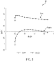
- Examples of active current and reactive current grid code requirements, which are to be met at the Pol 26, are shown in the chart 200 of Figure 2 .
- the grid requirement for active current output, the line for which is labelled 'I active ', at the Pol 26 is 1 pu active current at all voltage levels between 0.05 pu and 0.9 pu voltage.
- Figure 2 also illustrates that the grid requirements for reactive current output level at the Pol 26, labelled 'I reactive ', adopt a linear relationship between 0.8 pu reactive current at 0.2 pu voltage and 0.1 pu reactive current at 0.9 pu voltage, and between 0.8 pu and 0.85 pu reactive current at voltage levels below 0.2 pu voltage.
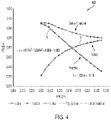
- FIG. 4 shows an example chart 400 illustrating typical active current (I active ) and reactive current (I reactive ) WTG injection profiles. Implementing these profiles at the WTGs 14 would result in compliant active and reactive current levels at the Pol 26 for a particular network. Also shown in Figure 4 is the total current (I active + I reactive ) supplied by the WTG at each voltage level, as well as trendlines, A and B, which will be discussed later. While Figure 4 only shows values upwards of 0.3 pu voltage, it will be appreciated that the injection profile may be calculated below this value.
- the WTG 14 is required to produce 1.2 pu reactive current for a measured voltage of 0.4 pu voltage.
- collector networks 17 between the Pol 26 and the WTGs 14s for different systems may vary highly depending upon the type of components incorporated into the network, the interconnection type between the grid 16 and the WPP 12, the quality of the components incorporated, the quality of the power incorporated, the age of the network, and the grid type.
- the impedance of the collector network 17 may vary, and this would result in different injection profiles. It is useful, therefore, to have a variable injection profile, as discussed below.
- K-factor relates to reactive current only, and specifies the relationship between reactive power and voltage.
- the K-factor is permanently programmed into the operating modes of the WTG controllers of the WPP, such that during a grid fault, the injected reactive power will be according to a predetermined profile will be used regardless of changes to the connecting network 17. Put another way, there is no adaptation of the injection profiles, let alone automatic adaptation.
- a control method according to the invention may be implemented, in which reactive and active current levels at the Pol 26 are continuously compliant with grid code requirements using feed-forward voltage control to alter injection profiles based upon measurements made relating to the state of the connector network.
- the control method of the invention results in automatic adaptation to changes in the collector network 17 of the network 10, as well as other changes that may affect the compliance of the WPP 12. Furthermore, the control method ensures immediate compliance, providing a further advantage over other control methods.
- Figures 5a and 5b show information flow diagrams 500, 550 between components of the power network 10 in normal voltage mode and under-voltage mode respectively. These diagrams demonstrate example flows of data or information according to an embodiment of the invention.
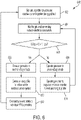
- Figure 6 shows an example control method 600 according to an embodiment of the invention.
- the control method 600 governs the operation of the power network 10 to ensure that compliance is achieved during a grid fault.
- the flow diagrams 500, 550 and method 600 are applicable to both reactive power and current injection and active power and current injection, and would be substantially the same for each of reactive and active power and current injection.
- the method would be implemented for both reactive and active current injection during a fault, to ensure complete compliance of the WPP with the requirements. However, for clarity, only active power and current will be discussed in relation to these Figures.
- 'normal voltage mode' is used throughout this specification to designate the mode and protocols according to which each WTG 14 is operated when voltage levels are considered to be within their 'normal operating band'. As discussed above, this band is typically between 0.9 pu voltage and 1.1 pu voltage at the terminal at the WTGs 14, although this band may be variable and measured from an alternative location, such as the Pol.
- the voltage level of the grid 16 is within this normal operating band, and both active current and reactive current set points are specified by the TSO 36, with the PPC 32 communicating active current reference values to the WTGs 14 via WTG controllers 15.
- the conventional information flow comprises the TSO 36 communicating at least one active power set point, P set , value to the PPC 32 and the PPC 32 formulating a plurality of active power reference, P ref, values based upon the P set value.
- the P set value communicated by the TSO 36 is the level of active current injection required by the grid 16, with each power plant connected to the grid 16 being expected to supply active current at that level.
- P ref values are set by the PPC 32 as levels to be met by each WTG 14.
- the output of active current by the WTGs 14 according to the P ref values specified by the PPC will result in the active power level at the Pol 26 being equal to P set .
- the P ref values Once the P ref values have been generated by the PPC 32, they are distributed, via the WTG controllers 15, to individual WTGs 14.
- the WTGs 14 then generate and output active power, P, at a level equal or similar to the P ref values.
- the P ref values distributed by the PPC 32 may be the same for each WTG 14 or different, depending upon the control method employed by the PPC 32, and the PPC 32 may use measurements to refine P ref values to bring the output of the WTGs 14 closer to P set .
- the parameters shown in Figure 5a are voltage level of the grid, U grid , and the impedance of the collector network, Z, and these may be monitored directly or indirectly.
- the voltage function indicated here as F n (U), is a predetermined voltage function whose output is an active current injection profile for use by WTGs 14 during a grid fault.
- the function requires a single input variable of voltage level at a known position in the connector network 17, such as the WTG terminal or point in the low voltage side 23 of the transformer 22.
- the function also includes a plurality of weights that are matched to an earlier state of the connector network 17 at a point in time, t n , such that input of the voltage level in the under-voltage mode results in active current output from the WPP 12 that translates to compliance with the grid code requirements at the Pol 26.
Landscapes
- Engineering & Computer Science (AREA)
- Power Engineering (AREA)
- Life Sciences & Earth Sciences (AREA)
- Sustainable Development (AREA)
- Sustainable Energy (AREA)
- Chemical & Material Sciences (AREA)
- Combustion & Propulsion (AREA)
- Mechanical Engineering (AREA)
- General Engineering & Computer Science (AREA)
- Supply And Distribution Of Alternating Current (AREA)
- Control Of Eletrric Generators (AREA)
Description
- The present disclosure relates to a method of controlling a renewable energy power plant, to a renewable energy power plant controller, and to a wind turbine power plant more generally.
- Newly commissioned renewable power plants, and more particularly wind power plants, are expected to be able to operate and adapt to a number of different circumstances when connected to a power network. A wind power plant (WPP) typically comprises a plurality of wind turbine generators and is also known as a wind park or a wind farm. The regulation and general operation of the power plant is controlled by a power plant control system or controller (PPC), which implements operational limits and requirements as set out by a Transmission System Operator (TSO) or in country-specific grid interconnection requirements or 'grid codes'. The TSO also communicates power delivery demands to the PPC, including active and/or reactive current delivery demands.
- Grid codes commonly include specific requirements for reactive and/or active current supply during a fault. These requirements ensure that the network is fully supported throughout the fault and that voltage level recovery is sustained by the active and/or reactive current supplied by the wind power plant or plants.
- While requirements used to be specified at each generating unit, the practice more recently, has been for grid code requirements for current supply levels to be specified at a Point of Interconnection (Pol) between the grid and the power plant. This allows for distributed current generation and flexibility in how the current is supplied to the grid by the power plant. However, it also often results in grid code requirements not being met during faults. The reason for this is to permit fast reaction to a fault from the grid, thus the wind turbine generators act as autonomous current sources that are de-coupled from the control of the PPC during the fault. This is despite the requirements being specified for the Pol.
- One approach to ensure that the requirements are met during a fault is to estimate, prior to installation of the power plant, the required injection profile for each wind turbine generator. One example of this is based on a linear weighting, or 'K-factor', as described in the German Grid Code and standard EN 50549. The K-factor is used as only reactive current control is specified, while there are no requirements for active current. However, any change in grid condition or to the WPP may result in non-compliance. Furthermore, new requirements for active current would not be able to be implemented by current systems using only a K-factor.
- Among further relevant prior art are
EP 2267306 A2 andWO 2015/086022 A1 . - It is an aim of the present invention to improve upon the prior art.
- According to an aspect of the present invention there is provided a method for controlling a renewable energy generator, the renewable energy generator being connected to a Point of Interconnection of an external power grid by a connecting network including a transformer. The connecting network has an associated impedance level. The method comprises: monitoring parameters of the connecting network and the voltage level at the Point of Interconnection, wherein the parameters comprise the impedance of the connecting network and a voltage level measured at a point in the connecting network between a low-voltage side of the transformer and the renewable energy generator; generating, during normal operating conditions, at least one current injection profile based upon the voltage level at the Point of Interconnection, the impedance of the connecting network and a predetermined injection profile, wherein normal operating conditions is when the voltage level of the external power grid is within a normal operating band; and operating the renewable energy generator, during a grid fault, to output current according to the generated current injection profile and the voltage level measured at the point in the connecting network between the low-voltage side of the transformer and the renewable energy generator, so as to achieve a current set point at the Point of Interconnection, wherein grid fault is when the voltage level of the external power grid is outside the normal operating band.
- Advantageously, generating current injection profiles during normal operation facilitates the generation of more accurate injection profiles, due to the parameters available for monitoring. The operation of the generator according to those profiles during a grid fault results in immediate compliance with grid code requirements. This means that the power plant that the generator forms part of is able to support grid recovery immediately, reducing the likelihood of disconnection or damage to the system.
- Is to be understood that some parameters should be monitored at a point being significantly different from the Point of Interconnection. Thus, the parameters should reflect properties of the connection network and not the Point of Interconnection, save for cases where there the properties are identical.
- Generating, during normal operating conditions at least one current injection profile may comprise calculating a voltage function.
- A voltage function beneficially ensures a straightforward calculation that can be made very quickly by a control system to achieve fast adoption of the correct output current level.
- The voltage function may comprise at least one weighting. The voltage function may require an input of the voltage measured at the point between the renewable energy generator and the low-voltage side of the transformer of the connecting network only.
- In requiring only a single input, here voltage level at a point in the connector network, arrival at an output current level requires minimal computing. The point between the renewable energy generator and the low voltage transformer of the connecting network may be a terminal of the renewable energy generator.
- The current injection profile may be an active current injection profile. The current injection profile may be a reactive current injection profile. The voltage function may be a first order polynomial, a second order polynomial, a third order polynomial, a fourth order polynomial, or a polynomial of a higher order.
- The predetermined injection profile upon which the at least one current injection profile may be an earlier iteration of the current injection profile.
- Iteratively updating an injection profile further reduces the computational power required to implement this method, permitting its use in existing power plants and with existing generators.
- The step of generating, during normal operating conditions, at least one current injection profile may be performed at intervals while normal operating conditions persist, such that the injection profile is updated iteratively.
- For example, the generation may be performed at intervals as requested by an external system, or according to a predetermined period, or when a change in a particular monitored parameter is identified. Usefully, generating updated injection profiles through a period of normal operation results in an up-to-date profile when required, such that the output of the generator is compliant at the Point of Interconnection.
- The parameters comprise a voltage level measured at a point in the connecting network between the low-voltage side of the transformer and the renewable energy generator. It is to be understood that the voltage level should be measured sufficiently remote from the Point of Interconnection such that the measurement reflects the voltage level at a point in the connection network and not at the Point of Interconnection.
- The current set point may be based on grid code requirements.
- The method may comprise updating a stored current injection profile once a new current injection profile has been generated.
- The method may comprise setting a default current injection profile. The default current injection profile may be the predetermined injection profile for the first iteration of the generating step.
- According to another aspect of the invention, there is provided a renewable energy power plant comprising a plurality of renewable energy generators and a control system for controlling the current output of the plurality of renewable energy generators, a connecting network including a transformer and connecting those renewable energy generators to a Point of Interconnection (Pol) with which the connecting network is connected to an external power grid, and measurement means configured to measure a voltage level at the Point of Interconnection and electrical parameters of the connecting network comprising the impedance of the connecting network and a voltage level at a point in the connecting network between a low-voltage side of the transformer and the renewable energy generators. The control system is configured to: generate, during normal operating conditions, at least one current injection profile based upon the measured voltage level at the Point of Interconnection, the impedance of the connecting network and a predetermined injection profile, wherein the normal operating conditions is when the voltage level of the external power gird is within a normal operating band; and operate the renewable energy generators, during a grid fault, to output power according to the generated current injection profile and the voltage level measured at the point in the connecting network between the low-voltage side of the transformer and the renewable energy generators, such that the current level injected by the renewable energy generators to the connecting network results in a current set point being met at the Point of Interconnection, wherein grid fault is when the voltage level of the external power grid is outside the normal operating band.
- According to another aspect of the invention, there is provided a computer program downloadable from a communication network and/or stored on a machine readable medium, comprising program code instructions which, when executed on a computer, cause the computer to implement a method as described above.
- One or more embodiments of the invention will now be described, by way of example only, with reference to the accompanying drawings, in which:
-
Figure 1 is a schematic view of a power network including a wind power plant and a main grid according to an embodiment of the invention; -
Figure 2 is a chart outlining grid code requirements for active current and reactive current as a function of voltage specified for the Point of Interconnection (Pol); -
Figure 3 is a chart outlining Pol active current and reactive current as a function of voltage in response to the injection profiles ofFigure 2 being implemented at each wind turbine generator; -
Figure 4 is a chart outlining required output of active current and reactive current for a given impedance between the wind turbine generator and the Pol as a function of voltage at the terminal of a wind turbine generator to replicate the profiles shown inFigure 2 at the Pol; -
Figures 5a and5b are information flow diagrams between elements of the power network for a normal voltage mode and an under-voltage mode respectively; and -
Figure 6 is a flow chart illustrating a process governing the operation of a power network according to an embodiment of the invention. -
Figure 1 illustrates a typical architecture in which a wind power plant (WPP) is connected to a main transmission grid as part of a wider power network. The example shown is representative only and the skilled reader will appreciate other specific architectures are possible, in relation to both wind power plants and power plants for other renewable energy sources. In addition, the skilled reader will appreciate that methods, systems and techniques also described below may be applicable to many different configurations of power network. Moreover, the components of the wind power plant and power network are conventional and as such would be familiar to the skilled reader. In particular, while a WPP is described herein as having a plurality of wind turbine generators, it will be appreciated that the WPP may also be considered to comprise STATCOM equipment, substation equipment, cables, plant controllers, and other componentry required to connect the WPP to a main grid. -
Figure 1 shows a power network 10 incorporating a wind power plant (WPP) 12 including a plurality of wind turbine generators 14 (WTGs), often more commonly called 'wind turbines'. Each of the plurality ofWTGs 14 converts wind energy into electrical energy, which is transferred from theWTGs 14 to a maintransmission power network 16 or main grid, as active current, for distribution. A connecting network 17 extends between theWPP 12 and themain grid 16. -
WTGs 14 generate both active current and reactive current. Themain grid 16 often has specific active and reactive current requirements with which theWPP 12 is required to comply, and the output of theWTGs 14 can be changed to match these requirements in real time. In particular, grid requirements specify current levels required to support voltage levels of themain grid 16 during a grid fault, and the output ofWTGs 14 can be manipulated to meet these. The method and system described herein according to embodiments of the invention act to ensure that the output of theWTGs 14, and hence theWPP 12, is sufficient to overcome impedances in the system 10 between thegrid 16 and theWTGs 14 and to supply a required and correct amount of current as necessary. The method and system implement feed-forward voltage control that may be applied to any renewable energy power plant or network, and that ensures that active and reactive current requirements are met immediately during a fault. The implementation of such feed-forward voltage control ensure that complex calculations are not required to be performed at any time to ensure compliance of theWPP 12. - Returning to
Figure 1 , each of theWTGs 14 of theWPP 12 is connected to a local grid (not shown) that links theWTGs 14. TheWPP 12 is, in turn, suitably connected to a collector bus 18 via afeeder line 20. The collector bus 18 may be at an intermediate voltage level that is suitable for relatively short distance power transmission, for example in the region of 10 kV to 36 kV. The collector bus 18 may also provide a point of common coupling (PCC) for a plurality of wind power plants, although, only asingle WPP 12 is shown here for simplicity. - The collector bus 18 is connected to a main step-up
transformer 22 by atransmission line 24. Themain transformer 22 is in turn connected to themain grid 16 at a Point of Interconnection (Pol) 26 by anothertransmission line 28. ThePol 26 is an interface between theWPP 12 and themain grid 16, such that the connecting network 17 extends between theWPP 12 and thePol 26, thereby connecting theWPP 12 to themain grid 16. It will be appreciated that more transformers may be included within the connecting network 17 as required. - While the collector bus 18 may be required to span distances up to around 100km, the
main grid 16 may be an international, national, or regional grid such as the National Grid of Great Britain, for example, and therefore may be required to span distances of up to around 250km or more. Accordingly, the voltage level of themain grid 16 may be much higher than the voltage level of the collector bus 18 for better transmission efficiency. - Hereinafter, it should be assumed that references to components being connected or connections between components comprise suitable feeder or transmission lines as described above unless it is otherwise indicated.
- A Power Plant Controller (PPC) 32 is connected to the power network 10 at a Point of Measurement (PoM) 34 and is also connected directly to the
WPP 12. The role of thePPC 32 is to act as a command and control interface between theWPP 12 and a grid operator or transmission system operator (TSO) 36. TheTSO 36 is responsible for indicating the needs and requirements of themain grid 16 to thePPC 32. ThePPC 32, in its role as command and control interface, interprets the power delivery demands requested of it by theTSO 36 and manages thewind turbines 14 in theWPP 12 in order to satisfy those requirements, whilst taking into account other operative factors such as grid faults and sudden changes in output or measured grid voltage. - The
PPC 32 is a suitable computer system for carrying out the controls and commands as described above and so incorporates at least a processing module 38, aconnectivity module 40, a memory module 42 and asensing module 44. - In order to monitor and regulate the output of the
WPP 12 and to interpret the power demands correctly, thePPC 32 is connected to thetransmission line 28 between themain transformer 22 and thePol 26 at thePoM 34. ThePPC 32 is equipped to measure a variety of parameters including a representative power output that will be supplied to themain grid 16 at thePol 26 by theWPP 12. As thePoM 34 is not at thePol 26, the measured parameters are only representative as losses in the lines between thePoM 34 andPol 26, and between thePoM 34 and thePPC 32, may have an effect on the measurements. Suitable compensation may take place to account for the losses to ensure that the measurements are accurate. - In addition, the
PPC 32 measures parameters of the power output such as a frequency and voltage, as well as reactive current exchange between theWPP 12 and themain grid 16 and the voltage level of themain grid 16. ThePPC 32 compares the measured parameters against specific grid requirements and communicates control commands to specific components of theWPP 12 accordingly. TheWPP 12 is capable of altering its reactive current output in reaction to commands received from thePPC 32. - The
PPC 32 communicates control commands to theturbines 14 in a suitable manner. It will be noted thatFigure 1 is a schematic view, so the way in which the control commands are transferred to theturbines 14 is not depicted explicitly. However, it will be appreciated that suitable cabling may be provided to interconnect thePPC 32 and theturbines 14. The interconnections may be direct or 'point to point' connections, or may be part of a local area network (LAN) operated under a suitable protocol (CAN-bus or Ethernet for example). Also, it should be appreciated that rather than using cabling, the control commands may be transmitted wirelessly over a suitable wireless network, for example operating under WFi™ or ZigBee™ standards (IEEE802.11 and 802.15.4 respectively). - The diagram of
Figure 1 should only be taken as a representation of a power network. Alternative configurations of power network and power plants are known and it is expected that other known components may be incorporated in addition to or as alternatives to the components shown and described inFigure 1 . Such changes would be within the capabilities of the skilled person. For example, substations or extra transformers would be expected to be incorporated in the wind power plant depending upon the number of turbines included in the plurality of wind turbines. - In some embodiments, the
PoM 34 may be positioned at a different position in the system such that the parameters measured by thePPC 32 are not representative of the actual values for those parameters at thePol 26 and the values may differ. In this case, a correction factor may be applied to the measurements to adjust for the different position of thePoM 34 relative to thePol 26. It therefore does not matter where thePoM 34 is located with regard to thePol 26, so long as there is a predetermined correction factor. Therefore, the measured voltage may be indicative of, or associated with, the voltage at the point of interconnection, even if the voltage is not measured directly at that location. - For the purposes of the present application, it is assumed that the
PoM 34 is at same location as thePol 26, and subsequent references to measurements will only be made with reference to thePol 26. It will be appreciated, as discussed above, that thePoM 34 may be positioned at a different position and the difference in magnitude of each measurement due to this different position may be accounted for with a correction factor without affecting the operation of the system. - As described above, the
WPP 12 must comply with a set of grid requirements specific to themain grid 16. In particular, the operation of thePPC 32 andWPP 12 in reaction to a grid fault is especially important. The reaction to a grid fault requires careful control of both voltage and power outputs to firstly fulfil grid requirements and secondly to support thegrid 16 to enable an efficient recovery to normal operating voltage levels. - As will be understood by the skilled person, a grid fault, or grid fault event, is generally defined as a period in which the voltage level of the
grid 16 or wider power network drops to a level outside the accepted and normal operational voltage bounds. During a grid fault in which grid voltage levels drop below predefined thresholds, theWPP 12 operates in an under-voltage mode, such as an under-voltage ride through (UVRT) mode, to avoid disconnection of theWPP 12 from thegrid 16 and to support thegrid 16 through the fault (under-voltage ride through is also known as low voltage ride through). In the under-voltage mode, theWPP 12 supports thegrid 16 during the fault by supplying reactive current to encourage a rise in voltage levels. TheWPP 12 is required to supply reactive current until the voltage levels have returned to levels that are within a normal operating voltage band. In many circumstances, this operating band is between voltage levels of 0.9 per-unit (pu) voltage and 1.1 pu voltage. - The
WPP 12 may alternatively experience a grid fault in which grid voltage levels rise above normal operational levels, and theWPP 12 may operate in an over-voltage mode, such as an over-voltage ride through (OVRT) mode, in these situations. Under-voltage situations are discussed throughout this specification, but it will be appreciated that the principles are equally applicable to over-voltage situations. - As would be understood by the skilled person, per-unit voltage is an expression of the voltage with respect to a base value which is used as a reference. Similarly, per-unit active current, or per-unit reactive current is an expression of the power/current with respect to a reference base value. Using a per-unit system allows for normalization of values across transformers and other components that may change the value by an order of magnitude.
- When operating in the under-voltage mode, the
WTGs 14 of theWPP 12 act autonomously and are controlled byWTG controllers 15 instead of being controlled by thePPC 32 as would ordinarily happen in normal voltage modes. TheWTGs 14 are controlled to output active and reactive current based on the voltage levels measured at a predetermined position. For example, the measurement may be made across the individual terminals of theWTGs 14 or at a point in the connecting network 17 on the low-voltage side 23 of thetransformer 22, where the low-voltage side 23 of thetransformer 22 extends between theWPP 12 and thetransformer 22. However, the grid requirements for active and reactive current are specified at thePol 26, and not forindividual WTGs 14. As the collector network 17 has an associated impedance, a difference exists between the measured active or reactive current output across the terminal of eachWTG 14 and the measured output at thePol 26. - Examples of active current and reactive current grid code requirements, which are to be met at the
Pol 26, are shown in thechart 200 ofFigure 2 . InFigure 2 , it can be seen that the grid requirement for active current output, the line for which is labelled 'Iactive', at thePol 26 is 1 pu active current at all voltage levels between 0.05 pu and 0.9 pu voltage.Figure 2 also illustrates that the grid requirements for reactive current output level at thePol 26, labelled 'Ireactive', adopt a linear relationship between 0.8 pu reactive current at 0.2 pu voltage and 0.1 pu reactive current at 0.9 pu voltage, and between 0.8 pu and 0.85 pu reactive current at voltage levels below 0.2 pu voltage. - It has already been discussed that collector networks 17 and, more generally, all componentry used in electrical systems, have an associated impedance. The consequence of this impedance is that active current or reactive current injected at one point in power network will not be replicated at another point in the power network, but will, in fact, be altered. The impedance of the system results in changes in active and reactive current levels at different points on the network. So, if an operator were to control a
WTG 14 to output active current and reactive current according to the grid code requirements ofFigure 2 , without consideration for the impedance of the system, the outputs would be very different elsewhere in the network 10. While the output at the WTG terminal would mirror the graph shown inFigure 2 , the collector network 17's impedance will result in very different active and reactive current profiles at thePol 26. Thechart 300 ofFigure 3 illustrates an example of this scenario. - In the
chart 300 ofFigure 3 , it can be seen that active current level achieved at thePol 26 is well above the required levels, varying substantially between 0.2 and 0.9 pu voltage. It can also be seen, that below 0.2 pu voltage, output levels of active current from theWTG 14 would result in non-compliance of theWPP 12 at thePol 26.Figure 3 also shows that reactive current at thePol 26 would be non-compliant at all voltage levels. - Therefore, to be compliant at the
Pol 26, WTG injection profiles during grid faults must be quite different.Figure 4 shows anexample chart 400 illustrating typical active current (Iactive) and reactive current (Ireactive) WTG injection profiles. Implementing these profiles at theWTGs 14 would result in compliant active and reactive current levels at thePol 26 for a particular network. Also shown inFigure 4 is the total current (Iactive + Ireactive) supplied by the WTG at each voltage level, as well as trendlines, A and B, which will be discussed later. WhileFigure 4 only shows values upwards of 0.3 pu voltage, it will be appreciated that the injection profile may be calculated below this value. - Using the profiles of
Figure 4 , in order to achieve compliance at thePol 26 by realising an active current output level of 1 pu active current at all voltages at thePol 26, theWTG 14 must produce a varying amount of active current that increases with increasing voltage. For example, for the particular network on which the values inFigure 4 are based, if the measured voltage is 0.4 pu voltage, the grid requirement active current level is 1 pu active current, and to achieve this level, the output active current from theWTG 14 must be 0.5 pu active current. - It should also be considered that at the same time as outputting 0.5 pu active current, the
WTG 14 is required to produce 1.2 pu reactive current for a measured voltage of 0.4 pu voltage. - Similarly, from
Figure 2 it is shown that, to achieve compliance of reactive current output level at thePol 26, a linear requirement exists between 0.8 pu reactive current at 0.2 pu voltage and 0.1 pu reactive current at 0.9 pu voltage. The corresponding WTG requirements for the particular network are shown inFigure 4 , including a corresponding linear injection profile that extends between approximately 1.3 pu and 0.3 pu reactive current for voltage levels between 0.3 pu and 0.95 pu voltage. For a measured voltage level of 0.4 pu voltage, the reactive current level required by the grid requirements is 0.6 pu reactive current, and, according toFigure 4 , theWTG 14 must supply 1.2 pu reactive current. - Compliance in terms of the grid requirement is achieved through a combination of reactive and active current injection. The reactive current injected by each
WTG 14 of theWPP 12 raises the voltage level at the terminal of thatWTG 14. - It will be appreciated that the injection profiles illustrated in
Figure 4 are for example only, and in reality, collector networks 17 between thePol 26 and the WTGs 14s for different systems may vary highly depending upon the type of components incorporated into the network, the interconnection type between thegrid 16 and theWPP 12, the quality of the components incorporated, the quality of the power incorporated, the age of the network, and the grid type. Thus, the impedance of the collector network 17 may vary, and this would result in different injection profiles. It is useful, therefore, to have a variable injection profile, as discussed below. - To achieve the correct levels at the
Pol 26 according to the grid code, conventional practice is to perform simulations of the operation of a WPP and collector network 17 prior to installation of that WPP and collector network 17, and to use the results of these simulations to specify a single K-factor parameter for the WPP. This K-factor relates to reactive current only, and specifies the relationship between reactive power and voltage. The K-factor is permanently programmed into the operating modes of the WTG controllers of the WPP, such that during a grid fault, the injected reactive power will be according to a predetermined profile will be used regardless of changes to the connecting network 17. Put another way, there is no adaptation of the injection profiles, let alone automatic adaptation. - In these conventional situations, if the WTG output levels calculated for meeting the grid requirement levels are incorrect then the output at the
Pol 26 will fall short of the levels specified by the grid requirements, and so theWPP 12 may not support thegrid 16 satisfactorily during the fault. This may result in a deeper voltage dip, or prolonged fault length and no counteraction of the fault. - To ensure that in under-voltage mode the
WTGs 14 operate to support thegrid 16 sufficiently, a control method according to the invention may be implemented, in which reactive and active current levels at thePol 26 are continuously compliant with grid code requirements using feed-forward voltage control to alter injection profiles based upon measurements made relating to the state of the connector network. The control method of the invention results in automatic adaptation to changes in the collector network 17 of the network 10, as well as other changes that may affect the compliance of theWPP 12. Furthermore, the control method ensures immediate compliance, providing a further advantage over other control methods. -
Figures 5a and5b show information flow diagrams 500, 550 between components of the power network 10 in normal voltage mode and under-voltage mode respectively. These diagrams demonstrate example flows of data or information according to an embodiment of the invention.Figure 6 shows anexample control method 600 according to an embodiment of the invention. Thecontrol method 600 governs the operation of the power network 10 to ensure that compliance is achieved during a grid fault. The flow diagrams 500, 550 andmethod 600 are applicable to both reactive power and current injection and active power and current injection, and would be substantially the same for each of reactive and active power and current injection. The method would be implemented for both reactive and active current injection during a fault, to ensure complete compliance of the WPP with the requirements. However, for clarity, only active power and current will be discussed in relation to these Figures. - Focussing initially on
Figure 5a , the communication of information between theTSO 36,PPC 32,WTG controller 15 andWTG 14 is shown for when theWPP 12 is being operated according to a normal voltage mode. It will also be appreciated that only communications between components that are pertinent to the invention are shown inFigures 5a and5b , so as not to impair the clarity of the Figures. - The term 'normal voltage mode' is used throughout this specification to designate the mode and protocols according to which each
WTG 14 is operated when voltage levels are considered to be within their 'normal operating band'. As discussed above, this band is typically between 0.9 pu voltage and 1.1 pu voltage at the terminal at theWTGs 14, although this band may be variable and measured from an alternative location, such as the Pol. WhenWTGs 14 are being operated according to the normal voltage mode, the voltage level of thegrid 16 is within this normal operating band, and both active current and reactive current set points are specified by theTSO 36, with thePPC 32 communicating active current reference values to theWTGs 14 viaWTG controllers 15. - In
Figure 5a , the conventional information flow relating to active power generation under normal voltage conditions is shown, as well as the new information flow relating to generation of active current references in the under-voltage ride-through mode. - The conventional information flow comprises the
TSO 36 communicating at least one active power set point, Pset, value to thePPC 32 and thePPC 32 formulating a plurality of active power reference, Pref, values based upon the Pset value. The Pset value communicated by theTSO 36 is the level of active current injection required by thegrid 16, with each power plant connected to thegrid 16 being expected to supply active current at that level. Pref values are set by thePPC 32 as levels to be met by eachWTG 14. The output of active current by theWTGs 14 according to the Pref values specified by the PPC will result in the active power level at thePol 26 being equal to Pset. Once the Pref values have been generated by thePPC 32, they are distributed, via theWTG controllers 15, toindividual WTGs 14. TheWTGs 14 then generate and output active power, P, at a level equal or similar to the Pref values. - The Pref values distributed by the
PPC 32 may be the same for eachWTG 14 or different, depending upon the control method employed by thePPC 32, and thePPC 32 may use measurements to refine Pref values to bring the output of theWTGs 14 closer to Pset. - As part of the conventional flow, it can also be seen in
Figure 5a that thePPC 32 also monitors parameters at thePoM 34, such as a measured active power output level, Pmeas, at thePoM 34. The measured active power output level is used as part of a closed loop to continually update to Pref values to ensure that Pmeas is in line with Pset. At least some of the parameters monitored by thePPC 32 are utilised in the new information flow to update a pre-programmed injection profile, in the form of a voltage function, thereby generating a new injection profile for active current injection during a grid fault. - The parameters shown in
Figure 5a are voltage level of the grid, Ugrid, and the impedance of the collector network, Z, and these may be monitored directly or indirectly. The voltage function, indicated here as Fn(U), is a predetermined voltage function whose output is an active current injection profile for use byWTGs 14 during a grid fault. The function requires a single input variable of voltage level at a known position in the connector network 17, such as the WTG terminal or point in thelow voltage side 23 of thetransformer 22. The function also includes a plurality of weights that are matched to an earlier state of the connector network 17 at a point in time, tn, such that input of the voltage level in the under-voltage mode results in active current output from theWPP 12 that translates to compliance with the grid code requirements at thePol 26. - The voltage function is pre-programmed within the
PPC 32 and is updated based upon the monitored parameters to result in a new injection profile, again in the form of a voltage function. This new voltage function is labelled Fn+1(U). The pre-programmed function, Fn(U), is either pre-programmed into thePPC 32 prior to theWPP 12 commencing operation, or pre-programmed in the sense that it is a previous iteration of the voltage function that has been previously used as Fn+1(U). - The pre-programmed function Fn(U) can be considered to be a voltage function that is matched to the connector network 17 at time tn, and would be sufficient to provide compliance if a grid fault were to occur at that point in time. The new voltage function Fn+1(U) is an update to Fn(U) for a later time tn+1, and is matched to the connector network 17 at that later time. The update applied to the pre-programmed function takes into account changes in the connector network 17 that may affect the compliance of the
WTGs 14 if controlled according to the earlier function. This method of operation therefore results in a feed-forward voltage control that adapts to changes in the connector network by iteratively updating a pre-programmed voltage function according to measured parameters. - Having generated an updated voltage function, the function is communicated by the
PPC 32 toindividual WTG controllers 15. TheWTG controllers 15 store the updated function, overwriting the previous stored iteration. - Although not shown in
Figure 5a , once an updated function Fn+1(U) is calculated, this is then also stored within thePPC 32 as Fn(U), so that further updates can be subsequently performed in later iterations of the method. - Both flows shown in the diagram 500 of
Figure 5a , i.e. the flow for outputting active power and the flow for generating injection profiles that will be used in response to a fault, are performed continuously or at pre-determined intervals, such that any alterations in the condition of thegrid 16 or the connecting network 17 are accounted for and will not result in non-compliance. By continuously updating the injection profiles, changes in the connecting network, such as replacing a transformed, removing components within the network for maintenance, or moving a connection point to a different substation, will be accounted for so that the injection of active current during a grid fault will be compliant. - Although only one voltage function is distributed to WTG controllers in the above discussion, it will be appreciated that it is also possible to distribute WTG-specific functions to individual WTG controllers to account for differences in the local grid to which the WTGs connect initially. This is particularly useful in widely distributed WPPs, so that impedance differences are accounted for across the entire collector network.
- Example functions are shown in
Figure 4 by trendlines A, B. Trendline A is the result of a function generated for the network to ensure compliance of active current requirements at thePol 26, and corresponds to a third-order polynomial having the equation:
- Similarly, trendline B is a linear function that corresponds to the compliance curve for reactive current. Trendline B is characterised by the equation:

- In these equations, y corresponds to active current output, z to reactive current output, while x is voltage level, each expressed as per-unit values.
- So, in generating a new function according to the method described herein, a
PPC 32 would update the weightings of the first equation to match any changes to the measured values of the monitored parameters. In some embodiments, there may be a direct relationship between the change of a particular value and the change in each of the weightings within the equation. In alternative embodiments, the change may be used to update a model, or in some embodiments, the weightings may be completely recalculated based upon a new value. - Moreover, several different monitored parameters fare employed to alter the weightings, and in examples out of the scope of the invention the weightings may be based on one parameter only, such as impedance value or angle of impedance, or in embodiments are based on a plurality of parameters. In some embodiments, a plurality of parameters may be used to calculate a further parameter on which the weightings are based. For example, if it is not possible to measure the impedance of the connecting network 17 directly, then a calculation of the impedance may be performed based on the active and reactive current at the
Pol 26 and the sum of the active and reactive current measured at a point close to theWTGs 14, for example on the low-voltage side of thetransformer 22. - In one embodiment, the weightings may initially be calculated using the following method.
- Initially, the
chart 200 shown inFigure 2 for both Iactive and/or Ireactive is generated as a vector, IPol. - It is then assumed that either the voltage on the Pol doesn't have an angle or that it does and the voltage level at the Pol, UPol, can be used as a reference.
- The voltage drop, UZ, should then be calculated across the impedance, Z, for the given current, IPol, using:

- A vector, UWTG, is calculated for the voltage at the WTG terminal based on summing Uz and UPol.
- An apparent power at the WTG terminals is calculated, SWTG, where SWTG, is the product of WTG terminal voltage vector and the conjugate of IPol. Shown another way:

- Assuming that the voltage at the WTG terminal, seen from the WTG, has an angle of zero, the Iactive and Ireactive values can be calculated as:


- The final steps requires plotting each of Iactive and Ireactive against UWTG and generating a curve for each, typically a 3rd order estimation for Iactive and a linear estimation for Ireactive, and outputting the weightings required for each of these curves. It will be appreciated that other estimations may be used.
- Following determination of these values, changes in the values may then be utilised to quickly update the previous iteration of the function to generate a new function.
- Turning now to
Figure 5b , the operation of theTSO 36,PPC 32,WTG controller 15 andWTG 14 during an under-voltage mode are shown. In this mode, theWTGs 14 of theWPP 12 act autonomously and are controlled byWTG controllers 15 instead of being controlled by thePPC 32 as happens in normal voltage mode. TheWTGs 14 are controlled by theirWTG controller 15 to output active and reactive current based on the voltage levels measured across their individual terminals, Uterminal, or based on voltage measurements at a point in the connecting network 17 on the low-voltage side 23 of thetransformer 22, Utrafo. - In response to the under-voltage mode, each
WTG controller 15 controls itsWTG 14 according to the injection profile function, here labelled F(U), that was generated by thePPC 32 during the normal voltage mode. Using the function, and the measured voltage level Uterminal or Utrafo, active current reference, Iactive_ref, values are generated by theWTG controller 15 for communicating to theWTG 14, which in turn outputs active current, Iactive, according to the Iactive_ref values. - Therefore, the
WTG 14 is operated according to a set injection profile throughout the fault and for as long as the under-voltage mode is active. The injection profile, an example of which has already been discussed in relation toFigure 4 , is dependent only upon the voltage level measured at the terminal of aWTG 14 ortransformer 22. Once the fault is cleared, under-voltage mode is terminated, and the system returns to its normal voltage mode, updating the injection profiles continues, and the Pref values are supplied by thePPC 32 again, as shown inFigure 5a . - The operation of the
WTGs 14 can be expressed as amethod 600, as shown inFigure 6 . Themethod 600 ofFigure 6 is only one method by which the above modes can be implemented, and the skilled person would readily understand that the operation of thePPC 32 to update an active or reactive current injection profile according to measured parameters in a normal voltage mode, and the implementation of those profiles during an under-voltage mode by aWTG controller 15 may be performed in many different ways. In some alternative embodiments, the order of the method steps ofFigure 6 may be switched or altered. - In the first step of the
method 600, a default profile is set 602 for active or reactive current injection. This step corresponds to the updating of the function/injection profile shown inFigure 5a . As discussed in relation to that figure, the default profile may be a pre-installation estimated profile, or the most recently generated injection profile. - In either case, once the default profile has been set 602, electrical parameters of the
grid 16 and connecting network are monitored 604. For example, the voltage of thegrid 16 and the impedance of the connecting network 17 may be monitored. - Having measured/monitored 604 the voltage level, a
check 606 is performed, in which it is determined if voltage levels have deviated from the normal operating bounds. If the voltage level is within the normal operating bounds, here given their conventional values of 0.9 pu and 1.1 pu, then theWPP 12, and more importantly theWTGs 14 are operated 608 in the normal voltage mode. - As discussed above, in the normal voltage mode, the
PPC 32, using the monitored parameters and the default profile previously set, generates 610 a new injection profile for active and/or reactive current injection. Once this new injection profile has been generated 610, it is communicated 612 to theindividual WTG controllers 15. It is likely that eachWTG controller 15 will receive an injection profile that is specific to it due to changes in impedance introduced by the local grid to which theWTGs 14 of theWPP 12 are connected. - Having communicated 612 the new profiles to the
individual WTG controllers 15, the default profile of thePPC 32 is updated, i.e. set 602, and themethod 600 begins again. - If, however, during the
voltage check step 606, it is determined that a voltage deviation has occurred, and as such a fault has occurred, then an under-voltage mode 614 is entered in which eachWTG 14 acts autonomously from thePPC 32. In this under-voltage mode, theWTGs 14 are operated 616 according to the most recently received injection profile. While the fault is continuing, themethod 600 returns to themonitoring step 604, and the parameters are monitored. The under-voltage mode is terminated only when the voltage returns to its ordinary limits. - In some embodiments, termination of the under-voltage mode may be dependent upon an alternative exit condition, other than voltage level.
- In some embodiments, alternative renewable energy generators or a hybrid power plant may be operated according to the methods described herein.
- Many modifications may be made to the above examples without departing from the scope of the present invention as defined in the accompanying claims.
Claims (12)
- A method for controlling a renewable energy generator (14), the renewable energy generator (14) being connected to a Point of Interconnection (26) of an external power grid (16) by a connecting network (17), wherein the connecting network (17) inlcudes a transformer (22), the method comprising:monitoring parameters of the connecting network (17) and the voltage level at the Point of Interconnection (26), wherein the parameters comprise the impedance (Z) of the connecting network (17) and a voltage level measured at a point in the connecting network (17) between a low-voltage side of the transformer (22) and the renewable energy generator (14);characterized bygenerating, during normal operating conditions, at least one current injection profile based upon the monitored voltage level at the Point of Interconnection (26), the impedance (Z) of the connecting network (17) and a predetermined injection profile, wherein normal operating conditions is when the voltage level of the external power grid (16) is within normal operating band; andoperating the renewable energy generator (14), during a grid fault, to output current according to the generated current injection profile and the voltage level measured at the point in the connecting network (17) between the low voltage side of the transformer (22) and the renewable energy generator, so as to achieve a current set point at the Point of Interconnection (26), wherein grid fault is when the voltage level of the external power grid (16) is outside the normal operating band.
- The method of Claim 1, wherein generating, during normal operating conditions at least one current injection profile comprises calculating a voltage function.
- The method of Claim 2, wherein the voltage function comprises at least one weighting and requires an input of voltage measured at the point between the renewable energy generator (14) and the low voltage side of the transformer (22) of the connecting network (17) only.
- The method of Claim 2 or Claim 3, wherein the current injection profile is an active current injection profile, and wherein the voltage function is a third order polynomial.
- The method of Claim 2 or Claim 3, wherein the current injection profile is a reactive current injection profile, and wherein the voltage function is a first order polynomial.
- The method of any preceding claim, wherein the predetermined injection profile upon which the at least one current injection profile is an earlier iteration of the current injection profile.
- The method of Claim 6, wherein the step of generating, during normal operating conditions, at least one current injection profile is performed at intervals while normal operating conditions persist, such that the injection profile is updated iteratively.
- The method of any preceding claim, wherein the current set point is based on grid code requirements.
- The method of any preceding claim, comprising updating a stored current injection profile once a new current injection profile has been generated.
- The method of any preceding claim, comprising setting a default current injection profile, the default current injection profile being the predetermined injection profile for the first iteration of the generating step.
- A renewable energy power plant (12) comprising a plurality of renewable energy generators (14) and a control system for controlling the current output of the plurality of renewable energy generators (14), a connecting network (17) including a transformer (22) and connecting those renewable energy generators (14) to a Point of Interconnection (26) with which the connecting network (17) is connected to an external power grid (16), and measurement means configured to measure a voltage level at the Point of Interconnection (26) and electrical parameters of the connecting network (17) comprising the impedance of the connecting network (17) and a voltage level measured at a point in the connecting network (17) between a low-voltage side of the transformer (22) and the renewable energy generators (14),
characterized in that the control system is configured to:generate, during normal operating conditions, at least one current injection profile based upon the measured voltage level at the Point of Interconnection (26), the impedance (Z) of the connecting network (17) and a predetermined injection profile, wherein normal operating conditions is when the voltage level of the external power grid (16) is within a normal operating band; andoperate the renewable energy generators (14), during a grid fault, to output power according to the generated injection profile and the voltage level measured at the point in the connecting network (17) between the low-voltage side of the transformer (22) and the renewable energy generators (14), such that the current level injected by the renewable energy generators (14) to the connecting network (17) results in a current set point being met at the Point of Interconnection (26), wherein grid fault is when the voltage level of the external power grid (16) is outside the normal operating band. - A computer program downloadable from a communication network and/or stored on a machine readable medium, comprising program code instructions which, when executed on a computer, cause the computer to implement a method in accordance with any of Claims 1 to 10.
Applications Claiming Priority (2)
| Application Number | Priority Date | Filing Date | Title |
|---|---|---|---|
| DKPA201770971 | 2017-12-21 | ||
| PCT/DK2018/050305 WO2019120400A1 (en) | 2017-12-21 | 2018-11-20 | Improvements relating to current injection in wind power plants |
Publications (2)
| Publication Number | Publication Date |
|---|---|
| EP3729592A1 EP3729592A1 (en) | 2020-10-28 |
| EP3729592B1 true EP3729592B1 (en) | 2022-09-07 |
Family
ID=64559419
Family Applications (1)
| Application Number | Title | Priority Date | Filing Date |
|---|---|---|---|
| EP18811438.3A Active EP3729592B1 (en) | 2017-12-21 | 2018-11-20 | Improvements relating to current injection in wind power plants |
Country Status (5)
| Country | Link |
|---|---|
| US (1) | US11855458B2 (en) |
| EP (1) | EP3729592B1 (en) |
| CN (1) | CN111448734B (en) |
| ES (1) | ES2927257T3 (en) |
| WO (1) | WO2019120400A1 (en) |
Families Citing this family (6)
| Publication number | Priority date | Publication date | Assignee | Title |
|---|---|---|---|---|
| DE102017112491A1 (en) * | 2017-06-07 | 2018-12-13 | Wobben Properties Gmbh | Method for operating a wind farm |
| WO2019120400A1 (en) | 2017-12-21 | 2019-06-27 | Vestas Wind Systems A/S | Improvements relating to current injection in wind power plants |
| EP3852214A1 (en) * | 2020-01-14 | 2021-07-21 | Wobben Properties GmbH | Method for controlling a wind energy system |
| CN113494428B (en) * | 2020-03-20 | 2022-11-22 | 新疆金风科技股份有限公司 | Fault detection method and device of wind generating set |
| CN117099282A (en) * | 2021-01-21 | 2023-11-21 | 维斯塔斯风力系统集团公司 | Method and system for enhanced active power control during frequency deviation |
| US12592583B2 (en) * | 2023-12-07 | 2026-03-31 | Caterpillar Inc. | Remote sensing and control at the point of common coupling in an electrical grid |
Family Cites Families (16)
| Publication number | Priority date | Publication date | Assignee | Title |
|---|---|---|---|---|
| EP0267306A1 (en) | 1986-11-10 | 1988-05-18 | Schoenelec-PFE GmbH | Testing device for electronic components packaged in tape |
| US8041465B2 (en) | 2008-10-09 | 2011-10-18 | General Electric Company | Voltage control at windfarms |
| US8655495B2 (en) * | 2009-06-24 | 2014-02-18 | Vestas Wind Systems A/S | Current control of a wind park |
| US10063059B2 (en) * | 2009-10-27 | 2018-08-28 | Vestas Wind Systems A/S | Wind power plant with optimal power output |
| CN101882798B (en) * | 2010-06-18 | 2012-10-17 | 深圳市禾望电气有限公司 | LVRT test control device |
| CN102709952B (en) * | 2011-03-28 | 2014-05-14 | 华锐风电科技(集团)股份有限公司 | Method and system for determining active power of each unit in electric network |
| US8610306B2 (en) | 2011-07-29 | 2013-12-17 | General Electric Company | Power plant control system and method for influencing high voltage characteristics |
| US9252596B2 (en) | 2011-11-28 | 2016-02-02 | General Electric Company | System and method for reactive power compensation in power networks |
| US9631608B2 (en) * | 2012-06-12 | 2017-04-25 | Vestas Wind Systems A/S | Wind-power-plant control upon low-voltage grid faults |
| MX2015009588A (en) * | 2013-02-26 | 2015-11-25 | Schweitzer Engineering Lab Inc | STATE TRAJECTORY PREDICTION IN AN ELECTRICAL POWER SUPPLY SYSTEM. |
| US10116138B2 (en) * | 2013-12-11 | 2018-10-30 | Vestas Wind Systems A/S | Wind power plant, and a method for controlling a reactive current injection in a wind power plant |
| US9831810B2 (en) | 2015-03-10 | 2017-11-28 | General Electric Company | System and method for improved reactive power speed-of-response for a wind farm |
| CN106712088B (en) * | 2017-01-17 | 2020-01-07 | 燕山大学 | Low-voltage microgrid inverter control system based on virtual impedance and virtual power |
| CN106786560B (en) * | 2017-02-14 | 2021-04-30 | 中国电力科学研究院 | Method and device for automatically extracting stability characteristics of power system |
| CN107359617B (en) | 2017-08-08 | 2023-09-26 | 国网江苏省电力公司盐城供电公司 | An active distribution source-grid-load coordination control system including a microgrid group |
| WO2019120400A1 (en) | 2017-12-21 | 2019-06-27 | Vestas Wind Systems A/S | Improvements relating to current injection in wind power plants |
-
2018
- 2018-11-20 WO PCT/DK2018/050305 patent/WO2019120400A1/en not_active Ceased
- 2018-11-20 CN CN201880078426.5A patent/CN111448734B/en active Active
- 2018-11-20 ES ES18811438T patent/ES2927257T3/en active Active
- 2018-11-20 EP EP18811438.3A patent/EP3729592B1/en active Active
- 2018-11-20 US US16/957,080 patent/US11855458B2/en active Active
Also Published As
| Publication number | Publication date |
|---|---|
| WO2019120400A1 (en) | 2019-06-27 |
| EP3729592A1 (en) | 2020-10-28 |
| US20200350765A1 (en) | 2020-11-05 |
| ES2927257T3 (en) | 2022-11-03 |
| CN111448734B (en) | 2023-05-26 |
| CN111448734A (en) | 2020-07-24 |
| US11855458B2 (en) | 2023-12-26 |
Similar Documents
| Publication | Publication Date | Title |
|---|---|---|
| US11855458B2 (en) | Current injection in wind power plants | |
| EP4064501B1 (en) | Improvements relating to voltage control in renewable power plants | |
| EP2236820B1 (en) | Voltage control method and system for a power generation plant and wind farm | |
| US8838284B2 (en) | Devices and methods for decentralized Volt/VAR control | |
| CN108370157B (en) | Method of controlling power distribution | |
| US8965588B2 (en) | Devices and methods for decentralized voltage control | |
| EP3669433B1 (en) | Improvements relating to reactive power control in wind power plants | |
| EP2175540B1 (en) | Voltage control at windfarms | |
| US20130030579A1 (en) | Devices and methods for decentralized power loss reduction control | |
| CN114747111B (en) | Active power control in renewable power stations for grid stability | |
| EP3526874A1 (en) | Improvements relating to reactive power control in wind power plants | |
| EP3682519B1 (en) | Improvements relating to voltage control in wind power plants | |
| US12113363B2 (en) | Control of a renewable energy power plant to resume normal operation following a fault | |
| EP3179594B1 (en) | Dynamic control method of power injected into the power grid by distributed generators | |
| Dragosavac et al. | Practical implementation of coordinated QV control in a multi-machine power plant | |
| EP3436692B1 (en) | Improvements relating to the interconnection of multiple renewable energy power plants | |
| CN114070201A (en) | Distributed photovoltaic monitoring control system | |
| WO2025119436A1 (en) | Methods and systems for improving control of a renewable energy power plant |
Legal Events
| Date | Code | Title | Description |
|---|---|---|---|
| STAA | Information on the status of an ep patent application or granted ep patent |
Free format text: STATUS: UNKNOWN |
|
| STAA | Information on the status of an ep patent application or granted ep patent |
Free format text: STATUS: THE INTERNATIONAL PUBLICATION HAS BEEN MADE |
|
| PUAI | Public reference made under article 153(3) epc to a published international application that has entered the european phase |
Free format text: ORIGINAL CODE: 0009012 |
|
| STAA | Information on the status of an ep patent application or granted ep patent |
Free format text: STATUS: REQUEST FOR EXAMINATION WAS MADE |
|
| 17P | Request for examination filed |
Effective date: 20200624 |
|
| AK | Designated contracting states |
Kind code of ref document: A1 Designated state(s): AL AT BE BG CH CY CZ DE DK EE ES FI FR GB GR HR HU IE IS IT LI LT LU LV MC MK MT NL NO PL PT RO RS SE SI SK SM TR |
|
| AX | Request for extension of the european patent |
Extension state: BA ME |
|
| DAV | Request for validation of the european patent (deleted) | ||
| DAX | Request for extension of the european patent (deleted) | ||
| STAA | Information on the status of an ep patent application or granted ep patent |
Free format text: STATUS: EXAMINATION IS IN PROGRESS |
|
| 17Q | First examination report despatched |
Effective date: 20210722 |
|
| GRAP | Despatch of communication of intention to grant a patent |
Free format text: ORIGINAL CODE: EPIDOSNIGR1 |
|
| STAA | Information on the status of an ep patent application or granted ep patent |
Free format text: STATUS: GRANT OF PATENT IS INTENDED |
|
| RIC1 | Information provided on ipc code assigned before grant |
Ipc: F03D 7/02 20060101ALN20220330BHEP Ipc: H02J 3/50 20060101ALN20220330BHEP Ipc: H02J 3/38 20060101ALI20220330BHEP Ipc: H02J 3/00 20060101ALI20220330BHEP Ipc: H02J 3/16 20060101AFI20220330BHEP |
|
| RIC1 | Information provided on ipc code assigned before grant |
Ipc: F03D 7/02 20060101ALN20220404BHEP Ipc: H02J 3/50 20060101ALN20220404BHEP Ipc: H02J 3/38 20060101ALI20220404BHEP Ipc: H02J 3/00 20060101ALI20220404BHEP Ipc: H02J 3/16 20060101AFI20220404BHEP |
|
| INTG | Intention to grant announced |
Effective date: 20220422 |
|
| GRAS | Grant fee paid |
Free format text: ORIGINAL CODE: EPIDOSNIGR3 |
|
| GRAA | (expected) grant |
Free format text: ORIGINAL CODE: 0009210 |
|
| STAA | Information on the status of an ep patent application or granted ep patent |
Free format text: STATUS: THE PATENT HAS BEEN GRANTED |
|
| AK | Designated contracting states |
Kind code of ref document: B1 Designated state(s): AL AT BE BG CH CY CZ DE DK EE ES FI FR GB GR HR HU IE IS IT LI LT LU LV MC MK MT NL NO PL PT RO RS SE SI SK SM TR |
|
| REG | Reference to a national code |
Ref country code: GB Ref legal event code: FG4D |
|
| REG | Reference to a national code |
Ref country code: CH Ref legal event code: EP Ref country code: AT Ref legal event code: REF Ref document number: 1517860 Country of ref document: AT Kind code of ref document: T Effective date: 20220915 |
|
| REG | Reference to a national code |
Ref country code: DE Ref legal event code: R096 Ref document number: 602018040428 Country of ref document: DE |
|
| REG | Reference to a national code |
Ref country code: IE Ref legal event code: FG4D |
|
| REG | Reference to a national code |
Ref country code: ES Ref legal event code: FG2A Ref document number: 2927257 Country of ref document: ES Kind code of ref document: T3 Effective date: 20221103 |
|
| REG | Reference to a national code |
Ref country code: LT Ref legal event code: MG9D |
|
| REG | Reference to a national code |
Ref country code: NL Ref legal event code: MP Effective date: 20220907 |
|
| PG25 | Lapsed in a contracting state [announced via postgrant information from national office to epo] |
Ref country code: SE Free format text: LAPSE BECAUSE OF FAILURE TO SUBMIT A TRANSLATION OF THE DESCRIPTION OR TO PAY THE FEE WITHIN THE PRESCRIBED TIME-LIMIT Effective date: 20220907 Ref country code: RS Free format text: LAPSE BECAUSE OF FAILURE TO SUBMIT A TRANSLATION OF THE DESCRIPTION OR TO PAY THE FEE WITHIN THE PRESCRIBED TIME-LIMIT Effective date: 20220907 Ref country code: NO Free format text: LAPSE BECAUSE OF FAILURE TO SUBMIT A TRANSLATION OF THE DESCRIPTION OR TO PAY THE FEE WITHIN THE PRESCRIBED TIME-LIMIT Effective date: 20221207 Ref country code: LV Free format text: LAPSE BECAUSE OF FAILURE TO SUBMIT A TRANSLATION OF THE DESCRIPTION OR TO PAY THE FEE WITHIN THE PRESCRIBED TIME-LIMIT Effective date: 20220907 Ref country code: LT Free format text: LAPSE BECAUSE OF FAILURE TO SUBMIT A TRANSLATION OF THE DESCRIPTION OR TO PAY THE FEE WITHIN THE PRESCRIBED TIME-LIMIT Effective date: 20220907 Ref country code: FI Free format text: LAPSE BECAUSE OF FAILURE TO SUBMIT A TRANSLATION OF THE DESCRIPTION OR TO PAY THE FEE WITHIN THE PRESCRIBED TIME-LIMIT Effective date: 20220907 |
|
| REG | Reference to a national code |
Ref country code: AT Ref legal event code: MK05 Ref document number: 1517860 Country of ref document: AT Kind code of ref document: T Effective date: 20220907 |
|
| PG25 | Lapsed in a contracting state [announced via postgrant information from national office to epo] |
Ref country code: HR Free format text: LAPSE BECAUSE OF FAILURE TO SUBMIT A TRANSLATION OF THE DESCRIPTION OR TO PAY THE FEE WITHIN THE PRESCRIBED TIME-LIMIT Effective date: 20220907 Ref country code: GR Free format text: LAPSE BECAUSE OF FAILURE TO SUBMIT A TRANSLATION OF THE DESCRIPTION OR TO PAY THE FEE WITHIN THE PRESCRIBED TIME-LIMIT Effective date: 20221208 |
|
| PG25 | Lapsed in a contracting state [announced via postgrant information from national office to epo] |
Ref country code: SM Free format text: LAPSE BECAUSE OF FAILURE TO SUBMIT A TRANSLATION OF THE DESCRIPTION OR TO PAY THE FEE WITHIN THE PRESCRIBED TIME-LIMIT Effective date: 20220907 Ref country code: RO Free format text: LAPSE BECAUSE OF FAILURE TO SUBMIT A TRANSLATION OF THE DESCRIPTION OR TO PAY THE FEE WITHIN THE PRESCRIBED TIME-LIMIT Effective date: 20220907 Ref country code: PT Free format text: LAPSE BECAUSE OF FAILURE TO SUBMIT A TRANSLATION OF THE DESCRIPTION OR TO PAY THE FEE WITHIN THE PRESCRIBED TIME-LIMIT Effective date: 20230109 Ref country code: CZ Free format text: LAPSE BECAUSE OF FAILURE TO SUBMIT A TRANSLATION OF THE DESCRIPTION OR TO PAY THE FEE WITHIN THE PRESCRIBED TIME-LIMIT Effective date: 20220907 Ref country code: AT Free format text: LAPSE BECAUSE OF FAILURE TO SUBMIT A TRANSLATION OF THE DESCRIPTION OR TO PAY THE FEE WITHIN THE PRESCRIBED TIME-LIMIT Effective date: 20220907 |
|
| PG25 | Lapsed in a contracting state [announced via postgrant information from national office to epo] |
Ref country code: SK Free format text: LAPSE BECAUSE OF FAILURE TO SUBMIT A TRANSLATION OF THE DESCRIPTION OR TO PAY THE FEE WITHIN THE PRESCRIBED TIME-LIMIT Effective date: 20220907 Ref country code: PL Free format text: LAPSE BECAUSE OF FAILURE TO SUBMIT A TRANSLATION OF THE DESCRIPTION OR TO PAY THE FEE WITHIN THE PRESCRIBED TIME-LIMIT Effective date: 20220907 Ref country code: IS Free format text: LAPSE BECAUSE OF FAILURE TO SUBMIT A TRANSLATION OF THE DESCRIPTION OR TO PAY THE FEE WITHIN THE PRESCRIBED TIME-LIMIT Effective date: 20230107 Ref country code: EE Free format text: LAPSE BECAUSE OF FAILURE TO SUBMIT A TRANSLATION OF THE DESCRIPTION OR TO PAY THE FEE WITHIN THE PRESCRIBED TIME-LIMIT Effective date: 20220907 |
|
| REG | Reference to a national code |
Ref country code: DE Ref legal event code: R097 Ref document number: 602018040428 Country of ref document: DE |
|
| P01 | Opt-out of the competence of the unified patent court (upc) registered |
Effective date: 20230521 |
|
| PG25 | Lapsed in a contracting state [announced via postgrant information from national office to epo] |
Ref country code: NL Free format text: LAPSE BECAUSE OF FAILURE TO SUBMIT A TRANSLATION OF THE DESCRIPTION OR TO PAY THE FEE WITHIN THE PRESCRIBED TIME-LIMIT Effective date: 20220907 Ref country code: MC Free format text: LAPSE BECAUSE OF FAILURE TO SUBMIT A TRANSLATION OF THE DESCRIPTION OR TO PAY THE FEE WITHIN THE PRESCRIBED TIME-LIMIT Effective date: 20220907 Ref country code: AL Free format text: LAPSE BECAUSE OF FAILURE TO SUBMIT A TRANSLATION OF THE DESCRIPTION OR TO PAY THE FEE WITHIN THE PRESCRIBED TIME-LIMIT Effective date: 20220907 |
|
| REG | Reference to a national code |
Ref country code: CH Ref legal event code: PL |
|
| PLBE | No opposition filed within time limit |
Free format text: ORIGINAL CODE: 0009261 |
|
| STAA | Information on the status of an ep patent application or granted ep patent |
Free format text: STATUS: NO OPPOSITION FILED WITHIN TIME LIMIT |
|
| REG | Reference to a national code |
Ref country code: BE Ref legal event code: MM Effective date: 20221130 |
|
| PG25 | Lapsed in a contracting state [announced via postgrant information from national office to epo] |
Ref country code: LI Free format text: LAPSE BECAUSE OF NON-PAYMENT OF DUE FEES Effective date: 20221130 Ref country code: DK Free format text: LAPSE BECAUSE OF FAILURE TO SUBMIT A TRANSLATION OF THE DESCRIPTION OR TO PAY THE FEE WITHIN THE PRESCRIBED TIME-LIMIT Effective date: 20220907 Ref country code: CH Free format text: LAPSE BECAUSE OF NON-PAYMENT OF DUE FEES Effective date: 20221130 |
|
| 26N | No opposition filed |
Effective date: 20230608 |
|
| PG25 | Lapsed in a contracting state [announced via postgrant information from national office to epo] |
Ref country code: SI Free format text: LAPSE BECAUSE OF FAILURE TO SUBMIT A TRANSLATION OF THE DESCRIPTION OR TO PAY THE FEE WITHIN THE PRESCRIBED TIME-LIMIT Effective date: 20220907 Ref country code: LU Free format text: LAPSE BECAUSE OF NON-PAYMENT OF DUE FEES Effective date: 20221120 |
|
| PG25 | Lapsed in a contracting state [announced via postgrant information from national office to epo] |
Ref country code: IE Free format text: LAPSE BECAUSE OF NON-PAYMENT OF DUE FEES Effective date: 20221120 |
|
| PG25 | Lapsed in a contracting state [announced via postgrant information from national office to epo] |
Ref country code: BE Free format text: LAPSE BECAUSE OF NON-PAYMENT OF DUE FEES Effective date: 20221130 |
|
| PG25 | Lapsed in a contracting state [announced via postgrant information from national office to epo] |
Ref country code: CY Free format text: LAPSE BECAUSE OF FAILURE TO SUBMIT A TRANSLATION OF THE DESCRIPTION OR TO PAY THE FEE WITHIN THE PRESCRIBED TIME-LIMIT Effective date: 20220907 |
|
| PG25 | Lapsed in a contracting state [announced via postgrant information from national office to epo] |
Ref country code: MK Free format text: LAPSE BECAUSE OF FAILURE TO SUBMIT A TRANSLATION OF THE DESCRIPTION OR TO PAY THE FEE WITHIN THE PRESCRIBED TIME-LIMIT Effective date: 20220907 Ref country code: IT Free format text: LAPSE BECAUSE OF FAILURE TO SUBMIT A TRANSLATION OF THE DESCRIPTION OR TO PAY THE FEE WITHIN THE PRESCRIBED TIME-LIMIT Effective date: 20220907 Ref country code: HU Free format text: LAPSE BECAUSE OF FAILURE TO SUBMIT A TRANSLATION OF THE DESCRIPTION OR TO PAY THE FEE WITHIN THE PRESCRIBED TIME-LIMIT; INVALID AB INITIO Effective date: 20181120 |
|
| PG25 | Lapsed in a contracting state [announced via postgrant information from national office to epo] |
Ref country code: BG Free format text: LAPSE BECAUSE OF FAILURE TO SUBMIT A TRANSLATION OF THE DESCRIPTION OR TO PAY THE FEE WITHIN THE PRESCRIBED TIME-LIMIT Effective date: 20220907 |
|
| PG25 | Lapsed in a contracting state [announced via postgrant information from national office to epo] |
Ref country code: MT Free format text: LAPSE BECAUSE OF FAILURE TO SUBMIT A TRANSLATION OF THE DESCRIPTION OR TO PAY THE FEE WITHIN THE PRESCRIBED TIME-LIMIT Effective date: 20220907 |
|
| PG25 | Lapsed in a contracting state [announced via postgrant information from national office to epo] |
Ref country code: TR Free format text: LAPSE BECAUSE OF FAILURE TO SUBMIT A TRANSLATION OF THE DESCRIPTION OR TO PAY THE FEE WITHIN THE PRESCRIBED TIME-LIMIT Effective date: 20220907 |
|
| PGFP | Annual fee paid to national office [announced via postgrant information from national office to epo] |
Ref country code: DE Payment date: 20251126 Year of fee payment: 8 |
|
| PGFP | Annual fee paid to national office [announced via postgrant information from national office to epo] |
Ref country code: GB Payment date: 20251125 Year of fee payment: 8 |
|
| PGFP | Annual fee paid to national office [announced via postgrant information from national office to epo] |
Ref country code: FR Payment date: 20251124 Year of fee payment: 8 |
|
| PGFP | Annual fee paid to national office [announced via postgrant information from national office to epo] |
Ref country code: ES Payment date: 20251209 Year of fee payment: 8 |