EP3728808B1 - Sealing gasket, for sealing the connection between an exhaust manifold and a turbine - Google Patents
Sealing gasket, for sealing the connection between an exhaust manifold and a turbine Download PDFInfo
- Publication number
- EP3728808B1 EP3728808B1 EP17849812.7A EP17849812A EP3728808B1 EP 3728808 B1 EP3728808 B1 EP 3728808B1 EP 17849812 A EP17849812 A EP 17849812A EP 3728808 B1 EP3728808 B1 EP 3728808B1
- Authority
- EP
- European Patent Office
- Prior art keywords
- sealing
- gasket
- sealing portion
- turbine
- previous
- Prior art date
- Legal status (The legal status is an assumption and is not a legal conclusion. Google has not performed a legal analysis and makes no representation as to the accuracy of the status listed.)
- Active
Links
Images


Classifications
-
- F—MECHANICAL ENGINEERING; LIGHTING; HEATING; WEAPONS; BLASTING
- F01—MACHINES OR ENGINES IN GENERAL; ENGINE PLANTS IN GENERAL; STEAM ENGINES
- F01N—GAS-FLOW SILENCERS OR EXHAUST APPARATUS FOR MACHINES OR ENGINES IN GENERAL; GAS-FLOW SILENCERS OR EXHAUST APPARATUS FOR INTERNAL-COMBUSTION ENGINES
- F01N13/00—Exhaust or silencing apparatus characterised by constructional features
- F01N13/08—Other arrangements or adaptations of exhaust conduits
- F01N13/10—Other arrangements or adaptations of exhaust conduits of exhaust manifolds
-
- F—MECHANICAL ENGINEERING; LIGHTING; HEATING; WEAPONS; BLASTING
- F01—MACHINES OR ENGINES IN GENERAL; ENGINE PLANTS IN GENERAL; STEAM ENGINES
- F01N—GAS-FLOW SILENCERS OR EXHAUST APPARATUS FOR MACHINES OR ENGINES IN GENERAL; GAS-FLOW SILENCERS OR EXHAUST APPARATUS FOR INTERNAL-COMBUSTION ENGINES
- F01N13/00—Exhaust or silencing apparatus characterised by constructional features
- F01N13/18—Construction facilitating manufacture, assembly, or disassembly
- F01N13/1805—Fixing exhaust manifolds, exhaust pipes or pipe sections to each other, to engine or to vehicle body
- F01N13/1827—Sealings specially adapted for exhaust systems
-
- F—MECHANICAL ENGINEERING; LIGHTING; HEATING; WEAPONS; BLASTING
- F02—COMBUSTION ENGINES; HOT-GAS OR COMBUSTION-PRODUCT ENGINE PLANTS
- F02B—INTERNAL-COMBUSTION PISTON ENGINES; COMBUSTION ENGINES IN GENERAL
- F02B37/00—Engines characterised by provision of pumps driven at least for part of the time by exhaust
-
- F—MECHANICAL ENGINEERING; LIGHTING; HEATING; WEAPONS; BLASTING
- F16—ENGINEERING ELEMENTS AND UNITS; GENERAL MEASURES FOR PRODUCING AND MAINTAINING EFFECTIVE FUNCTIONING OF MACHINES OR INSTALLATIONS; THERMAL INSULATION IN GENERAL
- F16J—PISTONS; CYLINDERS; SEALINGS
- F16J15/00—Sealings
- F16J15/02—Sealings between relatively-stationary surfaces
- F16J15/06—Sealings between relatively-stationary surfaces with solid packing compressed between sealing surfaces
- F16J15/08—Sealings between relatively-stationary surfaces with solid packing compressed between sealing surfaces with exclusively metal packing
- F16J15/0818—Flat gaskets
-
- F—MECHANICAL ENGINEERING; LIGHTING; HEATING; WEAPONS; BLASTING
- F02—COMBUSTION ENGINES; HOT-GAS OR COMBUSTION-PRODUCT ENGINE PLANTS
- F02B—INTERNAL-COMBUSTION PISTON ENGINES; COMBUSTION ENGINES IN GENERAL
- F02B37/00—Engines characterised by provision of pumps driven at least for part of the time by exhaust
- F02B37/02—Gas passages between engine outlet and pump drive, e.g. reservoirs
- F02B37/025—Multiple scrolls or multiple gas passages guiding the gas to the pump drive
-
- Y—GENERAL TAGGING OF NEW TECHNOLOGICAL DEVELOPMENTS; GENERAL TAGGING OF CROSS-SECTIONAL TECHNOLOGIES SPANNING OVER SEVERAL SECTIONS OF THE IPC; TECHNICAL SUBJECTS COVERED BY FORMER USPC CROSS-REFERENCE ART COLLECTIONS [XRACs] AND DIGESTS
- Y02—TECHNOLOGIES OR APPLICATIONS FOR MITIGATION OR ADAPTATION AGAINST CLIMATE CHANGE
- Y02T—CLIMATE CHANGE MITIGATION TECHNOLOGIES RELATED TO TRANSPORTATION
- Y02T10/00—Road transport of goods or passengers
- Y02T10/10—Internal combustion engine [ICE] based vehicles
- Y02T10/12—Improving ICE efficiencies
Definitions
- the present invention concerns a sealing gasket, for sealing the connection between an exhaust manifold and a Turbine.
- turbochargers are commonly used with Diesel cycle internal combustion engines.
- a turbocharger is a turbine-driven device that increases the efficiency and the power of an internal combustion engine by forcing extra air into the combustion chamber.
- a turbocharger is powered by a turbine driven by the hot exhaust gas of the engine.
- the turbine is a fixed geometry turbine that includes a flange provided with a dividing wall to separate the flow of exhaust gases in two flows.
- a flange provided with a dividing wall to separate the flow of exhaust gases in two flows.
- exhaust gases coming from the first three cylinders are separated from exhaust gases coming from the three other cylinders.
- a comparable flange is provided on the exhaust manifold. The separation of the exhaust gases in two separate flows helps reducing fuel consumption.
- gasket which is often referred to as a sealing gasket.
- This gasket includes two flow passage openings separated by a dividing wall.
- exhaust manifold and turbocharger dividing walls are subjected to high temperatures, in particular when a stabilized phase is reached, i.e. after long full load running.
- the hottest part of exhaust manifold and turbocharger are dividing walls as they are in contact with both hot gas flows circulating through exhaust manifold and turbocharger openings and as it is not in contact with ambient air.
- the thermal expansion of the dividing walls is then greater than for the rest of flanges, which causes contact pressure between dividing walls. This contact pressure reduces the contact pressure of the gasket on flanges, which may cause leakage issues.
- the invention intends to remedy these drawbacks by proposing a new gasket design, with which there is no risk of gas communication at the interface between the manifold and the turbine and with which there is less risk of leakages due to the thermal expansion of dividing walls.
- the invention concerns a sealing gasket, for sealing a connection between an exhaust manifold and a turbine of a vehicle, according to claim 1.
- EP 2 818 661 discloses an example of a sealing gasket between an exhaust manifold and a turbine.
- the sealing gasket includes a sealing portion extending around the two openings of the gasket.
- This sealing portion includes a seal ring housed in a ringshaped groove milled into the sealing gasket.
- the problem of this gasket is that it does not efficiently prevent gas communication at the interface between the turbine and the manifold.
- CN 20 30 67776 discloses another example of a sealing gasket, which is mounted between a turbo-supercharger and an exhaust manifold of a diesel engine.
- the gasket is provided with two flow passage openings and with two sealing ribs extending each around a respective opening of the gasket. The problem of this gasket is that it does not efficiently prevent gas leakages.
- the first sealing portion extending around the two openings enables avoiding as far as possible the gas leakages due to the thermal deformation of exhaust manifold and turbocharger flanges and the second sealing portion enables avoiding as far as possible the two flows of exhaust gas to communicate at the interface between the turbine and the manifold.
- the sealing functions of the gasket are enhanced in comparison with prior art sealing gaskets.
- the first and the second sealing portion are designed to compensate different deformation.
- the invention also concerns an internal combustion engine comprising an exhaust manifold, a turbine, and a sealing gasket as previously defined, sealing the connection between the turbine and the manifold.
- the invention also concerns a vehicle, such as a truck or a tractor truck, comprising an internal combustion engine as defined above.
- Figure 1 represents, in side view, a vehicle which is, in the example, a tractor truck 1.
- the vehicle may be different from a tractor truck.
- the vehicle may be a light, medium or heavy-duty vehicle, a utility vehicle, an autonomous vehicle, etc.
- the tractor truck 1 includes an internal combustion engine comprising an engine block (not represented) including a plurality of combustion cylinders, typically six cylinders.
- the engine further includes an exhaust gas manifold 4, represented on figure 3 , which collects the gas exhausting from the combustion chambers of the engine cylinders.
- the exhaust gas manifold 4 includes six inlets 4.1, 4.2, 4.3, 4.4, 4.5 and 4.6 to be respectively connected to the combustion chambers of the engine. Exhaust gases coming from the first three cylinders, i.e. flowing in the inlets 4.1 to 4.3, are separated from exhaust gases coming from the three other cylinders, i.e. flowing in the inlets 4.4 to 4.6.
- the manifold 4 includes two gas flow channels 42 and 44 that open on a connecting flange 40 of the manifold 4. Both gas flow channels 42 and 44 are separated by a dividing wall 45 of the manifold 4. The dividing wall 45 extends up to the connecting flange 40.
- the engine also includes a turbocharger 6 (cf. figure 2 ) comprising a compressor part 6.1 and turbine part 6.2 that can be, for instance, a fixed geometry turbine (FGT).
- Turbine 6.2 converts the thermal and kinetic energies of the exhaust gases into a mechanical torque. Typically, the generated mechanical torque may be used to power the compressor part 6.1.
- the turbine 6.2 is not necessary part of a turbocharger and can be used to power another vehicle equipment such as, for instance, a pump.
- the turbine 6.2 includes two inlets gas flow channels 62 and 64, to be connected respectively with the two gas flow channels 42 and 44 of the exhaust gas manifold 4 via a connecting flange 60 of the turbine 6.2 and the connecting flange 40 of the manifold 4.
- Both inlets gas flow channels 62 and 64 open on the connecting flange 60.
- the connecting flange 60 is provided with a dividing wall 65 to separate the inlets of the gas flow channels 62 and 64 and to therefore separate the flow of exhaust gases in two flows.
- a gasket 8, represented on figure 5 is used for sealing the connection between the flange 60 of the turbine and the flange 40 of the manifold 4.
- the gasket 8 is in the form of the turbine flange 60 and is made of a single steel layer.
- the gasket 8 comprises two flow passage openings 80 and 82 separated by a dividing wall 84 corresponding to the dividing walls 45 and 65, respectively of the manifold 4 and of the turbine 6.2.
- the two openings are of rectangular shape. However, any other shape is possible.
- the openings 80 and 82 may be of circular shape.
- the gasket 8 delimits holes 92 for the passage of fixing bolts (not represented).
- the gasket 8 includes a first sealing portion 86, represented schematically with broken lines, extending around the two openings 80 and 82.
- the sealing portion 86 is a sealing bead that is integral with the rest of the gasket.
- this sealing bead forms a rectangle surrounding the openings 80 and 82.
- the sealing gasket comprises also a second sealing portion 88, represented schematically with broken lines, extending around the opening 82.
- the sealing gasket may comprise a third sealing portion 90, also represented schematically with broken lines, extending around the opening 80.
- the sealing portions 88 and 90 are two distant sealing beads that are integral with the rest of the gasket 8. in particular, each sealing bead forms a rectangle surrounding the opening 80 or 82.
- the sealing portions 86, 88 and 90 may be of different shape.
- the sealing portions 86, 88 and 90 may be of circular shape.
- sealing portions 88 and 90 are surrounded by the sealing portion 86.
- the gasket 8 may be easily manufactured in one-piece, for example by stamping.
- the gasket is made of a single steel layer.
- arrows F2 represent the direction of the two respective gas flows coming from the manifold 4 and entering into the turbine 6.2.
- the channel 42 communicates in a gas-tight manner with channel 62 and channel 44 communicates in a gas-tight manner with channel 64.
- the first sealing portion 86 and the second sealing portion 88 are designed differently, to compensate different deformation.
- the sealing gasket 8 comprises a further third sealing portion 90, the first sealing portion 86 on the one hand and the second and the third sealing portions 88, 90 on the other hand are designed differently to compensate different deformation.
- the first sealing portion 86 has a height H1 ( figure 7 ) measured over the thickness of the plate and when it is in a rest state , that is to say in non-compressed state, that is higher than the height H2 of the second sealing portion 88.
- the sealing gasket 8 comprises a further third sealing portion 90
- the first sealing portion 86 has a height H1, measured over the thickness of the plate, (when it is not compressed) that is higher than the heights H2, H3 of the second and third sealing portions 88, 90.
- the thermal expansion of the dividing walls 45 and 65, that is greater than for the rest of the flanges 40, 60, is compensated by the provision on the gasket 8 of a first sealing portion 86 having a height H1 ( figure 7 ) measured over the thickness of the plate that is higher than the heights H2, H3 of the second and third sealing portions 88 90. Thanks to that, when the sealing gasket 8 is mounted on an engine and the engine is running, the contact pressure of the gasket 8 between the flange 40 and the flange 60 is maintained in the peripheral zone of the flanges that extends around the two openings 80 and 82 even when the dividing walls 45 and 65 have a greater thermal expansion than the rest of the flanges 40, 60. Consequently, leakage issues can be avoided in this peripheral zone even when the dividing walls 45 and 65 have a greater thermal expansion than the rest of the flanges 40, 60.
- the first sealing portion 86 has a height H1, measured over the thickness of the plate, that is at least 20% higher than the height H2 of the second sealing portion 88.
- the sealing gasket 8 comprises a further third sealing portion 90
- the first sealing portion 8 has a height H1, measured over the thickness of the plate, that is at least 20% higher than the heights H2, H3 of the second and third sealing portions 88, 90.
- the first sealing portion 86 may have a height H1 that is comprised between 1.8 and 3.6 mm and the second sealing portion 88 and/or the third sealing portion 90 may have a height H2, H3 that is comprised between 1,5 mm and 3 mm.
- the second sealing portion 88 and the third sealing portion 90 are designed to compensate amplitudes of the thermal deformations of the dividing walls 45 and 65.
- the height of the first sealing portion 86 is determined such that in a compressed state of the first sealing portion 86, the height h1 of the first sealing portion 86 (measured over the thickness of the sealing gasket 8) is equal to the height h2 or h3 of the second or third sealing portion 88 or 90 when compressed plus a height H A corresponding to the maximum amplitude A of deformation of the second or third sealing portion 88 or 90 at the dividing wall 84 such as met under operating conditions, that is to say when the sealing gasket 8 is mounted on the engine.
- the amplitude A of deformation of the second or third sealing portion 88 or 90 at the dividing 84 is mainly caused by the thermal deformation of the dividing walls 45 and 65.
- said amplitude A caused by thermal deformations of the dividing walls 45 and 65 is measured between ambient temperature of the exhaust manifold 4 when the engine is stop or just started and high temperatures of the exhaust manifold 4 met during some operations of the engine.
- the amplitude A is measured according to a direction that is perpendicular to the sealing gasket main surface.
- the two sealing beads 88 and 90 are preferably not merged in the region of the dividing wall 84, meaning that there is a double sealing between the two openings 80 and 82 of the gasket 8. Accordingly to this improved arrangement, the gasket 8 according to the invention provides an improved sealing between the two gasket openings 80, 82, i.e. in the region of the dividing wall 84.
- sealing portions 86, 88 and 90 are provided on both sides of the sealing gasket 8, meaning that a first group of three sealing portions are designed for being in sealing contact with the manifold flange 40 on one side of the gasket 8 and that a second group of three identical sealing portions are designed for being in sealing contact with the turbine flange 60 on the other side of the gasket 8.
- the gasket 8 may include only two sealing portions 86 and 88, i.e. two sealing beads.
- the sealing portion 90 (or 88) is purely optional.
- At least one sealing portion among the first sealing portion 86, the second sealing portion 88 and the third sealing portion 90 is a removable seal ring, typically a V-ring in steel.
- the seal ring may be received in a groove of the gasket.
Landscapes
- Engineering & Computer Science (AREA)
- General Engineering & Computer Science (AREA)
- Mechanical Engineering (AREA)
- Chemical & Material Sciences (AREA)
- Combustion & Propulsion (AREA)
- Gasket Seals (AREA)
Description
- The present invention concerns a sealing gasket, for sealing the connection between an exhaust manifold and a Turbine.
- in the truck industry, turbochargers are commonly used with Diesel cycle internal combustion engines. A turbocharger is a turbine-driven device that increases the efficiency and the power of an internal combustion engine by forcing extra air into the combustion chamber. Typically, a turbocharger is powered by a turbine driven by the hot exhaust gas of the engine.
- In most of the cases, the turbine is a fixed geometry turbine that includes a flange provided with a dividing wall to separate the flow of exhaust gases in two flows. Typically, considering a six-cylinder manifold, exhaust gases coming from the first three cylinders are separated from exhaust gases coming from the three other cylinders. A comparable flange is provided on the exhaust manifold. The separation of the exhaust gases in two separate flows helps reducing fuel consumption.
- Most of the time, the exhaust manifold and the turbine are two different parts, meaning that the connection between the two flanges needs to be sealed. To this end, one uses a gasket, which is often referred to as a sealing gasket. This gasket includes two flow passage openings separated by a dividing wall. In operation, exhaust manifold and turbocharger dividing walls are subjected to high temperatures, in particular when a stabilized phase is reached, i.e. after long full load running. The hottest part of exhaust manifold and turbocharger are dividing walls as they are in contact with both hot gas flows circulating through exhaust manifold and turbocharger openings and as it is not in contact with ambient air. The thermal expansion of the dividing walls is then greater than for the rest of flanges, which causes contact pressure between dividing walls. This contact pressure reduces the contact pressure of the gasket on flanges, which may cause leakage issues.
- One basic solution to this problem is to delete the dividing wall portion of the gasket between the two openings, making a big large opening in the gasket. However, two disadvantages result from this solution. A first one is that the two flows of exhaust gas may communicate at the interface between the manifold and the turbine, creating losses of pulse energy and increasing full consumption. A second one is that the exhaust manifold and turbo dividing walls are locally hotter, which may cause cracks.
- The invention intends to remedy these drawbacks by proposing a new gasket design, with which there is no risk of gas communication at the interface between the manifold and the turbine and with which there is less risk of leakages due to the thermal expansion of dividing walls.
- To this end, the invention concerns a sealing gasket, for sealing a connection between an exhaust manifold and a turbine of a vehicle, according to
claim 1. -
EP 2 818 661 discloses an example of a sealing gasket between an exhaust manifold and a turbine. The sealing gasket includes a sealing portion extending around the two openings of the gasket. This sealing portion includes a seal ring housed in a ringshaped groove milled into the sealing gasket. The problem of this gasket is that it does not efficiently prevent gas communication at the interface between the turbine and the manifold. -
CN 20 30 67776 discloses another example of a sealing gasket, which is mounted between a turbo-supercharger and an exhaust manifold of a diesel engine. The gasket is provided with two flow passage openings and with two sealing ribs extending each around a respective opening of the gasket. The problem of this gasket is that it does not efficiently prevent gas leakages. - Other similar sealing gaskets are disclosed in
DE102011054354A1 andUS20060131817A1 . - Thanks to the invention, the first sealing portion extending around the two openings enables avoiding as far as possible the gas leakages due to the thermal deformation of exhaust manifold and turbocharger flanges and the second sealing portion enables avoiding as far as possible the two flows of exhaust gas to communicate at the interface between the turbine and the manifold. In other words, the sealing functions of the gasket are enhanced in comparison with prior art sealing gaskets. The first and the second sealing portion are designed to compensate different deformation.
- Further advantageous features of the gasket are defined below:
- Sealing portions are provided on both sides of the plate.
- The second sealing portion and the third sealing portion are two sealing beads that are each integral with the rest of the gasket and that are not merged in the region of the dividing wall.
- The gasket is made by stamping or molding.
- The first sealing portion and the second sealing portion are designed differently to compensate different deformation.
- The first sealing portion on the one hand and the second sealing portion and the third sealing portion on the other hand are designed differently to compensate different deformation.
- The height of the first sealing portion is determined such that in a compressed state of the first sealing portion, the height of the
first sealing portion 86, measured over the thickness of the sealing gasket, is equal to the height of the second or third sealing portion when compressed plus a height corresponding to the maximum amplitude of deformation of the second or third sealing portion at the dividing wall such as met under operating conditions. - The invention also concerns an internal combustion engine comprising an exhaust manifold, a turbine, and a sealing gasket as previously defined, sealing the connection between the turbine and the manifold.
- The invention also concerns a vehicle, such as a truck or a tractor truck, comprising an internal combustion engine as defined above.
- The invention will be better understood from reading the following description, given solely by way of two non-limiting examples and with reference to the appended drawings, which are schematic depictions, in which:
-
figure 1 is a side view of a vehicle, in particular a truck tractor, comprising a gas exhaust manifold and a turbine; -
figure 2 is a perspective view of the turbine; -
figure 3 is a perspective view of the gas exhaust manifold; -
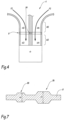
figure 4 is a scheme representative of the connection between the manifold and the turbine, the sealing of this connection being ensured a by a sealing gasket; -
figure 5 represents a schematic view of a first embodiment of the gasket; -
figure 6 represents a schematic view of a second embodiment of the gasket; -
figure 7 represents a partial sectional view of the gasket according to the cut line A-A offigures 5 and 6 -
Figure 1 represents, in side view, a vehicle which is, in the example, atractor truck 1. However, in a non-represented alternative embodiment, the vehicle may be different from a tractor truck. For instance, the vehicle may be a light, medium or heavy-duty vehicle, a utility vehicle, an autonomous vehicle, etc. - The
tractor truck 1 includes an internal combustion engine comprising an engine block (not represented) including a plurality of combustion cylinders, typically six cylinders. - The engine further includes an
exhaust gas manifold 4, represented onfigure 3 , which collects the gas exhausting from the combustion chambers of the engine cylinders. Typically, theexhaust gas manifold 4 includes six inlets 4.1, 4.2, 4.3, 4.4, 4.5 and 4.6 to be respectively connected to the combustion chambers of the engine. Exhaust gases coming from the first three cylinders, i.e. flowing in the inlets 4.1 to 4.3, are separated from exhaust gases coming from the three other cylinders, i.e. flowing in the inlets 4.4 to 4.6. Accordingly, themanifold 4 includes twogas flow channels flange 40 of themanifold 4. Bothgas flow channels wall 45 of themanifold 4. The dividingwall 45 extends up to the connectingflange 40. - The engine also includes a turbocharger 6 (cf.
figure 2 ) comprising a compressor part 6.1 and turbine part 6.2 that can be, for instance, a fixed geometry turbine (FGT). Turbine 6.2 converts the thermal and kinetic energies of the exhaust gases into a mechanical torque. Typically, the generated mechanical torque may be used to power the compressor part 6.1. According to an alternative of the invention that is not represented, the turbine 6.2 is not necessary part of a turbocharger and can be used to power another vehicle equipment such as, for instance, a pump. The turbine 6.2 includes two inletsgas flow channels gas flow channels exhaust gas manifold 4 via a connectingflange 60 of the turbine 6.2 and the connectingflange 40 of themanifold 4. - Both inlets
gas flow channels flange 60. The connectingflange 60 is provided with a dividingwall 65 to separate the inlets of thegas flow channels gasket 8, represented onfigure 5 , is used for sealing the connection between theflange 60 of the turbine and theflange 40 of themanifold 4. Thegasket 8 is in the form of theturbine flange 60 and is made of a single steel layer. - The
gasket 8 comprises twoflow passage openings wall 84 corresponding to the dividingwalls manifold 4 and of the turbine 6.2. - Preferably, there are only two flow passage openings. In the example, the two openings are of rectangular shape. However, any other shape is possible. Typically, the
openings - Advantageously, the
gasket 8 delimitsholes 92 for the passage of fixing bolts (not represented). - The
gasket 8 includes afirst sealing portion 86, represented schematically with broken lines, extending around the twoopenings portion 86 is a sealing bead that is integral with the rest of the gasket. In particular, this sealing bead forms a rectangle surrounding theopenings - The sealing gasket comprises also a
second sealing portion 88, represented schematically with broken lines, extending around theopening 82. The sealing gasket may comprise athird sealing portion 90, also represented schematically with broken lines, extending around theopening 80. Preferably, the sealingportions gasket 8. in particular, each sealing bead forms a rectangle surrounding theopening portions portions - Advantageously, sealing
portions portion 86. - Given that the sealing
beads gasket 8, thegasket 8 may be easily manufactured in one-piece, for example by stamping. - According to
claim 1, the gasket is made of a single steel layer. - On
figure 4 , arrows F2 represent the direction of the two respective gas flows coming from themanifold 4 and entering into the turbine 6.2. As shown on this figure, in assembled state, thechannel 42 communicates in a gas-tight manner withchannel 62 andchannel 44 communicates in a gas-tight manner withchannel 64. - For the clarity of the drawing, the
gasket 8 is represented onfigure 4 but the sealing beads are not represented. - Preferably, the
first sealing portion 86 and thesecond sealing portion 88 are designed differently, to compensate different deformation. When the sealinggasket 8 comprises a further third sealingportion 90, thefirst sealing portion 86 on the one hand and the second and thethird sealing portions - According to an improvement of the sealing
gasket 8, thefirst sealing portion 86 has a height H1 (figure 7 ) measured over the thickness of the plate and when it is in a rest state , that is to say in non-compressed state, that is higher than the height H2 of thesecond sealing portion 88. When the sealinggasket 8 comprises a further third sealingportion 90, thefirst sealing portion 86 has a height H1, measured over the thickness of the plate, (when it is not compressed) that is higher than the heights H2, H3 of the second andthird sealing portions - Owing to this, the thermal expansion of the dividing
walls flanges gasket 8 of afirst sealing portion 86 having a height H1 (figure 7 ) measured over the thickness of the plate that is higher than the heights H2, H3 of the second andthird sealing portions 88 90. Thanks to that, when the sealinggasket 8 is mounted on an engine and the engine is running, the contact pressure of thegasket 8 between theflange 40 and theflange 60 is maintained in the peripheral zone of the flanges that extends around the twoopenings walls flanges walls flanges - Preferably, the
first sealing portion 86 has a height H1, measured over the thickness of the plate, that is at least 20% higher than the height H2 of thesecond sealing portion 88. When the sealinggasket 8 comprises a further third sealingportion 90, thefirst sealing portion 8 has a height H1, measured over the thickness of the plate, that is at least 20% higher than the heights H2, H3 of the second andthird sealing portions first sealing portion 86 may have a height H1 that is comprised between 1.8 and 3.6 mm and thesecond sealing portion 88 and/or thethird sealing portion 90 may have a height H2, H3 that is comprised between 1,5 mm and 3 mm. - Preferably, the
second sealing portion 88 and thethird sealing portion 90 are designed to compensate amplitudes of the thermal deformations of the dividingwalls - Preferably, the height of the
first sealing portion 86 is determined such that in a compressed state of thefirst sealing portion 86, the height h1 of the first sealing portion 86 (measured over the thickness of the sealing gasket 8) is equal to the height h2 or h3 of the second or third sealingportion portion wall 84 such as met under operating conditions, that is to say when the sealinggasket 8 is mounted on the engine. Under operating conditions, the amplitude A of deformation of the second or third sealingportion walls walls exhaust manifold 4 when the engine is stop or just started and high temperatures of theexhaust manifold 4 met during some operations of the engine. The amplitude A is measured according to a direction that is perpendicular to the sealing gasket main surface. - The two sealing
beads wall 84, meaning that there is a double sealing between the twoopenings gasket 8. Accordingly to this improved arrangement, thegasket 8 according to the invention provides an improved sealing between the twogasket openings wall 84. - Preferably, sealing
portions gasket 8, meaning that a first group of three sealing portions are designed for being in sealing contact with themanifold flange 40 on one side of thegasket 8 and that a second group of three identical sealing portions are designed for being in sealing contact with theturbine flange 60 on the other side of thegasket 8. - Alternatively, and as shown on
figure 6 , thegasket 8 may include only two sealingportions - In a non-represented alternative embodiment, at least one sealing portion among the
first sealing portion 86, thesecond sealing portion 88 and thethird sealing portion 90 is a removable seal ring, typically a V-ring in steel. In particular, the seal ring may be received in a groove of the gasket.
Claims (9)
- Sealing gasket (8), for sealing a connection between an exhaust manifold (4) and a turbine (6.2) of a vehicle (1), the sealing gasket comprising two flow passage openings (80, 82) separated by a dividing wall (84) and a first sealing portion (86) extending around the two openings, in which the sealing gasket comprises at least a second sealing portion (88) extending around one (82) of the two openings, and a third sealing portion (90) extending around the other (80) of the two openings, each sealing portion (86, 88, 90) is a sealing bead, that is integral with the rest of the gasket, in which the sealing gasket (8) is in the form of a plate and sealing portions (86, 88, 90) protrude at least on one side of the plate, characterized in that the sealing gasket (8) is made of a single steel layer, and in that the first sealing portion (86) has a height (H1), measured over the thickness of the sealing gasket (8), that is at least 20% higher than the heights (H2, H3) of the second and third sealing portions (88, 90).
- Sealing gasket according to any previous claim, characterized in that sealing portions (86, 88, 90) are provided on both sides of the plate.
- Sealing gasket according to any previous claim, characterized in that the second sealing portion (88) and the third sealing portion (90) are two sealing beads that are each integral with the rest of the gasket and that are not merged in the region of the dividing wall (84).
- Sealing gasket according to any previous claim, characterized in that the gasket is made by stamping or molding.
- Sealing gasket according to any previous claim, characterized in that the first sealing portion (86) and the second sealing portion (88) are designed differently to compensate different deformation.
- Sealing gasket according to any previous claim, characterized in that the first sealing portion (86) on the one hand, and the second sealing portion (88) and the third sealing portion (90) on the other hand are designed differently to compensate different deformation.
- Sealing gasket according to any previous claim, characterized in that the height of the first sealing portion (86) is determined such that in a compressed state of the first sealing portion (86), the height (H1) of the first sealing portion (86), measured over the thickness of the sealing gasket (8), is equal to the height (h2, h3) of the second or third sealing portion (88, 90) when compressed plus a height (HA) corresponding to the maximum amplitude (A) of deformation of the second or third sealing portion (88, 90) at the dividing wall (84) such as met under operating conditions.
- Internal combustion engine, comprising an exhaust manifold (4), a turbine (6.2), and a sealing gasket (8) according to any previous claim, sealing the connection between the turbine and the manifold.
- Vehicle (1), such as a truck or a tractor truck, comprising an internal combustion engine according to previous claim.
Applications Claiming Priority (1)
| Application Number | Priority Date | Filing Date | Title |
|---|---|---|---|
| PCT/IB2017/001755 WO2019122947A1 (en) | 2017-12-20 | 2017-12-20 | Sealing gasket, for sealing the connection between an exhaust manifold and a turbine |
Publications (3)
| Publication Number | Publication Date |
|---|---|
| EP3728808A1 EP3728808A1 (en) | 2020-10-28 |
| EP3728808B1 true EP3728808B1 (en) | 2024-10-16 |
| EP3728808C0 EP3728808C0 (en) | 2024-10-16 |
Family
ID=61581355
Family Applications (1)
| Application Number | Title | Priority Date | Filing Date |
|---|---|---|---|
| EP17849812.7A Active EP3728808B1 (en) | 2017-12-20 | 2017-12-20 | Sealing gasket, for sealing the connection between an exhaust manifold and a turbine |
Country Status (4)
| Country | Link |
|---|---|
| US (1) | US11236660B2 (en) |
| EP (1) | EP3728808B1 (en) |
| CN (1) | CN111492128B (en) |
| WO (1) | WO2019122947A1 (en) |
Families Citing this family (4)
| Publication number | Priority date | Publication date | Assignee | Title |
|---|---|---|---|---|
| US11339715B2 (en) * | 2018-09-28 | 2022-05-24 | Fb Design S.R.L. | Turbocharger assembly |
| JP7794103B2 (en) * | 2022-11-01 | 2026-01-06 | トヨタ自動車株式会社 | Fastening structure and fastening structure design method |
| USD1063988S1 (en) * | 2023-06-26 | 2025-02-25 | Mason Martinez | Exhaust manifold for automotive vehicle |
| CN120159590A (en) * | 2023-12-15 | 2025-06-17 | 康明斯公司 | Exhaust manifold |
Citations (1)
| Publication number | Priority date | Publication date | Assignee | Title |
|---|---|---|---|---|
| US20060131817A1 (en) * | 2004-12-17 | 2006-06-22 | Kerelchuk Colin J | Gasket assembly for joints experiencing thermally induced movement |
Family Cites Families (25)
| Publication number | Priority date | Publication date | Assignee | Title |
|---|---|---|---|---|
| US5406795A (en) * | 1994-01-21 | 1995-04-18 | Cummins Engine Company, Inc. | Exhaust manifold to turbine casing flanges |
| JP3388030B2 (en) * | 1994-07-22 | 2003-03-17 | 本田技研工業株式会社 | Seal structure in exhaust system of internal combustion engine |
| US6540233B2 (en) * | 2001-04-20 | 2003-04-01 | Dana Corporation | Exhaust manifold gasket with integral heat sleeve |
| DE10258319A1 (en) * | 2002-12-13 | 2004-07-15 | Elringklinger Ag | Flat gasket, in particular exhaust manifold gasket, as well as such a gasket receiving assembly |
| US7401790B2 (en) * | 2005-01-11 | 2008-07-22 | Federal-Mogul World Wide, Inc. | Metal gasket with rigid seal |
| EP1862653A1 (en) * | 2005-03-24 | 2007-12-05 | Hitachi Metals, Ltd. | Exhaust system part |
| US20080143060A1 (en) * | 2006-12-15 | 2008-06-19 | Arvid Casler | Multi-layer gasket |
| FR2921696A1 (en) | 2007-09-27 | 2009-04-03 | Renault Sas | Turbocompressor fixing device for internal combustion engine of motor vehicle, has sealing joint arranged between flange and spacer to provide sealing of device and to guide operator while maintaining turbocompressor in suspension |
| DE202008010025U1 (en) * | 2008-07-25 | 2008-10-02 | Reinz-Dichtungs-Gmbh | Metallic seal, in particular exhaust manifold gasket |
| ATE552417T1 (en) | 2009-02-16 | 2012-04-15 | Caterpillar Motoren Gmbh & Co | TURBOCHARGED ENGINE WITH EXHAUST GAS RECYCLING |
| US20120227698A1 (en) * | 2010-02-19 | 2012-09-13 | Bhawani Sankar Tripathy | Multilayer gasket with extended rim labyrinth feature |
| US8474251B2 (en) * | 2010-10-19 | 2013-07-02 | Ford Global Technologies, Llc | Cylinder head cooling system |
| US20120139188A1 (en) * | 2010-12-02 | 2012-06-07 | Dana Automotive Systems Group, Llc | Exhaust Manifold Gasket |
| CN102108914A (en) | 2011-01-26 | 2011-06-29 | 重庆长安汽车股份有限公司 | Flat-face flange sealing gasket for automotive exhaust system |
| DE112012000347T5 (en) * | 2011-01-27 | 2013-09-12 | Borgwarner Inc. | Control valve arrangement |
| DE102011054354A1 (en) * | 2011-10-10 | 2013-04-11 | Elringklinger Ag | Flange for the connection of exhaust gas turboloader with turbine of multi-stage exhaust gas turboloader system of internal combustion engine, has exhaust gas-throughflow channel that is opened at flange-front side |
| JP6274384B2 (en) * | 2012-04-27 | 2018-02-07 | Nok株式会社 | Metal gasket and manufacturing method thereof |
| JP5757280B2 (en) * | 2012-10-15 | 2015-07-29 | トヨタ自動車株式会社 | Exhaust manifold mounting structure for internal combustion engines |
| CN203067776U (en) | 2013-02-02 | 2013-07-17 | 浙江华天机械有限公司 | Gasket of supercharger |
| DE102013104068A1 (en) * | 2013-04-22 | 2014-10-23 | Elringklinger Ag | gasket |
| DE102013211390B4 (en) | 2013-06-18 | 2015-08-06 | Eberspächer Exhaust Technology GmbH & Co. KG | Air gap insulated exhaust manifold and thus equipped supercharged internal combustion engine |
| DE102013011368A1 (en) * | 2013-07-09 | 2015-01-15 | Daimler Ag | Manifold gasket for an internal combustion engine of a motor vehicle |
| US9181848B2 (en) | 2014-02-24 | 2015-11-10 | Cummins Inc. | Turbocharger exhaust manifold system |
| JP6501540B2 (en) * | 2015-02-04 | 2019-04-17 | 本田技研工業株式会社 | Metal gasket |
| WO2017198316A1 (en) * | 2016-05-20 | 2017-11-23 | Volvo Truck Corporation | A conduit connection assembly with pressure relief |
-
2017
- 2017-12-20 US US16/955,941 patent/US11236660B2/en active Active
- 2017-12-20 CN CN201780097837.4A patent/CN111492128B/en active Active
- 2017-12-20 WO PCT/IB2017/001755 patent/WO2019122947A1/en not_active Ceased
- 2017-12-20 EP EP17849812.7A patent/EP3728808B1/en active Active
Patent Citations (1)
| Publication number | Priority date | Publication date | Assignee | Title |
|---|---|---|---|---|
| US20060131817A1 (en) * | 2004-12-17 | 2006-06-22 | Kerelchuk Colin J | Gasket assembly for joints experiencing thermally induced movement |
Also Published As
| Publication number | Publication date |
|---|---|
| US11236660B2 (en) | 2022-02-01 |
| WO2019122947A1 (en) | 2019-06-27 |
| US20200325812A1 (en) | 2020-10-15 |
| CN111492128A (en) | 2020-08-04 |
| EP3728808A1 (en) | 2020-10-28 |
| EP3728808C0 (en) | 2024-10-16 |
| CN111492128B (en) | 2022-10-25 |
Similar Documents
| Publication | Publication Date | Title |
|---|---|---|
| US11236660B2 (en) | Sealing gasket, for sealing the connection between an exhaust manifold and a turbine | |
| US8096772B2 (en) | Turbine vane for a gas turbine engine having serpentine cooling channels within the inner endwall | |
| US10458263B2 (en) | Turbine shroud with sealing features | |
| CN201739048U (en) | Air inlet manifold for multi-air cylinder internal combustion engine | |
| KR100476516B1 (en) | Exhaust gas turbine of an exhaust gas turbocharger | |
| US9683482B2 (en) | Turbocharger which is integrated into the cylinder head of an engine | |
| JPS6314164B2 (en) | ||
| JP5722798B2 (en) | Turbine housing for exhaust turbocharger of drive unit and method of manufacturing turbine housing | |
| JP2010038091A (en) | Internal combustion engine with supercharger | |
| EP2861856B1 (en) | Cylinder liner and piston engine | |
| US11035319B2 (en) | Sealing assembly comprising a cylinder head, a cylinder head gasket and a crankcase | |
| US11105295B2 (en) | Cylinder head with connected exhaust manifold of an internal combustion engine | |
| AU2005299862B2 (en) | Engine power assembly | |
| KR20190086566A (en) | A turbocharger having a sealing surface between the nozzle ring and the turbine housing | |
| KR101471514B1 (en) | Connection flange for a high pressure conduit | |
| CN204627734U (en) | Petrol engine forces cooling structure and petrol engine thereof | |
| CN103397932B (en) | Vehicle intercooler connecting tube | |
| CN116025546A (en) | Precooling structure of air compressor and air compressor | |
| CN214007339U (en) | Cylinder head and engine | |
| CN210217958U (en) | Engine gas circuit sealing system and engine | |
| JP4438523B2 (en) | Turbocharger and turbocharged engine | |
| US20260049660A1 (en) | Cylinder head gasket and cylinder liner for internal combustion engine | |
| EP3308009B1 (en) | Charge air cooler arrangement | |
| CN212927980U (en) | Exhaust manifold gasket and high-strength heat shield assembly | |
| US20260036078A1 (en) | Turbocharger housing and exhaust system comprising the same |
Legal Events
| Date | Code | Title | Description |
|---|---|---|---|
| STAA | Information on the status of an ep patent application or granted ep patent |
Free format text: STATUS: UNKNOWN |
|
| STAA | Information on the status of an ep patent application or granted ep patent |
Free format text: STATUS: THE INTERNATIONAL PUBLICATION HAS BEEN MADE |
|
| PUAI | Public reference made under article 153(3) epc to a published international application that has entered the european phase |
Free format text: ORIGINAL CODE: 0009012 |
|
| STAA | Information on the status of an ep patent application or granted ep patent |
Free format text: STATUS: REQUEST FOR EXAMINATION WAS MADE |
|
| 17P | Request for examination filed |
Effective date: 20200702 |
|
| AK | Designated contracting states |
Kind code of ref document: A1 Designated state(s): AL AT BE BG CH CY CZ DE DK EE ES FI FR GB GR HR HU IE IS IT LI LT LU LV MC MK MT NL NO PL PT RO RS SE SI SK SM TR |
|
| AX | Request for extension of the european patent |
Extension state: BA ME |
|
| DAV | Request for validation of the european patent (deleted) | ||
| DAX | Request for extension of the european patent (deleted) | ||
| STAA | Information on the status of an ep patent application or granted ep patent |
Free format text: STATUS: EXAMINATION IS IN PROGRESS |
|
| 17Q | First examination report despatched |
Effective date: 20210625 |
|
| GRAP | Despatch of communication of intention to grant a patent |
Free format text: ORIGINAL CODE: EPIDOSNIGR1 |
|
| STAA | Information on the status of an ep patent application or granted ep patent |
Free format text: STATUS: GRANT OF PATENT IS INTENDED |
|
| INTG | Intention to grant announced |
Effective date: 20240715 |
|
| GRAS | Grant fee paid |
Free format text: ORIGINAL CODE: EPIDOSNIGR3 |
|
| GRAA | (expected) grant |
Free format text: ORIGINAL CODE: 0009210 |
|
| STAA | Information on the status of an ep patent application or granted ep patent |
Free format text: STATUS: THE PATENT HAS BEEN GRANTED |
|
| AK | Designated contracting states |
Kind code of ref document: B1 Designated state(s): AL AT BE BG CH CY CZ DE DK EE ES FI FR GB GR HR HU IE IS IT LI LT LU LV MC MK MT NL NO PL PT RO RS SE SI SK SM TR |
|
| REG | Reference to a national code |
Ref country code: GB Ref legal event code: FG4D |
|
| REG | Reference to a national code |
Ref country code: DE Ref legal event code: R096 Ref document number: 602017085568 Country of ref document: DE Ref country code: CH Ref legal event code: EP |
|
| REG | Reference to a national code |
Ref country code: IE Ref legal event code: FG4D |
|
| U01 | Request for unitary effect filed |
Effective date: 20241114 |
|
| U07 | Unitary effect registered |
Designated state(s): AT BE BG DE DK EE FI FR IT LT LU LV MT NL PT RO SE SI Effective date: 20241121 |
|
| U20 | Renewal fee for the european patent with unitary effect paid |
Year of fee payment: 8 Effective date: 20241121 |
|
| PG25 | Lapsed in a contracting state [announced via postgrant information from national office to epo] |
Ref country code: IS Free format text: LAPSE BECAUSE OF FAILURE TO SUBMIT A TRANSLATION OF THE DESCRIPTION OR TO PAY THE FEE WITHIN THE PRESCRIBED TIME-LIMIT Effective date: 20250216 Ref country code: HR Free format text: LAPSE BECAUSE OF FAILURE TO SUBMIT A TRANSLATION OF THE DESCRIPTION OR TO PAY THE FEE WITHIN THE PRESCRIBED TIME-LIMIT Effective date: 20241016 |
|
| PG25 | Lapsed in a contracting state [announced via postgrant information from national office to epo] |
Ref country code: ES Free format text: LAPSE BECAUSE OF FAILURE TO SUBMIT A TRANSLATION OF THE DESCRIPTION OR TO PAY THE FEE WITHIN THE PRESCRIBED TIME-LIMIT Effective date: 20241016 |
|
| PG25 | Lapsed in a contracting state [announced via postgrant information from national office to epo] |
Ref country code: NO Free format text: LAPSE BECAUSE OF FAILURE TO SUBMIT A TRANSLATION OF THE DESCRIPTION OR TO PAY THE FEE WITHIN THE PRESCRIBED TIME-LIMIT Effective date: 20250116 |
|
| PG25 | Lapsed in a contracting state [announced via postgrant information from national office to epo] |
Ref country code: GR Free format text: LAPSE BECAUSE OF FAILURE TO SUBMIT A TRANSLATION OF THE DESCRIPTION OR TO PAY THE FEE WITHIN THE PRESCRIBED TIME-LIMIT Effective date: 20250117 |
|
| PG25 | Lapsed in a contracting state [announced via postgrant information from national office to epo] |
Ref country code: PL Free format text: LAPSE BECAUSE OF FAILURE TO SUBMIT A TRANSLATION OF THE DESCRIPTION OR TO PAY THE FEE WITHIN THE PRESCRIBED TIME-LIMIT Effective date: 20241016 |
|
| PG25 | Lapsed in a contracting state [announced via postgrant information from national office to epo] |
Ref country code: RS Free format text: LAPSE BECAUSE OF FAILURE TO SUBMIT A TRANSLATION OF THE DESCRIPTION OR TO PAY THE FEE WITHIN THE PRESCRIBED TIME-LIMIT Effective date: 20250116 |
|
| PG25 | Lapsed in a contracting state [announced via postgrant information from national office to epo] |
Ref country code: SM Free format text: LAPSE BECAUSE OF FAILURE TO SUBMIT A TRANSLATION OF THE DESCRIPTION OR TO PAY THE FEE WITHIN THE PRESCRIBED TIME-LIMIT Effective date: 20241016 |
|
| PG25 | Lapsed in a contracting state [announced via postgrant information from national office to epo] |
Ref country code: MC Free format text: LAPSE BECAUSE OF FAILURE TO SUBMIT A TRANSLATION OF THE DESCRIPTION OR TO PAY THE FEE WITHIN THE PRESCRIBED TIME-LIMIT Effective date: 20241016 |
|
| PG25 | Lapsed in a contracting state [announced via postgrant information from national office to epo] |
Ref country code: SK Free format text: LAPSE BECAUSE OF FAILURE TO SUBMIT A TRANSLATION OF THE DESCRIPTION OR TO PAY THE FEE WITHIN THE PRESCRIBED TIME-LIMIT Effective date: 20241016 |
|
| PG25 | Lapsed in a contracting state [announced via postgrant information from national office to epo] |
Ref country code: CZ Free format text: LAPSE BECAUSE OF FAILURE TO SUBMIT A TRANSLATION OF THE DESCRIPTION OR TO PAY THE FEE WITHIN THE PRESCRIBED TIME-LIMIT Effective date: 20241016 |
|
| REG | Reference to a national code |
Ref country code: CH Ref legal event code: PL |
|
| PLBE | No opposition filed within time limit |
Free format text: ORIGINAL CODE: 0009261 |
|
| STAA | Information on the status of an ep patent application or granted ep patent |
Free format text: STATUS: NO OPPOSITION FILED WITHIN TIME LIMIT |
|
| 26N | No opposition filed |
Effective date: 20250717 |
|
| GBPC | Gb: european patent ceased through non-payment of renewal fee |
Effective date: 20250116 |
|
| PG25 | Lapsed in a contracting state [announced via postgrant information from national office to epo] |
Ref country code: GB Free format text: LAPSE BECAUSE OF NON-PAYMENT OF DUE FEES Effective date: 20250116 |
|
| PG25 | Lapsed in a contracting state [announced via postgrant information from national office to epo] |
Ref country code: CH Free format text: LAPSE BECAUSE OF NON-PAYMENT OF DUE FEES Effective date: 20241231 |
|
| PG25 | Lapsed in a contracting state [announced via postgrant information from national office to epo] |
Ref country code: IE Free format text: LAPSE BECAUSE OF NON-PAYMENT OF DUE FEES Effective date: 20241220 |
|
| U20 | Renewal fee for the european patent with unitary effect paid |
Year of fee payment: 9 Effective date: 20251223 |