EP3728803B1 - A valve actuation system for an internal combustion engine - Google Patents
A valve actuation system for an internal combustion engine Download PDFInfo
- Publication number
- EP3728803B1 EP3728803B1 EP17826515.3A EP17826515A EP3728803B1 EP 3728803 B1 EP3728803 B1 EP 3728803B1 EP 17826515 A EP17826515 A EP 17826515A EP 3728803 B1 EP3728803 B1 EP 3728803B1
- Authority
- EP
- European Patent Office
- Prior art keywords
- valve
- rocker
- reset
- actuation system
- lever
- Prior art date
- Legal status (The legal status is an assumption and is not a legal conclusion. Google has not performed a legal analysis and makes no representation as to the accuracy of the status listed.)
- Active
Links
Images



Classifications
-
- F—MECHANICAL ENGINEERING; LIGHTING; HEATING; WEAPONS; BLASTING
- F01—MACHINES OR ENGINES IN GENERAL; ENGINE PLANTS IN GENERAL; STEAM ENGINES
- F01L—CYCLICALLY OPERATING VALVES FOR MACHINES OR ENGINES
- F01L13/00—Modifications of valve-gear to facilitate reversing, braking, starting, changing compression ratio, or other specific operations
- F01L13/06—Modifications of valve-gear to facilitate reversing, braking, starting, changing compression ratio, or other specific operations for braking
- F01L13/065—Compression release engine retarders of the "Jacobs Manufacturing" type
-
- F—MECHANICAL ENGINEERING; LIGHTING; HEATING; WEAPONS; BLASTING
- F01—MACHINES OR ENGINES IN GENERAL; ENGINE PLANTS IN GENERAL; STEAM ENGINES
- F01L—CYCLICALLY OPERATING VALVES FOR MACHINES OR ENGINES
- F01L1/00—Valve-gear or valve arrangements, e.g. lift-valve gear
- F01L1/02—Valve drive
- F01L1/04—Valve drive by means of cams, camshafts, cam discs, eccentrics or the like
- F01L1/047—Camshafts
- F01L1/053—Camshafts overhead type
-
- F—MECHANICAL ENGINEERING; LIGHTING; HEATING; WEAPONS; BLASTING
- F01—MACHINES OR ENGINES IN GENERAL; ENGINE PLANTS IN GENERAL; STEAM ENGINES
- F01L—CYCLICALLY OPERATING VALVES FOR MACHINES OR ENGINES
- F01L1/00—Valve-gear or valve arrangements, e.g. lift-valve gear
- F01L1/12—Transmitting gear between valve drive and valve
- F01L1/18—Rocking arms or levers
-
- F—MECHANICAL ENGINEERING; LIGHTING; HEATING; WEAPONS; BLASTING
- F01—MACHINES OR ENGINES IN GENERAL; ENGINE PLANTS IN GENERAL; STEAM ENGINES
- F01L—CYCLICALLY OPERATING VALVES FOR MACHINES OR ENGINES
- F01L1/00—Valve-gear or valve arrangements, e.g. lift-valve gear
- F01L1/12—Transmitting gear between valve drive and valve
- F01L1/18—Rocking arms or levers
- F01L1/181—Centre pivot rocking arms
-
- F—MECHANICAL ENGINEERING; LIGHTING; HEATING; WEAPONS; BLASTING
- F01—MACHINES OR ENGINES IN GENERAL; ENGINE PLANTS IN GENERAL; STEAM ENGINES
- F01L—CYCLICALLY OPERATING VALVES FOR MACHINES OR ENGINES
- F01L1/00—Valve-gear or valve arrangements, e.g. lift-valve gear
- F01L1/26—Valve-gear or valve arrangements, e.g. lift-valve gear characterised by the provision of two or more valves operated simultaneously by same transmitting-gear; peculiar to machines or engines with more than two lift-valves per cylinder
-
- F—MECHANICAL ENGINEERING; LIGHTING; HEATING; WEAPONS; BLASTING
- F01—MACHINES OR ENGINES IN GENERAL; ENGINE PLANTS IN GENERAL; STEAM ENGINES
- F01L—CYCLICALLY OPERATING VALVES FOR MACHINES OR ENGINES
- F01L1/00—Valve-gear or valve arrangements, e.g. lift-valve gear
- F01L1/26—Valve-gear or valve arrangements, e.g. lift-valve gear characterised by the provision of two or more valves operated simultaneously by same transmitting-gear; peculiar to machines or engines with more than two lift-valves per cylinder
- F01L1/267—Valve-gear or valve arrangements, e.g. lift-valve gear characterised by the provision of two or more valves operated simultaneously by same transmitting-gear; peculiar to machines or engines with more than two lift-valves per cylinder with means for varying the timing or the lift of the valves
-
- F—MECHANICAL ENGINEERING; LIGHTING; HEATING; WEAPONS; BLASTING
- F01—MACHINES OR ENGINES IN GENERAL; ENGINE PLANTS IN GENERAL; STEAM ENGINES
- F01L—CYCLICALLY OPERATING VALVES FOR MACHINES OR ENGINES
- F01L13/00—Modifications of valve-gear to facilitate reversing, braking, starting, changing compression ratio, or other specific operations
- F01L13/06—Modifications of valve-gear to facilitate reversing, braking, starting, changing compression ratio, or other specific operations for braking
-
- F—MECHANICAL ENGINEERING; LIGHTING; HEATING; WEAPONS; BLASTING
- F01—MACHINES OR ENGINES IN GENERAL; ENGINE PLANTS IN GENERAL; STEAM ENGINES
- F01L—CYCLICALLY OPERATING VALVES FOR MACHINES OR ENGINES
- F01L1/00—Valve-gear or valve arrangements, e.g. lift-valve gear
- F01L1/02—Valve drive
- F01L1/04—Valve drive by means of cams, camshafts, cam discs, eccentrics or the like
- F01L1/08—Shape of cams
-
- F—MECHANICAL ENGINEERING; LIGHTING; HEATING; WEAPONS; BLASTING
- F01—MACHINES OR ENGINES IN GENERAL; ENGINE PLANTS IN GENERAL; STEAM ENGINES
- F01L—CYCLICALLY OPERATING VALVES FOR MACHINES OR ENGINES
- F01L1/00—Valve-gear or valve arrangements, e.g. lift-valve gear
- F01L1/02—Valve drive
- F01L1/04—Valve drive by means of cams, camshafts, cam discs, eccentrics or the like
- F01L1/047—Camshafts
- F01L1/053—Camshafts overhead type
- F01L2001/0537—Double overhead camshafts [DOHC]
-
- F—MECHANICAL ENGINEERING; LIGHTING; HEATING; WEAPONS; BLASTING
- F01—MACHINES OR ENGINES IN GENERAL; ENGINE PLANTS IN GENERAL; STEAM ENGINES
- F01L—CYCLICALLY OPERATING VALVES FOR MACHINES OR ENGINES
- F01L2820/00—Details on specific features characterising valve gear arrangements
- F01L2820/01—Absolute values
Definitions
- the invention relates to a valve actuation system for an internal combustion engine, to an engine arrangement comprising such a valve actuation system, and to a vehicle comprising such a system or arrangement.
- the invention can be applied in heavy-duty and medium-duty vehicles, such as trucks, buses and construction equipment.
- An internal combustion engine conventionally comprises several cylinders, each provided with at least one intake valve and at least one exhaust valve.
- Such an engine can further be equipped with a valve actuation system, especially for performing an engine brake function.
- the valve actuation system comprises a rocker mounted on a rocker shaft for operating the exhaust valves, a camshaft with a cam for each rocker, said cam cooperating with a cam follower at one end of the rocker.
- a valve play take-up device arranged between an opposite end of the rocker and the exhaust valve, comprises a piston able to urge at least one exhaust valve towards its open position.
- the valve play take-up device is configured for taking-up a play between the piston and the exhaust valve.
- the piston received in a chamber disposed in said opposite rocker end, and a hydraulic circuit with valve means for supplying or draining a fluid to and from said chamber.
- the hydraulic circuit comprises a reset valve which, in an active position, causes the fluid to be drained out of the chamber.
- the piston slides in the chamber away from the valve, so that the play between the piston and the valve reappears.
- the reset valve is activated, the piston is therefore moved in a rest or deactivated position.
- the deactivation of the piston appears when the engine brake function is used.
- the deactivation of the piston is instantaneously and occurs during a period of the cam revolution.
- the reset valve can be moved from an inactive position to the above described active position by means of a lever.
- the lever can be mounted around a pivot axis and can be pivoted by a reset cam cooperating with a cam follower at one end of the lever, thereby causing the pivoting of the reset valve.
- WO2013/005070 discloses corresponding closest prior art.
- An object of the invention is to provide a valve actuation system that improves the known systems with respect to at least one of the above mentioned drawbacks.
- the invention relates to a valve actuation system for an internal combustion engine, said valve actuation system comprising:
- the transmission ratio is the ratio between the reset valve angular velocity and the lever angular velocity.
- the invention only requires a limited rotation of the lever, as compared with prior art devices. Consequently, the invention is advantageous in terms of packaging, as it can be implemented in limited spaces.
- the invention requires a lower moment arm to achieve the necessary range of motion for the reset valve between its inactive position to its active position.
- inertia and imbalance issues are limited, and a weight gain is obtained for the whole valve actuation system.
- the components of the valve actuation system are subjected to lesser mechanical forces, which results in a more robust system having a longer service life.
- This advantage is enhanced by the fact that the main components are rotating parts, and that their cooperation does not combine translations and rotations, as such a movement combination is generally detrimental to robustness.
- the invention further makes it possible to improve mechanical efficiency as well as the lever guidance - as the lever is guided around a fixed part.
- cam and the reset cam are separate parts, even if their rotation movements are identical as they can be fixedly mounted on a same shaft.
- rocker and the lever are also separate parts, which are not secured to one another. The movements of the rocker and lever are different, even if the pivot axes are identical and if the cam and reset cams are fixedly mounted on a same shaft.
- the lever which can be arranged on the side of the rocker, can be used as a spacer to keep the rocker in position.
- the extended position of the piston can result in the activation of an engine brake function, whereas in the retracted position of the piston, a gap is provided between the piston and the valve (or an opening member secured to valve), thus preventing the piston to open the valve when the driven end portion of the rocker contacts an auxiliary bump of the cam.
- the transmission ratio can range from 2 to 15.
- a lower ratio would be difficult to implement due to available space limitations (camshaft diameter, radial dimension of the reset cam bump, angle of the reset valve, limited space below the valve actuation system, etc.).
- a higher ratio would require too precise dimension tolerances, or would lead to adjustment difficulties, or would impair repeatability.
- the transmission ratio can preferably range from 3.6 to 9.
- the lever cannot rotate by more than 15°, which makes the minimum ratio around 3.6.
- the maximum value of 9 has been calculated taking into account the gear module, as well as the minimum number of teeth pertaining to an example of the rotational coupling means to ensure a satisfactory sustainability and an angle of motion large enough to provide the required movement of the reset valve without requiring too precise tolerances.
- a ratio around 9 results from a rotation of the lever by about 6°.
- the transmission ratio is around 5.5.
- the rocker and the lever are pivotably mounted around one and the same pivot axis.
- the reset valve it can be mounted about an axis which is parallel to the pivot axis.
- the lever comprises a portion having a cylindrical outer surface provided with teeth
- the reset valve comprises a rod which protrudes outside the rocker towards the lever and which is provided with teeth, the teeth of the lever and the teeth of the reset valve forming at least part of the coupling means.
- the lever driven end portion may comprise a leg which protrudes substantially radially away from the pivot axis, said leg having a free end adapted to be in contact with the reset cam.
- the valve actuation system may further comprise an activation member which is fixedly mounted on the rocker actuating end portion in operation, said activation member being adapted to cooperate with a valve bridge for simultaneously opening two valves of the engine following the cooperation of the driven end portion with the cam main bump.
- an activation member which is fixedly mounted on the rocker actuating end portion in operation, said activation member being adapted to cooperate with a valve bridge for simultaneously opening two valves of the engine following the cooperation of the driven end portion with the cam main bump.
- the position of the activation member with respect to the rocker can be preliminary set by an appropriate means, such as an adjusting screw, and can be changed if need be, for example during maintenance.
- the valve actuation system is an exhaust valve actuation system.
- the piston allows activating an engine brake function when it is in its extended position.
- the invention further relates to an engine arrangement comprising:
- the pivot axis may be parallel to the camshaft axis.
- the engine arrangement may further comprise a valve bridge moveable by the activation member for simultaneously opening the two valves, wherein the valve bridge comprises a hole through which is slidably engaged an opening member secured to the valve, and operable by the piston, so that the piston is able to open only one valve.
- the invention also relates to a vehicle which comprises a valve actuation system as previously described or an engine arrangement as previously described.
- the invention relates to an engine arrangement 1 of a non-represented automotive vehicle.
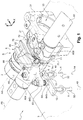
- the engine arrangement 1 comprises a cylinder head 3 of an internal combustion engine of the vehicle, on which cylinder head 3 is secured a bracket 31 for mounting a valve actuation system S, i.e. a camshaft 2.
- the cylinder head 3 includes openings 32 for receiving the valves of the engine.
- each cylinder of the engine is equipped with two inlet valves (not shown), and two exhaust valves 4, 5, namely an inner exhaust valve 4 and an outer exhaust valve 5.
- the valves have respective axes A4, A5.
- Valves 4 and 5 are kept in a closed position by respective springs 41 and 51 (not shown on figure 1 , but visible on figures 3 and 10a , for example). Each valve 4 and 5 is movable in translation along its respective axis A4, A5 so as to be opened, or lifted. More precisely, translation of valves 4 and 5 opens a passageway between the combustion chamber of the cylinder and an exhaust manifold. Valves 4 and 5 are partly represented on figures 1 and 3 , only their respective stems being visible.
- the engine arrangement 1 also comprises the camshaft 2 having an axis A2, said camshaft 2 being rotatably mounted around its axis A2 in an opening 33 of the bracket 31.
- On the camshaft 2 are fastened cams for moving the cylinder valves, among which one cam 21 dedicated to move the exhaust valves 4, 5 of each cylinder.
- the cam 21 includes a main bump 210 and at least one auxiliary bump having a smaller radial dimension than the main bump 210.
- the bumps are valve lift sectors where the cam profile exhibits a bigger eccentricity with respect to axis A2 than the base radius of the cam 21.
- the cam 21 comprises two auxiliary bumps 211, 212 (see figure 10b ).
- a reset cam 26 including at least one bump 260 is also fastened on the camshaft 2.
- the reset cam 26 is offset with respect to cam 21 along axis A2.
- longitudinal axis X is defined as being parallel to axis A2 of the camshaft, vertical axis Z as being parallel to axes A4, A5 of the valves 4, 5 and transverse axis Y as being orthogonal to axes X and Z. It has to be noted that the term “vertical” is used for simplifying the description, but does not limit the possible orientation of the engine arrangement 1.
- the valve actuation system S comprises a rocker 6 which is pivotably mounted around a pivot axis A6 and a lever 7 which is also pivotably mounted around a pivot axis.
- the rocker 6 and the lever 7 are pivotably mounted around one and the same pivot axis A6, although their pivoting movements are different.
- a rocker shaft 61 is rotatably mounted around its axis A6 on the bracket 31.
- the rocker 6 is secured to the rocker arm shaft 61 whereas the lever 7 is able to rotate around the rocker arm shaft 61.
- the lever 7 is mounted adjacent a side face of the rocker 6 along axis A6.
- the rocker 6 comprises a driven end portion 62 adapted to cooperate with the cam 21, i.e. to follow the peripheral face of said cam 21.
- the driven end portion 62 can comprise a roller.
- the rocker 6 also comprises an actuating end portion 63 located opposite the driven end portion 62 relative to axis A6.
- the actuating end portion 63 comprises a fixed activation member 64 and a sliding piston 8.
- the activation member 64 has an axis A64 parallel to the valve axes A4, A5.
- the activation member 64 comprises a rod 641 the position of which, along Z, can be adjusted relative the rocker 6 by means of an adjusting screw 642. However, in operation, the activation member 64 is fixedly mounted on the rocker 6.
- the free end of rod 641 facing the cylinder block 3 is equipped with a pad 643 through a ball joint coupling.
- the activation member 64 is adapted to cooperate with a valve bridge 12 which cooperates with both valves 4, 5, so as to simultaneously open said valves 4, 5 following the cooperation of the driven end portion 62 of the rocker 6 with the cam main bump 210.
- the valve bridge 12 forms a valve opening actuator, and extends substantially perpendicularly to axes A4 and A5.
- the piston 8 has an axis A8 parallel to the valve axes A4, A5.
- the piston 8 is housed in a chamber 81 of the rocker 6, and can slide inside said chamber 81 along axis A8.
- the piston 8 comprises a member 82 protruding towards the cylinder block 3.
- the piston axis A8 is aligned with the inner valve axis A4.
- An opening member 40 secured to the valve 4 is slidably engaged in a hole 13 arranged in the valve bridge 12.
- the opening member 40 is operable by the piston 8, so that the piston 8 is able to open only the inner valve 4, following the cooperation of the driven end portion 62 of the rocker 6 with a bump of the cam 21, as will be explained later. More specifically, as it will be explained below in more detail, the piston 8 is slidably mounted relative the rocker 6, inside chamber 81, between:
- the rocker 6 comprises a fluid circuit for providing a fluid, such as pressurized oil, to chamber 81, in order to cause the piston 8 to move from its retracted position to its extended position.
- the fluid circuit is internally arranged in rocker 6.
- rocker shaft 61 is hollow and defines a duct 611 ( figure 3 ) which is connected to a non-shown fluid tank, and to the chamber 81 housing piston 8, via a check valve 97 ( figure 6 ).
- check valve 97 is opened so that fluid can flow from duct 611 to the inside of rocker 6 and subsequently to the chamber 81 so as to induce a pressure raise and cause piston 8 to be moved towards its extended position.
- the fluid circuit comprises a main duct 103 which is connected to the duct 611 inside rocker shaft 61 via an inlet duct 102 ( figure 8 ), and which fluidly links check-valve 97 with the chamber 81.
- Main duct 103 opens on the outside of rocker 6 and fluid is prevented from going out of rocker 6 by a shutter element 105 screwed into a threaded portion of main duct 103.
- the main duct successively comprises an enlarged portion 114 ( figure 6 ), an intermediate portion 116, and an outlet portion 118 opening in the camber 81.
- a seat element 107 is press-fitted into main duct 103, in intermediate portion 116.
- a ball 109 of check-valve 97 is adapted to cooperate with seat element 107 so as to block passage of fluid from piston chamber 81 back to duct 611, and thus maintain piston 8 in its extended position when the piston 8 is pushing the opening member 40.
- Ball 109 is biased towards seat element 107 by a spring 111 arranged in the outlet portion 118, and therefore tends to close the check-valve 97.
- Ball 109 is kept in open position by a plunger 110 spring-biased by a spring 112 arranged in the enlarged portion 114, the action of the spring 112 being superior to the action of spring 111.
- the inlet duct 102 is connected to the enlarged portion 114, in an area called chamber 113 which is located on the side of the plunger 110 opposite the spring 112. In other words, fluid coming from duct 611 first flows into chamber 113.
- the rocker 6 also comprises a reset circuit for draining the fluid out of the chamber 81 of fluid circuit to allow the piston 8 to move towards its retracted position.
- the reset circuit comprises a by-pass duct 115 ( figures 6 to 9 ) which originates from main duct 103, more specifically from the outlet portion 118 of main duct 103, i.e. between the ball 109 and the chamber 81, and which opens on the outside of rocker 6, to the rocker shaft 61.
- a reset valve 99 which is mounted relative to the rocker 6.
- an upstream portion 115a of the by-pass duct 115 is defined between the main duct 103 and the reset valve 99, and a downstream portion 115b of the by-pass duct 115 is defined between the reset valve 99 and the outside of rocker 6.
- the reset valve 99 is distinct from the check valve 97, and is adapted to rotate around its axis A99 which is parallel to axis A6.
- the reset valve 99 comprises an inside passage 98 for allowing fluid communication between the upstream portion 115a and the downstream portion 115b of the by-pass duct 115.
- reset valve 99 is rotatably mounted relative to the rocker 6 between an inactive position ( figure 8 ), in which the main duct 103 and the downstream portion 115b of the by-pass duct 115 are not in fluid communication, and an active position ( figure 9 ) in which the reset valve 99 opens the by-pass duct 115 so that the fluid can be drained out of the fluid circuit.
- the inside passage 98 can be a hollow sector, as shown on figure 8 for example, or can comprise two orthogonal bores, as shown on figures 10b , 11b, 12b, 13b . Other implementations can be envisaged.
- the lever 7 has a driven end portion 72 adapted to cooperate with the reset cam 26, i.e. to follow the peripheral face of said cam 26.
- the driven end portion 72 comprises a leg which protrudes substantially radially away from the pivot axis A6, the free end of said leg 72 being adapted to be in contact with the reset cam 26.
- the lever 7 also comprises an actuating end portion 73 for rotating the reset valve 99 from its inactive position towards its active position following the cooperation of the lever driven end portion 72 with the bump 260 of the reset cam 26.
- the lever 7 comprises a ring-shaped portion 74 engaged around the rocker shaft 61, and from which protrudes the leg 72.
- the ring-shaped portion 74 has a cylindrical outer surface on which is provided the actuating end portion 73. More specifically, in an embodiment, said cylindrical outer surface is provided with teeth 75 extending parallel to axis A6.
- An elastic member 71 such as represented in figure 2 , or an elastic member 11 , such as represented in figure 1 , may be provided to ensure the driven end portion 72 is maintained in contact with the reset cam 26.
- the elastic member 71 can be configured as a leaf having one portion fastened to the leg 72 of lever 7 and one portion secured to the bracket 31.
- the elastic member 11 can be configured as a latch pushing a pin 77 of the lever 7, wherein the pin 77 extends in parallel to the axis A6 and extends from the ring-shaped portion 74.
- the reset valve 99 comprises a rod 91 ( figure 7 ) which protrudes outside the rocker 6 towards the lever 7, parallel to axis A6. Said rod 91 is provided with teeth 95 extending parallel to axis A6. The teeth 75 of the lever 7 and the teeth 95 of the reset valve 99 form rotational coupling means between the lever 7 and the reset valve 99.
- the rotational coupling means are configured to provide a transmission ratio greater than 1.
- the transmission ratio can range from 2 to 15, preferably from 3.6 to 9, said transmission ratio being for example around 5.5.
- valve actuation system S can be dimensioned as follows:
- a 10° rotation of lever 7 can lead to a 54° rotation of the reset valve 99, which corresponds to a transmission ratio of 5.4.
- the maximum rotation of the lever 7 can be around 15°.
- the dedicated reset cam 26 is adapted to create a relative movement of the lever 7, and thus of the reset valve 99, with respect to the corresponding rocker 6. This relative movement is nevertheless coordinated with the movement of the rocker 6 with respect to the engine housing, so that the reset function is performed at a selected given time within the opening/closing cycle of the valves 4 and 5.
- check valve 97 When the engine brake function is not activated ( figure 9 ), check valve 97 is in opened position, due to action of the spring biased plunger 110, and piston 8 is retracted in chamber 81.
- a gap g1 is provided between member 82 of piston 2 and the opening member 40 of valve 4.
- the driven end portion 62 is in contact with the peripheral face of said cam 21.
- the rocker 6 pivoting movement is not sufficient, because of gap g1, to make member 82 come in contact with opening member 40.
- the valve opening movement thus only results from the cooperation of activation member 64 and valve bridge 12, following the contact between the rocker 6 and the main bump 210 of cam 21.
- FIGS. 10a-15b show the valve actuation system S at various moments of the engine cycle.
- Figures 10a , 11a, 12a, 13a , 14a , 15a show the position of the lever 7 cooperating with reset cam 26, while figures 10b , 11b, 12b, 13b , 14b , 15b show the position of the rocker 6 cooperating with cam 21 at the respective corresponding moments.
- Camshaft 2, cam 21 and reset cam 26 rotate together around axis A2 according to arrow R shown on figures 10a-15b .
- roller 62 can come in contact with a further auxiliary bump 212 of cam 21 (this phase not being illustrated).
- leg 72 of lever 7 remains in contact with the bump 260 of reset cam 26.
- the bump 260 has angular range that angularly extends beyond the main bump 210 of cam 21 and up to a corner 261 of the bump 260. It results from this difference that the rocker 6 rotates with respect to the lever 7, in other words an angular offset is created between the rocker 6 and the lever 7, causing the reset valve 99 to begin to rotate, in function of the pre-determined transmission ratio between the lever 7 and the reset valve 99, around axis A99, towards its active position.
- the reset valve 99 begins to open whereas the check valve 97 is still closed and the reset valve 99 reaches its active position, preferably before the roller 62 of rocker 6 comes in contact with the base radius portion of cam 21. As soon as the reset valve 99 begins to open, the fluid circuit starts being drained through the by-pass duct 115 and piston 8 moves back to its retracted position.
- Figure 16 shows the valve lifts as a function of the camshaft rotation, namely:
- CP1 is the cam position corresponding to auxiliary bump 211: owing to the slight opening of valve 4, more air is added in the cylinder chamber at the beginning of the compression phase.
- CP2 is the cam position corresponding to auxiliary bump 212: owing to the slight opening of valve 4, air is decompressed out of the cylinder chamber in the decompression phase, just before the top dead centre (TDC).
- the reset valve 99 allows closing the inner exhaust valve 4 at the same time as the outer exhaust valve 5, i.e. causes an asymmetric movement profile of valve 4.
- overlap O is reduced as schematically illustrated by arrow O on figure 15 . Reducing overlap, i.e. the time period when both the intake and exhaust valves are open, allows improving the engine brake effect.
Landscapes
- Engineering & Computer Science (AREA)
- Mechanical Engineering (AREA)
- General Engineering & Computer Science (AREA)
- Valve Device For Special Equipments (AREA)
- Valve-Gear Or Valve Arrangements (AREA)
Description
- The invention relates to a valve actuation system for an internal combustion engine, to an engine arrangement comprising such a valve actuation system, and to a vehicle comprising such a system or arrangement.
- The invention can be applied in heavy-duty and medium-duty vehicles, such as trucks, buses and construction equipment.
- An internal combustion engine conventionally comprises several cylinders, each provided with at least one intake valve and at least one exhaust valve. Such an engine can further be equipped with a valve actuation system, especially for performing an engine brake function. To that end, for each cylinder, the valve actuation system comprises a rocker mounted on a rocker shaft for operating the exhaust valves, a camshaft with a cam for each rocker, said cam cooperating with a cam follower at one end of the rocker. A valve play take-up device, arranged between an opposite end of the rocker and the exhaust valve, comprises a piston able to urge at least one exhaust valve towards its open position. The valve play take-up device is configured for taking-up a play between the piston and the exhaust valve. The piston received in a chamber disposed in said opposite rocker end, and a hydraulic circuit with valve means for supplying or draining a fluid to and from said chamber.
- More specifically, the hydraulic circuit comprises a reset valve which, in an active position, causes the fluid to be drained out of the chamber. As a result, the piston slides in the chamber away from the valve, so that the play between the piston and the valve reappears. When the reset valve is activated, the piston is therefore moved in a rest or deactivated position. The deactivation of the piston appears when the engine brake function is used. The deactivation of the piston is instantaneously and occurs during a period of the cam revolution.
- The reset valve can be moved from an inactive position to the above described active position by means of a lever. For example, the lever can be mounted around a pivot axis and can be pivoted by a reset cam cooperating with a cam follower at one end of the lever, thereby causing the pivoting of the reset valve.
-
WO2013/005070 discloses corresponding closest prior art. - However, the known arrangements are not fully satisfactory, especially in terms of compactness, sustainability and/or mechanical efficiency.
- It therefore appears that, from several standpoints, there is room for improvement in valve actuation systems.
- An object of the invention is to provide a valve actuation system that improves the known systems with respect to at least one of the above mentioned drawbacks.
- To that end, according to a first aspect, the invention relates to a valve actuation system for an internal combustion engine, said valve actuation system comprising:
- a rocker pivotably mounted around a pivot axis and having:
- a driven end portion adapted to cooperate with a rotating cam including a main bump and at least one auxiliary bump having a smaller radial dimension than the main bump;
- an actuating end portion equipped with at least one piston adapted to open at least one valve of the engine following the cooperation of the driven end portion with a bump of the cam, the piston being slidably mounted relative to the rocker between an extended position allowing said piston to open said valve when the driven end portion contacts the auxiliary bump, and a retracted position preventing said piston to open said valve when the driven end portion contacts the auxiliary bump;
- the rocker comprising:
- a fluid circuit for providing a fluid in order to cause the piston to move from its retracted position to its extended position;
- a reset circuit comprising a reset valve rotatably mounted relative to the rocker, between an inactive position, and an active position in which the reset valve causes the fluid to be drained out of the fluid circuit to allow the piston to move towards its retracted position;
- a lever pivotably mounted around a pivot axis, the lever having a driven end portion adapted to cooperate with a rotating reset cam including at least one bump, and an actuating end portion for rotating the reset valve from its inactive position towards its active position following the cooperation of the lever driven end portion with the bump of the reset cam;
- rotational coupling means between the lever and the reset valve, said rotational coupling means having a transmission ratio greater than 1.
- The transmission ratio is the ratio between the reset valve angular velocity and the lever angular velocity. By the provision of coupling means having a transmission ratio greater than 1, the invention provides a multiplication effect. In other words, the rotational motion of the lever is transmitted to the reset valve that rotates with an amplified motion.
- As a result, to achieve a given rotation of the reset valve, which is necessary to rotate the reset valve from its inactive position to its active position, the invention only requires a limited rotation of the lever, as compared with prior art devices. Consequently, the invention is advantageous in terms of packaging, as it can be implemented in limited spaces.
- Moreover, the invention requires a lower moment arm to achieve the necessary range of motion for the reset valve between its inactive position to its active position. As a consequence, inertia and imbalance issues are limited, and a weight gain is obtained for the whole valve actuation system. Ultimately, the components of the valve actuation system are subjected to lesser mechanical forces, which results in a more robust system having a longer service life. This advantage is enhanced by the fact that the main components are rotating parts, and that their cooperation does not combine translations and rotations, as such a movement combination is generally detrimental to robustness.
- The invention further makes it possible to improve mechanical efficiency as well as the lever guidance - as the lever is guided around a fixed part.
- It has to be noted that the cam and the reset cam are separate parts, even if their rotation movements are identical as they can be fixedly mounted on a same shaft. Besides, the rocker and the lever are also separate parts, which are not secured to one another. The movements of the rocker and lever are different, even if the pivot axes are identical and if the cam and reset cams are fixedly mounted on a same shaft. Moreover, the lever, which can be arranged on the side of the rocker, can be used as a spacer to keep the rocker in position.
- In concrete terms, in an embodiment, the extended position of the piston can result in the activation of an engine brake function, whereas in the retracted position of the piston, a gap is provided between the piston and the valve (or an opening member secured to valve), thus preventing the piston to open the valve when the driven end portion of the rocker contacts an auxiliary bump of the cam.
- The transmission ratio can range from 2 to 15. A lower ratio would be difficult to implement due to available space limitations (camshaft diameter, radial dimension of the reset cam bump, angle of the reset valve, limited space below the valve actuation system, etc.). A higher ratio would require too precise dimension tolerances, or would lead to adjustment difficulties, or would impair repeatability.
- The transmission ratio can preferably range from 3.6 to 9. In an implementation, because of the limited space around the valve actuation system, the lever cannot rotate by more than 15°, which makes the minimum ratio around 3.6. The maximum value of 9 has been calculated taking into account the gear module, as well as the minimum number of teeth pertaining to an example of the rotational coupling means to ensure a satisfactory sustainability and an angle of motion large enough to provide the required movement of the reset valve without requiring too precise tolerances. A ratio around 9 results from a rotation of the lever by about 6°.
- For example, the transmission ratio is around 5.5.
- In an embodiment, the rocker and the lever are pivotably mounted around one and the same pivot axis. As regards the reset valve, it can be mounted about an axis which is parallel to the pivot axis.
- According to an embodiment, the lever comprises a portion having a cylindrical outer surface provided with teeth, and in the reset valve comprises a rod which protrudes outside the rocker towards the lever and which is provided with teeth, the teeth of the lever and the teeth of the reset valve forming at least part of the coupling means.
- The lever driven end portion may comprise a leg which protrudes substantially radially away from the pivot axis, said leg having a free end adapted to be in contact with the reset cam.
- The valve actuation system may further comprise an activation member which is fixedly mounted on the rocker actuating end portion in operation, said activation member being adapted to cooperate with a valve bridge for simultaneously opening two valves of the engine following the cooperation of the driven end portion with the cam main bump. With such an arrangement, known as single valve brake technology, both valves are opened during the corresponding stroke of the engine by means of the activation member and valve bridge, but only one valve is opened to realize an engine brake function, by means of the sliding piston. This technology allows reducing the forces exerted on the valve actuation system, in order to improve its reliability, and/or allows the exhaust brake valve openings to be performed at moments where the pressure in the cylinder is higher. It has to be noted that, while the activation member cannot move relative to the rocker when the system is in operation, the position of the activation member with respect to the rocker can be preliminary set by an appropriate means, such as an adjusting screw, and can be changed if need be, for example during maintenance.
- According to an embodiment, the valve actuation system is an exhaust valve actuation system. For example, the piston allows activating an engine brake function when it is in its extended position.
- The invention further relates to an engine arrangement comprising:
- a valve actuation system as previously described;
- a rocker shaft having a pivot axis, the rocker of the valve actuation system, and preferably the lever, being pivotably mounted on said rocker shaft;
- a camshaft on which are secured a reset cam including at least one bump, and a cam including a main bump and at least one auxiliary bump having a smaller radial dimension than the main bump, the rocker and the lever being adapted for cooperating with the cam and the reset cam, respectively;
- two valves, the piston which is slidably mounted relative to the rocker being adapted to open at least one of said valves.
- The pivot axis may be parallel to the camshaft axis.
- In a so-called single valve brake technology, the engine arrangement may further comprise a valve bridge moveable by the activation member for simultaneously opening the two valves, wherein the valve bridge comprises a hole through which is slidably engaged an opening member secured to the valve, and operable by the piston, so that the piston is able to open only one valve.
- The invention also relates to a vehicle which comprises a valve actuation system as previously described or an engine arrangement as previously described.
- Further advantages and advantageous features of the invention are disclosed in the following description and in the dependent claims.
- With reference to the appended drawings, below follows a more detailed description of embodiments of the invention cited as examples.
- In the drawings:
-
Fig. 1 is a partial perspective view of an engine arrangement comprising a valve actuation system according to an embodiment of the invention; -
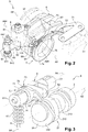
Fig. 2 is a perspective view of the valve actuation system ofFig. 1 , showing a rocker, a lever and a piston pertaining to said system; -
Fig. 3 is a partial perspective view of the engine arrangement ofFig. 1 , further showing a camshaft; -
Fig. 4 and 5 are side views of the valve actuation system ofFig. 2 , the lever being in two different positions; -
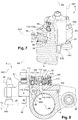
Fig. 6 is a sectional view of the valve actuation system showing a fluid circuit for moving the piston; -
Fig. 7 is another sectional view of the valve actuation system showing said fluid circuit and a reset circuit; -
Fig. 8 and9 are sectional views of the valve actuation system showing two operating configurations of the fluid circuit and reset circuit; -
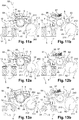
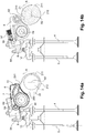
Fig. 10a to 15b schematically show the engine arrangement during various phases of the engine cycle; -
Fig. 16 is a diagram showing the evolution of the lifts of the inlet and exhaust valves of the engine arrangement during one engine cycle. - As this is illustrated in
figures 1 to 3 , the invention relates to an engine arrangement 1 of a non-represented automotive vehicle. - The engine arrangement 1 comprises a
cylinder head 3 of an internal combustion engine of the vehicle, on whichcylinder head 3 is secured abracket 31 for mounting a valve actuation system S, i.e. acamshaft 2. Thecylinder head 3 includesopenings 32 for receiving the valves of the engine. In this embodiment, each cylinder of the engine is equipped with two inlet valves (not shown), and twoexhaust valves inner exhaust valve 4 and anouter exhaust valve 5. The valves have respective axes A4, A5. -
Valves respective springs 41 and 51 (not shown onfigure 1 , but visible onfigures 3 and10a , for example). Eachvalve valves Valves figures 1 and3 , only their respective stems being visible. - The engine arrangement 1 also comprises the
camshaft 2 having an axis A2, saidcamshaft 2 being rotatably mounted around its axis A2 in anopening 33 of thebracket 31. On thecamshaft 2 are fastened cams for moving the cylinder valves, among which onecam 21 dedicated to move theexhaust valves cam 21 includes amain bump 210 and at least one auxiliary bump having a smaller radial dimension than themain bump 210. The bumps are valve lift sectors where the cam profile exhibits a bigger eccentricity with respect to axis A2 than the base radius of thecam 21. In the disclosed embodiment, thecam 21 comprises twoauxiliary bumps 211, 212 (seefigure 10b ). Besides, areset cam 26 including at least onebump 260 is also fastened on thecamshaft 2. Thereset cam 26 is offset with respect tocam 21 along axis A2. - With reference to
figure 1 , longitudinal axis X is defined as being parallel to axis A2 of the camshaft, vertical axis Z as being parallel to axes A4, A5 of thevalves - The valve actuation system S comprises a
rocker 6 which is pivotably mounted around a pivot axis A6 and alever 7 which is also pivotably mounted around a pivot axis. In the depicted embodiment, therocker 6 and thelever 7 are pivotably mounted around one and the same pivot axis A6, although their pivoting movements are different. More specifically, arocker shaft 61 is rotatably mounted around its axis A6 on thebracket 31. Therocker 6 is secured to therocker arm shaft 61 whereas thelever 7 is able to rotate around therocker arm shaft 61. A shown onfigure 2 and 3 , thelever 7 is mounted adjacent a side face of therocker 6 along axis A6. - The
rocker 6 comprises a drivenend portion 62 adapted to cooperate with thecam 21, i.e. to follow the peripheral face of saidcam 21. The drivenend portion 62 can comprise a roller. - The
rocker 6 also comprises anactuating end portion 63 located opposite the drivenend portion 62 relative to axis A6. As a result, when the drivenend portion 62 contacts a bump of thecam 21, therocker 6 is pivoted such that the drivenend portion 62 is moved away from axis A2, substantially along axis Z, and theactuating end portion 63 is moved substantially along axis Z in the opposite direction. The actuatingend portion 63 comprises a fixedactivation member 64 and a slidingpiston 8. - The
activation member 64, best shown infigure 6 , has an axis A64 parallel to the valve axes A4, A5. Theactivation member 64 comprises arod 641 the position of which, along Z, can be adjusted relative therocker 6 by means of an adjustingscrew 642. However, in operation, theactivation member 64 is fixedly mounted on therocker 6. The free end ofrod 641 facing thecylinder block 3 is equipped with apad 643 through a ball joint coupling. Theactivation member 64 is adapted to cooperate with avalve bridge 12 which cooperates with bothvalves valves end portion 62 of therocker 6 with the cammain bump 210. Thevalve bridge 12 forms a valve opening actuator, and extends substantially perpendicularly to axes A4 and A5. - The
piston 8 has an axis A8 parallel to the valve axes A4, A5. Thepiston 8 is housed in achamber 81 of therocker 6, and can slide inside saidchamber 81 along axis A8. Thepiston 8 comprises amember 82 protruding towards thecylinder block 3. In the depicted embodiment, the piston axis A8 is aligned with the inner valve axis A4. An openingmember 40 secured to thevalve 4 is slidably engaged in ahole 13 arranged in thevalve bridge 12. The openingmember 40 is operable by thepiston 8, so that thepiston 8 is able to open only theinner valve 4, following the cooperation of the drivenend portion 62 of therocker 6 with a bump of thecam 21, as will be explained later. More specifically, as it will be explained below in more detail, thepiston 8 is slidably mounted relative therocker 6, insidechamber 81, between: - a retracted position (
figure 9 ), in which a gap g1 is provided between thepiston 8 and the openingmember 40 ofvalve 4, thus preventing thepiston 8 to open thevalve 4 when the drivenend portion 62 of therocker 6 contacts anauxiliary bump figures 10b ,11b, 12b, 13b ,14b ,15b ); - and an extended position (
figures 8 ,10a ), in which gap g1 is reduced to g2, i.e. the end ofpiston 8 has come closer to the openingmember 40 ofvalve 4, thus allowing saidpiston 8 to openvalve 4 when the drivenend portion 62 contacts anauxiliary bump cam 21. In an embodiment, thepiston 8 allows activating an engine brake function when it is in its extended position. - The
rocker 6 comprises a fluid circuit for providing a fluid, such as pressurized oil, tochamber 81, in order to cause thepiston 8 to move from its retracted position to its extended position. The fluid circuit is internally arranged inrocker 6. - In the shown embodiment,
rocker shaft 61 is hollow and defines a duct 611 (figure 3 ) which is connected to a non-shown fluid tank, and to thechamber 81housing piston 8, via a check valve 97 (figure 6 ). When the engine switches to engine brake mode,check valve 97 is opened so that fluid can flow fromduct 611 to the inside ofrocker 6 and subsequently to thechamber 81 so as to induce a pressure raise and causepiston 8 to be moved towards its extended position. - The fluid circuit comprises a
main duct 103 which is connected to theduct 611 insiderocker shaft 61 via an inlet duct 102 (figure 8 ), and which fluidly links check-valve 97 with thechamber 81.Main duct 103 opens on the outside ofrocker 6 and fluid is prevented from going out ofrocker 6 by ashutter element 105 screwed into a threaded portion ofmain duct 103. The main duct successively comprises an enlarged portion 114 (figure 6 ), anintermediate portion 116, and anoutlet portion 118 opening in thecamber 81. - A
seat element 107 is press-fitted intomain duct 103, inintermediate portion 116. Aball 109 of check-valve 97 is adapted to cooperate withseat element 107 so as to block passage of fluid frompiston chamber 81 back toduct 611, and thus maintainpiston 8 in its extended position when thepiston 8 is pushing the openingmember 40.Ball 109 is biased towardsseat element 107 by aspring 111 arranged in theoutlet portion 118, and therefore tends to close the check-valve 97. When no control pressure comes fromduct 611,ball 109 is kept in open position by aplunger 110 spring-biased by aspring 112 arranged in theenlarged portion 114, the action of thespring 112 being superior to the action ofspring 111. Theinlet duct 102 is connected to theenlarged portion 114, in an area calledchamber 113 which is located on the side of theplunger 110 opposite thespring 112. In other words, fluid coming fromduct 611 first flows intochamber 113. - The
rocker 6 also comprises a reset circuit for draining the fluid out of thechamber 81 of fluid circuit to allow thepiston 8 to move towards its retracted position. The reset circuit comprises a by-pass duct 115 (figures 6 to 9 ) which originates frommain duct 103, more specifically from theoutlet portion 118 ofmain duct 103, i.e. between theball 109 and thechamber 81, and which opens on the outside ofrocker 6, to therocker shaft 61. In the by-pass duct 115 is arranged areset valve 99 which is mounted relative to therocker 6. Thus, an upstream portion 115a of the by-pass duct 115 is defined between themain duct 103 and thereset valve 99, and a downstream portion 115b of the by-pass duct 115 is defined between thereset valve 99 and the outside ofrocker 6. - The
reset valve 99 is distinct from thecheck valve 97, and is adapted to rotate around its axis A99 which is parallel to axis A6. Thereset valve 99 comprises aninside passage 98 for allowing fluid communication between the upstream portion 115a and the downstream portion 115b of the by-pass duct 115. Thus, resetvalve 99 is rotatably mounted relative to therocker 6 between an inactive position (figure 8 ), in which themain duct 103 and the downstream portion 115b of the by-pass duct 115 are not in fluid communication, and an active position (figure 9 ) in which thereset valve 99 opens the by-pass duct 115 so that the fluid can be drained out of the fluid circuit. Theinside passage 98 can be a hollow sector, as shown onfigure 8 for example, or can comprise two orthogonal bores, as shown onfigures 10b ,11b, 12b, 13b . Other implementations can be envisaged. - The
lever 7 has a drivenend portion 72 adapted to cooperate with thereset cam 26, i.e. to follow the peripheral face of saidcam 26. In an embodiment, the drivenend portion 72 comprises a leg which protrudes substantially radially away from the pivot axis A6, the free end of saidleg 72 being adapted to be in contact with thereset cam 26. - The
lever 7 also comprises anactuating end portion 73 for rotating thereset valve 99 from its inactive position towards its active position following the cooperation of the lever drivenend portion 72 with thebump 260 of thereset cam 26. In the depicted embodiment, thelever 7 comprises a ring-shapedportion 74 engaged around therocker shaft 61, and from which protrudes theleg 72. The ring-shapedportion 74 has a cylindrical outer surface on which is provided theactuating end portion 73. More specifically, in an embodiment, said cylindrical outer surface is provided withteeth 75 extending parallel to axis A6. - An
elastic member 71, such as represented infigure 2 , or anelastic member 11 , such as represented infigure 1 , may be provided to ensure the drivenend portion 72 is maintained in contact with thereset cam 26. In an embodiment, as shown infigure 2 , theelastic member 71 can be configured as a leaf having one portion fastened to theleg 72 oflever 7 and one portion secured to thebracket 31. In an alternative, as shown infigure 1 , theelastic member 11 can be configured as a latch pushing apin 77 of thelever 7, wherein thepin 77 extends in parallel to the axis A6 and extends from the ring-shapedportion 74. - Moreover, the
reset valve 99 comprises a rod 91 (figure 7 ) which protrudes outside therocker 6 towards thelever 7, parallel to axisA6. Said rod 91 is provided withteeth 95 extending parallel to axis A6. Theteeth 75 of thelever 7 and theteeth 95 of thereset valve 99 form rotational coupling means between thelever 7 and thereset valve 99. - Thus, when the
leg 72 is in contact with thereset cam 26, not on thebump 260, thelever 7 is in the position shown onfigure 4 , and thereset valve 99 is in the inactive position shown onfigure 8 . When theleg 72 is in contact with thebump 260 of thereset cam 26, thelever 7 has pivoted around axis A6 to the position shown onfigure 5 . - Consequently, via the rotational coupling means, the
lever 7 has caused thereset valve 99 to rotate towards its active position shown onfigure 9 . - The rotational coupling means are configured to provide a transmission ratio greater than 1. To ensure an adequate operation of the valve actuation system S in a limited space, the transmission ratio can range from 2 to 15, preferably from 3.6 to 9, said transmission ratio being for example around 5.5.
- For example, the valve actuation system S can be dimensioned as follows:
- radial distance between axis A6 and A99: around 35 mm;
- pitch radius of
rod 91 with teeth 95: around 5.5 mm; - pitch radius of ring-shaped
portion 74 oflever 7, with teeth 75: around 30 mm; - gear module: around 1.2.
- In an embodiment, a 10° rotation of
lever 7 can lead to a 54° rotation of thereset valve 99, which corresponds to a transmission ratio of 5.4. The maximum rotation of thelever 7 can be around 15°. - With the above described arrangement, on each turn of camshaft 2:
- cooperation between the
main bump 210 ofcam 21 and drivenend portion 62 ofroller 6, on the one hand, and betweenactivation member 64 andvalve bridge 12, on the other hand, generate opening ofvalves - when the engine brake mode is activated, i.e. when the exhaust pipe has been closed by a flap manifold (not represented) located in the exhaust pipe downstream from the turbine of the turbocharger and when the
piston 8 has been moved by pressurized fluid towards its extended position, cooperation between theauxiliary bumps cam 21 and drivenend portion 62 ofroller 6, on the one hand, and betweenpiston 8 and openingmember 40 ofvalve 4, on the other hand, generate additional and limited openings ofvalve 4 only, so as to perform an engine brake function at two precise moments during operation of engine; - cooperation between the
bump 260 ofreset cam 26 and drivenend portion 72 of thelever 7, on the one hand, and betweenteeth 75 of thelever 7 andteeth 95 of thereset valve 99, on the other hand, causes opening of the check valve and consequently draining of the fluid circuit, i.e. movement of thepiston 8 back to its retracted position. - The
dedicated reset cam 26 is adapted to create a relative movement of thelever 7, and thus of thereset valve 99, with respect to thecorresponding rocker 6. This relative movement is nevertheless coordinated with the movement of therocker 6 with respect to the engine housing, so that the reset function is performed at a selected given time within the opening/closing cycle of thevalves - When the engine brake function is not activated (
figure 9 ),check valve 97 is in opened position, due to action of the springbiased plunger 110, andpiston 8 is retracted inchamber 81. A gap g1 is provided betweenmember 82 ofpiston 2 and the openingmember 40 ofvalve 4. The drivenend portion 62 is in contact with the peripheral face of saidcam 21. When the drivenend portion 62 comes in contact with one of theauxiliary bump cam 21, therocker 6 pivoting movement is not sufficient, because of gap g1, to makemember 82 come in contact with openingmember 40. The valve opening movement thus only results from the cooperation ofactivation member 64 andvalve bridge 12, following the contact between therocker 6 and themain bump 210 ofcam 21. - The way the invention operates when the engine brake mode is activated, on each turn of
camshaft 2, will be described with reference tofigures 10a-15b which show the valve actuation system S at various moments of the engine cycle.Figures 10a ,11a, 12a, 13a ,14a ,15a show the position of thelever 7 cooperating withreset cam 26, whilefigures 10b ,11b, 12b, 13b ,14b ,15b show the position of therocker 6 cooperating withcam 21 at the respective corresponding moments. - On
figures 10a and 10b , theroller 62 ofrocker 6 is in contact with the base radius portion ofcam 21, and theleg 72 oflever 7 is in contact with the base radius portion ofreset cam 26. Aspiston 8 has moved towards its extended position, because the engine brake mode has been activated, gap g1 is reduced to g2, which is lower than the gap g3 provided between theactivation member 64 and thevalve bridge 12.Piston 8 is thus ready to cooperate with openingmember 40 to openvalve 4 whenroller 62 comes into contact with oneauxiliary bump Reset valve 99 is inactive. -
Camshaft 2,cam 21 and resetcam 26 rotate together around axis A2 according to arrow R shown onfigures 10a-15b . - In the phase illustrated on
figures 11a and 11b , theroller 62 is in contact with oneauxiliary bump 211 ofcam 21. As a result,rocker 6 pivots andpiston 8pushes opening member 40, causingvalve 4 to be slightly opened, to perform an engine brake function. Checkvalve 97 is closed. Gap g3 has been reduced but a clearance still exists, meaning thatactivation member 64 andvalve bridge 12 do not cooperate. Thelever 7 has not pivoted asleg 72 is still in contact with the base radius portion ofreset cam 26. Therefore, resetvalve 99 is still in its inactive position. - When the
roller 62 has passedauxiliary bump 211 it is in contact with the base radius portion ofcam 21. Checkvalve 97 re-opens. - As rotation of
camshaft 2 continues, theroller 62 can come in contact with a furtherauxiliary bump 212 of cam 21 (this phase not being illustrated). - In the position shown in
figures 13a and 13b , asroller 62 ofrocker 6 comes in contact with themain bump 210 ofcam 21, it is pivoted according to a greater range, causingactivation member 64 to push thevalve bridge 12, and to fully open bothvalves Springs valve 97 is closed. - As shown on
figures 14a and 14b , while theroller 62 is progressively coming back in contact with the base radius portion ofcam 21,leg 72 oflever 7 remains in contact with thebump 260 ofreset cam 26. Indeed, thebump 260 has angular range that angularly extends beyond themain bump 210 ofcam 21 and up to acorner 261 of thebump 260. It results from this difference that therocker 6 rotates with respect to thelever 7, in other words an angular offset is created between therocker 6 and thelever 7, causing thereset valve 99 to begin to rotate, in function of the pre-determined transmission ratio between thelever 7 and thereset valve 99, around axis A99, towards its active position. - The
reset valve 99 begins to open whereas thecheck valve 97 is still closed and thereset valve 99 reaches its active position, preferably before theroller 62 ofrocker 6 comes in contact with the base radius portion ofcam 21. As soon as thereset valve 99 begins to open, the fluid circuit starts being drained through the by-pass duct 115 andpiston 8 moves back to its retracted position. - Finally, as shown on
figures 15a and 15b , thereset valve 99 and the by-pass duct 115 are still opened, but theleg 72 is progressively coming back in contact with the base radius portion ofreset cam 26 reducing the angular offset between therocker 6 and thelever 7. Thereset valve 99 is thus rotated towards its inactive position and thepiston 8 is moved towards its extended position by fluid pressure inside the fluid circuit. The valve actuation system is then ready for another cycle. -
Figure 16 shows the valve lifts as a function of the camshaft rotation, namely: - the inlet valve lift;
- the outer exhaust lift (valve 5);
- the inner exhaust lift (valve 4).
- CP1 is the cam position corresponding to auxiliary bump 211: owing to the slight opening of
valve 4, more air is added in the cylinder chamber at the beginning of the compression phase. CP2 is the cam position corresponding to auxiliary bump 212: owing to the slight opening ofvalve 4, air is decompressed out of the cylinder chamber in the decompression phase, just before the top dead centre (TDC). - Owing to the
lever 7 and its specific movement as previously described, thereset valve 99 allows closing theinner exhaust valve 4 at the same time as theouter exhaust valve 5, i.e. causes an asymmetric movement profile ofvalve 4. As a result, overlap O is reduced as schematically illustrated by arrow O onfigure 15 . Reducing overlap, i.e. the time period when both the intake and exhaust valves are open, allows improving the engine brake effect. - It is to be understood that the present invention is not limited to the embodiments described above and illustrated in the drawings; rather, the skilled person will recognize that many changes and modifications may be made within the scope of the appended claims.
Claims (12)
- A valve actuation system (S) for an internal combustion engine, said valve actuation system (S) comprising:• a rocker (6) pivotably mounted around a pivot axis (A6) and having:- a driven end portion (62) adapted to cooperate with a rotating cam (21) including a main bump (210) and at least one auxiliary bump (211, 212) having a smaller radial dimension than the main bump (210);- an actuating end portion (63) equipped with at least one piston (8) adapted to open at least one valve (4) of the engine following the cooperation of the driven end portion (62) with a bump (210) of the cam (21), the piston (8) being slidably mounted relative to the rocker (6) between an extended position allowing said piston (8) to open said valve (4) when the driven end portion (62) contacts the auxiliary bump (211, 212), and a retracted position preventing said piston (8) to open said valve when the driven end portion (62) contacts the auxiliary bump (211, 212);the rocker (6) comprising:- a fluid circuit for providing a fluid in order to cause the piston (8) to move from its retracted position to its extended position;- a reset circuit comprising a reset valve (99) rotatably mounted relative to the rocker (6), between an inactive position, and an active position in which the reset valve (99) causes the fluid to be drained out of the fluid circuit to allow the piston (8) to move towards its retracted position;• a lever (7) pivotably mounted around a pivot axis (A6), the lever (7) having a driven end portion (72) adapted to cooperate with a rotating reset cam (26) including at least one bump (260), and an actuating end portion (73) for rotating the reset valve (99) from its inactive position towards its active position following the cooperation of the lever driven end portion (72) with the bump (260) of the reset cam (26); the valve actuation system (S) being characterized in that, it comprises• rotational coupling means (75, 95) between the lever (7) and the reset valve (99), said rotational coupling means having a transmission ratio greater than 1.
- The valve actuation system according to claim 1, characterized in that the transmission ratio ranges from 2 to 15, preferably from 3.6 to 9, said transmission ratio being for example around 5.5.
- The valve actuation system according to claim 1 or claim 2, characterized in that the rocker (6) and the lever (7) are pivotably mounted around one and the same pivot axis (A6).
- The valve actuation system according to claim 3, characterized in that the reset valve (99) is rotatably mounted about an axis (A99) which is parallel to the pivot axis (A6).
- The valve actuation system according to any one of claims 1 to 4, characterized in that the lever (7) comprises a portion (74) having a cylindrical outer surface provided with teeth (75), and in that the reset valve (99) comprises a rod (91) which protrudes outside the rocker (6) towards the lever (7) and which is provided with teeth (95), the teeth (75) of the lever (7) and the teeth (95) of the reset valve (99) forming at least part of the coupling means.
- The valve actuation system according to any one of claims 1 to 5, characterized in that the lever driven end portion comprises a leg (72) which protrudes substantially radially away from the pivot axis (A6), said leg (72) having a free end adapted to be in contact with the reset cam (26).
- The valve actuation system according to any one of claims 1 to 6, characterized in that it further comprises an activation member (64) which is fixedly mounted on the rocker actuating end portion (63) in operation, said activation member (64) being adapted to cooperate with a valve bridge (12) for simultaneously opening two valves (4, 5) of the engine following the cooperation of the driven end portion (62) with the cam main bump (210).
- The valve actuation system according to any one of claims 1 to 7, characterized in that it is an exhaust valve actuation system.
- The valve actuation system according to claim 8, characterized in that the piston (8) allows activating an engine brake function when it is in its extended position.
- An engine arrangement (1) comprising• a valve actuation system (S) according to any one of claims 1 to 9;• a rocker shaft (61) having a pivot axis (A61), the rocker (6) of the valve actuation system (S), and preferably the lever (7), being pivotably mounted on said rocker shaft (61);• a camshaft (2) on which are secured a reset cam (26) including at least one bump (260), and a cam (21) including a main bump (210) and at least one auxiliary bump (211, 212) having a smaller radial dimension than the main bump (210), the rocker (6) and the lever (7) being adapted for cooperating with the cam (21) and the reset cam (26), respectively;• two valves (4, 5), the piston (8) which is slidably mounted relative to the rocker (6) being adapted to open at least one of said valves (4, 5).
- The engine arrangement according to claim 10, with a valve actuation system (S) according to claim 7, characterized in that the engine arrangement (1) further comprises a valve bridge (12) moveable by the activation member (64) for simultaneously opening the two valves (4, 5), wherein the valve bridge (12) comprises a hole (13) through which is slidably engaged an opening member (40) secured to the valve (4), and operable by the piston (8), so that the piston (8) is able to open only one valve (4).
- A vehicle, characterized in that it comprises a valve actuation system (S) according to any one of claims 1 to 9 or an engine arrangement (1) according to claim 10 or 11.
Applications Claiming Priority (1)
| Application Number | Priority Date | Filing Date | Title |
|---|---|---|---|
| PCT/EP2017/084262 WO2019120556A1 (en) | 2017-12-21 | 2017-12-21 | A valve actuation system for an internal combustion engine |
Publications (2)
| Publication Number | Publication Date |
|---|---|
| EP3728803A1 EP3728803A1 (en) | 2020-10-28 |
| EP3728803B1 true EP3728803B1 (en) | 2021-08-11 |
Family
ID=60953847
Family Applications (1)
| Application Number | Title | Priority Date | Filing Date |
|---|---|---|---|
| EP17826515.3A Active EP3728803B1 (en) | 2017-12-21 | 2017-12-21 | A valve actuation system for an internal combustion engine |
Country Status (4)
| Country | Link |
|---|---|
| US (1) | US11156132B2 (en) |
| EP (1) | EP3728803B1 (en) |
| CN (1) | CN111295500B (en) |
| WO (1) | WO2019120556A1 (en) |
Families Citing this family (9)
| Publication number | Priority date | Publication date | Assignee | Title |
|---|---|---|---|---|
| CN111691942B (en) * | 2020-06-29 | 2021-05-11 | 东风商用车有限公司 | Integrated braking rocker arm device of engine |
| AT524194B1 (en) * | 2020-08-24 | 2022-12-15 | Avl List Gmbh | valve actuator |
| SE545489C2 (en) | 2020-12-18 | 2023-09-26 | Gnutti Carlo Sweden Ab | Rocker arm valve mechanism |
| CN113931712B (en) * | 2021-09-30 | 2023-06-02 | 东风商用车有限公司 | Rocker arm assembly with variable valve lift |
| DE112023001588T5 (en) * | 2022-03-28 | 2025-01-09 | Eaton Intelligent Power Limited | DOUBLE PRESSURE CAPSULE ASSEMBLY |
| WO2024199717A1 (en) * | 2023-03-31 | 2024-10-03 | Eaton Intelligent Power Limited | Rocker arm assemblies for engine braking |
| SE547384C2 (en) * | 2023-05-23 | 2025-07-29 | Gnutti Carlo Sweden Ab | A hydraulic rocker arm for a combustion engine |
| US20250179947A1 (en) * | 2023-11-30 | 2025-06-05 | Jacobs Vehicle Systems, Inc. | Integrated rocker brake with reset plunger for actuating a single engine valve |
| CN118375501B (en) * | 2024-04-30 | 2024-10-29 | 江苏卓联精密机械有限公司 | Engine rocker arm braking device and engine |
Family Cites Families (8)
| Publication number | Priority date | Publication date | Assignee | Title |
|---|---|---|---|---|
| US6253730B1 (en) * | 2000-01-14 | 2001-07-03 | Cummins Engine Company, Inc. | Engine compression braking system with integral rocker lever and reset valve |
| EP1395737A2 (en) * | 2001-06-13 | 2004-03-10 | Diesel Engine Retarders, Inc. | Latched reset mechanism for engine brake |
| US7823553B2 (en) * | 2007-03-16 | 2010-11-02 | Jacobs Vehicle Systems, Inc. | Engine brake having an articulated rocker arm and a rocker shaft mounted housing |
| US7712449B1 (en) * | 2009-05-06 | 2010-05-11 | Jacobs Vehicle Systems, Inc. | Lost motion variable valve actuation system for engine braking and early exhaust opening |
| US9163566B2 (en) * | 2011-07-06 | 2015-10-20 | Volvo Trucks AB | Valve actuation mechanism and automotive vehicle comprising such a valve actuation mechanism |
| CN204961000U (en) * | 2012-09-24 | 2016-01-13 | 雅各布斯车辆系统公司 | Integrated lost motion rocker arm brake system with automatic reset |
| CN105899770B (en) * | 2013-11-25 | 2019-06-18 | Pac制动公司 | Compression release engine braking system for idle rocker arm assembly and method of operation |
| US10907514B2 (en) * | 2016-06-25 | 2021-02-02 | Eaton Intelligent Power Limited | Valve train assembly |
-
2017
- 2017-12-21 WO PCT/EP2017/084262 patent/WO2019120556A1/en not_active Ceased
- 2017-12-21 CN CN201780096418.9A patent/CN111295500B/en active Active
- 2017-12-21 US US16/956,380 patent/US11156132B2/en active Active
- 2017-12-21 EP EP17826515.3A patent/EP3728803B1/en active Active
Also Published As
| Publication number | Publication date |
|---|---|
| WO2019120556A1 (en) | 2019-06-27 |
| CN111295500B (en) | 2022-05-03 |
| EP3728803A1 (en) | 2020-10-28 |
| US11156132B2 (en) | 2021-10-26 |
| US20210108542A1 (en) | 2021-04-15 |
| CN111295500A (en) | 2020-06-16 |
Similar Documents
| Publication | Publication Date | Title |
|---|---|---|
| US11156132B2 (en) | Valve actuation system for an internal combustion engine | |
| EP3430246B1 (en) | A device for controlling at least one valve in an internal combustion engine | |
| EP2729670B1 (en) | Valve actuation mechanism and automotive vehicle comprising such a valve actuation | |
| US7140336B2 (en) | Internal combustion engine with valves with variable actuation which are driven by a single pumping piston and controlled by a single solenoid valve for each engine cylinder | |
| CN102414424B (en) | Lost motion variable valve actuation system for engine braking and early exhaust opening | |
| EP2734713B1 (en) | Valve actuation mechanism and automotive vehicle comprising such a valve actuation mechanism | |
| EP2734715B1 (en) | Valve actuation mechanism and automotive vehicle comprising such a valve actuation mechanism | |
| EP2462323B1 (en) | Lost motion variable valve actuation system with valve catch piston | |
| WO2015017057A1 (en) | Engine brake lash adjuster device and method | |
| WO2006121181A1 (en) | Variable valve-operating device | |
| JP2007523289A (en) | Exhaust valve mechanism for internal combustion engine | |
| EP2734714B1 (en) | Valve actuation mechanism and automotive vehicle comprising such a valve actuation mechanism | |
| US7140333B2 (en) | Apparatus for an internal combustion engine | |
| JP4639130B2 (en) | INTERNAL COMBUSTION ENGINE HAVING HYDRAULIC OPERATING UNIT FOR CONTROLLING VALVE BY ROCKING OPERATION | |
| US6591802B1 (en) | Variable valve actuating mechanism having a rotary hydraulic lash adjuster | |
| US20250172077A1 (en) | Control system for a decompression engine brake | |
| CN118805018A (en) | Hydraulic capsule for variable valve actuation |
Legal Events
| Date | Code | Title | Description |
|---|---|---|---|
| STAA | Information on the status of an ep patent application or granted ep patent |
Free format text: STATUS: UNKNOWN |
|
| STAA | Information on the status of an ep patent application or granted ep patent |
Free format text: STATUS: THE INTERNATIONAL PUBLICATION HAS BEEN MADE |
|
| PUAI | Public reference made under article 153(3) epc to a published international application that has entered the european phase |
Free format text: ORIGINAL CODE: 0009012 |
|
| STAA | Information on the status of an ep patent application or granted ep patent |
Free format text: STATUS: REQUEST FOR EXAMINATION WAS MADE |
|
| 17P | Request for examination filed |
Effective date: 20200326 |
|
| AK | Designated contracting states |
Kind code of ref document: A1 Designated state(s): AL AT BE BG CH CY CZ DE DK EE ES FI FR GB GR HR HU IE IS IT LI LT LU LV MC MK MT NL NO PL PT RO RS SE SI SK SM TR |
|
| AX | Request for extension of the european patent |
Extension state: BA ME |
|
| DAV | Request for validation of the european patent (deleted) | ||
| DAX | Request for extension of the european patent (deleted) | ||
| GRAP | Despatch of communication of intention to grant a patent |
Free format text: ORIGINAL CODE: EPIDOSNIGR1 |
|
| STAA | Information on the status of an ep patent application or granted ep patent |
Free format text: STATUS: GRANT OF PATENT IS INTENDED |
|
| INTG | Intention to grant announced |
Effective date: 20210514 |
|
| GRAS | Grant fee paid |
Free format text: ORIGINAL CODE: EPIDOSNIGR3 |
|
| GRAA | (expected) grant |
Free format text: ORIGINAL CODE: 0009210 |
|
| STAA | Information on the status of an ep patent application or granted ep patent |
Free format text: STATUS: THE PATENT HAS BEEN GRANTED |
|
| AK | Designated contracting states |
Kind code of ref document: B1 Designated state(s): AL AT BE BG CH CY CZ DE DK EE ES FI FR GB GR HR HU IE IS IT LI LT LU LV MC MK MT NL NO PL PT RO RS SE SI SK SM TR |
|
| REG | Reference to a national code |
Ref country code: CH Ref legal event code: EP |
|
| REG | Reference to a national code |
Ref country code: DE Ref legal event code: R096 Ref document number: 602017043974 Country of ref document: DE |
|
| REG | Reference to a national code |
Ref country code: IE Ref legal event code: FG4D Ref country code: AT Ref legal event code: REF Ref document number: 1419599 Country of ref document: AT Kind code of ref document: T Effective date: 20210915 |
|
| REG | Reference to a national code |
Ref country code: LT Ref legal event code: MG9D |
|
| REG | Reference to a national code |
Ref country code: NL Ref legal event code: MP Effective date: 20210811 |
|
| REG | Reference to a national code |
Ref country code: AT Ref legal event code: MK05 Ref document number: 1419599 Country of ref document: AT Kind code of ref document: T Effective date: 20210811 |
|
| PG25 | Lapsed in a contracting state [announced via postgrant information from national office to epo] |
Ref country code: RS Free format text: LAPSE BECAUSE OF FAILURE TO SUBMIT A TRANSLATION OF THE DESCRIPTION OR TO PAY THE FEE WITHIN THE PRESCRIBED TIME-LIMIT Effective date: 20210811 Ref country code: SE Free format text: LAPSE BECAUSE OF FAILURE TO SUBMIT A TRANSLATION OF THE DESCRIPTION OR TO PAY THE FEE WITHIN THE PRESCRIBED TIME-LIMIT Effective date: 20210811 Ref country code: HR Free format text: LAPSE BECAUSE OF FAILURE TO SUBMIT A TRANSLATION OF THE DESCRIPTION OR TO PAY THE FEE WITHIN THE PRESCRIBED TIME-LIMIT Effective date: 20210811 Ref country code: FI Free format text: LAPSE BECAUSE OF FAILURE TO SUBMIT A TRANSLATION OF THE DESCRIPTION OR TO PAY THE FEE WITHIN THE PRESCRIBED TIME-LIMIT Effective date: 20210811 Ref country code: ES Free format text: LAPSE BECAUSE OF FAILURE TO SUBMIT A TRANSLATION OF THE DESCRIPTION OR TO PAY THE FEE WITHIN THE PRESCRIBED TIME-LIMIT Effective date: 20210811 Ref country code: BG Free format text: LAPSE BECAUSE OF FAILURE TO SUBMIT A TRANSLATION OF THE DESCRIPTION OR TO PAY THE FEE WITHIN THE PRESCRIBED TIME-LIMIT Effective date: 20211111 Ref country code: AT Free format text: LAPSE BECAUSE OF FAILURE TO SUBMIT A TRANSLATION OF THE DESCRIPTION OR TO PAY THE FEE WITHIN THE PRESCRIBED TIME-LIMIT Effective date: 20210811 Ref country code: LT Free format text: LAPSE BECAUSE OF FAILURE TO SUBMIT A TRANSLATION OF THE DESCRIPTION OR TO PAY THE FEE WITHIN THE PRESCRIBED TIME-LIMIT Effective date: 20210811 Ref country code: NO Free format text: LAPSE BECAUSE OF FAILURE TO SUBMIT A TRANSLATION OF THE DESCRIPTION OR TO PAY THE FEE WITHIN THE PRESCRIBED TIME-LIMIT Effective date: 20211111 Ref country code: PT Free format text: LAPSE BECAUSE OF FAILURE TO SUBMIT A TRANSLATION OF THE DESCRIPTION OR TO PAY THE FEE WITHIN THE PRESCRIBED TIME-LIMIT Effective date: 20211213 |
|
| PG25 | Lapsed in a contracting state [announced via postgrant information from national office to epo] |
Ref country code: PL Free format text: LAPSE BECAUSE OF FAILURE TO SUBMIT A TRANSLATION OF THE DESCRIPTION OR TO PAY THE FEE WITHIN THE PRESCRIBED TIME-LIMIT Effective date: 20210811 Ref country code: LV Free format text: LAPSE BECAUSE OF FAILURE TO SUBMIT A TRANSLATION OF THE DESCRIPTION OR TO PAY THE FEE WITHIN THE PRESCRIBED TIME-LIMIT Effective date: 20210811 Ref country code: GR Free format text: LAPSE BECAUSE OF FAILURE TO SUBMIT A TRANSLATION OF THE DESCRIPTION OR TO PAY THE FEE WITHIN THE PRESCRIBED TIME-LIMIT Effective date: 20211112 |
|
| PG25 | Lapsed in a contracting state [announced via postgrant information from national office to epo] |
Ref country code: NL Free format text: LAPSE BECAUSE OF FAILURE TO SUBMIT A TRANSLATION OF THE DESCRIPTION OR TO PAY THE FEE WITHIN THE PRESCRIBED TIME-LIMIT Effective date: 20210811 |
|
| PG25 | Lapsed in a contracting state [announced via postgrant information from national office to epo] |
Ref country code: DK Free format text: LAPSE BECAUSE OF FAILURE TO SUBMIT A TRANSLATION OF THE DESCRIPTION OR TO PAY THE FEE WITHIN THE PRESCRIBED TIME-LIMIT Effective date: 20210811 |
|
| REG | Reference to a national code |
Ref country code: DE Ref legal event code: R097 Ref document number: 602017043974 Country of ref document: DE |
|
| PG25 | Lapsed in a contracting state [announced via postgrant information from national office to epo] |
Ref country code: SM Free format text: LAPSE BECAUSE OF FAILURE TO SUBMIT A TRANSLATION OF THE DESCRIPTION OR TO PAY THE FEE WITHIN THE PRESCRIBED TIME-LIMIT Effective date: 20210811 Ref country code: SK Free format text: LAPSE BECAUSE OF FAILURE TO SUBMIT A TRANSLATION OF THE DESCRIPTION OR TO PAY THE FEE WITHIN THE PRESCRIBED TIME-LIMIT Effective date: 20210811 Ref country code: RO Free format text: LAPSE BECAUSE OF FAILURE TO SUBMIT A TRANSLATION OF THE DESCRIPTION OR TO PAY THE FEE WITHIN THE PRESCRIBED TIME-LIMIT Effective date: 20210811 Ref country code: EE Free format text: LAPSE BECAUSE OF FAILURE TO SUBMIT A TRANSLATION OF THE DESCRIPTION OR TO PAY THE FEE WITHIN THE PRESCRIBED TIME-LIMIT Effective date: 20210811 Ref country code: CZ Free format text: LAPSE BECAUSE OF FAILURE TO SUBMIT A TRANSLATION OF THE DESCRIPTION OR TO PAY THE FEE WITHIN THE PRESCRIBED TIME-LIMIT Effective date: 20210811 Ref country code: AL Free format text: LAPSE BECAUSE OF FAILURE TO SUBMIT A TRANSLATION OF THE DESCRIPTION OR TO PAY THE FEE WITHIN THE PRESCRIBED TIME-LIMIT Effective date: 20210811 |
|
| PLBE | No opposition filed within time limit |
Free format text: ORIGINAL CODE: 0009261 |
|
| STAA | Information on the status of an ep patent application or granted ep patent |
Free format text: STATUS: NO OPPOSITION FILED WITHIN TIME LIMIT |
|
| 26N | No opposition filed |
Effective date: 20220512 |
|
| PG25 | Lapsed in a contracting state [announced via postgrant information from national office to epo] |
Ref country code: MC Free format text: LAPSE BECAUSE OF FAILURE TO SUBMIT A TRANSLATION OF THE DESCRIPTION OR TO PAY THE FEE WITHIN THE PRESCRIBED TIME-LIMIT Effective date: 20210811 Ref country code: IT Free format text: LAPSE BECAUSE OF FAILURE TO SUBMIT A TRANSLATION OF THE DESCRIPTION OR TO PAY THE FEE WITHIN THE PRESCRIBED TIME-LIMIT Effective date: 20210811 |
|
| REG | Reference to a national code |
Ref country code: CH Ref legal event code: PL |
|
| GBPC | Gb: european patent ceased through non-payment of renewal fee |
Effective date: 20211221 |
|
| REG | Reference to a national code |
Ref country code: BE Ref legal event code: MM Effective date: 20211231 |
|
| PG25 | Lapsed in a contracting state [announced via postgrant information from national office to epo] |
Ref country code: LU Free format text: LAPSE BECAUSE OF NON-PAYMENT OF DUE FEES Effective date: 20211221 Ref country code: IE Free format text: LAPSE BECAUSE OF NON-PAYMENT OF DUE FEES Effective date: 20211221 Ref country code: GB Free format text: LAPSE BECAUSE OF NON-PAYMENT OF DUE FEES Effective date: 20211221 |
|
| PG25 | Lapsed in a contracting state [announced via postgrant information from national office to epo] |
Ref country code: BE Free format text: LAPSE BECAUSE OF NON-PAYMENT OF DUE FEES Effective date: 20211231 |
|
| PG25 | Lapsed in a contracting state [announced via postgrant information from national office to epo] |
Ref country code: LI Free format text: LAPSE BECAUSE OF NON-PAYMENT OF DUE FEES Effective date: 20211231 Ref country code: CH Free format text: LAPSE BECAUSE OF NON-PAYMENT OF DUE FEES Effective date: 20211231 |
|
| PG25 | Lapsed in a contracting state [announced via postgrant information from national office to epo] |
Ref country code: CY Free format text: LAPSE BECAUSE OF FAILURE TO SUBMIT A TRANSLATION OF THE DESCRIPTION OR TO PAY THE FEE WITHIN THE PRESCRIBED TIME-LIMIT Effective date: 20210811 |
|
| PG25 | Lapsed in a contracting state [announced via postgrant information from national office to epo] |
Ref country code: HU Free format text: LAPSE BECAUSE OF FAILURE TO SUBMIT A TRANSLATION OF THE DESCRIPTION OR TO PAY THE FEE WITHIN THE PRESCRIBED TIME-LIMIT; INVALID AB INITIO Effective date: 20171221 |
|
| PG25 | Lapsed in a contracting state [announced via postgrant information from national office to epo] |
Ref country code: SI Free format text: LAPSE BECAUSE OF FAILURE TO SUBMIT A TRANSLATION OF THE DESCRIPTION OR TO PAY THE FEE WITHIN THE PRESCRIBED TIME-LIMIT Effective date: 20210811 |
|
| PG25 | Lapsed in a contracting state [announced via postgrant information from national office to epo] |
Ref country code: MK Free format text: LAPSE BECAUSE OF FAILURE TO SUBMIT A TRANSLATION OF THE DESCRIPTION OR TO PAY THE FEE WITHIN THE PRESCRIBED TIME-LIMIT Effective date: 20210811 |
|
| PG25 | Lapsed in a contracting state [announced via postgrant information from national office to epo] |
Ref country code: TR Free format text: LAPSE BECAUSE OF FAILURE TO SUBMIT A TRANSLATION OF THE DESCRIPTION OR TO PAY THE FEE WITHIN THE PRESCRIBED TIME-LIMIT Effective date: 20210811 |
|
| PG25 | Lapsed in a contracting state [announced via postgrant information from national office to epo] |
Ref country code: MT Free format text: LAPSE BECAUSE OF FAILURE TO SUBMIT A TRANSLATION OF THE DESCRIPTION OR TO PAY THE FEE WITHIN THE PRESCRIBED TIME-LIMIT Effective date: 20210811 |
|
| PGFP | Annual fee paid to national office [announced via postgrant information from national office to epo] |
Ref country code: FR Payment date: 20241227 Year of fee payment: 8 |
|
| PGFP | Annual fee paid to national office [announced via postgrant information from national office to epo] |
Ref country code: DE Payment date: 20251229 Year of fee payment: 9 |