EP3728012B1 - System for transferring cryogenic product between two ships placed side by side - Google Patents
System for transferring cryogenic product between two ships placed side by side Download PDFInfo
- Publication number
- EP3728012B1 EP3728012B1 EP18826373.5A EP18826373A EP3728012B1 EP 3728012 B1 EP3728012 B1 EP 3728012B1 EP 18826373 A EP18826373 A EP 18826373A EP 3728012 B1 EP3728012 B1 EP 3728012B1
- Authority
- EP
- European Patent Office
- Prior art keywords
- pipe
- transfer pipe
- connection
- transfer
- cryogenic
- Prior art date
- Legal status (The legal status is an assumption and is not a legal conclusion. Google has not performed a legal analysis and makes no representation as to the accuracy of the status listed.)
- Active
Links
Images



Classifications
-
- B—PERFORMING OPERATIONS; TRANSPORTING
- B63—SHIPS OR OTHER WATERBORNE VESSELS; RELATED EQUIPMENT
- B63B—SHIPS OR OTHER WATERBORNE VESSELS; EQUIPMENT FOR SHIPPING
- B63B27/00—Arrangement of ship-based loading or unloading equipment for cargo or passengers
- B63B27/30—Arrangement of ship-based loading or unloading equipment for transfer at sea between ships or between ships and off-shore structures
- B63B27/34—Arrangement of ship-based loading or unloading equipment for transfer at sea between ships or between ships and off-shore structures using pipe-lines
-
- B—PERFORMING OPERATIONS; TRANSPORTING
- B63—SHIPS OR OTHER WATERBORNE VESSELS; RELATED EQUIPMENT
- B63B—SHIPS OR OTHER WATERBORNE VESSELS; EQUIPMENT FOR SHIPPING
- B63B27/00—Arrangement of ship-based loading or unloading equipment for cargo or passengers
- B63B27/24—Arrangement of ship-based loading or unloading equipment for cargo or passengers of pipe-lines
-
- B—PERFORMING OPERATIONS; TRANSPORTING
- B63—SHIPS OR OTHER WATERBORNE VESSELS; RELATED EQUIPMENT
- B63B—SHIPS OR OTHER WATERBORNE VESSELS; EQUIPMENT FOR SHIPPING
- B63B73/00—Building or assembling vessels or marine structures, e.g. hulls or offshore platforms
- B63B73/20—Building or assembling prefabricated vessel modules or parts other than hull blocks, e.g. engine rooms, rudders, propellers, superstructures, berths, holds or tanks
-
- B—PERFORMING OPERATIONS; TRANSPORTING
- B67—OPENING, CLOSING OR CLEANING BOTTLES, JARS OR SIMILAR CONTAINERS; LIQUID HANDLING
- B67D—DISPENSING, DELIVERING OR TRANSFERRING LIQUIDS, NOT OTHERWISE PROVIDED FOR
- B67D9/00—Apparatus or devices for transferring liquids when loading or unloading ships
- B67D9/02—Apparatus or devices for transferring liquids when loading or unloading ships using articulated pipes
-
- F—MECHANICAL ENGINEERING; LIGHTING; HEATING; WEAPONS; BLASTING
- F16—ENGINEERING ELEMENTS AND UNITS; GENERAL MEASURES FOR PRODUCING AND MAINTAINING EFFECTIVE FUNCTIONING OF MACHINES OR INSTALLATIONS; THERMAL INSULATION IN GENERAL
- F16L—PIPES; JOINTS OR FITTINGS FOR PIPES; SUPPORTS FOR PIPES, CABLES OR PROTECTIVE TUBING; MEANS FOR THERMAL INSULATION IN GENERAL
- F16L23/00—Flanged joints
- F16L23/003—Auxiliary devices
-
- F—MECHANICAL ENGINEERING; LIGHTING; HEATING; WEAPONS; BLASTING
- F17—STORING OR DISTRIBUTING GASES OR LIQUIDS
- F17C—VESSELS FOR CONTAINING OR STORING COMPRESSED, LIQUEFIED OR SOLIDIFIED GASES; FIXED-CAPACITY GAS-HOLDERS; FILLING VESSELS WITH, OR DISCHARGING FROM VESSELS, COMPRESSED, LIQUEFIED, OR SOLIDIFIED GASES
- F17C2205/00—Vessel construction, in particular mounting arrangements, attachments or identifications means
- F17C2205/03—Fluid connections, filters, valves, closure means or other attachments
- F17C2205/0302—Fittings, valves, filters, or components in connection with the gas storage device
- F17C2205/0352—Pipes
- F17C2205/0364—Pipes flexible or articulated, e.g. a hose
-
- F—MECHANICAL ENGINEERING; LIGHTING; HEATING; WEAPONS; BLASTING
- F17—STORING OR DISTRIBUTING GASES OR LIQUIDS
- F17C—VESSELS FOR CONTAINING OR STORING COMPRESSED, LIQUEFIED OR SOLIDIFIED GASES; FIXED-CAPACITY GAS-HOLDERS; FILLING VESSELS WITH, OR DISCHARGING FROM VESSELS, COMPRESSED, LIQUEFIED, OR SOLIDIFIED GASES
- F17C2221/00—Handled fluid, in particular type of fluid
- F17C2221/01—Pure fluids
- F17C2221/014—Nitrogen
-
- F—MECHANICAL ENGINEERING; LIGHTING; HEATING; WEAPONS; BLASTING
- F17—STORING OR DISTRIBUTING GASES OR LIQUIDS
- F17C—VESSELS FOR CONTAINING OR STORING COMPRESSED, LIQUEFIED OR SOLIDIFIED GASES; FIXED-CAPACITY GAS-HOLDERS; FILLING VESSELS WITH, OR DISCHARGING FROM VESSELS, COMPRESSED, LIQUEFIED, OR SOLIDIFIED GASES
- F17C2223/00—Handled fluid before transfer, i.e. state of fluid when stored in the vessel or before transfer from the vessel
- F17C2223/01—Handled fluid before transfer, i.e. state of fluid when stored in the vessel or before transfer from the vessel characterised by the phase
- F17C2223/0146—Two-phase
- F17C2223/0153—Liquefied gas, e.g. LPG, GPL
- F17C2223/0161—Liquefied gas, e.g. LPG, GPL cryogenic, e.g. LNG, GNL, PLNG
-
- F—MECHANICAL ENGINEERING; LIGHTING; HEATING; WEAPONS; BLASTING
- F17—STORING OR DISTRIBUTING GASES OR LIQUIDS
- F17C—VESSELS FOR CONTAINING OR STORING COMPRESSED, LIQUEFIED OR SOLIDIFIED GASES; FIXED-CAPACITY GAS-HOLDERS; FILLING VESSELS WITH, OR DISCHARGING FROM VESSELS, COMPRESSED, LIQUEFIED, OR SOLIDIFIED GASES
- F17C2270/00—Applications
- F17C2270/01—Applications for fluid transport or storage
- F17C2270/0102—Applications for fluid transport or storage on or in the water
-
- F—MECHANICAL ENGINEERING; LIGHTING; HEATING; WEAPONS; BLASTING
- F17—STORING OR DISTRIBUTING GASES OR LIQUIDS
- F17C—VESSELS FOR CONTAINING OR STORING COMPRESSED, LIQUEFIED OR SOLIDIFIED GASES; FIXED-CAPACITY GAS-HOLDERS; FILLING VESSELS WITH, OR DISCHARGING FROM VESSELS, COMPRESSED, LIQUEFIED, OR SOLIDIFIED GASES
- F17C2270/00—Applications
- F17C2270/01—Applications for fluid transport or storage
- F17C2270/0102—Applications for fluid transport or storage on or in the water
- F17C2270/0105—Ships
Definitions
- the invention relates to a system for transferring cryogenic products between two structures placed side by side during the transfer, the first structure being a floating structure for storage and transport of cryogenic product, such as a methane tanker (referred to below as "LNGC”) and the second structure being a fixed or floating (freely or moored) structure such as a methane tanker converted into a terminal for reception and storage of cryogenic products, of FSRU type (FSRU standing for Floating Storage and Regasification Unit).
- the cryogenic product may, without being limitative, be liquefied gas, such as liquefied natural gas (referred to below as "LNG”), liquid ethane, or liquid ethylene.
- a first known solution is a transfer system comprising at least one flexible pipe.
- this type of transfer system has a very limited range of movement. More particularly, this transfer arm comprises flexible pipes.
- flexible pipes must not be bent beyond a certain limit in order not to be damaged.
- the rate of flow is limited by high losses in pressure from the flexible pipes, in particular on the vapor return line in which the pressure losses must be minimal.
- This solution is also very constraining, in particular because it requires the use of a crane throughout the time of transfer of a cryogenic product between for example an LNGC and an FSRU.
- the present invention is directed to providing a system for the transfer of cryogenic product from a first floating structure for storage and transport of cryogenic product to a second fixed or floating structure for storing cryogenic product placed side by side and not having the drawbacks mentioned above and furthermore leading to other advantages.
- the present invention concerns a floating structure for storage and transport of cryogenic product, as defined in claim 1.
- the present invention concerns a method of fluidically connecting a system for transferring cryogenic product, as defined in claim 8.
- Figure 1 represents a diagrammatic side view of a short-chain transfer system for the transfer of cryogenic product from a first floating structure 800 for storage of cryogenic product (here a LNGC) to a second fixed or floating structure 900 for storing cryogenic product (here an FSRU), comprising a transfer pipe formed from rigid sections of pipe configured for transporting the cryogenic product between an extension pipe 18 linked to the first structure 800 and an extension pipe 11 linked to the second structure 900, the sections of pipe being fluidically connected each to the next by connection means 21 to 27 able to transport the cryogenic product.
- a first floating structure 800 for storage of cryogenic product here a LNGC
- FSRU cryogenic product
- a extension pipe 11 is linked at one of its ends to the second structure by a collecting device 910 and at its other end to a section of transfer pipe by two bolted couplings 46.
- a bent portion 12 is linked by a cryogenic swivel joint 21 to a transfer pipe tip 12' bearing the linking coupling to a coupling of the extension pipe 11 (cf. the pair of couplings 46 in Figure 1 ).
- the cryogenic joint 21 has its horizontal main axis in the plane of the drawing paper. Thus, this structure enables rotation of the transfer system in a vertical plane.
- the bent portion 12 is linked to the rest of the transfer system by an ERS 30, which latter will be described later.
- the ERS comprises in particular a lower part 32 linked to a section of pipe of half-circular general shape.
- the half-circle section of pipe comprises two bent sections abutted so as to form a half-circle.
- the upper part of the half-circle section of pipe is linked to the lower part 32 of the ERS by a cryogenic swivel joint 22 and at its other end by a cryogenic swivel joint 23 to a bent section of pipe 13.
- the cryogenic swivel joint 22 has its vertical main axis in the plane of the drawing paper and enables a rotation around the main axis of the ERS 30.
- the cryogenic swivel joint 23 has its horizontal main axis in a plane perpendicular to the drawing paper and enables a movement in the plane of the drawing paper.
- the specific arrangement of the three cryogenic swivel joints 21 to 23 makes it possible to obtain movements in three dimensions of the system for transfer between two structures.
- bent section of pipe 13 is linked to the bent section of pipe 14 by a cryogenic swivel joint 24 of which the horizontal main axis is perpendicular to the plane of the drawing paper.
- the bent section of pipe 14 is linked to the bent section of pipe 15 by a cryogenic swivel joint 25 of which the horizontal main axis is also perpendicular to the plane of the drawing paper.
- the bent section of pipe 15 is linked to the bent section of pipe 16 by a cryogenic swivel joint 26 of which the horizontal main axis is also perpendicular to the plane of the drawing paper.
- bent section of pipe 16 is linked to the extension pipe 18 by three abutted bent sections immobile relative to each other.
- the bent section of pipe 16 is linked to the bent section of pipe 17 via a section comprising three bent sections abutted so as to form a half-circle terminated by a section bent at 90° to its upper part.
- the lower part of the half-circle section is linked to the bent section of pipe 16 by a cryogenic swivel joint 27.
- the upper part of the section is immobile relative to the bent section of pipe 17.
- the cryogenic swivel joint 27 has its horizontal main axis in a plane perpendicular to the drawing paper and enables a movement in the plane of the drawing paper.
- the upper part of the bent section of pipe 17 is linked to the extension pipe 18 via a cryogenic swivel joint 28, a bent portion, a second cryogenic swivel joint 29 and a coupling tip forming with the coupling of the extension pipe 18 a pair of couplings 45.
- the cryogenic swivel joint 28 has its vertical main axis in the plane of the drawing paper and enables a rotation around the main axis of the bent section of pipe 17.
- the cryogenic joint 29 has its horizontal main axis in the plane of the drawing paper. Thus, this structure enables rotation of the transfer arm in a vertical plane.
- the short chain part 100 of the transfer pipe is constituted here by the sections of pipe 13 to 16 linked each to the next and to the rest of the structure by cryogenic swivel joints 23 to 27.
- the number of such sections of pipe may in practice be reduced to three or be greater than four.
- each metal bent portion is disposed at least one reinforcing collar making it possible to avoid flattening of the metal bent portion under the effect of high loads.
- the reinforcing collar is constituted by a metal circle welded to the periphery of the bent portion.
- the arrangements of the axes and planes as mentioned supra correspond in practice to those of the structures 800 and 900 when they are placed side by side without being either inclined or offset longitudinally relative to each other.
- each extension pipe towards the edge of the structure and its connection coupling form a connection device for the transfer pipe.
- connection means are cryogenic swivel joints here with a rotational axis.
- connection means may be envisaged to use flexible sections of pipe.
- the extension pipe 11, on the second floating structure 900, is carried by a support 950 and linked to a device for storage of cryogenic product (not shown in Figure 1 ) by a collecting device 910.
- the extension pipe 18 is carried at the first floating structure 800 by a support mounting 850 making it possible to take up part of the bending stresses to which a collecting device 810 of the floating structure 800 is subjected when the transfer system is connected via the extension pipe 18.
- the two extension pipes 11,18 are linked to the transfer system by bolted couplings 45, 46 making it possible to provide the cryogenic link of the transfer system.
- one of the couplings of each pair of couplings may be replaced by a coupler.
- a transfer system provides the transfer of the useful cryogenic fluid, that is to say the liquefied gas.
- a second transfer system of the same type provides the return of cold vapor (which is cryogenic in practice) in parallel with the transfer of cryogenic fluid.
- the short chain transfer system comprises a self-supporting short chain 100.
- no hoisting device is required during the phase of transferring cryogenic fluid.
- bent it is meant that the sections are bent at their end or that bent portions are welded to the ends of straight sections.
- the four bent sections of pipe 13 to 16 are linked together each to the next by three cryogenic joints 24 to 26.
- the short chain 100 is next linked to the extension pipes 11, 18 via the section of pipe 17, bent portions and connection means 21-23 and 27-29.
- an Emergency Release System 30 commonly called ERS system, is disposed at the bent portion 12.
- the Emergency Release System 30 could be disposed at another section of pipe such as the section of pipe 17 linked to the extension pipe 18 on the first floating structure 800.
- the ERS 30 comprises two parts: an upper part 31 linked to the bent portion 12 and a lower part 32 linked to the connection means 22. In case of emergency stoppage, the two parts of the ERS 30 detach.
- the lower part 32 is kept from free fall by a cable - not shown - linked to a winch 33 disposed on the deck 920 of the second floating structure 900.
- the winch makes it possible to control the fall of the short chain 100 towards its position of vertical equilibrium along the hull of the LNGC 800.
- Bumpers 47- 50, here of neoprene, disposed on the short chain (at the location of the connection means) enable the hull to be protected.
- the cable is not fastened to the winch drum and is naturally released from the drum at the end of unreeling.
- the extension pipe 11 is linked here to the moored or floating structure 900 via a support mounting 950 comprising two vertical rigid arms 951 linked at one end of the deck of the second floating structure 900 and at a second end to a cross-bar 952 for supporting the extension pipe 11.
- connection pipe 850 In the embodiment represented in Figures 3A and 3B , a support mounting for the connection pipe 850 is represented.
- the support 850 represented here, comprises a rectangular base 513 on which rest two substantially vertical beams 514. These beams bear a horizontal beam 515 on which is placed, here, a shim 512.
- the bearing of the extension pipe 18 is made via a roller 516.
- the support mounting 850 makes it possible to reduce the stresses on the collecting device 810 when the transfer system is connected.
- the support 850 is furthermore provided to allow for the thermal shrinkage of the extension pipe 18.
- the support mounting can comprise lateral stops 511 to take up the lateral loads of the short chain 100. In the normal way, these loads are small and do not generate excessive bending moment on the collecting device 810.
- the support mounting 850 forms part of the extension pipe 18 and the space enabling the shim to be fitted is located between the deck 820 of first floating structure 820 and the base 513 of the support mounting 850.
- the linkage system 40 makes it possible to facilitate the connection between the extension pipe 18 and the section of pipe 17 at the time of the connection phase.
- the maintenance time is in particular optimized.
- the linkage system 40 comprises two parts cooperating with each other: a male part 41 linked to the section 17 and a female part 42 linked to the extension pipe 18.
- the female part 42 comprises an upwardly open cut-out 421, which is hook-shaped here, and configured receive the male part 41 forming the complementary part and comprising for such purpose a ring-shaped part 411 (here two parallel lugs fastened to the section 17, between which extends a rod, perpendicularly to the lugs).
- This linkage system has the advantage of guiding the end of the transfer system but also of keeping the ends linked when the hoisting device, enabling the connection to be established, is no longer used.
- the transfer system is already linked to the floating structure 900 by the section of pipe 17 and is held in elevation at its other end above the level of the pipe 11 by means of a hoisting device, such as a crane, by a ring 90 or an equivalent hitching means for a hook of a hoisting device.
- a hoisting device such as a crane
- a ring 90 or an equivalent hitching means for a hook of a hoisting device.
- the pipe 18 linked to the collecting device on the floating structure 800 comprises a two-way valve 91 enabling the cryogenic liquid to be stopped or allowed to be conveyed to the second floating structure 900.
- the extension pipe 11 linked to the collecting device of the second floating structure 900 also comprises a two-way valve 92 enabling the cryogenic liquid to be stopped or allowed to be conveyed to the storage device - not shown -.
- the extension pipe 11 is linked to a nitrogen supply pipe 19 linked to a pressurized nitrogen network enabling nitrogen to be forcefully inlet into part of the extension pipe 11 of the second floating structure 900 and into the transfer system.
- the nitrogen supply pipe 19 also comprises a two-way valve 92 enabling the nitrogen to be stopped or allowed to pass into the fluid transfer system.
- cryogenic fluid transfer valves 91, 92 are open and the nitrogen supply valve 93 is closed.
- the cryogenic liquid can flow between the two floating structures 800, 900.
- the transfer pipe can also include, at the LNGC, one (or two) manual valves enabling isolation of the pipe and the disconnection of the pipe 18 with residual cryogenic liquid which will be evaporated on storage.
- a method of storing the transfer arm is represented in different steps.
- the transfer system is transported onto a standard container platform by means of a hoisting device.
- the linking means between the hoisting device and the transfer device comprises a rigid beam 82 enabling the transfer system to be raised using the connection means 21, 29.
- connection means 25 When the transfer system is laid on the container platform 200, the connection means 25 is the first to enter into contact with the container platform 200. Next, the connection means 24, 26 are connected to cables 83, 84 by an operator. The cables 83, 84 enable an acute angle to be formed, by pulling on the connection means 24, 26, between the rigid sections of pipes 15,16 and between the rigid sections of pipe 13, 14.
- the hoisting system In a same phase or after having disposed the sections of pipe so as to form an acute angle, the hoisting system lowers the transfer system in order for the sections of pipe 14,15 to rest on the container platform.
- the cables 83, 84 which maintain the acute angle are detached.
- the hoisting system lowers the transfer system for the sections of pipe 13, 16 to lie on the container platform.
- the cables 85, 86 are then detached.
- the hoisting bar 82 is detached from the transfer arm at the end of the maneuver.
- posts 103, 106 for supporting the sections of pipe are provided on the container platform.
- the transfer arm occupies the place of a container of standard size.
- the transfer arm does not encumber the hull of a floating structure and is not stowed on a hoisting device, such as a crane.
- the temporary storage of the transfer pipe can also be made along the hull of the FSRU by rotation of the transfer pipe through 90° around the "vertical" axis of the connection means 22.
- the section of pipe 17 is then locked on a mounting at the location of the platform of the FSRU
Landscapes
- Engineering & Computer Science (AREA)
- Mechanical Engineering (AREA)
- Chemical & Material Sciences (AREA)
- Combustion & Propulsion (AREA)
- Ocean & Marine Engineering (AREA)
- General Engineering & Computer Science (AREA)
- Architecture (AREA)
- Structural Engineering (AREA)
- Filling Or Discharging Of Gas Storage Vessels (AREA)
- Loading And Unloading Of Fuel Tanks Or Ships (AREA)
- Thermal Insulation (AREA)
Description
- The invention relates to a system for transferring cryogenic products between two structures placed side by side during the transfer, the first structure being a floating structure for storage and transport of cryogenic product, such as a methane tanker (referred to below as "LNGC") and the second structure being a fixed or floating (freely or moored) structure such as a methane tanker converted into a terminal for reception and storage of cryogenic products, of FSRU type (FSRU standing for Floating Storage and Regasification Unit). The cryogenic product may, without being limitative, be liquefied gas, such as liquefied natural gas (referred to below as "LNG"), liquid ethane, or liquid ethylene.
- A first known solution is a transfer system comprising at least one flexible pipe. However, this type of transfer system has a very limited range of movement. More particularly, this transfer arm comprises flexible pipes. However, flexible pipes must not be bent beyond a certain limit in order not to be damaged. Furthermore, the rate of flow is limited by high losses in pressure from the flexible pipes, in particular on the vapor return line in which the pressure losses must be minimal.
- A second solution is described in patent application
WO 99/48752 - This solution is also very constraining, in particular because it requires the use of a crane throughout the time of transfer of a cryogenic product between for example an LNGC and an FSRU.
- The present invention is directed to providing a system for the transfer of cryogenic product from a first floating structure for storage and transport of cryogenic product to a second fixed or floating structure for storing cryogenic product placed side by side and not having the drawbacks mentioned above and furthermore leading to other advantages.
- To that end, according to a first aspect the present invention concerns a floating structure for storage and transport of cryogenic product, as defined in claim 1.
- Such a solution has numerous advantages and in particular those of fast implementation and avoids the permanent use of a hoisting device dedicated to the transfer of fluid.
- According to other possible features, taken in isolation or in combination one with another:
- at least one of the connection means comprises a cryogenic swivel joint connected to each of the ends of two successive sections of pipe by at least one bent tube or to a bent end of each of the two successive sections of pipe;
- the transfer pipe comprises a short chain comprising five cryogenic swivel joints having an axis disposed in the vertical plane and linking four sections of rigid pipe each to the next, and the short chain is adapted to be linked to each of the connection devices for the structures by a rigid tubular assembly for connection of the transfer pipe and on each of which is interposed a set of two cryogenic swivel joints having an axis arranged with the swivel joints for linking to the short chain so as to provide with them three degrees of rotational freedom;
- the transfer pipe extends freely as a short chain over part of its length between the connection devices of the first and second floating structures at the time of transferring cryogenic product;
- at least one of the end sections of pipe of the transfer pipe comprises a hooking means for hooking to hoisting means;
- the connection device for the first structure comprises a centering part having an upwardly open cut-out configured to guide a complementary part of a tip of the transfer pipe towards a connection position of the tip situated at the bottom of the cut-out;
- the system comprises a device for storage of the transfer pipe in folded state, comprising a vertical support erected on the base of the device for each free end of the transfer pipe, so as to be able to dispose the transfer pipe in a configuration folded in the storage device into a trapezoidal shape.
- According to a second aspect the present invention concerns a method of fluidically connecting a system for transferring cryogenic product, as defined in claim 8.
- Still other particularities and advantages of the invention will appear in the following description of non-limiting examples, made with reference to the accompanying drawings, in which:
-
Figure 1 is a diagrammatic side view of a device in accordance with an embodiment of the invention; -
Figure 2 is a detail side view according to an embodiment of the invention in particular representing the support mounting of the free end of the extension pipe; -
Figure 3A is a detail side view of the support mounting of the system on the first floating structure according to an embodiment; -
Figure 3B is a detail view of the link between the support mounting in relation with the LNGC and the extension pipe according to an embodiment of the invention; -
Figure 4A is a detail side view of a locked transfer system according to an embodiment of the invention; -
Figure 4B is a detail side view of the centering part of the guiding and holding system according to an embodiment of the invention; -
Figure 4C is a detail side view of the complementary part of the guiding and holding system according to an embodiment of the invention; -
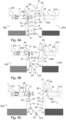
Figure 5A is a side view of a device in course of connection according to an embodiment of the invention; -
Figure 5B is a side view of a device before connection according to an embodiment of the invention; -
Figure 5C is a side view of a connected device according to an embodiment of the invention; -
Figure 6A is a very diagrammatic side view representation of a device and of the main valves necessary for purging the device; -
Figure 6B is a very diagrammatic side view representation of a connected device on passage of nitrogen within the sections of pipe for purging the device; -
Figure 6C is a very diagrammatic side view representation of a connected device on disconnection of the device; -
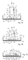
Figures 7A and 7B are two very diagrammatic side view representations of a device according to an embodiment in phase of loading onto a container platform; -
Figure 7C is a side view of a device according to an embodiment in final phase of loading onto a platform. -
Figure 1 represents a diagrammatic side view of a short-chain transfer system for the transfer of cryogenic product from a firstfloating structure 800 for storage of cryogenic product (here a LNGC) to a second fixed orfloating structure 900 for storing cryogenic product (here an FSRU), comprising a transfer pipe formed from rigid sections of pipe configured for transporting the cryogenic product between anextension pipe 18 linked to thefirst structure 800 and anextension pipe 11 linked to thesecond structure 900, the sections of pipe being fluidically connected each to the next by connection means 21 to 27 able to transport the cryogenic product. - A
extension pipe 11 is linked at one of its ends to the second structure by acollecting device 910 and at its other end to a section of transfer pipe by two boltedcouplings 46. - A
bent portion 12 is linked by acryogenic swivel joint 21 to a transfer pipe tip 12' bearing the linking coupling to a coupling of the extension pipe 11 (cf. the pair ofcouplings 46 inFigure 1 ). - The
cryogenic joint 21 has its horizontal main axis in the plane of the drawing paper. Thus, this structure enables rotation of the transfer system in a vertical plane. - The
bent portion 12 is linked to the rest of the transfer system by anERS 30, which latter will be described later. - The ERS comprises in particular a
lower part 32 linked to a section of pipe of half-circular general shape. - The half-circle section of pipe comprises two bent sections abutted so as to form a half-circle. The upper part of the half-circle section of pipe is linked to the
lower part 32 of the ERS by a cryogenicswivel joint 22 and at its other end by a cryogenicswivel joint 23 to a bent section ofpipe 13. - The
cryogenic swivel joint 22 has its vertical main axis in the plane of the drawing paper and enables a rotation around the main axis of theERS 30. - The
cryogenic swivel joint 23 has its horizontal main axis in a plane perpendicular to the drawing paper and enables a movement in the plane of the drawing paper. - Thus, the specific arrangement of the three
cryogenic swivel joints 21 to 23 makes it possible to obtain movements in three dimensions of the system for transfer between two structures. - Next there are represented four bent sections of
pipe 13 to 16 linked to each other by a cryogenicswivel joint 24 to 26. - In other words, the bent section of
pipe 13 is linked to the bent section ofpipe 14 by a cryogenicswivel joint 24 of which the horizontal main axis is perpendicular to the plane of the drawing paper. - The bent section of
pipe 14 is linked to the bent section ofpipe 15 by a cryogenicswivel joint 25 of which the horizontal main axis is also perpendicular to the plane of the drawing paper. - The bent section of
pipe 15 is linked to the bent section ofpipe 16 by a cryogenicswivel joint 26 of which the horizontal main axis is also perpendicular to the plane of the drawing paper. - The bent section of
pipe 16 is linked to theextension pipe 18 by three abutted bent sections immobile relative to each other. - In other words, the bent section of
pipe 16 is linked to the bent section ofpipe 17 via a section comprising three bent sections abutted so as to form a half-circle terminated by a section bent at 90° to its upper part. The lower part of the half-circle section is linked to the bent section ofpipe 16 by a cryogenicswivel joint 27. The upper part of the section is immobile relative to the bent section ofpipe 17. - The
cryogenic swivel joint 27 has its horizontal main axis in a plane perpendicular to the drawing paper and enables a movement in the plane of the drawing paper. - The upper part of the bent section of
pipe 17 is linked to theextension pipe 18 via a cryogenicswivel joint 28, a bent portion, a second cryogenicswivel joint 29 and a coupling tip forming with the coupling of the extension pipe 18 a pair ofcouplings 45. - The
cryogenic swivel joint 28 has its vertical main axis in the plane of the drawing paper and enables a rotation around the main axis of the bent section ofpipe 17. - The
cryogenic joint 29 has its horizontal main axis in the plane of the drawing paper. Thus, this structure enables rotation of the transfer arm in a vertical plane. - Furthermore, the
short chain part 100 of the transfer pipe is constituted here by the sections ofpipe 13 to 16 linked each to the next and to the rest of the structure bycryogenic swivel joints 23 to 27. The number of such sections of pipe may in practice be reduced to three or be greater than four. - At the location of each metal bent portion is disposed at least one reinforcing collar making it possible to avoid flattening of the metal bent portion under the effect of high loads. In the embodiment represented in
Figure 1 , the reinforcing collar is constituted by a metal circle welded to the periphery of the bent portion. - It will be noted in this connection that a section of pipe may in practice be represented just by a bent portion.
- Moreover, the arrangements of the axes and planes as mentioned supra correspond in practice to those of the
structures - It will furthermore be noted that each extension pipe towards the edge of the structure and its connection coupling form a connection device for the transfer pipe.
- The connection means are cryogenic swivel joints here with a rotational axis. As a variant, it may be envisaged to use flexible sections of pipe.
- Furthermore, each pipe or section of
pipe 11 to 18 here is of uniform construction, of preferably between 6 and 20 inches (1 inch = 2.54 cm). However, as a variant, they may be variable. - The
extension pipe 11, on the second floatingstructure 900, is carried by asupport 950 and linked to a device for storage of cryogenic product (not shown inFigure 1 ) by acollecting device 910. - The
extension pipe 18 is carried at the first floatingstructure 800 by a support mounting 850 making it possible to take up part of the bending stresses to which acollecting device 810 of the floatingstructure 800 is subjected when the transfer system is connected via theextension pipe 18. - The two
extension pipes couplings - In practice, at least two transfer systems are installed when a fluid transfer is carried out. A transfer system provides the transfer of the useful cryogenic fluid, that is to say the liquefied gas. A second transfer system of the same type provides the return of cold vapor (which is cryogenic in practice) in parallel with the transfer of cryogenic fluid.
- As can still be seen in
Figure 1 , the short chain transfer system comprises a self-supportingshort chain 100. In other words, no hoisting device is required during the phase of transferring cryogenic fluid. - As already indicated, this
short chain 100 comprises at least three rigid bent sections of pipe, here four 13, 14, 15, 16, situated in the vertical plane, able to transport cryogenic fluid. - In this case, by bent it is meant that the sections are bent at their end or that bent portions are welded to the ends of straight sections.
- The four bent sections of
pipe 13 to 16 are linked together each to the next by threecryogenic joints 24 to 26. - As also indicated supra, the
short chain 100 is next linked to theextension pipes pipe 17, bent portions and connection means 21-23 and 27-29. - In the embodiment represented in
Figure 2 , anEmergency Release System 30, commonly called ERS system, is disposed at thebent portion 12. Of course, in an alternative embodiment, theEmergency Release System 30 could be disposed at another section of pipe such as the section ofpipe 17 linked to theextension pipe 18 on the first floatingstructure 800. - The
ERS 30 comprises two parts: anupper part 31 linked to thebent portion 12 and alower part 32 linked to the connection means 22. In case of emergency stoppage, the two parts of theERS 30 detach. Thelower part 32 is kept from free fall by a cable - not shown - linked to a winch 33 disposed on thedeck 920 of the second floatingstructure 900. - The winch makes it possible to control the fall of the
short chain 100 towards its position of vertical equilibrium along the hull of theLNGC 800. Bumpers 47- 50, here of neoprene, disposed on the short chain (at the location of the connection means) enable the hull to be protected. - The cable is not fastened to the winch drum and is naturally released from the drum at the end of unreeling.
- The
extension pipe 11 is linked here to the moored or floatingstructure 900 via a support mounting 950 comprising two verticalrigid arms 951 linked at one end of the deck of the second floatingstructure 900 and at a second end to a cross-bar 952 for supporting theextension pipe 11. - In the embodiment represented in
Figures 3A and 3B , a support mounting for theconnection pipe 850 is represented. - The
support 850, represented here, comprises arectangular base 513 on which rest two substantiallyvertical beams 514. These beams bear ahorizontal beam 515 on which is placed, here, ashim 512. The bearing of theextension pipe 18 is made via aroller 516. - The support mounting 850 makes it possible to reduce the stresses on the
collecting device 810 when the transfer system is connected. - Play exists before connection of the
short chain 100. When theshort chain 100 is connected, theextension pipe 18 is bent and comes to bear on theshim 512. - This is a means for reducing the vertical load transmitted to the platform of the LNGC by acting on the
collecting device 810 to the maximum of its capacity at the time of bending. - The
support 850 is furthermore provided to allow for the thermal shrinkage of theextension pipe 18. - If required, the support mounting can comprise lateral stops 511 to take up the lateral loads of the
short chain 100. In the normal way, these loads are small and do not generate excessive bending moment on thecollecting device 810. - In one alternative embodiment, the support mounting 850 forms part of the
extension pipe 18 and the space enabling the shim to be fitted is located between thedeck 820 of first floatingstructure 820 and thebase 513 of the support mounting 850. - In the embodiment represented in
Figures 4A to 4C alinkage system 40 is represented. - The
linkage system 40 makes it possible to facilitate the connection between theextension pipe 18 and the section ofpipe 17 at the time of the connection phase. Thus, the maintenance time is in particular optimized. - More specifically, the
linkage system 40 comprises two parts cooperating with each other: amale part 41 linked to thesection 17 and afemale part 42 linked to theextension pipe 18. Thefemale part 42 comprises an upwardly open cut-out 421, which is hook-shaped here, and configured receive themale part 41 forming the complementary part and comprising for such purpose a ring-shaped part 411 (here two parallel lugs fastened to thesection 17, between which extends a rod, perpendicularly to the lugs). - When the two
parts bores 412. - This linkage system has the advantage of guiding the end of the transfer system but also of keeping the ends linked when the hoisting device, enabling the connection to be established, is no longer used.
- In the embodiment represented in
Figures 5A to 5B , a linking method is represented in different steps. - In
Figure 5A , the transfer system is already linked to the floatingstructure 900 by the section ofpipe 17 and is held in elevation at its other end above the level of thepipe 11 by means of a hoisting device, such as a crane, by aring 90 or an equivalent hitching means for a hook of a hoisting device. There are may be a second one, as a variant, on the opposite side of the transfer pipe. - When the male and
female parts Figure 5B , the transfer arm comes to a higher level than the free end of theextension pipe 18. Thus, theseparts linkage system 40 may cooperate before the transfer pipe and theextension pipe 18 are face to face for them to be bolted. - In the embodiment represented in
Figures 6A to 6B , a purging method is represented in different steps. - In
Figure 6A , thepipe 18 linked to the collecting device on the floatingstructure 800 comprises a two-way valve 91 enabling the cryogenic liquid to be stopped or allowed to be conveyed to the second floatingstructure 900. Theextension pipe 11 linked to the collecting device of the second floatingstructure 900 also comprises a two-way valve 92 enabling the cryogenic liquid to be stopped or allowed to be conveyed to the storage device - not shown -. Theextension pipe 11 is linked to anitrogen supply pipe 19 linked to a pressurized nitrogen network enabling nitrogen to be forcefully inlet into part of theextension pipe 11 of the second floatingstructure 900 and into the transfer system. Thenitrogen supply pipe 19 also comprises a two-way valve 92 enabling the nitrogen to be stopped or allowed to pass into the fluid transfer system. - When cryogenic liquid is transferred, with reference to
Figure 6A , the cryogenicfluid transfer valves nitrogen supply valve 93 is closed. Thus, the cryogenic liquid can flow between the two floatingstructures - With reference to
Figure 6B , when the transfer of cryogenic liquid has terminated, the valve of the second floatingstructure 92 is closed and the valve of the first floatingstructure 91 stays open. Thenitrogen supply valve 93 is open allowing nitrogen to pass into the transfer system. Thus, the amount of cryogenic liquid is reduced in the sections of pipe forming the transfer system. - With reference to
Figure 6C , the nitrogen supply valves and the first floatingstructure structure 92 is kept closed. Next, the transfer system is linked to a hoisting device (not shown). Then the transfer system is disconnected at the location of theextension pipe 18 of the first floating structure. The purge is then terminated. - As a variant, the transfer pipe can also include, at the LNGC, one (or two) manual valves enabling isolation of the pipe and the disconnection of the
pipe 18 with residual cryogenic liquid which will be evaporated on storage. - In the embodiment represented in
Figures 7A to 7C , a method of storing the transfer arm is represented in different steps. With reference toFigure 7A , the transfer system is transported onto a standard container platform by means of a hoisting device. The linking means between the hoisting device and the transfer device comprises arigid beam 82 enabling the transfer system to be raised using the connection means 21, 29. - When the transfer system is laid on the
container platform 200, the connection means 25 is the first to enter into contact with thecontainer platform 200. Next, the connection means 24, 26 are connected tocables cables pipes pipe - In a same phase or after having disposed the sections of pipe so as to form an acute angle, the hoisting system lowers the transfer system in order for the sections of
pipe cables -
Cables cables pipes pipe - In the same way as described above, the hoisting system lowers the transfer system for the sections of
pipe cables - The connection means 21, 29 then lie on the vertical
rigid supports - The hoisting
bar 82 is detached from the transfer arm at the end of the maneuver. - It will furthermore be observed that
posts - Thus, the transfer arm occupies the place of a container of standard size. The transfer arm does not encumber the hull of a floating structure and is not stowed on a hoisting device, such as a crane.
- The temporary storage of the transfer pipe can also be made along the hull of the FSRU by rotation of the transfer pipe through 90° around the "vertical" axis of the connection means 22. The section of
pipe 17 is then locked on a mounting at the location of the platform of the FSRU - Numerous other variants are possible according to circumstances, and in this connection it is to be noted that the present invention is not limited to the examples represented and described.
- In particular, several pipes for transfer and for return of cold vapor may be implemented.
Claims (8)
- Floating structure (800) for storage and transport of cryogenic product, comprising a system for transferring cryogenic product from the floating structure, called first floating structure (800), to a second fixed or floating structure (900) for storing cryogenic product, the system comprising a transfer pipe suitable for transporting the cryogenic product, the transfer pipe being self-supporting and comprising at least three rigid sections of pipe (12-17), fluidically connected each to the next by connection means (21-27) suitable for transporting the cryogenic product, each of the two end sections of the transfer pipe (12, 17) having a free end configured as a tip for connection to a connection device of the first floating structure (800) and respectively of the second floating structure (900);
wherein the system comprises (i) the connection device, which is intended to be disposed on the first structure (800), and comprises an extension pipe (11,18) configured to be connected to a collecting device (810, 910) of the associated first structure and to one of the tips of the transfer pipe; and (ii) a support mounting (850, 950) for the free end of the extension pipe, wherein the free end of the extension pipe is the end of the extension pipe to be connected to the transfer pipe, characterized by the support mounting being disposed on the first floating structure and an interstice being provided between the extension pipe of the first structure and its support mounting or between the support mounting and the first structure intended to carry it so as to enable predetermined bending of the extension pipe after connection of the tip of the transfer pipe to that extension pipe, the interstice closing once the transfer pipe is connected. - A system according to claim 1, characterized in that at least one of the connection means comprises a cryogenic swivel joint (21-29) connected to each of the ends of two successive sections of pipe by at least one bent tube or to a bent end of each of the two successive sections of pipe.
- A system according to one of the preceding claims, characterized in that the transfer pipe comprises a short chain (100) comprising five cryogenic swivel joints having an axis disposed in the vertical plane and linking four sections of rigid pipe each to the next, and the short chain (100) is adapted to be linked to each of the connection devices (11, 18) for the structures (800, 900) by a rigid tubular assembly for connection of the transfer pipe and on each of which is interposed a set of two cryogenic swivel joints having an axis arranged with the swivel joints for linking to the short chain so as to provide with them three degrees of rotational freedom.
- A system according to one of the preceding claims, characterized in that the transfer pipe extends freely as a short chain over part of its length between the connection devices for the first and second structures at the time of transferring cryogenic product.
- A system according to one of the preceding claims, characterized in that at least one of the end sections of pipe (12 to 17) of the transfer pipe comprises a hooking means (90) for hooking to hoisting means.
- A system according to one of the preceding claims, characterized in that the connection device (40) for the first structure comprises a centering part (42) having an upwardly open cut-out configured to guide a complementary part (41) of a tip of the transfer pipe towards a connection position of the tip situated at the bottom of the cut-out.
- A system according to claim 1, characterized in that it comprises a device for storage of the transfer pipe in folded state, comprising a vertical support erected on the base of the device for each free end of the transfer pipe, so as to be able to dispose the transfer pipe in a configuration folded in the storage device into a quadrilateral with two parallel sides shape.
- A method of fluidically connecting a system for transferring cryogenic product from a first floating structure (800) for storage and transport of cryogenic product to a second fixed or floating structure (900) for storing cryogenic product, the system comprising a rigid transfer pipe suitable for transporting the cryogenic product, the transfer pipe being self-supporting and comprising at least three sections of pipe (12-17), fluidically connected each to the next by connection means (21-27) suitable for transporting the cryogenic product, each of the two end sections of pipe having a free end configured as a tip for connection to a connection device of the first floating structure (800) and respectively of the second floating structure (900), wherein the system comprises (i) the connection devices, which are intended to be disposed respectively on the first structure (800) and the second structure (900), and comprise each an extension pipe (11,18) configured to be connected to a collecting device (810, 910) of the associated first or second structure and to one of the tips of the transfer pipe; and (ii) a support mounting (850, 950) for the free end of each extension pipe, wherein the free end of the extension pipe is the end of the extension pipe to be connected to the transfer pipe, an interstice being provided between the extension pipe of the first structure and its support mounting or between the support mounting and the first structure intended to carry it so as to enable predetermined bending of the extension pipe after connection of the tip of the transfer pipe to that extension pipe, the interstice closing once the transfer pipe is connected, and wherein the connection device (40) of the first structure comprising a centering part (42) having an upwardly open cut-out configured to guide a complementary part (41) of a tip of the transfer pipe towards a connection position of the tip situated at the bottom of the cut-out,
the method comprising the following steps:- Forming the link between the transfer pipe and the extension pipe of the connection device of the second structure;- Moving the transfer pipe above the extension pipe of the connection device of the first structure using a cable linked to a hoisting apparatus, such a crane;- Lowering the free tip of the transfer pipe towards a connection coupling of the extension pipe located on the first structure;- Hooking the free tip to the extension pipe by means of the centering part and the complementary part; and- Fastening the free tip to the connection coupling.
Applications Claiming Priority (2)
| Application Number | Priority Date | Filing Date | Title |
|---|---|---|---|
| FR1763195A FR3075755A1 (en) | 2017-12-22 | 2017-12-22 | CRYOGENIC PRODUCT TRANSFER SYSTEM BETWEEN TWO SHIPS SIDED SIDE |
| PCT/EP2018/086542 WO2019122316A1 (en) | 2017-12-22 | 2018-12-21 | System for transferring cryogenic product between two ships placed side by side |
Publications (2)
| Publication Number | Publication Date |
|---|---|
| EP3728012A1 EP3728012A1 (en) | 2020-10-28 |
| EP3728012B1 true EP3728012B1 (en) | 2025-04-23 |
Family
ID=61655954
Family Applications (1)
| Application Number | Title | Priority Date | Filing Date |
|---|---|---|---|
| EP18826373.5A Active EP3728012B1 (en) | 2017-12-22 | 2018-12-21 | System for transferring cryogenic product between two ships placed side by side |
Country Status (11)
| Country | Link |
|---|---|
| US (1) | US11667356B2 (en) |
| EP (1) | EP3728012B1 (en) |
| JP (1) | JP7275138B2 (en) |
| KR (1) | KR102639976B1 (en) |
| CN (1) | CN111372847B (en) |
| AU (1) | AU2018386560B2 (en) |
| CA (1) | CA3086774A1 (en) |
| FR (1) | FR3075755A1 (en) |
| PL (1) | PL3728012T3 (en) |
| SG (1) | SG11202003262YA (en) |
| WO (1) | WO2019122316A1 (en) |
Families Citing this family (3)
| Publication number | Priority date | Publication date | Assignee | Title |
|---|---|---|---|---|
| US11577348B2 (en) * | 2018-07-16 | 2023-02-14 | William A. Schahuber | Tank fabricating equipment |
| CN111981208A (en) * | 2020-07-09 | 2020-11-24 | 中国船舶重工集团公司第七O三研究所无锡分部 | Universal high-temperature high-pressure steam distribution device |
| CN113374970B (en) * | 2021-05-24 | 2024-06-25 | 中国能源建设集团山西省电力勘测设计院有限公司 | Flexible compensation mechanism for branch connection part of long-distance steam conveying pipeline |
Citations (3)
| Publication number | Priority date | Publication date | Assignee | Title |
|---|---|---|---|---|
| EP0947464A1 (en) * | 1998-04-01 | 1999-10-06 | Single Buoy Moorings Inc. | Fluid transfer boom with coaxial fluid ducts |
| WO2009141675A1 (en) * | 2008-05-22 | 2009-11-26 | Fmc Technologies Sa | Control device for fluid transfer system on sea |
| WO2011026951A1 (en) * | 2009-09-03 | 2011-03-10 | Single Buoy Moorings Inc. | Structural connector diverting loads away from the cool connector |
Family Cites Families (11)
| Publication number | Priority date | Publication date | Assignee | Title |
|---|---|---|---|---|
| US2648201A (en) * | 1949-09-02 | 1953-08-11 | Standard Oil Dev Co | Offshore ship unloading facilities for high-pressure fluids |
| US3050092A (en) * | 1959-06-26 | 1962-08-21 | Exxon Research Engineering Co | Marine loading arm |
| US4202372A (en) * | 1976-12-01 | 1980-05-13 | Fmc Corporation | Articulated fluid conduit with auxiliary support |
| NO981332L (en) | 1998-03-24 | 1999-09-27 | Hitec Marine As | Cold media offshore loading system |
| FR2796375B1 (en) * | 1999-07-13 | 2001-10-12 | Fmc Europe | OFFSHORE LOADING SYSTEM BY SUSPENDED PIPING |
| FR2903753B1 (en) | 2006-07-13 | 2012-01-20 | Eurodim Sa | DEVICE FOR CONNECTING THE END OF A DEFORMABLE CONDUIT FOR DELIVERING A FLUID TO A FIXED PIPING SYSTEM SUCH AS THE MANIFOLD OF A SHIP. |
| FR2927322B1 (en) * | 2008-02-08 | 2010-03-05 | Fmc Technologies Sa | DEVICE FOR DIRECT CONTROL, PARTICULARLY PROPORTIONAL AND / OR LOADING AND / OR UNLOADING FLUIDS |
| FR2941434B1 (en) * | 2009-01-27 | 2015-05-01 | Fmc Technologies Sa | SYSTEM FOR TRANSFERRING A FLUID PRODUCT AND ITS IMPLEMENTATION |
| EP2953847B1 (en) * | 2013-02-05 | 2017-11-29 | MacGregor Norway AS | Arrangements and a method for connection and disconnection of at least one hose carrying fluid especially lng and/or vaporized lng |
| NO340699B1 (en) * | 2013-02-05 | 2017-06-06 | Macgregor Norway As | Fluid transfer system and method for transferring cryogenic hydrocarbon-based fluid from a supply structure to a receiving structure |
| FR3003855B1 (en) * | 2013-03-29 | 2016-01-29 | Fmc Technologies Sa | TRANSFER ARM OF A FLUID PRODUCT FROM SHIP TO SHIP |
-
2017
- 2017-12-22 FR FR1763195A patent/FR3075755A1/en active Pending
-
2018
- 2018-12-21 WO PCT/EP2018/086542 patent/WO2019122316A1/en not_active Ceased
- 2018-12-21 CA CA3086774A patent/CA3086774A1/en active Pending
- 2018-12-21 PL PL18826373.5T patent/PL3728012T3/en unknown
- 2018-12-21 AU AU2018386560A patent/AU2018386560B2/en active Active
- 2018-12-21 CN CN201880075312.5A patent/CN111372847B/en active Active
- 2018-12-21 EP EP18826373.5A patent/EP3728012B1/en active Active
- 2018-12-21 JP JP2020534286A patent/JP7275138B2/en active Active
- 2018-12-21 KR KR1020207020821A patent/KR102639976B1/en active Active
- 2018-12-21 US US16/956,518 patent/US11667356B2/en active Active
- 2018-12-21 SG SG11202003262YA patent/SG11202003262YA/en unknown
Patent Citations (3)
| Publication number | Priority date | Publication date | Assignee | Title |
|---|---|---|---|---|
| EP0947464A1 (en) * | 1998-04-01 | 1999-10-06 | Single Buoy Moorings Inc. | Fluid transfer boom with coaxial fluid ducts |
| WO2009141675A1 (en) * | 2008-05-22 | 2009-11-26 | Fmc Technologies Sa | Control device for fluid transfer system on sea |
| WO2011026951A1 (en) * | 2009-09-03 | 2011-03-10 | Single Buoy Moorings Inc. | Structural connector diverting loads away from the cool connector |
Also Published As
| Publication number | Publication date |
|---|---|
| US11667356B2 (en) | 2023-06-06 |
| FR3075755A1 (en) | 2019-06-28 |
| CN111372847B (en) | 2022-10-04 |
| WO2019122316A1 (en) | 2019-06-27 |
| JP7275138B2 (en) | 2023-05-17 |
| KR102639976B1 (en) | 2024-02-22 |
| AU2018386560A1 (en) | 2020-05-21 |
| EP3728012A1 (en) | 2020-10-28 |
| CN111372847A (en) | 2020-07-03 |
| RU2020123935A (en) | 2022-01-24 |
| AU2018386560B2 (en) | 2025-01-23 |
| RU2020123935A3 (en) | 2022-01-24 |
| PL3728012T3 (en) | 2025-09-08 |
| US20210129946A1 (en) | 2021-05-06 |
| JP2021507847A (en) | 2021-02-25 |
| BR112020010340A2 (en) | 2020-11-10 |
| SG11202003262YA (en) | 2020-05-28 |
| CA3086774A1 (en) | 2019-06-27 |
| KR20200093675A (en) | 2020-08-05 |
Similar Documents
| Publication | Publication Date | Title |
|---|---|---|
| KR101778311B1 (en) | System for transferring a fluid product and its implementation | |
| EP2433901B1 (en) | Apparatus and method for offloading a hydrocarbon fluid | |
| US9004103B2 (en) | Apparatus and method for offloading a hydrocarbon fluid | |
| US8539970B2 (en) | Device for transferring a fluid to a ship, ship, transfer system and associated method | |
| US8864420B2 (en) | Offshore systems and methods for liquefied gas production, storage and offloading to reduce and prevent damage | |
| US11667356B2 (en) | System for transferring cryogenic product between two ships placed side by side | |
| EP3678930B1 (en) | Tie-in system and fluid transfer system comprising such a tie-in system | |
| US7299835B2 (en) | Apparatus for transferring a fluid between a transport vessel and a storage station | |
| US20240400163A1 (en) | A transfer system for transferring a medium between facilities | |
| KR20210030403A (en) | Liquefied gas delivery system | |
| RU2774086C2 (en) | System for pumping cryogenic product between two vessels placed next to each other | |
| US9302746B2 (en) | System and method for displacing an operating envelope of an offloading system in an offshore environment | |
| BR112020010340B1 (en) | SYSTEM FOR TRANSFERRING CRYOGENIC PRODUCT AND METHOD FOR FLUIDICALLY CONNECTING A SYSTEM FOR TRANSFERRING CRYOGENIC PRODUCT |
Legal Events
| Date | Code | Title | Description |
|---|---|---|---|
| STAA | Information on the status of an ep patent application or granted ep patent |
Free format text: STATUS: UNKNOWN |
|
| STAA | Information on the status of an ep patent application or granted ep patent |
Free format text: STATUS: THE INTERNATIONAL PUBLICATION HAS BEEN MADE |
|
| PUAI | Public reference made under article 153(3) epc to a published international application that has entered the european phase |
Free format text: ORIGINAL CODE: 0009012 |
|
| STAA | Information on the status of an ep patent application or granted ep patent |
Free format text: STATUS: REQUEST FOR EXAMINATION WAS MADE |
|
| 17P | Request for examination filed |
Effective date: 20200703 |
|
| AK | Designated contracting states |
Kind code of ref document: A1 Designated state(s): AL AT BE BG CH CY CZ DE DK EE ES FI FR GB GR HR HU IE IS IT LI LT LU LV MC MK MT NL NO PL PT RO RS SE SI SK SM TR |
|
| AX | Request for extension of the european patent |
Extension state: BA ME |
|
| DAV | Request for validation of the european patent (deleted) | ||
| DAX | Request for extension of the european patent (deleted) | ||
| STAA | Information on the status of an ep patent application or granted ep patent |
Free format text: STATUS: EXAMINATION IS IN PROGRESS |
|
| 17Q | First examination report despatched |
Effective date: 20221012 |
|
| P01 | Opt-out of the competence of the unified patent court (upc) registered |
Effective date: 20230601 |
|
| RAP1 | Party data changed (applicant data changed or rights of an application transferred) |
Owner name: T.EN LOADING SYSTEMS |
|
| GRAP | Despatch of communication of intention to grant a patent |
Free format text: ORIGINAL CODE: EPIDOSNIGR1 |
|
| STAA | Information on the status of an ep patent application or granted ep patent |
Free format text: STATUS: GRANT OF PATENT IS INTENDED |
|
| INTG | Intention to grant announced |
Effective date: 20241122 |
|
| RIN1 | Information on inventor provided before grant (corrected) |
Inventor name: PAQUET, STEPHANE Inventor name: POICHOT, RAPHAEL |
|
| GRAS | Grant fee paid |
Free format text: ORIGINAL CODE: EPIDOSNIGR3 |
|
| GRAA | (expected) grant |
Free format text: ORIGINAL CODE: 0009210 |
|
| STAA | Information on the status of an ep patent application or granted ep patent |
Free format text: STATUS: THE PATENT HAS BEEN GRANTED |
|
| AK | Designated contracting states |
Kind code of ref document: B1 Designated state(s): AL AT BE BG CH CY CZ DE DK EE ES FI FR GB GR HR HU IE IS IT LI LT LU LV MC MK MT NL NO PL PT RO RS SE SI SK SM TR |
|
| REG | Reference to a national code |
Ref country code: GB Ref legal event code: FG4D |
|
| REG | Reference to a national code |
Ref country code: CH Ref legal event code: EP |
|
| REG | Reference to a national code |
Ref country code: DE Ref legal event code: R096 Ref document number: 602018081363 Country of ref document: DE |
|
| REG | Reference to a national code |
Ref country code: IE Ref legal event code: FG4D |
|
| REG | Reference to a national code |
Ref country code: SE Ref legal event code: TRGR |
|
| REG | Reference to a national code |
Ref country code: NL Ref legal event code: FP |
|
| REG | Reference to a national code |
Ref country code: AT Ref legal event code: MK05 Ref document number: 1787541 Country of ref document: AT Kind code of ref document: T Effective date: 20250423 |
|
| PG25 | Lapsed in a contracting state [announced via postgrant information from national office to epo] |
Ref country code: FI Free format text: LAPSE BECAUSE OF FAILURE TO SUBMIT A TRANSLATION OF THE DESCRIPTION OR TO PAY THE FEE WITHIN THE PRESCRIBED TIME-LIMIT Effective date: 20250423 Ref country code: ES Free format text: LAPSE BECAUSE OF FAILURE TO SUBMIT A TRANSLATION OF THE DESCRIPTION OR TO PAY THE FEE WITHIN THE PRESCRIBED TIME-LIMIT Effective date: 20250423 Ref country code: PT Free format text: LAPSE BECAUSE OF FAILURE TO SUBMIT A TRANSLATION OF THE DESCRIPTION OR TO PAY THE FEE WITHIN THE PRESCRIBED TIME-LIMIT Effective date: 20250825 |
|
| REG | Reference to a national code |
Ref country code: LT Ref legal event code: MG9D |
|
| PG25 | Lapsed in a contracting state [announced via postgrant information from national office to epo] |
Ref country code: GR Free format text: LAPSE BECAUSE OF FAILURE TO SUBMIT A TRANSLATION OF THE DESCRIPTION OR TO PAY THE FEE WITHIN THE PRESCRIBED TIME-LIMIT Effective date: 20250724 |
|
| PG25 | Lapsed in a contracting state [announced via postgrant information from national office to epo] |
Ref country code: BG Free format text: LAPSE BECAUSE OF FAILURE TO SUBMIT A TRANSLATION OF THE DESCRIPTION OR TO PAY THE FEE WITHIN THE PRESCRIBED TIME-LIMIT Effective date: 20250423 |
|
| PG25 | Lapsed in a contracting state [announced via postgrant information from national office to epo] |
Ref country code: HR Free format text: LAPSE BECAUSE OF FAILURE TO SUBMIT A TRANSLATION OF THE DESCRIPTION OR TO PAY THE FEE WITHIN THE PRESCRIBED TIME-LIMIT Effective date: 20250423 |
|
| PG25 | Lapsed in a contracting state [announced via postgrant information from national office to epo] |
Ref country code: AT Free format text: LAPSE BECAUSE OF FAILURE TO SUBMIT A TRANSLATION OF THE DESCRIPTION OR TO PAY THE FEE WITHIN THE PRESCRIBED TIME-LIMIT Effective date: 20250423 |
|
| PG25 | Lapsed in a contracting state [announced via postgrant information from national office to epo] |
Ref country code: RS Free format text: LAPSE BECAUSE OF FAILURE TO SUBMIT A TRANSLATION OF THE DESCRIPTION OR TO PAY THE FEE WITHIN THE PRESCRIBED TIME-LIMIT Effective date: 20250723 |
|
| PG25 | Lapsed in a contracting state [announced via postgrant information from national office to epo] |
Ref country code: IS Free format text: LAPSE BECAUSE OF FAILURE TO SUBMIT A TRANSLATION OF THE DESCRIPTION OR TO PAY THE FEE WITHIN THE PRESCRIBED TIME-LIMIT Effective date: 20250823 |
|
| PG25 | Lapsed in a contracting state [announced via postgrant information from national office to epo] |
Ref country code: LV Free format text: LAPSE BECAUSE OF FAILURE TO SUBMIT A TRANSLATION OF THE DESCRIPTION OR TO PAY THE FEE WITHIN THE PRESCRIBED TIME-LIMIT Effective date: 20250423 |
|
| PG25 | Lapsed in a contracting state [announced via postgrant information from national office to epo] |
Ref country code: SM Free format text: LAPSE BECAUSE OF FAILURE TO SUBMIT A TRANSLATION OF THE DESCRIPTION OR TO PAY THE FEE WITHIN THE PRESCRIBED TIME-LIMIT Effective date: 20250423 Ref country code: DK Free format text: LAPSE BECAUSE OF FAILURE TO SUBMIT A TRANSLATION OF THE DESCRIPTION OR TO PAY THE FEE WITHIN THE PRESCRIBED TIME-LIMIT Effective date: 20250423 |
|
| PG25 | Lapsed in a contracting state [announced via postgrant information from national office to epo] |
Ref country code: CZ Free format text: LAPSE BECAUSE OF FAILURE TO SUBMIT A TRANSLATION OF THE DESCRIPTION OR TO PAY THE FEE WITHIN THE PRESCRIBED TIME-LIMIT Effective date: 20250423 |
|
| PG25 | Lapsed in a contracting state [announced via postgrant information from national office to epo] |
Ref country code: EE Free format text: LAPSE BECAUSE OF FAILURE TO SUBMIT A TRANSLATION OF THE DESCRIPTION OR TO PAY THE FEE WITHIN THE PRESCRIBED TIME-LIMIT Effective date: 20250423 |
|
| REG | Reference to a national code |
Ref country code: DE Ref legal event code: R097 Ref document number: 602018081363 Country of ref document: DE |
|
| PG25 | Lapsed in a contracting state [announced via postgrant information from national office to epo] |
Ref country code: RO Free format text: LAPSE BECAUSE OF FAILURE TO SUBMIT A TRANSLATION OF THE DESCRIPTION OR TO PAY THE FEE WITHIN THE PRESCRIBED TIME-LIMIT Effective date: 20250423 Ref country code: SK Free format text: LAPSE BECAUSE OF FAILURE TO SUBMIT A TRANSLATION OF THE DESCRIPTION OR TO PAY THE FEE WITHIN THE PRESCRIBED TIME-LIMIT Effective date: 20250423 |
|
| PLBE | No opposition filed within time limit |
Free format text: ORIGINAL CODE: 0009261 |
|
| STAA | Information on the status of an ep patent application or granted ep patent |
Free format text: STATUS: NO OPPOSITION FILED WITHIN TIME LIMIT |
|
| REG | Reference to a national code |
Ref country code: CH Ref legal event code: L10 Free format text: ST27 STATUS EVENT CODE: U-0-0-L10-L00 (AS PROVIDED BY THE NATIONAL OFFICE) Effective date: 20260304 |
|
| PGFP | Annual fee paid to national office [announced via postgrant information from national office to epo] |
Ref country code: NL Payment date: 20260213 Year of fee payment: 8 |
|
| 26N | No opposition filed |
Effective date: 20260126 |
|
| PGFP | Annual fee paid to national office [announced via postgrant information from national office to epo] |
Ref country code: SE Payment date: 20260128 Year of fee payment: 8 |
|
| PGFP | Annual fee paid to national office [announced via postgrant information from national office to epo] |
Ref country code: GB Payment date: 20260202 Year of fee payment: 8 |
|
| PGFP | Annual fee paid to national office [announced via postgrant information from national office to epo] |
Ref country code: NO Payment date: 20260130 Year of fee payment: 8 Ref country code: DE Payment date: 20260128 Year of fee payment: 8 |
|
| PGFP | Annual fee paid to national office [announced via postgrant information from national office to epo] |
Ref country code: BE Payment date: 20260216 Year of fee payment: 8 Ref country code: IT Payment date: 20260128 Year of fee payment: 8 |
|
| PGFP | Annual fee paid to national office [announced via postgrant information from national office to epo] |
Ref country code: FR Payment date: 20260211 Year of fee payment: 8 |
|
| PGFP | Annual fee paid to national office [announced via postgrant information from national office to epo] |
Ref country code: PL Payment date: 20260127 Year of fee payment: 8 |