EP3727892B1 - Tread component - Google Patents
Tread component Download PDFInfo
- Publication number
- EP3727892B1 EP3727892B1 EP18833536.8A EP18833536A EP3727892B1 EP 3727892 B1 EP3727892 B1 EP 3727892B1 EP 18833536 A EP18833536 A EP 18833536A EP 3727892 B1 EP3727892 B1 EP 3727892B1
- Authority
- EP
- European Patent Office
- Prior art keywords
- tread
- sipe
- mll
- component
- longitudinal median
- Prior art date
- Legal status (The legal status is an assumption and is not a legal conclusion. Google has not performed a legal analysis and makes no representation as to the accuracy of the status listed.)
- Active
Links
Images



Classifications
-
- B—PERFORMING OPERATIONS; TRANSPORTING
- B60—VEHICLES IN GENERAL
- B60C—VEHICLE TYRES; TYRE INFLATION; TYRE CHANGING; CONNECTING VALVES TO INFLATABLE ELASTIC BODIES IN GENERAL; DEVICES OR ARRANGEMENTS RELATED TO TYRES
- B60C11/00—Tyre tread bands; Tread patterns; Anti-skid inserts
- B60C11/03—Tread patterns
- B60C11/0302—Tread patterns directional pattern, i.e. with main rolling direction
-
- B—PERFORMING OPERATIONS; TRANSPORTING
- B60—VEHICLES IN GENERAL
- B60C—VEHICLE TYRES; TYRE INFLATION; TYRE CHANGING; CONNECTING VALVES TO INFLATABLE ELASTIC BODIES IN GENERAL; DEVICES OR ARRANGEMENTS RELATED TO TYRES
- B60C11/00—Tyre tread bands; Tread patterns; Anti-skid inserts
- B60C11/03—Tread patterns
- B60C11/0304—Asymmetric patterns
-
- B—PERFORMING OPERATIONS; TRANSPORTING
- B60—VEHICLES IN GENERAL
- B60C—VEHICLE TYRES; TYRE INFLATION; TYRE CHANGING; CONNECTING VALVES TO INFLATABLE ELASTIC BODIES IN GENERAL; DEVICES OR ARRANGEMENTS RELATED TO TYRES
- B60C11/00—Tyre tread bands; Tread patterns; Anti-skid inserts
- B60C11/03—Tread patterns
- B60C11/0306—Patterns comprising block rows or discontinuous ribs
-
- B—PERFORMING OPERATIONS; TRANSPORTING
- B60—VEHICLES IN GENERAL
- B60C—VEHICLE TYRES; TYRE INFLATION; TYRE CHANGING; CONNECTING VALVES TO INFLATABLE ELASTIC BODIES IN GENERAL; DEVICES OR ARRANGEMENTS RELATED TO TYRES
- B60C11/00—Tyre tread bands; Tread patterns; Anti-skid inserts
- B60C11/03—Tread patterns
- B60C11/12—Tread patterns characterised by the use of narrow slits or incisions, e.g. sipes
- B60C11/1259—Depth of the sipe
- B60C11/1263—Depth of the sipe different within the same sipe
-
- B—PERFORMING OPERATIONS; TRANSPORTING
- B60—VEHICLES IN GENERAL
- B60C—VEHICLE TYRES; TYRE INFLATION; TYRE CHANGING; CONNECTING VALVES TO INFLATABLE ELASTIC BODIES IN GENERAL; DEVICES OR ARRANGEMENTS RELATED TO TYRES
- B60C11/00—Tyre tread bands; Tread patterns; Anti-skid inserts
- B60C11/03—Tread patterns
- B60C11/12—Tread patterns characterised by the use of narrow slits or incisions, e.g. sipes
- B60C11/1272—Width of the sipe
- B60C11/1281—Width of the sipe different within the same sipe, i.e. enlarged width portion at sipe bottom or along its length
-
- B—PERFORMING OPERATIONS; TRANSPORTING
- B60—VEHICLES IN GENERAL
- B60C—VEHICLE TYRES; TYRE INFLATION; TYRE CHANGING; CONNECTING VALVES TO INFLATABLE ELASTIC BODIES IN GENERAL; DEVICES OR ARRANGEMENTS RELATED TO TYRES
- B60C11/00—Tyre tread bands; Tread patterns; Anti-skid inserts
- B60C11/03—Tread patterns
- B60C11/12—Tread patterns characterised by the use of narrow slits or incisions, e.g. sipes
- B60C11/1204—Tread patterns characterised by the use of narrow slits or incisions, e.g. sipes with special shape of the sipe
- B60C2011/1213—Tread patterns characterised by the use of narrow slits or incisions, e.g. sipes with special shape of the sipe sinusoidal or zigzag at the tread surface
Definitions
- the present invention refers to a tread component and a tread for pneumatic tyres.
- a tread for an all season (four seasons) pneumatic tyre whose shape makes it particularly effective with any surface condition: dry, wet or snow-covered.
- pneumatic tyres especially for cars, are designed according to the use for which they are intended, and as a function of the environmental conditions wherein they are to be used.
- summer pneumatic tyres which are particularly high-performing at high temperatures on average, whose compounds and geometry are well suited for contact with a hot and dry road surface
- winter pneumatic tyres which are particularly high-performing at low temperatures on average, whose compounds and geometry are well suited for contact with cold and possibly wet or snow-covered surfaces.
- the shape of the tread must be such to create channels that are suitable for the rapid outflow of water, both in the direction of travel, and transversely to this.
- the elements of the tread must be shaped and positioned in a suitable manner.
- the shape and/or the positioning of the tread elements must be different in the case wherein the behavior of the pneumatic tyre on snow is to be optimized.
- those forms and/or positions which retain snow between the blocks, thereby increasing the grip of the tread on the ground, should be given priority.
- EP2913205 discloses a pneumatic tyre having a plurality of sipes formed in land portions of a tread thereof so as to each extend in the tire width direction wherein in a cross section of the land portion orthogonal to the sipe extending direction, provided that an imaginary sipe main line links two ends in the tire radial direction of each sipe, at least two of the sipes are "inclined sipes" each having the sipe main line inclined with respect to the tire radial direction; each inclined sipe has inner bent portions each protruding with respect to the sipe main line with peaks positioned deeper than 20% of the sipe depth; and the sipe main line(s) of at least one of the inclined sipes are inclined in a direction opposite, with respect to the tire radial direction, to the sipe main line of any of the other inclined sipes.
- US2014/326381 discloses a pneumatic tyre wherein the blocks above the circumferential reinforcing layer have at least one sipe. Also, the sipe has a bent shape, in a plan view, with two flex points P1, P2, and has a closed structure with two end points Q1, Q2 terminating within the block. Also, the angle ⁇ between the line that connects the flex points P1, P2 and the tyre circumferential direction is within the range such that 0° ⁇ / ⁇ /10°.
- the angle ⁇ 1 between the line connecting the flex point P1 and the end point Q1 and the tire circumferential direction, and the angle ⁇ 2 between the line connecting the flex point P2 and the end point Q2 and the tire circumferential direction are within the range such that 35 ° ⁇ / ⁇ 1 ⁇ /55° and 35° ⁇ / ⁇ 2 ⁇ /55°.
- EP0722852 discloses a pneumatic tyre having improved wet traction has an annular aquachannel center groove and curved lateral grooves which direct water from the footprint to the shoulder area of the tire to help prevent hydroplaning.
- the lugs contain sipes which change direction within the lug and tie bars in the sipes near each point where the sipes change direction. Siping, and the positioning of tie bars, provide means for minimizing the difference of the principal direction of lug stiffness between individual lugs.
- the tyre has 4 pitch ratios which are distributed around the tyre so that extra large pitches are not located next to small pitches.
- tread element refers to a portion of the tread pattern that is repeated, identical to itself, along the entire length of the tread.
- tread component refers to any tread block, or else a rib of the tread, regardless of the form and/or positioning thereof.
- contact surface refers to that portion of a surface of a component that, during the rolling of the pneumatic tyre, comes into contact with the ground.
- tread refers to the tread portion that separates two adjacent components.
- grooved channel refers to the inner portion of a groove, generally recessed in relation to the contact surface of the adjacent components.
- tread refers to a thin and generally narrow groove on a tread component, obtained by the molding of the pneumatic tyre, that is intended to improve the performance of the pneumatic tyre on wet and/or snow-covered surfaces.
- the technical problem addressed and resolved by the present invention is therefore that of providing a tread having a design that is such to represent the best possible compromise and to therefore enable effective use of the pneumatic tyre throughout the entire year, and in particular both under wet and snow-covered surface conditions, especially when braking.
- a further object of the present invention is a tread for an all season pneumatic tyre as defined in claim 13.
- a further object of the present invention is an all season pneumatic tyre as defined in claim 15.
- a tread component 21, 31 according to the present invention comprises a sipe 100, 200 such to reproduce a broken line on the contact surface thereof.
- the broken line constitutes three consecutive segments S1, S2, S3, respectively inclined with respect to a longitudinal median line MLL of the same component.
- Median line MLL refers to a straight line which passes through the component longitudinally, preferably substantially transversely dividing it in half.
- the three segments S1, S2, S3 of the broken line L1, L2 comprise an outer segment S1 inclined by an angle ⁇ with respect to the longitudinal median line MLL and an inner segment S3 inclined by an angle ⁇ with respect to the longitudinal median line MLL.
- the angles ⁇ and ⁇ are alternate interior angles.
- the angle ⁇ is between about 4° and about 6°, preferably equal to about 5°. According to other embodiments, the angle ⁇ is between about -4° and about -6°, preferably equal to about -5°.
- the angle ⁇ is equal to - ⁇ .
- the three segments of the broken line comprise a central segment S2 inclined by about 35°-55°, preferably of about 45° with respect to said longitudinal median line MLL.
- the shape of the sipe may be such that the central segment S2 and the median line MLL intersect at the respective midpoints thereof. In this way, the sipe is arranged symmetrically with respect to the component that contains it.
- the sipe 100, 200 further comprises at least a pocket region 101, 102, 201, 202, formed at the ends of two consecutive segments.
- the pocket region 101, 102 can be preferably implemented laterally to one of said inner S3 or outer S1 segments, on the side facing the longitudinal median line MLL.
- embodiments may be provided for that do not have pocket regions, or that provide for a single pocket region for each sipe, or else that provide for two thereof. It is to be understood that each of the sipes may or may not include one or two pocket regions.
- a tread 1 according to the present invention preferably applicable to a four-seasons type pneumatic tyre, comprises a sequence of tread elements 5 arranged in succession and interspersed with first grooves 6.
- Each tread element 5 has an overall "V" shape with two lateral wings 7, 7'.
- Each of said lateral wings 7, 7' is formed from three tread blocks 11, 21, 31, separated by second grooves 15, 16, each of which has a respective contact surface Sc.
- the three blocks have a shoulder block 11, a median block 21 and a central block 31.
- At least one of the three tread components 11, 21, 31 is a component as heretofore described, preferably such at least one component is between the median block 21 and the central block 31.
- each sipe 100, 200 may comprise two or more sipe portions P1, P2, P3, P4 having respective differing depths, in relation to a maximum overall depth PMAX of the sipe 100.
- sipe portions P1, P2, P3, P4 of different depths may be provided for on at least one of the consecutive segments S1, S2, S3.
- these portions are provided, symmetrically identical to each other, on each of the inner S1 and outer S3 segments of each sipe 100, 200.
- At least a first sipe portion has, with respect to the contact surface Sc, a first depth of between 40% and 70% of the maximum depth PMAX, preferably about 65%, and at least a second sipe portion has, with respect to the contact surface Sc, a second depth of between 70% and 100% of the maximum depth PMAX, preferably 100%.
- preferred embodiments could provide for a maximum depth of between 4 mm and 6.5 mm.
- Figures 3 and 3A show a first lamina 500 that can be used, according to one embodiment of the present invention, in order to obtain a sipe 100 on the median block 21 of the tread.
- the first lamina 500 is shaped in such a manner that the resulting sipe 100 presents in succession, on each of the outer and inner segments, portions P1, P2, P3, P4 at differing depths.
- two portions P1 and P3 are provided for, the first depth PR1 (measured from the contact surface Sc) thereof being between about 40% and 70% of the maximum depth PMAX, for example with a maximum depth PMAX equal to 5.6 mm, a possible PR1 measurement is about 3.6 mm.
- two portions P2, P4 are provided for wherein the second depth PR2 thereof (measured from the contact surface Sc) ranges between 70% and 100% of PMAX. For example, for a maximum depth PMAX equal to about 5.6 mm, a possible PR2 measurement is about 5.6 mm.
- Figures 4 and 4A refer instead to a second lamina 600, that can be used for example in order to implement the sipe 200 in the central block 31 of the tread.
- a portion P5 is provided for, the first depth PR5 thereof (measured from the contact surface Sc) being between about 40% and 70% of the maximum depth PMAX, for example with a maximum depth PMAX equal to 5.6 mm, a possible PR5 measurement is about 3.6 mm.
- a portion P6 is provided for wherein the second depth thereof (measured from the contact surface Sc) ranges between 70% and 100% of PMAX.
- the second depth thereof ranges between 70% and 100% of PMAX.
- a possible PR6 measurement is about 5.6 mm.
- Figures 6 to 9 show graphs wherein parameters are listed that are indicative of the performance of a pneumatic tyre equipped with a tread according to the present invention.
- the trends of these parameters are shown in relation to the variation of some geometrical characteristics of the sipes 100, 200.
Landscapes
- Engineering & Computer Science (AREA)
- Mechanical Engineering (AREA)
- Tires In General (AREA)
Description
- The present invention refers to a tread component and a tread for pneumatic tyres. In particular, it refers to a tread for an all season (four seasons) pneumatic tyre, whose shape makes it particularly effective with any surface condition: dry, wet or snow-covered.
- It is known that pneumatic tyres, especially for cars, are designed according to the use for which they are intended, and as a function of the environmental conditions wherein they are to be used.
- Hence, on the one hand, there are so-called summer pneumatic tyres, which are particularly high-performing at high temperatures on average, whose compounds and geometry are well suited for contact with a hot and dry road surface, on the other hand there are so-called winter pneumatic tyres, which are particularly high-performing at low temperatures on average, whose compounds and geometry are well suited for contact with cold and possibly wet or snow-covered surfaces.
- It is also known that in order to obtain good performance from a pneumatic tyre under - in one way or another - extreme conditions, technical (form and/or physical/chemical) characteristics are also required that are substantially exaggerated and therefore such that they are not able to satisfy the user under conditions that differ greatly from those for which the pneumatic tyre has been designed. In other words, a snow pneumatic tyre cannot be high-performing in summer on very hot and dry surfaces, just as a summer pneumatic tyre cannot be usefully used in winter on snow-covered surfaces.
- This is because, essentially, the characteristics of the form and the type of compounds that a pneumatic tyre must have in order to perform well during the summer are often incompatible with those that a pneumatic tyre must have in order to perform well during the winter.
- Over time therefore pneumatic tyres have been developed that can represent a compromise in terms of performance and that can be used throughout the year with good results. This category of pneumatic tyres is called "all season" (or "four seasons"). It is to be understood however that under extreme conditions, precisely because it is the result of a compromise in terms of efficiency, a four seasons pneumatic tyre cannot replace a seasonal pneumatic tyre (either winter or summer). For this reason, four seasons pneumatic tyres are to be considered as such mainly where the climate is such that there are no extreme variations between the four climatic seasons.
- It is also clear that in order to also address market based problems, four seasons pneumatic tyres cannot be designed that, for performance reasons, degrade too quickly due to "summer" use. The problem is therefore strongly felt of being able to optimize the winter performance of a four seasons pneumatic tyre, without affecting the behavior thereof on hot and dry surfaces.
- Furthermore, the same winter use of a pneumatic tyre poses problems due to the different conditions wherein the pneumatic tyre can be used. For example, different behavior and performance are required in the case of wet surfaces (for example due to rain) compared to snow-covered surfaces and again compared to icy surfaces.
- In fact, in the case of a wet surface, one of the most important features is the ability to drain the water present between the surface and the tread (for example, to prevent/limit aquaplaning phenomena).
- For this purpose, the shape of the tread must be such to create channels that are suitable for the rapid outflow of water, both in the direction of travel, and transversely to this. To this end, the elements of the tread must be shaped and positioned in a suitable manner.
- By contrast, the shape and/or the positioning of the tread elements must be different in the case wherein the behavior of the pneumatic tyre on snow is to be optimized. In this case, those forms and/or positions which retain snow between the blocks, thereby increasing the grip of the tread on the ground, should be given priority.
- The two configurations tend towards opposing designs and positioning for the tread elements and therefore, today, a pneumatic tyre that has a tread design that is optimal both on wet and snow-covered surfaces, does not exist.
-
EP2913205 discloses a pneumatic tyre having a plurality of sipes formed in land portions of a tread thereof so as to each extend in the tire width direction wherein in a cross section of the land portion orthogonal to the sipe extending direction, provided that an imaginary sipe main line links two ends in the tire radial direction of each sipe, at least two of the sipes are "inclined sipes" each having the sipe main line inclined with respect to the tire radial direction; each inclined sipe has inner bent portions each protruding with respect to the sipe main line with peaks positioned deeper than 20% of the sipe depth; and the sipe main line(s) of at least one of the inclined sipes are inclined in a direction opposite, with respect to the tire radial direction, to the sipe main line of any of the other inclined sipes. -
US2014/326381 discloses a pneumatic tyre wherein the blocks above the circumferential reinforcing layer have at least one sipe. Also, the sipe has a bent shape, in a plan view, with two flex points P1, P2, and has a closed structure with two end points Q1, Q2 terminating within the block. Also, the angle α between the line that connects the flex points P1, P2 and the tyre circumferential direction is within the range such that 0°≦/α≦/10°. Also, the angle β1 between the line connecting the flex point P1 and the end point Q1 and the tire circumferential direction, and the angle β2 between the line connecting the flex point P2 and the end point Q2 and the tire circumferential direction are within the range such that 35 °≦/β1≦/55° and 35°≦/β2≦/55°. -
EP0722852 discloses a pneumatic tyre having improved wet traction has an annular aquachannel center groove and curved lateral grooves which direct water from the footprint to the shoulder area of the tire to help prevent hydroplaning. The lugs contain sipes which change direction within the lug and tie bars in the sipes near each point where the sipes change direction. Siping, and the positioning of tie bars, provide means for minimizing the difference of the principal direction of lug stiffness between individual lugs. Also, the tyre has 4 pitch ratios which are distributed around the tyre so that extra large pitches are not located next to small pitches. - For the purposes of the present invention, the term "tread element" refers to a portion of the tread pattern that is repeated, identical to itself, along the entire length of the tread.
- The term "tread component", or simply "component", refers to any tread block, or else a rib of the tread, regardless of the form and/or positioning thereof.
- The term "contact surface" refers to that portion of a surface of a component that, during the rolling of the pneumatic tyre, comes into contact with the ground.
- The term "groove" refers to the tread portion that separates two adjacent components.
- The term "grooved channel", or simply "channel", refers to the inner portion of a groove, generally recessed in relation to the contact surface of the adjacent components.
- The term "sipe" refers to a thin and generally narrow groove on a tread component, obtained by the molding of the pneumatic tyre, that is intended to improve the performance of the pneumatic tyre on wet and/or snow-covered surfaces.
- The technical problem addressed and resolved by the present invention is therefore that of providing a tread having a design that is such to represent the best possible compromise and to therefore enable effective use of the pneumatic tyre throughout the entire year, and in particular both under wet and snow-covered surface conditions, especially when braking.
- This is achieved by means of a tread component as defined in
claim 1. - A further object of the present invention is a tread for an all season pneumatic tyre as defined in claim 13.
- A further object of the present invention is an all season pneumatic tyre as defined in
claim 15. - Further characteristics of the present invention are defined in the corresponding dependent claims.
- The advantages, together with the characteristics and the way of usage of the present invention, will become clear from the following detailed description of its preferred embodiments given purely by way of non-limiting example.
- Reference will be made to the figures of the accompanying drawings, wherein:
-
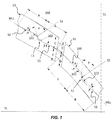
Figure 1 is a plan view of some tread components according to the present invention; -
Figure 2 is a top view of a portion of a tread according to the invention; -
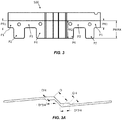
Figure 3 is a side view of a first lamina for the implementation of a first sipe according to the present invention; -
Figure 3A is a plan view of the first lamina; -
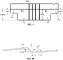
Figure 4 is a side view of a second lamina for the implementation of a second sipe according to the present invention; -
Figure 4A is a plan view of the first lamina; -
Figure 5 is a perspective view of a pneumatic tyre according to the present invention; -
Figures 6 to 9 are graphs showing the trend of the tread performance of the tread under condition of a wet and/or snow-covered surface, in varying the shape of the sipes. - Some embodiments of the present invention will be described below, making reference to the above figures.
- With initial reference to
Figure 1 , this shows, from above, some of thetread components - In particular, a
tread component sipe 100, 200 such to reproduce a broken line on the contact surface thereof. - According to one embodiment, the broken line constitutes three consecutive segments S1, S2, S3, respectively inclined with respect to a longitudinal median line MLL of the same component.
- "Median line MLL" refers to a straight line which passes through the component longitudinally, preferably substantially transversely dividing it in half.
- Preferably, the three segments S1, S2, S3 of the broken line L1, L2 comprise an outer segment S1 inclined by an angle α with respect to the longitudinal median line MLL and an inner segment S3 inclined by an angle β with respect to the longitudinal median line MLL. Preferably, the angles α and β are alternate interior angles.
- According to some embodiments, the angle α is between about 4° and about 6°, preferably equal to about 5°. According to other embodiments, the angle α is between about -4° and about -6°, preferably equal to about -5°.
- According to some embodiments, the angle β is equal to -α.
- Moreover, according to some embodiments, the three segments of the broken line comprise a central segment S2 inclined by about 35°-55°, preferably of about 45° with respect to said longitudinal median line MLL.
- Advantageously, the shape of the sipe may be such that the central segment S2 and the median line MLL intersect at the respective midpoints thereof. In this way, the sipe is arranged symmetrically with respect to the component that contains it.
- According to some embodiments, the
sipe 100, 200 further comprises at least apocket region - In particular, the
pocket region - Of course, embodiments may be provided for that do not have pocket regions, or that provide for a single pocket region for each sipe, or else that provide for two thereof. It is to be understood that each of the sipes may or may not include one or two pocket regions.
- With reference to
Figure 2 , atread 1 according to the present invention, preferably applicable to a four-seasons type pneumatic tyre, comprises a sequence oftread elements 5 arranged in succession and interspersed withfirst grooves 6. - Each
tread element 5 has an overall "V" shape with two lateral wings 7, 7'. - Each of said lateral wings 7, 7' is formed from three tread blocks 11, 21, 31, separated by
second grooves shoulder block 11, amedian block 21 and acentral block 31. - According to the present invention, at least one of the three
tread components median block 21 and thecentral block 31. - In order to ensure the desired best result in terms of performance both on wet surfaces and on snow-covered surfaces, a further parameter that can be taken into consideration is the overall structural rigidity of the single block.
- With reference to
Figures 3, 3A ,4 and 4A , these show, respectively, afirst lamina 500 and asecond lamina 600, that can be used for the implementation of the tread according to the present invention. From the figures it can be seen how, in order to obtain optimal behavior, eachsipe 100, 200 may comprise two or more sipe portions P1, P2, P3, P4 having respective differing depths, in relation to a maximum overall depth PMAX of thesipe 100. - In particular, for each sipe, sipe portions P1, P2, P3, P4 of different depths may be provided for on at least one of the consecutive segments S1, S2, S3. Preferably, these portions are provided, symmetrically identical to each other, on each of the inner S1 and outer S3 segments of each
sipe 100, 200. - The geometry of these sipe portions has been defined by selecting measurements that are such to enable the best possible performance.
- Advantageously, at least a first sipe portion has, with respect to the contact surface Sc, a first depth of between 40% and 70% of the maximum depth PMAX, preferably about 65%, and at least a second sipe portion has, with respect to the contact surface Sc, a second depth of between 70% and 100% of the maximum depth PMAX, preferably 100%.
- By way of example, preferred embodiments could provide for a maximum depth of between 4 mm and 6.5 mm.
- By way of example,
Figures 3 and 3A show afirst lamina 500 that can be used, according to one embodiment of the present invention, in order to obtain asipe 100 on themedian block 21 of the tread. - The
first lamina 500 is shaped in such a manner that the resultingsipe 100 presents in succession, on each of the outer and inner segments, portions P1, P2, P3, P4 at differing depths. In particular, according to the exemplary embodiment shown, two portions P1 and P3 are provided for, the first depth PR1 (measured from the contact surface Sc) thereof being between about 40% and 70% of the maximum depth PMAX, for example with a maximum depth PMAX equal to 5.6 mm, a possible PR1 measurement is about 3.6 mm. As an alternative to these, two portions P2, P4 are provided for wherein the second depth PR2 thereof (measured from the contact surface Sc) ranges between 70% and 100% of PMAX. For example, for a maximum depth PMAX equal to about 5.6 mm, a possible PR2 measurement is about 5.6 mm. -
Figures 4 and 4A refer instead to asecond lamina 600, that can be used for example in order to implement the sipe 200 in thecentral block 31 of the tread. - In this case, according to the exemplary embodiment shown, on each of the outer and inner segments of the sipe, a portion P5 is provided for, the first depth PR5 thereof (measured from the contact surface Sc) being between about 40% and 70% of the maximum depth PMAX, for example with a maximum depth PMAX equal to 5.6 mm, a possible PR5 measurement is about 3.6 mm.
- Furthermore, a portion P6 is provided for wherein the second depth thereof (measured from the contact surface Sc) ranges between 70% and 100% of PMAX. For example, for a maximum depth PMAX equal to about 5.6 mm, a possible PR6 measurement is about 5.6 mm.
- Finally,
Figures 6 to 9 show graphs wherein parameters are listed that are indicative of the performance of a pneumatic tyre equipped with a tread according to the present invention. In particular, the trends of these parameters are shown in relation to the variation of some geometrical characteristics of thesipes 100, 200. - The present invention has heretofore been described with reference to the preferred embodiments thereof. It is intended that each of the technical solutions implemented in the preferred embodiments described herein by way of example can advantageously be combined in different ways between them, in order to give form to other embodiments, as long as all fall within the scope of protection afforded by the claims recited hereinafter.
Claims (15)
- Tread component (11, 21, 31), comprising a sipe (100, 200) that is such to reproduce a broken line on the contact surface (Sc) of said tread component (11, 21, 31), said broken line consisting of three consecutive segments (S1, S2, S3) formed by an inner segment (S3), a central segment (S2) and an outer segment (S1), respectively inclined with respect to a longitudinal median line (MLL) of said component (21, 31), said longitudinal median line (MLL) being a straight line that runs longitudinally along said component (11, 21, 31) preferably subdividing it substantially at the middle in the transverse direction,
characterized in that said sipe (100, 200) further comprises at least a pocket region (101, 102, 201. 202) at the ends of two consecutive segments (S1, S2, S3),
wherein said three consecutive segments (S1, S2, S3) of the broken line comprise a central segment (S2) inclined by about 35°-55°with respect to said longitudinal median line (MLL), said central segment (S2) and said longitudinal median line (MLL) intersect at the respective midpoints thereof said sipe (100, 200) comprising two pocket regions (101, 102, 201, 202), each implemented laterally to one of said inner (S3) and outer (S1) segments, on the side facing said longitudinal median line (MLL). - Tread component (11, 21, 31) according to claim 1, wherein said three consecutive segments (S1, S2, S3) of the broken line comprise an outer segment (S1) inclined by a first angle (α) with respect to said longitudinal median line (MLL) and an inner segment (S3) inclined by a second angle (β) with respect to said longitudinal median line (MLL).
- Tread component (11, 21, 31) according to claim 2, wherein said outer segment (S1) is inclined in one direction by said first angle (α) with respect to said longitudinal median line (MLL) and said inner segment (S3) is inclined in the opposite direction by said second angle (β) with respect to said longitudinal median line (MLL).
- Tread component (11, 21, 31) according to claim 2 or 3, wherein said first angle (α) is between ±4° and ±6° and said first angle (α) is equal to approximately ±5°.
- Tread component (11, 21, 31) according to one of claims 2 to 4, wherein said second angle (β) is equal to said first angle (α).
- Tread component (11, 21, 31) according to one of claims 1 to 5, wherein said central segment (S2) is inclined by about 45° with respect to said longitudinal median line (MLL).
- Tread component (11, 21, 31) according to one of claims 1 to 6, wherein said at least a pocket region (101, 102, 201, 202) is implemented laterally to one of said inner (S3) or outer (S1) segments, on the side facing said longitudinal median line (MLL).
- Tread component (11, 21, 31) according to one of the preceding claims, wherein said sipe (100, 200) comprises at least two sipe portions (P1, P2, P3, P4; P5, P6) of differing depths.
- Tread component (11, 21, 31) according to claim 8, , wherein said at least two sipe portions (P1, P2, P3, P4; P5, P6) of differing depths comprise at least a first sipe portion (P1, P3; P5) having, with respect to the contact surface (Sc), a first sipe depth (PR1; PR5) between about 40% and 70% of a maximum depth (PMAX) and at least a second sipe portion (P2, P4; P6) having, with respect to the contact surface (Sc), a second sipe depth (PR2; PR6) between about 70% and 100% of a maximum depth (PMAX).
- Tread component (11, 21, 31) according to claim 9, wherein said maximum depth (PMAX) is equal to about 5.6 mm.
- Tread component (11, 21, 31) according to claim 10, wherein said first sipe depth (PR1, PR5) is equal to about 3.6 mm.
- Tread component (11, 21, 31) according to claim 10 or 11, wherein said second sipe depth (PR2; PR6) is equal to about 5.6 mm.
- Tread (1) for an all season pneumatic tyre , comprising a sequence of tread elements (5) arranged in succession and interspersed with first grooves (6), each tread element (5) having an overall "V" shape with two lateral wings (7, 7'), each of said lateral wings (7, 7') being formed from three tread components (11, 21, 31) each according to one of the claims from 1 to 12, separated by second grooves (15, 16) and having a contact surface (Sc).
- Pneumatic tyre (100), comprising a tread having at least a tread component according to any of the preceding claims from 1 to 12.
- All season pneumatic tyre (100), comprising a tread (1) according to claim 13.
Applications Claiming Priority (2)
| Application Number | Priority Date | Filing Date | Title |
|---|---|---|---|
| IT201700149345 | 2017-12-22 | ||
| PCT/IB2018/060289 WO2019123279A1 (en) | 2017-12-22 | 2018-12-18 | Tread component |
Publications (2)
| Publication Number | Publication Date |
|---|---|
| EP3727892A1 EP3727892A1 (en) | 2020-10-28 |
| EP3727892B1 true EP3727892B1 (en) | 2021-05-19 |
Family
ID=61873669
Family Applications (1)
| Application Number | Title | Priority Date | Filing Date |
|---|---|---|---|
| EP18833536.8A Active EP3727892B1 (en) | 2017-12-22 | 2018-12-18 | Tread component |
Country Status (3)
| Country | Link |
|---|---|
| EP (1) | EP3727892B1 (en) |
| CN (1) | CN111511583B (en) |
| WO (1) | WO2019123279A1 (en) |
Family Cites Families (8)
| Publication number | Priority date | Publication date | Assignee | Title |
|---|---|---|---|---|
| EP0235072A2 (en) * | 1986-01-29 | 1987-09-02 | The Goodyear Tire & Rubber Company | All-season pneumatic tire with improved tread stiffness |
| JPH0310910A (en) * | 1989-06-09 | 1991-01-18 | Bridgestone Corp | Heavy duty pneumatic tire |
| US5824169A (en) * | 1995-01-20 | 1998-10-20 | The Goodyear Tire & Rubber Company | Pneumatic tire having improved wear properties |
| KR101286264B1 (en) * | 2011-09-22 | 2013-07-15 | 요코하마 고무 가부시키가이샤 | Pneumatic tire |
| EP2913205B1 (en) * | 2012-10-24 | 2018-06-06 | Bridgestone Corporation | Pneumatic tire |
| JP5961135B2 (en) * | 2013-04-15 | 2016-08-02 | 住友ゴム工業株式会社 | Pneumatic tire |
| JP5841558B2 (en) * | 2013-04-23 | 2016-01-13 | 住友ゴム工業株式会社 | Pneumatic tire |
| CN110722934B (en) * | 2014-06-19 | 2021-12-07 | 倍耐力轮胎股份公司 | Vehicle tyre |
-
2018
- 2018-12-18 EP EP18833536.8A patent/EP3727892B1/en active Active
- 2018-12-18 CN CN201880082646.5A patent/CN111511583B/en active Active
- 2018-12-18 WO PCT/IB2018/060289 patent/WO2019123279A1/en not_active Ceased
Also Published As
| Publication number | Publication date |
|---|---|
| CN111511583A (en) | 2020-08-07 |
| CN111511583B (en) | 2023-03-14 |
| EP3727892A1 (en) | 2020-10-28 |
| WO2019123279A1 (en) | 2019-06-27 |
Similar Documents
| Publication | Publication Date | Title |
|---|---|---|
| JP4223064B2 (en) | Pneumatic tire | |
| EP3086957B1 (en) | Tyre for vehicle wheels having improved tread pattern | |
| US6892775B1 (en) | Pneumatic radial tire for all-season passenger car | |
| US8967210B2 (en) | Pneumatic tire with tread having zigzag sipes and narrow grooves | |
| US12151514B2 (en) | Pneumatic tire | |
| CN108367623B (en) | Vehicle Pneumatic Tires | |
| US20180065416A1 (en) | Tire With A Directional Tread Comprising Alternate Curved Blocks And Grooves | |
| CA2433823C (en) | Pneumatic tire for use on iced and snowed road surfaces | |
| CN105691111A (en) | heavy duty pneumatic tire | |
| EP3867081B1 (en) | Tread for a winter pneumatic tyre and a winter pneumatic tyre | |
| RU2531435C2 (en) | Winter tire | |
| US8245744B2 (en) | Tire with tread having Z-shaped sipes in circumferential rib | |
| EP2930036B1 (en) | Pneumatic tire | |
| EP3727892B1 (en) | Tread component | |
| EP0485884A1 (en) | Sipes for tire treads | |
| JP4872004B2 (en) | Pneumatic tire | |
| US20050211353A1 (en) | Vehicle pneumatic tire | |
| US11453246B2 (en) | Tire | |
| US9944130B2 (en) | Tire having grooves comprising sipes and/or other cross-groove negative geometry | |
| US10953698B2 (en) | Tread for heavy goods vehicle winter tire | |
| CN112384377A (en) | Tread with improved snow performance | |
| CN106232392A (en) | Pneumatic vehicle tire | |
| CN108482021B (en) | AT tire with snow traction performance | |
| CN111655514B (en) | Pneumatic tire | |
| JPH02171305A (en) | Projected elements of pneumatic tire |
Legal Events
| Date | Code | Title | Description |
|---|---|---|---|
| STAA | Information on the status of an ep patent application or granted ep patent |
Free format text: STATUS: UNKNOWN |
|
| STAA | Information on the status of an ep patent application or granted ep patent |
Free format text: STATUS: THE INTERNATIONAL PUBLICATION HAS BEEN MADE |
|
| PUAI | Public reference made under article 153(3) epc to a published international application that has entered the european phase |
Free format text: ORIGINAL CODE: 0009012 |
|
| STAA | Information on the status of an ep patent application or granted ep patent |
Free format text: STATUS: REQUEST FOR EXAMINATION WAS MADE |
|
| 17P | Request for examination filed |
Effective date: 20200721 |
|
| AK | Designated contracting states |
Kind code of ref document: A1 Designated state(s): AL AT BE BG CH CY CZ DE DK EE ES FI FR GB GR HR HU IE IS IT LI LT LU LV MC MK MT NL NO PL PT RO RS SE SI SK SM TR |
|
| AX | Request for extension of the european patent |
Extension state: BA ME |
|
| GRAP | Despatch of communication of intention to grant a patent |
Free format text: ORIGINAL CODE: EPIDOSNIGR1 |
|
| STAA | Information on the status of an ep patent application or granted ep patent |
Free format text: STATUS: GRANT OF PATENT IS INTENDED |
|
| DAV | Request for validation of the european patent (deleted) | ||
| DAX | Request for extension of the european patent (deleted) | ||
| INTG | Intention to grant announced |
Effective date: 20201215 |
|
| RIN1 | Information on inventor provided before grant (corrected) |
Inventor name: DE LIDDO, MARCO Inventor name: SANTANGELI, FABIO Inventor name: SPARACINO, ANDREA |
|
| GRAS | Grant fee paid |
Free format text: ORIGINAL CODE: EPIDOSNIGR3 |
|
| GRAA | (expected) grant |
Free format text: ORIGINAL CODE: 0009210 |
|
| STAA | Information on the status of an ep patent application or granted ep patent |
Free format text: STATUS: THE PATENT HAS BEEN GRANTED |
|
| AK | Designated contracting states |
Kind code of ref document: B1 Designated state(s): AL AT BE BG CH CY CZ DE DK EE ES FI FR GB GR HR HU IE IS IT LI LT LU LV MC MK MT NL NO PL PT RO RS SE SI SK SM TR |
|
| REG | Reference to a national code |
Ref country code: GB Ref legal event code: FG4D |
|
| REG | Reference to a national code |
Ref country code: CH Ref legal event code: EP |
|
| REG | Reference to a national code |
Ref country code: DE Ref legal event code: R096 Ref document number: 602018017461 Country of ref document: DE |
|
| REG | Reference to a national code |
Ref country code: AT Ref legal event code: REF Ref document number: 1393633 Country of ref document: AT Kind code of ref document: T Effective date: 20210615 |
|
| REG | Reference to a national code |
Ref country code: IE Ref legal event code: FG4D |
|
| REG | Reference to a national code |
Ref country code: LT Ref legal event code: MG9D |
|
| REG | Reference to a national code |
Ref country code: AT Ref legal event code: MK05 Ref document number: 1393633 Country of ref document: AT Kind code of ref document: T Effective date: 20210519 |
|
| REG | Reference to a national code |
Ref country code: NL Ref legal event code: MP Effective date: 20210519 |
|
| PG25 | Lapsed in a contracting state [announced via postgrant information from national office to epo] |
Ref country code: HR Free format text: LAPSE BECAUSE OF FAILURE TO SUBMIT A TRANSLATION OF THE DESCRIPTION OR TO PAY THE FEE WITHIN THE PRESCRIBED TIME-LIMIT Effective date: 20210519 Ref country code: LT Free format text: LAPSE BECAUSE OF FAILURE TO SUBMIT A TRANSLATION OF THE DESCRIPTION OR TO PAY THE FEE WITHIN THE PRESCRIBED TIME-LIMIT Effective date: 20210519 Ref country code: FI Free format text: LAPSE BECAUSE OF FAILURE TO SUBMIT A TRANSLATION OF THE DESCRIPTION OR TO PAY THE FEE WITHIN THE PRESCRIBED TIME-LIMIT Effective date: 20210519 Ref country code: AT Free format text: LAPSE BECAUSE OF FAILURE TO SUBMIT A TRANSLATION OF THE DESCRIPTION OR TO PAY THE FEE WITHIN THE PRESCRIBED TIME-LIMIT Effective date: 20210519 Ref country code: BG Free format text: LAPSE BECAUSE OF FAILURE TO SUBMIT A TRANSLATION OF THE DESCRIPTION OR TO PAY THE FEE WITHIN THE PRESCRIBED TIME-LIMIT Effective date: 20210819 |
|
| PG25 | Lapsed in a contracting state [announced via postgrant information from national office to epo] |
Ref country code: PT Free format text: LAPSE BECAUSE OF FAILURE TO SUBMIT A TRANSLATION OF THE DESCRIPTION OR TO PAY THE FEE WITHIN THE PRESCRIBED TIME-LIMIT Effective date: 20210920 Ref country code: SE Free format text: LAPSE BECAUSE OF FAILURE TO SUBMIT A TRANSLATION OF THE DESCRIPTION OR TO PAY THE FEE WITHIN THE PRESCRIBED TIME-LIMIT Effective date: 20210519 Ref country code: RS Free format text: LAPSE BECAUSE OF FAILURE TO SUBMIT A TRANSLATION OF THE DESCRIPTION OR TO PAY THE FEE WITHIN THE PRESCRIBED TIME-LIMIT Effective date: 20210519 Ref country code: LV Free format text: LAPSE BECAUSE OF FAILURE TO SUBMIT A TRANSLATION OF THE DESCRIPTION OR TO PAY THE FEE WITHIN THE PRESCRIBED TIME-LIMIT Effective date: 20210519 Ref country code: NO Free format text: LAPSE BECAUSE OF FAILURE TO SUBMIT A TRANSLATION OF THE DESCRIPTION OR TO PAY THE FEE WITHIN THE PRESCRIBED TIME-LIMIT Effective date: 20210819 Ref country code: PL Free format text: LAPSE BECAUSE OF FAILURE TO SUBMIT A TRANSLATION OF THE DESCRIPTION OR TO PAY THE FEE WITHIN THE PRESCRIBED TIME-LIMIT Effective date: 20210519 Ref country code: GR Free format text: LAPSE BECAUSE OF FAILURE TO SUBMIT A TRANSLATION OF THE DESCRIPTION OR TO PAY THE FEE WITHIN THE PRESCRIBED TIME-LIMIT Effective date: 20210820 Ref country code: IS Free format text: LAPSE BECAUSE OF FAILURE TO SUBMIT A TRANSLATION OF THE DESCRIPTION OR TO PAY THE FEE WITHIN THE PRESCRIBED TIME-LIMIT Effective date: 20210919 |
|
| PG25 | Lapsed in a contracting state [announced via postgrant information from national office to epo] |
Ref country code: NL Free format text: LAPSE BECAUSE OF FAILURE TO SUBMIT A TRANSLATION OF THE DESCRIPTION OR TO PAY THE FEE WITHIN THE PRESCRIBED TIME-LIMIT Effective date: 20210519 |
|
| PG25 | Lapsed in a contracting state [announced via postgrant information from national office to epo] |
Ref country code: SK Free format text: LAPSE BECAUSE OF FAILURE TO SUBMIT A TRANSLATION OF THE DESCRIPTION OR TO PAY THE FEE WITHIN THE PRESCRIBED TIME-LIMIT Effective date: 20210519 Ref country code: ES Free format text: LAPSE BECAUSE OF FAILURE TO SUBMIT A TRANSLATION OF THE DESCRIPTION OR TO PAY THE FEE WITHIN THE PRESCRIBED TIME-LIMIT Effective date: 20210519 Ref country code: EE Free format text: LAPSE BECAUSE OF FAILURE TO SUBMIT A TRANSLATION OF THE DESCRIPTION OR TO PAY THE FEE WITHIN THE PRESCRIBED TIME-LIMIT Effective date: 20210519 Ref country code: RO Free format text: LAPSE BECAUSE OF FAILURE TO SUBMIT A TRANSLATION OF THE DESCRIPTION OR TO PAY THE FEE WITHIN THE PRESCRIBED TIME-LIMIT Effective date: 20210519 Ref country code: SM Free format text: LAPSE BECAUSE OF FAILURE TO SUBMIT A TRANSLATION OF THE DESCRIPTION OR TO PAY THE FEE WITHIN THE PRESCRIBED TIME-LIMIT Effective date: 20210519 Ref country code: DK Free format text: LAPSE BECAUSE OF FAILURE TO SUBMIT A TRANSLATION OF THE DESCRIPTION OR TO PAY THE FEE WITHIN THE PRESCRIBED TIME-LIMIT Effective date: 20210519 Ref country code: CZ Free format text: LAPSE BECAUSE OF FAILURE TO SUBMIT A TRANSLATION OF THE DESCRIPTION OR TO PAY THE FEE WITHIN THE PRESCRIBED TIME-LIMIT Effective date: 20210519 |
|
| REG | Reference to a national code |
Ref country code: DE Ref legal event code: R097 Ref document number: 602018017461 Country of ref document: DE |
|
| PLBE | No opposition filed within time limit |
Free format text: ORIGINAL CODE: 0009261 |
|
| STAA | Information on the status of an ep patent application or granted ep patent |
Free format text: STATUS: NO OPPOSITION FILED WITHIN TIME LIMIT |
|
| 26N | No opposition filed |
Effective date: 20220222 |
|
| PG25 | Lapsed in a contracting state [announced via postgrant information from national office to epo] |
Ref country code: IS Free format text: LAPSE BECAUSE OF FAILURE TO SUBMIT A TRANSLATION OF THE DESCRIPTION OR TO PAY THE FEE WITHIN THE PRESCRIBED TIME-LIMIT Effective date: 20210919 Ref country code: AL Free format text: LAPSE BECAUSE OF FAILURE TO SUBMIT A TRANSLATION OF THE DESCRIPTION OR TO PAY THE FEE WITHIN THE PRESCRIBED TIME-LIMIT Effective date: 20210519 |
|
| PG25 | Lapsed in a contracting state [announced via postgrant information from national office to epo] |
Ref country code: MC Free format text: LAPSE BECAUSE OF FAILURE TO SUBMIT A TRANSLATION OF THE DESCRIPTION OR TO PAY THE FEE WITHIN THE PRESCRIBED TIME-LIMIT Effective date: 20210519 Ref country code: IT Free format text: LAPSE BECAUSE OF FAILURE TO SUBMIT A TRANSLATION OF THE DESCRIPTION OR TO PAY THE FEE WITHIN THE PRESCRIBED TIME-LIMIT Effective date: 20210519 |
|
| REG | Reference to a national code |
Ref country code: CH Ref legal event code: PL |
|
| REG | Reference to a national code |
Ref country code: BE Ref legal event code: MM Effective date: 20211231 |
|
| PG25 | Lapsed in a contracting state [announced via postgrant information from national office to epo] |
Ref country code: LU Free format text: LAPSE BECAUSE OF NON-PAYMENT OF DUE FEES Effective date: 20211218 Ref country code: IE Free format text: LAPSE BECAUSE OF NON-PAYMENT OF DUE FEES Effective date: 20211218 |
|
| PG25 | Lapsed in a contracting state [announced via postgrant information from national office to epo] |
Ref country code: BE Free format text: LAPSE BECAUSE OF NON-PAYMENT OF DUE FEES Effective date: 20211231 |
|
| PG25 | Lapsed in a contracting state [announced via postgrant information from national office to epo] |
Ref country code: LI Free format text: LAPSE BECAUSE OF NON-PAYMENT OF DUE FEES Effective date: 20211231 Ref country code: CH Free format text: LAPSE BECAUSE OF NON-PAYMENT OF DUE FEES Effective date: 20211231 |
|
| PG25 | Lapsed in a contracting state [announced via postgrant information from national office to epo] |
Ref country code: CY Free format text: LAPSE BECAUSE OF FAILURE TO SUBMIT A TRANSLATION OF THE DESCRIPTION OR TO PAY THE FEE WITHIN THE PRESCRIBED TIME-LIMIT Effective date: 20210519 |
|
| PG25 | Lapsed in a contracting state [announced via postgrant information from national office to epo] |
Ref country code: HU Free format text: LAPSE BECAUSE OF FAILURE TO SUBMIT A TRANSLATION OF THE DESCRIPTION OR TO PAY THE FEE WITHIN THE PRESCRIBED TIME-LIMIT; INVALID AB INITIO Effective date: 20181218 |
|
| GBPC | Gb: european patent ceased through non-payment of renewal fee |
Effective date: 20221218 |
|
| PG25 | Lapsed in a contracting state [announced via postgrant information from national office to epo] |
Ref country code: GB Free format text: LAPSE BECAUSE OF NON-PAYMENT OF DUE FEES Effective date: 20221218 |
|
| PG25 | Lapsed in a contracting state [announced via postgrant information from national office to epo] |
Ref country code: MK Free format text: LAPSE BECAUSE OF FAILURE TO SUBMIT A TRANSLATION OF THE DESCRIPTION OR TO PAY THE FEE WITHIN THE PRESCRIBED TIME-LIMIT Effective date: 20210519 |
|
| PG25 | Lapsed in a contracting state [announced via postgrant information from national office to epo] |
Ref country code: TR Free format text: LAPSE BECAUSE OF FAILURE TO SUBMIT A TRANSLATION OF THE DESCRIPTION OR TO PAY THE FEE WITHIN THE PRESCRIBED TIME-LIMIT Effective date: 20210519 |
|
| PG25 | Lapsed in a contracting state [announced via postgrant information from national office to epo] |
Ref country code: MT Free format text: LAPSE BECAUSE OF FAILURE TO SUBMIT A TRANSLATION OF THE DESCRIPTION OR TO PAY THE FEE WITHIN THE PRESCRIBED TIME-LIMIT Effective date: 20210519 |
|
| PGFP | Annual fee paid to national office [announced via postgrant information from national office to epo] |
Ref country code: DE Payment date: 20251126 Year of fee payment: 8 |
|
| PGFP | Annual fee paid to national office [announced via postgrant information from national office to epo] |
Ref country code: FR Payment date: 20251120 Year of fee payment: 8 |