EP3727554B1 - Medical balloon - Google Patents
Medical balloon Download PDFInfo
- Publication number
- EP3727554B1 EP3727554B1 EP18830260.8A EP18830260A EP3727554B1 EP 3727554 B1 EP3727554 B1 EP 3727554B1 EP 18830260 A EP18830260 A EP 18830260A EP 3727554 B1 EP3727554 B1 EP 3727554B1
- Authority
- EP
- European Patent Office
- Prior art keywords
- textile tube
- woven textile
- yarn filaments
- tube
- medical balloon
- Prior art date
- Legal status (The legal status is an assumption and is not a legal conclusion. Google has not performed a legal analysis and makes no representation as to the accuracy of the status listed.)
- Active
Links
Images


Classifications
-
- A—HUMAN NECESSITIES
- A61—MEDICAL OR VETERINARY SCIENCE; HYGIENE
- A61M—DEVICES FOR INTRODUCING MEDIA INTO, OR ONTO, THE BODY; DEVICES FOR TRANSDUCING BODY MEDIA OR FOR TAKING MEDIA FROM THE BODY; DEVICES FOR PRODUCING OR ENDING SLEEP OR STUPOR
- A61M25/00—Catheters; Hollow probes
- A61M25/10—Balloon catheters
- A61M25/1027—Making of balloon catheters
-
- A—HUMAN NECESSITIES
- A61—MEDICAL OR VETERINARY SCIENCE; HYGIENE
- A61M—DEVICES FOR INTRODUCING MEDIA INTO, OR ONTO, THE BODY; DEVICES FOR TRANSDUCING BODY MEDIA OR FOR TAKING MEDIA FROM THE BODY; DEVICES FOR PRODUCING OR ENDING SLEEP OR STUPOR
- A61M25/00—Catheters; Hollow probes
- A61M25/10—Balloon catheters
-
- A—HUMAN NECESSITIES
- A61—MEDICAL OR VETERINARY SCIENCE; HYGIENE
- A61M—DEVICES FOR INTRODUCING MEDIA INTO, OR ONTO, THE BODY; DEVICES FOR TRANSDUCING BODY MEDIA OR FOR TAKING MEDIA FROM THE BODY; DEVICES FOR PRODUCING OR ENDING SLEEP OR STUPOR
- A61M25/00—Catheters; Hollow probes
- A61M25/10—Balloon catheters
- A61M25/1027—Making of balloon catheters
- A61M25/1029—Production methods of the balloon members, e.g. blow-moulding, extruding, deposition or by wrapping a plurality of layers of balloon material around a mandril
-
- A—HUMAN NECESSITIES
- A61—MEDICAL OR VETERINARY SCIENCE; HYGIENE
- A61M—DEVICES FOR INTRODUCING MEDIA INTO, OR ONTO, THE BODY; DEVICES FOR TRANSDUCING BODY MEDIA OR FOR TAKING MEDIA FROM THE BODY; DEVICES FOR PRODUCING OR ENDING SLEEP OR STUPOR
- A61M25/00—Catheters; Hollow probes
- A61M25/10—Balloon catheters
- A61M2025/1043—Balloon catheters with special features or adapted for special applications
- A61M2025/1075—Balloon catheters with special features or adapted for special applications having a balloon composed of several layers, e.g. by coating or embedding
-
- A—HUMAN NECESSITIES
- A61—MEDICAL OR VETERINARY SCIENCE; HYGIENE
- A61M—DEVICES FOR INTRODUCING MEDIA INTO, OR ONTO, THE BODY; DEVICES FOR TRANSDUCING BODY MEDIA OR FOR TAKING MEDIA FROM THE BODY; DEVICES FOR PRODUCING OR ENDING SLEEP OR STUPOR
- A61M25/00—Catheters; Hollow probes
- A61M25/10—Balloon catheters
- A61M2025/1043—Balloon catheters with special features or adapted for special applications
- A61M2025/1084—Balloon catheters with special features or adapted for special applications having features for increasing the shape stability, the reproducibility or for limiting expansion, e.g. containments, wrapped around fibres, yarns or strands
Definitions
- This invention relates to medical balloon for high pressure angioplasty.
- High pressure balloon catheters are used in vascular angioplasty to break open heavily calcified or highly stenotic lesions, including coronary, peripheral, neurovascular and structural heart applications.
- One example is the use of high pressure balloons for vascular access to arteriovenous shunts used in kidney dialysis, where patients will need repeated access to the shunts. These shunts become highly stenotic over time and require high pressure balloons to open.
- Other applications include peripheral angioplasty balloons to break open highly calcified vascular lesions, valvuloplasty to break open calcified heart valves in preparation for valve repair/replacement, and high pressure non-compliant balloons used in coronary angioplasty and for coronary stent placement.
- a known medical balloon forming process involves blowing a thin film of polymer material (or multiple layers of different polymers) into the shape of a balloon in a thermal forming process. This process has reached the limit because of the design trade-off between low profile and high strength.
- the state of the art for high pressure balloons involves braiding a textile material over a film blown balloon. However, the balloons are still prone to bursting at high pressure, potentially resulting in the loss of balloon material within the venous system of the patient.
- PCT Publication No. WO 2006/034396 discloses a surgical balloon that can be woven, knitted or braided and can withstand extreme pressures relative to other surgical balloons.
- 2005/271844 discloses a medical device formed from at least one first layer defining the shape of the medical device, the first layer having an inner surface and an outer surface and a web formed with silk fiber provided over at least a portion of the inner surface, the outer surface or both of the first layer.
- United States Patent Publication No. 2003/204235 discloses an implantable tubular textile prosthesis comprising a biocompatible fabric, the fabric having a textile construction comprising cold drawn PTFE yarns having a substantially uniform denier and high molecular orientation.
- the textile tube may be coated with said polymer material on both its inner and outer surfaces.
- the textile tube has a longitudinal axis and comprises a plurality of yarn filaments aligned with said longitudinal axis and a plurality of yarn filaments arranged circumferentially around the tube perpendicular to said longitudinal axis.
- the textile tube may be formed from multi-filament yarns, mono-filament yarns or a mixture of multi-filament and mono-filament yarns.
- the yarns forming the textile tube may range from 5 to 500 denier.
- the yarns forming said textile tube may comprise one or more of regenerated silk viscose, nylon, PET, UHMWPE, LCP (liquid crystal polymer), polyurethane, polypropylene, HDPE, pebax, polyester, Rayon, polytetrafluoroethylene (PTFE), polyamide, carbon, glass fibre, cotton, collagen, calcium alginate, bio-absorbable (e.g. Polyglycolic acid (PGA), 100% PGA, Polyglycolic acid-co-poly-L-lactic acid (PGA/PLLA), Poly-L-lactic acid (PLLA), 100% PLLA.
- PGA Polyglycolic acid
- PGA/PLLA Polyglycolic acid-co-poly-L-lactic acid
- PLLA Poly-L-lactic acid
- the yarns forming the textile tube range from 0.025mm to 3.0mm in diameter.
- At least some of the yarns forming the textile tube are ring spun.
- At least some of the yarns forming the textile tube are twisted.
- the yarns may comprise a mixture of two or more different materials.
- the polymer material coating the textile tube may comprise polyurethane.
- the method may comprise coating both the inner and outer surfaces of the textile tube with said polymer material.
- the method comprises the steps of coating an outer surface of the textile tube with a polymer material, everting the tube and coating the inner surface (now the outer surface) with a polymer material.
- the inner and outer surfaces of the textile tube may be coated with said polymer material by a dispersion process.
- At least the outer surface of the textile tube is coated with said polymer material by dipping the textile tube in said polymer material in liquid form.
- the method may comprise the step of heating the textile tube in order to effect reflow of at least some yarns forming the textile tube.
- the textile tube may be located on a mandrel during coating with said polymer material.
- the method may comprise the step of heating the mandrel in order to effect reflow of at least some yarns forming the textile tube.
- the present invention takes an entirely new approach by weaving a seamless textile tube in the shape of a balloon using high strength polymer yarns in a low profile configuration.
- the textile is subsequently sealed by applying a polymer material using a solution dispersion or dip coating method.
- a medical balloon for high pressure vascular angioplasty comprises a seamless textile fabric tube that has been knitted or woven into the shape of a three dimensional cylindrical balloon.
- the tube may have fibres/yarns running both axially around the circumference and longitudinally along the length thereof.
- the outer and inner surfaces of the textile tube are coated with a polymer material to seal the tube, thus defining an inflatable balloon and allowing the resulting balloon to be inflated.
- the resulting medical balloon offers resilient mechanical structure with excellent compliance when inflated to high pressures (i.e. 30 - 50 ATM).
- Coating/sealing the textile tube with a polymer material allows the balloon to be inflated as a monolithic structure.
- prior art medical balloons incorporate an already formed / blown balloon where a yarn or textile is then placed over the balloon as a secondary process of offer structure / compliance when inflated.
- the textile tube may comprise monofilament yarns, multifilament yarns (which may be heatset in a twisted condition or not) or a combination of both.
- the textile tube may be formed from ring spun yarns of regenerated silk, nylon/high tension nylon, PET/high tension PET, UHMWPE, LCP (liquid crystal polymer), polyurethane, polypropylene, HDPE, pebax, polyester, Rayon, polytetrafluoroethylene (PTFE), polyamide, carbon, glass fibre, cotton, collagen, calcium alginate, bio-absorbable (e.g.
- Yarns can be a mixture of high tension and low melt temperature with the addition of weldable yarns to aid construction.
- the yarn forming the textile tube may range from 5 to 500 denier.
- the textile tube may also be formed from a combination of yarns of different materials and/or each yarn may be a combination of fibres of different materials. For example mixing PET with nylon fibres would enable bonding the balloon to other components, as nylon has a relatively low melt temperature compared with PET, which would provide additional strength.
- the woven textile can include yarns of Nylon material, such as PA6 or PA12 yarns, to make the balloon compatible with downstream heat bonding processes during catheter assembly to facilitate bonding of the balloon to a catheter shaft.
- Nylon material such as PA6 or PA12 yarns
- the medical balloon in accordance with the present invention may be made by firstly creating the woven textile tube 2 by a suitable weaving process.
- the textile tube 2 comprises a longitudinal tubular body having narrowed end regions 4,6 adapted to fit over a catheter shaft and a reinforced central region 8 having a selected diameter to suit the application for which the balloon is intended to be used.
- the outer surface of the textile tube is coated with a suitable polymer material 10, such as polyurethane, by a dispersion process such as spraying, to seal the tube 2.
- a suitable polymer material such as polyurethane
- the tube may be placed over a mandrel during such process.
- the textile tube may be everted (turned inside out), as shown in Figure 4 , and the inner surface 12 of the tube, now facing outwards, may be coated with the polymer material by repeating the dispersion process.
- the second coating layer has dried/cured, the resulting balloon may be everted once again to form the finished product.
- a medical balloon in accordance with the present invention may be made by dip coating the woven textile tube 2 with a polymer material 10.
- the textile tube 2 may be mounted onto a shaped mandrel and gripped at one end before being dipped into and then withdrawn from a vessel 14 containing the polymer material 10.
- the textile tube 2 may then be everted as per Figure 4 to dip coat the inner surface of the tube in a further step.
- the textile tube 2 may be subjected to a heating step in order to effect reflow of some or all of the yarns forming the textile tube 2, whereby the heat softens the yarns and causes adjacent and/or overlapping yarns to partially melt together in order to increase the integrity and strength of the textile tube 2 and thus ultimately the medical balloon.
- the heating step may for example be undertaken by heating the mandrel on which the textile tube 2 is mounted for coating with the polymer material 10.
- the application of heat may result in some of the yarns partially melting and reflowing around other un-melted yarns.
Landscapes
- Health & Medical Sciences (AREA)
- Heart & Thoracic Surgery (AREA)
- Life Sciences & Earth Sciences (AREA)
- Engineering & Computer Science (AREA)
- Biomedical Technology (AREA)
- Pulmonology (AREA)
- Biophysics (AREA)
- Anesthesiology (AREA)
- Child & Adolescent Psychology (AREA)
- Hematology (AREA)
- Animal Behavior & Ethology (AREA)
- General Health & Medical Sciences (AREA)
- Public Health (AREA)
- Veterinary Medicine (AREA)
- Manufacturing & Machinery (AREA)
- Materials For Medical Uses (AREA)
Description
- This invention relates to medical balloon for high pressure angioplasty.
- High pressure balloon catheters are used in vascular angioplasty to break open heavily calcified or highly stenotic lesions, including coronary, peripheral, neurovascular and structural heart applications. One example is the use of high pressure balloons for vascular access to arteriovenous shunts used in kidney dialysis, where patients will need repeated access to the shunts. These shunts become highly stenotic over time and require high pressure balloons to open. Other applications include peripheral angioplasty balloons to break open highly calcified vascular lesions, valvuloplasty to break open calcified heart valves in preparation for valve repair/replacement, and high pressure non-compliant balloons used in coronary angioplasty and for coronary stent placement.
- A known medical balloon forming process involves blowing a thin film of polymer material (or multiple layers of different polymers) into the shape of a balloon in a thermal forming process. This process has reached the limit because of the design trade-off between low profile and high strength. The state of the art for high pressure balloons involves braiding a textile material over a film blown balloon. However, the balloons are still prone to bursting at high pressure, potentially resulting in the loss of balloon material within the venous system of the patient.
PCT Publication No. WO 2006/034396 discloses a surgical balloon that can be woven, knitted or braided and can withstand extreme pressures relative to other surgical balloons.United States Patent Publication No. 2005/271844 discloses a medical device formed from at least one first layer defining the shape of the medical device, the first layer having an inner surface and an outer surface and a web formed with silk fiber provided over at least a portion of the inner surface, the outer surface or both of the first layer.United States Patent Publication No. 2003/204235 discloses an implantable tubular textile prosthesis comprising a biocompatible fabric, the fabric having a textile construction comprising cold drawn PTFE yarns having a substantially uniform denier and high molecular orientation. - In accordance with a first embodiment of the present invention there is provided a medical balloon according to claim 1.
- The textile tube may be coated with said polymer material on both its inner and outer surfaces.
- In a preferred embodiment the textile tube has a longitudinal axis and comprises a plurality of yarn filaments aligned with said longitudinal axis and a plurality of yarn filaments arranged circumferentially around the tube perpendicular to said longitudinal axis.
- The textile tube may be formed from multi-filament yarns, mono-filament yarns or a mixture of multi-filament and mono-filament yarns.
- The yarns forming the textile tube may range from 5 to 500 denier.
- The yarns forming said textile tube may comprise one or more of regenerated silk viscose, nylon, PET, UHMWPE, LCP (liquid crystal polymer), polyurethane, polypropylene, HDPE, pebax, polyester, Rayon, polytetrafluoroethylene (PTFE), polyamide, carbon, glass fibre, cotton, collagen, calcium alginate, bio-absorbable (e.g. Polyglycolic acid (PGA), 100% PGA, Polyglycolic acid-co-poly-L-lactic acid (PGA/PLLA), Poly-L-lactic acid (PLLA), 100% PLLA.
- The yarns forming the textile tube range from 0.025mm to 3.0mm in diameter.
- At least some of the yarns forming the textile tube are ring spun.
- At least some of the yarns forming the textile tube are twisted.
- The yarns may comprise a mixture of two or more different materials.
- The polymer material coating the textile tube may comprise polyurethane.
- According to a further aspect of the present invention there is provided a method according to claim 9.
- The method may comprise coating both the inner and outer surfaces of the textile tube with said polymer material.
- In a preferred embodiment the method comprises the steps of coating an outer surface of the textile tube with a polymer material, everting the tube and coating the inner surface (now the outer surface) with a polymer material.
- In one embodiment the inner and outer surfaces of the textile tube may be coated with said polymer material by a dispersion process.
- In an alternative embodiment at least the outer surface of the textile tube is coated with said polymer material by dipping the textile tube in said polymer material in liquid form.
- The method may comprise the step of heating the textile tube in order to effect reflow of at least some yarns forming the textile tube.
- The textile tube may be located on a mandrel during coating with said polymer material.
- The method may comprise the step of heating the mandrel in order to effect reflow of at least some yarns forming the textile tube.
- A medical balloon and its method of manufacture in accordance with embodiments of the present invention will now be described, by way of example only, with reference to the accompanying drawings, in which :-
-
Figure 1 illustrates a textile tube forming part of a medical balloon in accordance with an embodiment of the present invention; -
Figure 2 illustrates the textile tube fromFigure 1 being spray coated with a polymer layer using a dispersion coating machine to seal the outer surface of the textile tube; -
Figure 3 illustrates the textile tube ofFigure 1 whose outer surface has been completely coated in polymer material; -
Figure 4 illustrates the action of completely everting the coated textile balloon in order to expose the uncoated inner surface to the outside. The inner surface, now facing outwards would again be coated as perFigure 2 ; and -
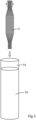
Fig 5 illustrates an alternative method of application of a polymer material to seal the outer surface of the textile tube. - The present invention takes an entirely new approach by weaving a seamless textile tube in the shape of a balloon using high strength polymer yarns in a low profile configuration. The textile is subsequently sealed by applying a polymer material using a solution dispersion or dip coating method.
- According to an embodiment of the present invention a medical balloon for high pressure vascular angioplasty comprises a seamless textile fabric tube that has been knitted or woven into the shape of a three dimensional cylindrical balloon.
- The tube may have fibres/yarns running both axially around the circumference and longitudinally along the length thereof.
- The outer and inner surfaces of the textile tube are coated with a polymer material to seal the tube, thus defining an inflatable balloon and allowing the resulting balloon to be inflated.
- The resulting medical balloon offers resilient mechanical structure with excellent compliance when inflated to high pressures (i.e. 30 - 50 ATM).
- Coating/sealing the textile tube with a polymer material allows the balloon to be inflated as a monolithic structure. By comparison, prior art medical balloons incorporate an already formed / blown balloon where a yarn or textile is then placed over the balloon as a secondary process of offer structure / compliance when inflated.
- The textile tube may comprise monofilament yarns, multifilament yarns (which may be heatset in a twisted condition or not) or a combination of both. The textile tube may be formed from ring spun yarns of regenerated silk, nylon/high tension nylon, PET/high tension PET, UHMWPE, LCP (liquid crystal polymer), polyurethane, polypropylene, HDPE, pebax, polyester, Rayon, polytetrafluoroethylene (PTFE), polyamide, carbon, glass fibre, cotton, collagen, calcium alginate, bio-absorbable (e.g. Polyglycolic acid (PGA), 100% PGA, Polyglycolic acid-co-poly-L-lactic acid (PGA/PLLA), Poly-L-lactic acid (PLLA), 100% PLLA.. Yarns can be a mixture of high tension and low melt temperature with the addition of weldable yarns to aid construction. The yarn forming the textile tube may range from 5 to 500 denier. The textile tube may also be formed from a combination of yarns of different materials and/or each yarn may be a combination of fibres of different materials. For example mixing PET with nylon fibres would enable bonding the balloon to other components, as nylon has a relatively low melt temperature compared with PET, which would provide additional strength.
- The woven textile can include yarns of Nylon material, such as PA6 or PA12 yarns, to make the balloon compatible with downstream heat bonding processes during catheter assembly to facilitate bonding of the balloon to a catheter shaft.
- As illustrated in
Figures 1 to 4 , in a first embodiment the medical balloon in accordance with the present invention may be made by firstly creating thewoven textile tube 2 by a suitable weaving process. As shown inFigure 1 , thetextile tube 2 comprises a longitudinal tubular body having narrowedend regions - In the embodiment illustrated in
Figure 2 , the outer surface of the textile tube is coated with asuitable polymer material 10, such as polyurethane, by a dispersion process such as spraying, to seal thetube 2. The tube may be placed over a mandrel during such process. Once the polymer material has dried/cured, the textile tube may be everted (turned inside out), as shown inFigure 4 , and theinner surface 12 of the tube, now facing outwards, may be coated with the polymer material by repeating the dispersion process. Once the second coating layer has dried/cured, the resulting balloon may be everted once again to form the finished product. - In an alternative embodiment shown in
Figure 5 a medical balloon in accordance with the present invention may be made by dip coating the woventextile tube 2 with apolymer material 10. Thetextile tube 2 may be mounted onto a shaped mandrel and gripped at one end before being dipped into and then withdrawn from a vessel 14 containing thepolymer material 10. Thetextile tube 2 may then be everted as perFigure 4 to dip coat the inner surface of the tube in a further step. - The
textile tube 2 may be subjected to a heating step in order to effect reflow of some or all of the yarns forming thetextile tube 2, whereby the heat softens the yarns and causes adjacent and/or overlapping yarns to partially melt together in order to increase the integrity and strength of thetextile tube 2 and thus ultimately the medical balloon. The heating step may for example be undertaken by heating the mandrel on which thetextile tube 2 is mounted for coating with thepolymer material 10. Depending on the material and characteristics of the various yarns forming thetextile tube 2, the application of heat may result in some of the yarns partially melting and reflowing around other un-melted yarns. - The invention is not limited to the embodiment(s) described herein but can be amended or modified without departing from the scope of the present invention. It is noted that the scope of protection of the current invention is defined by the appended claims.
Claims (15)
- A medical balloon, comprising:a) a plurality of yarn filaments forming a woven textile tube (2) comprising an outer surface and an inner surface, wherein the woven textile tube is characterized as having been heated to cause at least some adjacent and overlapping yarn filaments to partially melt together to increase the integrity and strength of the woven textile tube (2), andb) wherein yarn filaments forming the woven textile tube range from 5 to 500 denier.
- The medical balloon of claim 1, further comprising a polymer material (10) coated on at least the outer surface of the woven textile tube (2) in which at least some of the yarn filaments have been partially melted together to seal the tube (2) and thereby define an inflatable balloon.
- The medical balloon of claim 1, wherein the woven textile tube (2) has a longitudinal axis and comprises a plurality of longitudinal yarn filaments aligned with the longitudinal axis and a plurality of circumferential yarn filaments arranged circumferentially around the tube (2), perpendicular to the longitudinal axis.
- The medical balloon of any preceding claim, wherein the woven textile tube (2) is formed from multi-filament yarns, mono-filament yarns or a mixture of multi-filament and mono-filament yarns.
- The medical balloon of any preceding claim, wherein:a) yarn filaments forming the woven textile tube (2) range from 0.025mm to 3.0mm in diameter; and/orb) at least some of the yarn filaments forming the woven textile tube (2) are ring spun; and/orc) at least some of the yarn filaments forming the woven textile tube (2) are twisted.
- The medical balloon of any preceding claim, wherein yarn filaments forming the textile tube comprise one or more of regenerated silk viscose, nylon, PET, UHMWPE, LCP (liquid crystal polymer), polyurethane, polypropylene, HDPE, pebax, polyester, Rayon, polytetrafluoroethylene (PTFE), polyamide, carbon, glass fibre, cotton, collagen, calcium alginate, bio-absorbable (e.g. Polyglycolic acid (PGA), 100% PGA, Polyglycolic acid-co-poly-L-lactic acid (PGA/PLLA), Poly-L-lactic acid (PLLA), 100% PLLA.
- The medical balloon of claim 2, wherein the woven textile tube (2) in which at least some of the yarn filaments have been partially melted together is coated with the polymer material (10) on both its inner (12) and outer surfaces.
- The medical balloon of claim 2, wherein the polymer material (10) coating the woven textile tube (10) in which at least some of the yarn filaments have been partially melted together comprises polyurethane.
- A method of making a medical balloon, comprising the steps of:a) weaving a plurality of yarn filaments to form a woven textile tube (2) comprising an outer surface and an inner surface; andb) heating the woven textile tube (2) to cause at least some adjacent and overlapping yarn filaments to partially melt together,c) wherein the yarn filaments forming the woven textile tube (2) range from 5 to 500 denier.
- The method of claim 10, including coating a polymeric material (10) on at least the outer surface of the woven textile tube in which at least some of the yarn filaments have been partially melted together to seal the woven textile tube and thereby define an inflatable balloon.
- The method of claim 10, including everting the woven textile tube (2) having the polymeric material (10) coated on its outer surface, and then coating the inner surface (12) (now the outer surface) with the polymer material (10).
- The method of claim 10, including coating at least the outer surface of the woven textile tube (2) in which at least some of the yarn filaments have been partially melted together with the polymer material using a dispersion process.
- The method of claim 10, including dipping the woven textile tube in which at least some of the yarn filaments have been partially melted together in a liquid polymer material to coat at least the outer surface of the woven textile tube.
- The method of claim 10, including placing the woven textile tube (2) on a mandrel followed by heating the mandrel to cause adjacent and overlapping yarn filaments to partially melt together and then coating a polymeric material (10) on at least the outer surface of the woven textile tube in which at least some of the yarn filaments have been partially melted together.
- The method of claim 14, including heating the mandrel to effect reflow of at least some of the yarn filaments around other un-melted yarn filaments forming the woven textile tube (2).
Applications Claiming Priority (2)
| Application Number | Priority Date | Filing Date | Title |
|---|---|---|---|
| IES20170263 | 2017-12-21 | ||
| PCT/EP2018/086232 WO2019122150A1 (en) | 2017-12-21 | 2018-12-20 | Medical balloon |
Publications (2)
| Publication Number | Publication Date |
|---|---|
| EP3727554A1 EP3727554A1 (en) | 2020-10-28 |
| EP3727554B1 true EP3727554B1 (en) | 2025-01-22 |
Family
ID=66994448
Family Applications (1)
| Application Number | Title | Priority Date | Filing Date |
|---|---|---|---|
| EP18830260.8A Active EP3727554B1 (en) | 2017-12-21 | 2018-12-20 | Medical balloon |
Country Status (2)
| Country | Link |
|---|---|
| EP (1) | EP3727554B1 (en) |
| WO (1) | WO2019122150A1 (en) |
Families Citing this family (2)
| Publication number | Priority date | Publication date | Assignee | Title |
|---|---|---|---|---|
| CN116785565A (en) * | 2023-08-15 | 2023-09-22 | 江苏百优达生命科技有限公司 | Fabric-reinforced balloon catheter system and preparation method thereof |
| US20260102592A1 (en) * | 2024-10-11 | 2026-04-16 | Greatbatch Ltd. | Medical Balloon Reinforced With A Braided Construct Of A Low-Melting Temperature Bonding Yarn And A High-Strength Yarn |
Family Cites Families (7)
| Publication number | Priority date | Publication date | Assignee | Title |
|---|---|---|---|---|
| WO2002030484A2 (en) * | 2000-10-09 | 2002-04-18 | Tricardia, Llc | Material useable for medical balloons and catheters |
| US7105021B2 (en) * | 2002-04-25 | 2006-09-12 | Scimed Life Systems, Inc. | Implantable textile prostheses having PTFE cold drawn yarns |
| US20050271844A1 (en) * | 2004-06-07 | 2005-12-08 | Scimed Life Systems, Inc. | Artificial silk reinforcement of PTCA balloon |
| WO2006034396A2 (en) * | 2004-09-21 | 2006-03-30 | Stout Medical Group, L.P. | Balloon and methods of making and using |
| EP2106820A1 (en) * | 2008-03-31 | 2009-10-07 | Torsten Heilmann | Expansible biocompatible coats comprising a biologically active substance |
| US8076529B2 (en) * | 2008-09-26 | 2011-12-13 | Abbott Cardiovascular Systems, Inc. | Expandable member formed of a fibrous matrix for intraluminal drug delivery |
| US8900215B2 (en) * | 2009-06-12 | 2014-12-02 | Bard Peripheral Vascular, Inc. | Semi-compliant medical balloon |
-
2018
- 2018-12-20 WO PCT/EP2018/086232 patent/WO2019122150A1/en not_active Ceased
- 2018-12-20 EP EP18830260.8A patent/EP3727554B1/en active Active
Also Published As
| Publication number | Publication date |
|---|---|
| EP3727554A1 (en) | 2020-10-28 |
| WO2019122150A1 (en) | 2019-06-27 |
Similar Documents
| Publication | Publication Date | Title |
|---|---|---|
| US9802027B2 (en) | Semi-compliant medical balloon | |
| CA2227654C (en) | Stent graft with braided polymeric sleeve | |
| US6929626B2 (en) | Intraluminally placeable textile catheter, drain and stent | |
| EP1499261B1 (en) | Implantable textile prostheses having ptfe cold drawn yarns | |
| EP1400218B1 (en) | Stent-graft with bioabsorbable structural support | |
| US20140012304A1 (en) | Multilayered balloon | |
| US5716395A (en) | Prosthetic vascular graft | |
| US20090038752A1 (en) | Reinforced balloon for a catheter | |
| US20120277783A1 (en) | Reinforced Dilatation Balloon and Methods | |
| CA2432164A1 (en) | Improved vascular prosthesis and method for production thereof | |
| WO2003045875A1 (en) | Vascular graft having a chemically bonded electrospun fibrous layer and method for making same | |
| EP3727554A1 (en) | Medical balloon | |
| Khlif et al. | Contribution to the improvement of textile vascular prostheses crimping | |
| US20230064651A1 (en) | Small diameter vascular prosthesis | |
| CN112601570A (en) | Inflatable medical balloon with S-shaped fibers | |
| US10456561B2 (en) | Non-compliant high strength medical balloon | |
| US20260102592A1 (en) | Medical Balloon Reinforced With A Braided Construct Of A Low-Melting Temperature Bonding Yarn And A High-Strength Yarn | |
| US20260083546A1 (en) | Folded stent graft and method of manufacture | |
| EP1493402A2 (en) | Stent graft with braided polymeric sleeve |
Legal Events
| Date | Code | Title | Description |
|---|---|---|---|
| STAA | Information on the status of an ep patent application or granted ep patent |
Free format text: STATUS: UNKNOWN |
|
| STAA | Information on the status of an ep patent application or granted ep patent |
Free format text: STATUS: THE INTERNATIONAL PUBLICATION HAS BEEN MADE |
|
| PUAI | Public reference made under article 153(3) epc to a published international application that has entered the european phase |
Free format text: ORIGINAL CODE: 0009012 |
|
| STAA | Information on the status of an ep patent application or granted ep patent |
Free format text: STATUS: REQUEST FOR EXAMINATION WAS MADE |
|
| 17P | Request for examination filed |
Effective date: 20200720 |
|
| AK | Designated contracting states |
Kind code of ref document: A1 Designated state(s): AL AT BE BG CH CY CZ DE DK EE ES FI FR GB GR HR HU IE IS IT LI LT LU LV MC MK MT NL NO PL PT RO RS SE SI SK SM TR |
|
| AX | Request for extension of the european patent |
Extension state: BA ME |
|
| DAV | Request for validation of the european patent (deleted) | ||
| DAX | Request for extension of the european patent (deleted) | ||
| STAA | Information on the status of an ep patent application or granted ep patent |
Free format text: STATUS: EXAMINATION IS IN PROGRESS |
|
| 17Q | First examination report despatched |
Effective date: 20240327 |
|
| GRAP | Despatch of communication of intention to grant a patent |
Free format text: ORIGINAL CODE: EPIDOSNIGR1 |
|
| STAA | Information on the status of an ep patent application or granted ep patent |
Free format text: STATUS: GRANT OF PATENT IS INTENDED |
|
| INTG | Intention to grant announced |
Effective date: 20241112 |
|
| RAP3 | Party data changed (applicant data changed or rights of an application transferred) |
Owner name: ARAN BIOMEDICAL TEORANTA |
|
| GRAS | Grant fee paid |
Free format text: ORIGINAL CODE: EPIDOSNIGR3 |
|
| GRAA | (expected) grant |
Free format text: ORIGINAL CODE: 0009210 |
|
| STAA | Information on the status of an ep patent application or granted ep patent |
Free format text: STATUS: THE PATENT HAS BEEN GRANTED |
|
| AK | Designated contracting states |
Kind code of ref document: B1 Designated state(s): AL AT BE BG CH CY CZ DE DK EE ES FI FR GB GR HR HU IE IS IT LI LT LU LV MC MK MT NL NO PL PT RO RS SE SI SK SM TR |
|
| REG | Reference to a national code |
Ref country code: GB Ref legal event code: FG4D |
|
| REG | Reference to a national code |
Ref country code: CH Ref legal event code: EP |
|
| REG | Reference to a national code |
Ref country code: IE Ref legal event code: FG4D |
|
| REG | Reference to a national code |
Ref country code: DE Ref legal event code: R096 Ref document number: 602018078723 Country of ref document: DE |
|
| REG | Reference to a national code |
Ref country code: NL Ref legal event code: MP Effective date: 20250122 |
|
| PG25 | Lapsed in a contracting state [announced via postgrant information from national office to epo] |
Ref country code: NL Free format text: LAPSE BECAUSE OF FAILURE TO SUBMIT A TRANSLATION OF THE DESCRIPTION OR TO PAY THE FEE WITHIN THE PRESCRIBED TIME-LIMIT Effective date: 20250122 |
|
| PG25 | Lapsed in a contracting state [announced via postgrant information from national office to epo] |
Ref country code: RS Free format text: LAPSE BECAUSE OF FAILURE TO SUBMIT A TRANSLATION OF THE DESCRIPTION OR TO PAY THE FEE WITHIN THE PRESCRIBED TIME-LIMIT Effective date: 20250422 |
|
| PG25 | Lapsed in a contracting state [announced via postgrant information from national office to epo] |
Ref country code: FI Free format text: LAPSE BECAUSE OF FAILURE TO SUBMIT A TRANSLATION OF THE DESCRIPTION OR TO PAY THE FEE WITHIN THE PRESCRIBED TIME-LIMIT Effective date: 20250122 |
|
| PG25 | Lapsed in a contracting state [announced via postgrant information from national office to epo] |
Ref country code: PL Free format text: LAPSE BECAUSE OF FAILURE TO SUBMIT A TRANSLATION OF THE DESCRIPTION OR TO PAY THE FEE WITHIN THE PRESCRIBED TIME-LIMIT Effective date: 20250122 |
|
| PG25 | Lapsed in a contracting state [announced via postgrant information from national office to epo] |
Ref country code: ES Free format text: LAPSE BECAUSE OF FAILURE TO SUBMIT A TRANSLATION OF THE DESCRIPTION OR TO PAY THE FEE WITHIN THE PRESCRIBED TIME-LIMIT Effective date: 20250122 |
|
| REG | Reference to a national code |
Ref country code: LT Ref legal event code: MG9D |
|
| PG25 | Lapsed in a contracting state [announced via postgrant information from national office to epo] |
Ref country code: IS Free format text: LAPSE BECAUSE OF FAILURE TO SUBMIT A TRANSLATION OF THE DESCRIPTION OR TO PAY THE FEE WITHIN THE PRESCRIBED TIME-LIMIT Effective date: 20250522 Ref country code: NO Free format text: LAPSE BECAUSE OF FAILURE TO SUBMIT A TRANSLATION OF THE DESCRIPTION OR TO PAY THE FEE WITHIN THE PRESCRIBED TIME-LIMIT Effective date: 20250422 |
|
| REG | Reference to a national code |
Ref country code: AT Ref legal event code: MK05 Ref document number: 1761023 Country of ref document: AT Kind code of ref document: T Effective date: 20250122 |
|
| PG25 | Lapsed in a contracting state [announced via postgrant information from national office to epo] |
Ref country code: HR Free format text: LAPSE BECAUSE OF FAILURE TO SUBMIT A TRANSLATION OF THE DESCRIPTION OR TO PAY THE FEE WITHIN THE PRESCRIBED TIME-LIMIT Effective date: 20250122 |
|
| PG25 | Lapsed in a contracting state [announced via postgrant information from national office to epo] |
Ref country code: PT Free format text: LAPSE BECAUSE OF FAILURE TO SUBMIT A TRANSLATION OF THE DESCRIPTION OR TO PAY THE FEE WITHIN THE PRESCRIBED TIME-LIMIT Effective date: 20250522 Ref country code: LV Free format text: LAPSE BECAUSE OF FAILURE TO SUBMIT A TRANSLATION OF THE DESCRIPTION OR TO PAY THE FEE WITHIN THE PRESCRIBED TIME-LIMIT Effective date: 20250122 |
|
| PG25 | Lapsed in a contracting state [announced via postgrant information from national office to epo] |
Ref country code: BG Free format text: LAPSE BECAUSE OF FAILURE TO SUBMIT A TRANSLATION OF THE DESCRIPTION OR TO PAY THE FEE WITHIN THE PRESCRIBED TIME-LIMIT Effective date: 20250122 Ref country code: GR Free format text: LAPSE BECAUSE OF FAILURE TO SUBMIT A TRANSLATION OF THE DESCRIPTION OR TO PAY THE FEE WITHIN THE PRESCRIBED TIME-LIMIT Effective date: 20250423 |
|
| PG25 | Lapsed in a contracting state [announced via postgrant information from national office to epo] |
Ref country code: AT Free format text: LAPSE BECAUSE OF FAILURE TO SUBMIT A TRANSLATION OF THE DESCRIPTION OR TO PAY THE FEE WITHIN THE PRESCRIBED TIME-LIMIT Effective date: 20250122 |
|
| PG25 | Lapsed in a contracting state [announced via postgrant information from national office to epo] |
Ref country code: SE Free format text: LAPSE BECAUSE OF FAILURE TO SUBMIT A TRANSLATION OF THE DESCRIPTION OR TO PAY THE FEE WITHIN THE PRESCRIBED TIME-LIMIT Effective date: 20250122 |
|
| PG25 | Lapsed in a contracting state [announced via postgrant information from national office to epo] |
Ref country code: SM Free format text: LAPSE BECAUSE OF FAILURE TO SUBMIT A TRANSLATION OF THE DESCRIPTION OR TO PAY THE FEE WITHIN THE PRESCRIBED TIME-LIMIT Effective date: 20250122 |
|
| PG25 | Lapsed in a contracting state [announced via postgrant information from national office to epo] |
Ref country code: DK Free format text: LAPSE BECAUSE OF FAILURE TO SUBMIT A TRANSLATION OF THE DESCRIPTION OR TO PAY THE FEE WITHIN THE PRESCRIBED TIME-LIMIT Effective date: 20250122 |
|
| PG25 | Lapsed in a contracting state [announced via postgrant information from national office to epo] |
Ref country code: IT Free format text: LAPSE BECAUSE OF FAILURE TO SUBMIT A TRANSLATION OF THE DESCRIPTION OR TO PAY THE FEE WITHIN THE PRESCRIBED TIME-LIMIT Effective date: 20250122 |
|
| PG25 | Lapsed in a contracting state [announced via postgrant information from national office to epo] |
Ref country code: CZ Free format text: LAPSE BECAUSE OF FAILURE TO SUBMIT A TRANSLATION OF THE DESCRIPTION OR TO PAY THE FEE WITHIN THE PRESCRIBED TIME-LIMIT Effective date: 20250122 Ref country code: EE Free format text: LAPSE BECAUSE OF FAILURE TO SUBMIT A TRANSLATION OF THE DESCRIPTION OR TO PAY THE FEE WITHIN THE PRESCRIBED TIME-LIMIT Effective date: 20250122 |
|
| REG | Reference to a national code |
Ref country code: DE Ref legal event code: R097 Ref document number: 602018078723 Country of ref document: DE |
|
| PG25 | Lapsed in a contracting state [announced via postgrant information from national office to epo] |
Ref country code: RO Free format text: LAPSE BECAUSE OF FAILURE TO SUBMIT A TRANSLATION OF THE DESCRIPTION OR TO PAY THE FEE WITHIN THE PRESCRIBED TIME-LIMIT Effective date: 20250122 |
|
| PG25 | Lapsed in a contracting state [announced via postgrant information from national office to epo] |
Ref country code: SK Free format text: LAPSE BECAUSE OF FAILURE TO SUBMIT A TRANSLATION OF THE DESCRIPTION OR TO PAY THE FEE WITHIN THE PRESCRIBED TIME-LIMIT Effective date: 20250122 |
|
| PLBE | No opposition filed within time limit |
Free format text: ORIGINAL CODE: 0009261 |
|
| STAA | Information on the status of an ep patent application or granted ep patent |
Free format text: STATUS: NO OPPOSITION FILED WITHIN TIME LIMIT |
|
| 26N | No opposition filed |
Effective date: 20251023 |
|
| PGFP | Annual fee paid to national office [announced via postgrant information from national office to epo] |
Ref country code: DE Payment date: 20251104 Year of fee payment: 8 |
|
| PGFP | Annual fee paid to national office [announced via postgrant information from national office to epo] |
Ref country code: FR Payment date: 20251110 Year of fee payment: 8 |
|
| PGFP | Annual fee paid to national office [announced via postgrant information from national office to epo] |
Ref country code: IE Payment date: 20251111 Year of fee payment: 8 |
|
| PGFP | Annual fee paid to national office [announced via postgrant information from national office to epo] |
Ref country code: GB Payment date: 20260129 Year of fee payment: 8 |