EP3727160B1 - Thermally sensitive retention mechanism for orthopedic cutting instruments - Google Patents
Thermally sensitive retention mechanism for orthopedic cutting instruments Download PDFInfo
- Publication number
- EP3727160B1 EP3727160B1 EP18890196.1A EP18890196A EP3727160B1 EP 3727160 B1 EP3727160 B1 EP 3727160B1 EP 18890196 A EP18890196 A EP 18890196A EP 3727160 B1 EP3727160 B1 EP 3727160B1
- Authority
- EP
- European Patent Office
- Prior art keywords
- axial
- bearing bosses
- cutting
- bosses
- torque
- Prior art date
- Legal status (The legal status is an assumption and is not a legal conclusion. Google has not performed a legal analysis and makes no representation as to the accuracy of the status listed.)
- Active
Links
Images


Classifications
-
- A—HUMAN NECESSITIES
- A61—MEDICAL OR VETERINARY SCIENCE; HYGIENE
- A61B—DIAGNOSIS; SURGERY; IDENTIFICATION
- A61B17/00—Surgical instruments, devices or methods
- A61B17/16—Instruments for performing osteoclasis; Drills or chisels for bones; Trepans
- A61B17/1613—Component parts
- A61B17/1615—Drill bits, i.e. rotating tools extending from a handpiece to contact the worked material
- A61B17/1617—Drill bits, i.e. rotating tools extending from a handpiece to contact the worked material with mobile or detachable parts
-
- A—HUMAN NECESSITIES
- A61—MEDICAL OR VETERINARY SCIENCE; HYGIENE
- A61B—DIAGNOSIS; SURGERY; IDENTIFICATION
- A61B17/00—Surgical instruments, devices or methods
- A61B17/16—Instruments for performing osteoclasis; Drills or chisels for bones; Trepans
-
- B—PERFORMING OPERATIONS; TRANSPORTING
- B25—HAND TOOLS; PORTABLE POWER-DRIVEN TOOLS; MANIPULATORS
- B25B—TOOLS OR BENCH DEVICES NOT OTHERWISE PROVIDED FOR, FOR FASTENING, CONNECTING, DISENGAGING, OR HOLDING
- B25B23/00—Details of, or accessories for, spanners, wrenches, screwdrivers
-
- A—HUMAN NECESSITIES
- A61—MEDICAL OR VETERINARY SCIENCE; HYGIENE
- A61B—DIAGNOSIS; SURGERY; IDENTIFICATION
- A61B1/00—Instruments for performing medical examinations of the interior of cavities or tubes of the body by visual or photographical inspection, e.g. endoscopes; Illuminating arrangements therefor
- A61B1/00064—Constructional details of the endoscope body
- A61B1/00103—Constructional details of the endoscope body designed for single use
-
- A—HUMAN NECESSITIES
- A61—MEDICAL OR VETERINARY SCIENCE; HYGIENE
- A61B—DIAGNOSIS; SURGERY; IDENTIFICATION
- A61B17/00—Surgical instruments, devices or methods
- A61B17/16—Instruments for performing osteoclasis; Drills or chisels for bones; Trepans
- A61B17/1662—Instruments for performing osteoclasis; Drills or chisels for bones; Trepans for particular parts of the body
- A61B17/1664—Instruments for performing osteoclasis; Drills or chisels for bones; Trepans for particular parts of the body for the hip
- A61B17/1666—Instruments for performing osteoclasis; Drills or chisels for bones; Trepans for particular parts of the body for the hip for the acetabulum
-
- A—HUMAN NECESSITIES
- A61—MEDICAL OR VETERINARY SCIENCE; HYGIENE
- A61B—DIAGNOSIS; SURGERY; IDENTIFICATION
- A61B17/00—Surgical instruments, devices or methods
- A61B17/16—Instruments for performing osteoclasis; Drills or chisels for bones; Trepans
- A61B17/1662—Instruments for performing osteoclasis; Drills or chisels for bones; Trepans for particular parts of the body
- A61B17/1675—Instruments for performing osteoclasis; Drills or chisels for bones; Trepans for particular parts of the body for the knee
- A61B17/1677—Instruments for performing osteoclasis; Drills or chisels for bones; Trepans for particular parts of the body for the knee for the patella
-
- A—HUMAN NECESSITIES
- A61—MEDICAL OR VETERINARY SCIENCE; HYGIENE
- A61B—DIAGNOSIS; SURGERY; IDENTIFICATION
- A61B17/00—Surgical instruments, devices or methods
- A61B2017/0023—Surgical instruments, devices or methods disposable
-
- A—HUMAN NECESSITIES
- A61—MEDICAL OR VETERINARY SCIENCE; HYGIENE
- A61B—DIAGNOSIS; SURGERY; IDENTIFICATION
- A61B17/00—Surgical instruments, devices or methods
- A61B2017/0046—Surgical instruments, devices or methods with a releasable handle; with handle and operating part separable
-
- A—HUMAN NECESSITIES
- A61—MEDICAL OR VETERINARY SCIENCE; HYGIENE
- A61B—DIAGNOSIS; SURGERY; IDENTIFICATION
- A61B17/00—Surgical instruments, devices or methods
- A61B2017/0046—Surgical instruments, devices or methods with a releasable handle; with handle and operating part separable
- A61B2017/00473—Distal part, e.g. tip or head
-
- A—HUMAN NECESSITIES
- A61—MEDICAL OR VETERINARY SCIENCE; HYGIENE
- A61B—DIAGNOSIS; SURGERY; IDENTIFICATION
- A61B17/00—Surgical instruments, devices or methods
- A61B2017/00831—Material properties
- A61B2017/00955—Material properties thermoplastic
-
- A—HUMAN NECESSITIES
- A61—MEDICAL OR VETERINARY SCIENCE; HYGIENE
- A61B—DIAGNOSIS; SURGERY; IDENTIFICATION
- A61B90/00—Instruments, implements or accessories specially adapted for surgery or diagnosis and not covered by any of the groups A61B1/00 - A61B50/00, e.g. for luxation treatment or for protecting wound edges
- A61B90/08—Accessories or related features not otherwise provided for
- A61B2090/0814—Preventing re-use
Definitions
- the present invention is directed at a thermally sensitive retention mechanism for orthopedic cutting instruments. More specifically, the present invention incorporates structural engagement features into a rotational orthopedic cutting instrument that transfers torque from a driver to a cutting component and which upon heating result in disengagement of the cutting component from the driver portion.
- U.S. Patent No. 5,569,163 entitled Disposable Surgical Instrument discloses the use of a lens mounting element molded from a material such as a natural or synthetic polymer which is capable of deforming in the presence of a deforming agent such as water, organic solvent, heat, gas, or light.
- U.S. Patent No. 5,779,686 is entitled Disposable Medical Instrument and discloses a medical instrument which cannot be reused if it is washed after use, or which makes it possible to judge whether the medical instrument has been washed thereby precluding reuse.
- 6,869,392 is entitled Disposable Implement Inserted Into An Endoscope and discloses the use of a disposable implement insertable into an endoscope and comprising at least one zone matched to the shape of the endoscope that is designed to be permanently deformed on account of having been used a first time by the inevitable mechanical, thermal and/or chemical treatment it undergoes in the endoscope.
- U.S. Patent No. 8,383,804 is entitled Prevention Of Reuse Of A Medical Device and discloses the use of a clamp that has an element that alters its appearance while being heated over a threshold temperature, thus giving optical or mechanical information that the device should not be used a second time.
- 2009/00655565 is entitled System, Method And Apparatus For Preventing Reuse Of Medical Instruments and discloses a circuit embedded in the disposable medical device to identify the device and a circuit for reading the status, such as whether the device has been used.
- WO98/37819 is entitled Preventing Reuse Of Surgical Devices and discloses a single use ultrasonic surgical device that relies upon the use of a hub coupled to the transmission component and includes a temperature sensitive material that distorts when exposed to heat.
- US 2015/066030 A1 discloses a cutting instrument according to the preamble of claims 1 and 15.
- a cutting instrument comprising a driver component adapted to provide a rotating torque motion including an end portion containing one or a plurality of axial-bearing bosses and optionally one or a plurality of torque-bearing bosses and a cutting component including one or a plurality of holes to engage with said axial bearing bosses and said optional torque-bearing bosses.
- the axial-bearing bosses comprise a temperature sensitive material which upon exposure to steam sterilization do not allow for engagement of said axial-bearing bosses with said cutting component to thereby prevent reuse of the cutting instrument.
- the present invention relates to a cutting instrument comprising: a driver component adapted to provide a rotating torque motion including an end portion containing: (i) one or a plurality of axial-bearing bosses having a height in the range of 1.0 mm to 4.0 mm and a diameter of 0.25 mm to 4.0 mm, and (ii) one or a plurality of torque-bearing bosses having a height in the range of 1.0 mm to 4.0 mm and a diameter of 0.25 mm to 4.0 mm.
- the cutting instrument also includes a cutting component including one or a plurality of holes to engage with said axial bearing bosses and said optional torque-bearing bosses.
- the axial-bearing bosses comprise a temperature sensitive material which upon exposure to steam sterilization do not allow for engagement of said axial-bearing bosses with said cutting component to thereby prevent reuse of the cutting instrument.
- the present invention relates to a method for preventing reuse of an orthopedic cutting instrument comprising: providing a driver component adapted to provide a rotating torque motion including an end portion containing one or a plurality of axial-bearing bosses and optionally one or a plurality of torque-bearing bosses. One then provides a cutting component including one or a plurality of holes to engage with said axial bearing bosses and said optional torque-bearing bosses. This is followed by engaging said axial-bearing bosses to said cutting component wherein said axial-bearing bosses comprise a temperature sensitive material which upon exposure to steam sterilization disengage from said cutting component to thereby prevent reuse of the cutting instrument.
- the present invention is illustrated in the form of an unassembled patella reaming instrument having a cutting component 10 that has the indicated holes 12 preferably along the perimeter 11 of the component.
- the holes are positioned such that they are within 1-10 mm of the perimeter 11.
- driver interface component 14 which has standing bosses 16.
- the standing bosses are positioned on an end portion 15 such that they will align with the holes 12 on the cutting component 10.
- the driver interface component is adapted to provide a rotating torque motion to the cutting component 10.
- Reference to a standing boss 16 may be understood as a protruding feature from a surface of the driver that is intended to be located in the corresponding holes 12.
- the total number of standing bosses may preferably fall in the range of 1-10, with a height preferably in the range of 1.0 mm to 4.0 mm, more preferably 2.0 mm to 3.0 mm, and most preferably, a height of 2.5 mm with a +/- 0.1 mm tolerance.
- the standing bosses also may be of any geometrical shape but are preferably round or oval.
- the standing bosses preferably have a diameter of 0.25 mm to 4.0 mm, most preferably 1.5 mm to 3.5 mm, and in an even more preferred embodiment, a diameter of 2.0 mm at a +/- 0.1 mm tolerance.
- the standing bosses are preferably of two types and formed from two different materials. That is, a first material which defines the bosses as torque-bearing bosses and a second material that defines the bosses as axial-bearing bosses.
- the torque bearing bosses are preferably made to protrude and releasably engage through holes 12 and are capable of transferring torque from the driver interface 14 to the cutting component 10. It should be noted that the torque-bearing bosses are optional, in the sense that it is contemplated herein that the only bosses necessary are the axial-bearing bosses, further described herein.
- torque-bearing bosses are preferably present at a level of 1 torque-bearing boss to a plurality of torque bearing bosses, more preferably up to and including 9 torque-bearing bosses.
- the corresponding number of axial-bearing bosses are preferably present at a minimum level of 1 axial-bearing boss to a plurality of axial bearing bosses, more preferably up to 9 axial bearing bosses. This in turn provide that the total number of bosses, as noted above, is preferably in the range of 1-10 bosses.
- the torque-bearing bosses that are releasably engaged in through-holes 12 are preferably made of material that does not soften during steam sterilization, as described herein. Accordingly, the torque-bearing bosses are such that they preferably maintain their torque-bearing ability following steam sterilization.
- Preferred materials for the torque-bearing bosses include both polymeric material and/or metallic material.
- Polymer material preferably includes polysulfones, such as polyphenylsulfone sold under the tradename Radel ® R-5100, available from Solvay.
- the torque-bearing bosses may be made from a polyarylamide sold under the tradename Ixef ® HC-1022 also available from Solvay.
- the axial-bearing bosses are to be understood as mechanical engaging with the driver and which serve to releasable secure the driver to the cutting component. More specifically, the axial-bearing bosses secure the cutting component to the driver and reduce or prevent movement along the axial or longitudinal axis 18 during a given cutting procedure.
- the axial-bearing bosses are heat-staked such that the boss material melts flush to the surface 20 of the cutting component or below the cutting surface. Heat staking is reference to the general procedure where the bosses 16 are positioned in holes 12 and the bosses are then deformed with heating which mechanical engages the driver 14 to the cutting component 10.
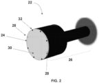
- FIG. 2 illustrates the assembled configuration of the patella reamer illustrated in FIG. 1 therein providing a cutting instrument 22 having a cutting component 24 and a driver component 26.
- the two axial-bearing bosses 28 (white) which are directly opposed to one another on the circular cutting component 24, are flush to the surface 30 of the cutting component 24 after the heat staking procedure.
- the six torque bearing bosses 32 (black) are originally designed to be flush to the cutting surface 30. Accordingly, in this particular preferred example, there are two axial bearing bosses heat-staked to the cutting component, six torque-bearing bosses that are releasably engaged to cutting component 24, and the total number of bosses is eight.
- the axial-bearing bosses 32 are present to transfer torque from the driver component 26 to the cutting component 24, the axial-bearing bosses also serve to transfer torque, but since they preferably made from a relatively lower melting material than the torque-bearing bosses, with a relatively lower flexural modulus, their ability to transfer torque is not as efficient as the torque-bearing bosses.
- the axial-bearing bosses are therefore made from a temperature sensitive material that will soften and flow during a steam-sterilization protocol such that they no longer remain engaged to the cutting component to prevent reuse of the cutting instrument. Or, stated another way, the axial-bearing bosses are such that upon exposure to steam-sterilization, they convert to a form that will not allow for engagement of the driver component 26 to the cutting component 24. This in turn will provide that the cutting instrument will not be reused and will be limited to a single use since after steam sterilization, the instrument will not function for a selected cutting procedure as the cutting component 24 will not be secured to the driver 26.
- the axial-bearing bosses herein which as noted soften and flow during steam sterilization, may be understood as providing a reuse inhibiting feature since after steam sterilization, such bosses will no longer engage with the cutting component and assume any axial load and will render the instrument inoperable.
- This in turn will eliminate the risks to patients of having a dull and potentially unsanitary cutting instrument otherwise suitable for an orthopedic procedure.
- the surgeon will now receive a cutting instrument herein in a clean and sterile form limited to a one-time use. The surgeon is assured that such instrument will therefore be sharp and suitable for resurfacing of bone material.
- the steam sterilization protocol herein is one in which the device will be exposed to steam and temperatures of preferably 121 °C to 134 °C for a time of 3 minutes to 15 minutes, that is best accomplished in an autoclave.
- the axial-bearing bosses are made from a polymeric material that indicates a melting temperature (Tm) of less than 121 °C, or in the range of 60 °C to less than 121 °C.
- Tm melting temperature
- Such polymeric material is also one that preferably indicates a melt flow index (MFI) in the range of 5-500, more preferably 25-500. Melt flow index is conveniently determined according to ISO standard 1133-1 (12-1-2011).
- both the axial-bearing bosses and torque-bearing bosses herein are such that they may both be capable of undergoing alternative sterilization procedures prior to initial use of the cutting instruments herein. This would include, but is not limited to sterilization by exposure to gamma radiation or ethylene oxide (ETO) sterilization protocols.
- ETO ethylene oxide
- the axial-bearing bosses are sourced from polycarprolactone, which is available under the trade name CAPA TM and identified as a thermoplastic material available from Perstorp with a reported melting point of around 60 °C.
- the axial-bearing bosses may also be preferably made from an ethylene-co-vinyl-acetate polymer, under the trade name ELVAX TM available from DuPont, with a reported melting point of around 87 °C. More specifically, ELVAX TM 250 with a melt flow index of 25, ELVAX TM 410 with a melt flow index of 500 and ELVAX 420 with a melt flow index of 150.
- FIG. 3 illustrates another example of a cutting instrument in the context of the present invention. More specifically, FIG. 3 identifies an unassembled acetabular reaming instrument having a driver assembly 34 and a cutting component 36.
- the cutting component may have a hemispherical type cutting surface 37. Again, for clarity, the cutting edges are not shown on the cutting component.
- the driver again is configured to have standing bosses 38 that extend from the surface 40 of the driver and are designed to be located in corresponding holes 42 on the cutting component 36.
- the holes on the cutting component are provided in the form of tab 43 that may be attached to the cutting component 36 or such tabs may be part of and extend directly from the cutting component 36.
- the standing bosses 38 which may all be axial-bearing bosses, are shown as a pair of standing bosses located at what may be described as the 0°, 90°, 180° and 270° location about the circular perimeter of the driver assembly 34.
- the bosses may be preferably disposed as such relative angular locations, or at only the 0° and 180° location, or only at the 90° and 270° location.
- the bosses herein are utilized, such bosses may be placed at the 0°, 120° and 240° locations.
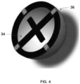
- FIG. 4 which illustrates the assembly of the unassembled acetabular reaming instrument shown in FIG. 3 wherein the driver assembly 34 and a cutting component 36 are jointed and the axial-bearing bosses have been heat-staked to the cutting component.
- the driver assembly 34 and a cutting component 36 are jointed and the axial-bearing bosses have been heat-staked to the cutting component.
- one or more of the axial-bearing bosses may be replaced with a torque-bearing boss.
- the use of the axial-bearing bosses alone, or in combination with the torque-bearing bosses, are such that they preferably provide the ability to support a torque load, as between the driver and the rotational cutting surface, in the range of 1Nm to 40 Nm, more preferably in the range of 5 Nm to 20Nm.
Landscapes
- Health & Medical Sciences (AREA)
- Life Sciences & Earth Sciences (AREA)
- Surgery (AREA)
- Engineering & Computer Science (AREA)
- Medical Informatics (AREA)
- General Health & Medical Sciences (AREA)
- Veterinary Medicine (AREA)
- Public Health (AREA)
- Biomedical Technology (AREA)
- Heart & Thoracic Surgery (AREA)
- Nuclear Medicine, Radiotherapy & Molecular Imaging (AREA)
- Molecular Biology (AREA)
- Animal Behavior & Ethology (AREA)
- Dentistry (AREA)
- Oral & Maxillofacial Surgery (AREA)
- Orthopedic Medicine & Surgery (AREA)
- Mechanical Engineering (AREA)
- Surgical Instruments (AREA)
- Physics & Mathematics (AREA)
- Biophysics (AREA)
- Optics & Photonics (AREA)
- Pathology (AREA)
- Radiology & Medical Imaging (AREA)
Description
- The present invention is directed at a thermally sensitive retention mechanism for orthopedic cutting instruments. More specifically, the present invention incorporates structural engagement features into a rotational orthopedic cutting instrument that transfers torque from a driver to a cutting component and which upon heating result in disengagement of the cutting component from the driver portion.
- There have been a variety of reported efforts to provide a disposable medical device with a design that prevents the medical device from being utilized a second time. For example,
U.S. Patent No. 5,569,163 entitled Disposable Surgical Instrument discloses the use of a lens mounting element molded from a material such as a natural or synthetic polymer which is capable of deforming in the presence of a deforming agent such as water, organic solvent, heat, gas, or light.U.S. Patent No. 5,779,686 is entitled Disposable Medical Instrument and discloses a medical instrument which cannot be reused if it is washed after use, or which makes it possible to judge whether the medical instrument has been washed thereby precluding reuse.U.S. Patent No. 6,869,392 is entitled Disposable Implement Inserted Into An Endoscope and discloses the use of a disposable implement insertable into an endoscope and comprising at least one zone matched to the shape of the endoscope that is designed to be permanently deformed on account of having been used a first time by the inevitable mechanical, thermal and/or chemical treatment it undergoes in the endoscope.U.S. Patent No. 8,383,804 is entitled Prevention Of Reuse Of A Medical Device and discloses the use of a clamp that has an element that alters its appearance while being heated over a threshold temperature, thus giving optical or mechanical information that the device should not be used a second time.U.S. Publ. No. 2009/00655565 WO98/37819
Further prior art is disclosed in documentsUS 2015/066030 A1 andWO 2015/070159 A1 .US 2015/066030 A1 discloses a cutting instrument according to the preamble ofclaims 1 and 15. - Accordingly, there exists a continuing need for surgical instrument designs that will prevent re-use of the instrument, and in particular, re-use of orthopedic cutting instruments, which would then reduce the problems associated with cleanliness and sterility of patients undergoing orthopedic procedures in which articular surfaces are removed, resurfaced and prepared to receive an implant.
- A cutting instrument comprising a driver component adapted to provide a rotating torque motion including an end portion containing one or a plurality of axial-bearing bosses and optionally one or a plurality of torque-bearing bosses and a cutting component including one or a plurality of holes to engage with said axial bearing bosses and said optional torque-bearing bosses. The axial-bearing bosses comprise a temperature sensitive material which upon exposure to steam sterilization do not allow for engagement of said axial-bearing bosses with said cutting component to thereby prevent reuse of the cutting instrument.
- In related embodiment the present invention relates to a cutting instrument comprising: a driver component adapted to provide a rotating torque motion including an end portion containing: (i) one or a plurality of axial-bearing bosses having a height in the range of 1.0 mm to 4.0 mm and a diameter of 0.25 mm to 4.0 mm, and (ii) one or a plurality of torque-bearing bosses having a height in the range of 1.0 mm to 4.0 mm and a diameter of 0.25 mm to 4.0 mm. The cutting instrument also includes a cutting component including one or a plurality of holes to engage with said axial bearing bosses and said optional torque-bearing bosses. The axial-bearing bosses comprise a temperature sensitive material which upon exposure to steam sterilization do not allow for engagement of said axial-bearing bosses with said cutting component to thereby prevent reuse of the cutting instrument.
- In method form, the present invention relates to a method for preventing reuse of an orthopedic cutting instrument comprising: providing a driver component adapted to provide a rotating torque motion including an end portion containing one or a plurality of axial-bearing bosses and optionally one or a plurality of torque-bearing bosses. One then provides a cutting component including one or a plurality of holes to engage with said axial bearing bosses and said optional torque-bearing bosses. This is followed by engaging said axial-bearing bosses to said cutting component wherein said axial-bearing bosses comprise a temperature sensitive material which upon exposure to steam sterilization disengage from said cutting component to thereby prevent reuse of the cutting instrument.
- The invention can be best understood by reference to the following detailed description of the preferred embodiments when considered in conjunction with the accompany drawings wherein:
-
FIG. 1 illustrates an example of the present invention in the form of an unassembled patella reaming instrument. -
FIG. 2 illustrates the assembled configuration of the patella reamer illustrated inFIG. 1 . -
FIG. 3 illustrates another example of the present invention in the form of an unassembled acetabular reaming instrument. -
FIG. 4 , illustrates the assembly of the unassembled acetabular reaming instrument shown inFIG. 3 . - With attention directed to
FIG. 1 , the present invention is illustrated in the form of an unassembled patella reaming instrument having acutting component 10 that has the indicatedholes 12 preferably along theperimeter 11 of the component. Preferably, the holes are positioned such that they are within 1-10 mm of theperimeter 11. Also shown isdriver interface component 14 which has standingbosses 16. The standing bosses are positioned on anend portion 15 such that they will align with theholes 12 on thecutting component 10. The driver interface component is adapted to provide a rotating torque motion to thecutting component 10. For clarity, the cutting edges are not shown on the cutting component. Reference to a standingboss 16 may be understood as a protruding feature from a surface of the driver that is intended to be located in thecorresponding holes 12. In the broad context of the present invention the total number of standing bosses may preferably fall in the range of 1-10, with a height preferably in the range of 1.0 mm to 4.0 mm, more preferably 2.0 mm to 3.0 mm, and most preferably, a height of 2.5 mm with a +/- 0.1 mm tolerance. The standing bosses also may be of any geometrical shape but are preferably round or oval. The standing bosses preferably have a diameter of 0.25 mm to 4.0 mm, most preferably 1.5 mm to 3.5 mm, and in an even more preferred embodiment, a diameter of 2.0 mm at a +/- 0.1 mm tolerance. - The standing bosses are preferably of two types and formed from two different materials. That is, a first material which defines the bosses as torque-bearing bosses and a second material that defines the bosses as axial-bearing bosses. The torque bearing bosses are preferably made to protrude and releasably engage through
holes 12 and are capable of transferring torque from thedriver interface 14 to thecutting component 10. It should be noted that the torque-bearing bosses are optional, in the sense that it is contemplated herein that the only bosses necessary are the axial-bearing bosses, further described herein. However, to the extent that torque-bearing bosses are utilized, they are preferably present at a level of 1 torque-bearing boss to a plurality of torque bearing bosses, more preferably up to and including 9 torque-bearing bosses. The corresponding number of axial-bearing bosses are preferably present at a minimum level of 1 axial-bearing boss to a plurality of axial bearing bosses, more preferably up to 9 axial bearing bosses. This in turn provide that the total number of bosses, as noted above, is preferably in the range of 1-10 bosses. - The torque-bearing bosses that are releasably engaged in through-
holes 12 are preferably made of material that does not soften during steam sterilization, as described herein. Accordingly, the torque-bearing bosses are such that they preferably maintain their torque-bearing ability following steam sterilization. Preferred materials for the torque-bearing bosses include both polymeric material and/or metallic material. Polymer material preferably includes polysulfones, such as polyphenylsulfone sold under the tradename Radel® R-5100, available from Solvay. In addition, the torque-bearing bosses may be made from a polyarylamide sold under the tradename Ixef® HC-1022 also available from Solvay. - The axial-bearing bosses are to be understood as mechanical engaging with the driver and which serve to releasable secure the driver to the cutting component. More specifically, the axial-bearing bosses secure the cutting component to the driver and reduce or prevent movement along the axial or
longitudinal axis 18 during a given cutting procedure. Preferably, when the cutting component is assembled to the driver, the axial-bearing bosses are heat-staked such that the boss material melts flush to thesurface 20 of the cutting component or below the cutting surface. Heat staking is reference to the general procedure where thebosses 16 are positioned inholes 12 and the bosses are then deformed with heating which mechanical engages thedriver 14 to thecutting component 10. Other contemplated procedures for engaging the axial-bearing bosses to the driver include exposure of the bosses to ultrasonic welding or swaging. Swaging is reference to cold-forming of the axial-bearing boss to the cutting component such that the axial bearing boss is again flush to the surface of the cutting component after joining. - Attention is directed to
FIG. 2 which illustrates the assembled configuration of the patella reamer illustrated inFIG. 1 therein providing acutting instrument 22 having acutting component 24 and adriver component 26. As can be seen, after heat-staking, the two axial-bearing bosses 28 (white) which are directly opposed to one another on thecircular cutting component 24, are flush to thesurface 30 of thecutting component 24 after the heat staking procedure. Meanwhile, the six torque bearing bosses 32 (black) are originally designed to be flush to thecutting surface 30. Accordingly, in this particular preferred example, there are two axial bearing bosses heat-staked to the cutting component, six torque-bearing bosses that are releasably engaged to cuttingcomponent 24, and the total number of bosses is eight. It should be appreciated that while the torque-bearingbosses 32 are present to transfer torque from thedriver component 26 to thecutting component 24, the axial-bearing bosses also serve to transfer torque, but since they preferably made from a relatively lower melting material than the torque-bearing bosses, with a relatively lower flexural modulus, their ability to transfer torque is not as efficient as the torque-bearing bosses. - The axial-bearing bosses are therefore made from a temperature sensitive material that will soften and flow during a steam-sterilization protocol such that they no longer remain engaged to the cutting component to prevent reuse of the cutting instrument. Or, stated another way, the axial-bearing bosses are such that upon exposure to steam-sterilization, they convert to a form that will not allow for engagement of the
driver component 26 to thecutting component 24. This in turn will provide that the cutting instrument will not be reused and will be limited to a single use since after steam sterilization, the instrument will not function for a selected cutting procedure as the cuttingcomponent 24 will not be secured to thedriver 26. Accordingly, the axial-bearing bosses herein, which as noted soften and flow during steam sterilization, may be understood as providing a reuse inhibiting feature since after steam sterilization, such bosses will no longer engage with the cutting component and assume any axial load and will render the instrument inoperable. This in turn will eliminate the risks to patients of having a dull and potentially unsanitary cutting instrument otherwise suitable for an orthopedic procedure. Stated another way, the surgeon will now receive a cutting instrument herein in a clean and sterile form limited to a one-time use. The surgeon is assured that such instrument will therefore be sharp and suitable for resurfacing of bone material. Once the surgery is complete, the process utilized by hospitals to clean and sterilize the instrument (i.e. steam sterilization) will, as noted, render the instrument unworkable and prevent the surgeon from using the instrument on a second patient. - The steam sterilization protocol herein is one in which the device will be exposed to steam and temperatures of preferably 121 °C to 134 °C for a time of 3 minutes to 15 minutes, that is best accomplished in an autoclave. Preferably, the axial-bearing bosses are made from a polymeric material that indicates a melting temperature (Tm) of less than 121 °C, or in the range of 60 °C to less than 121 °C. Such polymeric material is also one that preferably indicates a melt flow index (MFI) in the range of 5-500, more preferably 25-500. Melt flow index is conveniently determined according to ISO standard 1133-1 (12-1-2011). Accordingly, upon exposure to such steam-sterilization, as noted above, the axial-bearing bosses will soften as flow. However, it is useful to note that both the axial-bearing bosses and torque-bearing bosses herein are such that they may both be capable of undergoing alternative sterilization procedures prior to initial use of the cutting instruments herein. This would include, but is not limited to sterilization by exposure to gamma radiation or ethylene oxide (ETO) sterilization protocols.
- Preferably, the axial-bearing bosses are sourced from polycarprolactone, which is available under the trade name CAPA™ and identified as a thermoplastic material available from Perstorp with a reported melting point of around 60 °C. The axial-bearing bosses may also be preferably made from an ethylene-co-vinyl-acetate polymer, under the trade name ELVAX™ available from DuPont, with a reported melting point of around 87 °C. More specifically, ELVAX™ 250 with a melt flow index of 25, ELVAX™ 410 with a melt flow index of 500 and ELVAX 420 with a melt flow index of 150.
- Attention is next directed to
FIG. 3 , which illustrates another example of a cutting instrument in the context of the present invention. More specifically,FIG. 3 identifies an unassembled acetabular reaming instrument having adriver assembly 34 and acutting component 36. The cutting component may have a hemisphericaltype cutting surface 37. Again, for clarity, the cutting edges are not shown on the cutting component. The driver again is configured to have standingbosses 38 that extend from thesurface 40 of the driver and are designed to be located in correspondingholes 42 on thecutting component 36. In addition, as can be seen, the holes on the cutting component are provided in the form oftab 43 that may be attached to thecutting component 36 or such tabs may be part of and extend directly from the cuttingcomponent 36. - As can be seen in this exemplary embodiment, the standing
bosses 38, which may all be axial-bearing bosses, are shown as a pair of standing bosses located at what may be described as the 0°, 90°, 180° and 270° location about the circular perimeter of thedriver assembly 34. It should therefore be appreciated that in the broad context of the present invention, with respect to a driver having a generally circular configuration, the bosses may be preferably disposed as such relative angular locations, or at only the 0° and 180° location, or only at the 90° and 270° location. Alternatively, if three (3) the bosses herein are utilized, such bosses may be placed at the 0°, 120° and 240° locations. Finally, attention is directed toFIG. 4 , which illustrates the assembly of the unassembled acetabular reaming instrument shown inFIG. 3 wherein thedriver assembly 34 and acutting component 36 are jointed and the axial-bearing bosses have been heat-staked to the cutting component. Although not shown, one or more of the axial-bearing bosses may be replaced with a torque-bearing boss. - With regards to the standing bosses herein, it should be noted that the use of the axial-bearing bosses alone, or in combination with the torque-bearing bosses, are such that they preferably provide the ability to support a torque load, as between the driver and the rotational cutting surface, in the range of 1Nm to 40 Nm, more preferably in the range of 5 Nm to 20Nm. In addition, it should now be appreciated that the use of the coupling system herein that relies upon the axial-bearing bosses, either alone or in combination with the torque-bearing bosses, may be used to couple a driver providing a rotary motion to a rotatory cutting component, in an orthopedic reamer, such as in the above exemplary patella reamer design or acetabular reaming instrument. However, in the broad context of the present invention, such bosses may be utilized in glenoid reamers, intramedullary reamers or calcar reamers.
Claims (16)
- A cutting instrument (22) comprising:a driver component (26) adapted to provide a rotating torque motion including an end portion containing one or a plurality of axial-bearing bosses (28) and optionally one or a plurality of torque-bearing bosses (32);a cutting component (24) including one or a plurality of holes to engage with said axial bearing bosses and said optional torque-bearing bosses;characterized in that said axial-bearing bosses comprise a temperature sensitive material which upon exposure to steam sterilization do not allow for engagement of said axial-bearing bosses with said cutting component to thereby prevent reuse of the cutting instrument.
- The cutting instrument of claim 1 wherein the number of axial-bearing bosses is 1-9.
- The cutting instrument of claim 1 wherein said axial-bearing bosses have a height in the range of 1.0 mm to 4.0 mm and a diameter of 0.25 mm to 4.0 mm.
- The cutting instrument of claim 1 wherein said axial-bearing bosses are made from a polymeric material having a melt flow index of 5-500.
- The cutting instrument of claim 1 wherein said axial-bearing bosses have a melting temperature of less than 121 °C and preferably have a melting point in the range of 60 °C to less than 121 °C.
- The cutting instrument of claim 1 wherein said driver component provides a rotating torque motion to said cutting component comprising a torque load of 1Nm to 40Nm.
- The cutting instrument of claim 1 further including one or a plurality of torque-bearing bosses.
- The cutting instrument of claim 1 wherein said instrument comprises a patella reamer, an acetabular reaming instrument, a glenoid reamer, an intramedullary reamer or a calcar reamer.
- The cutting instrument of claim 1 characterized in that the driver component is adapted to provide a rotating torque motion including an end portion containing: (i) one or a plurality of axial-bearing bosses having a height in the range of 1.0 mm to 4.0 mm and a diameter of 0.25 mm to 4.0 mm, and (ii) one or a plurality of torque-bearing bosses, having a height in the range of 1.0 mm to 4.0 mm and a diameter of 0.25 mm to 4.0 mm.
- The cutting instrument of claim 9 wherein the number of axial-bearing bosses is 1-9.
- The cutting instrument of claim 9 wherein said axial-bearing bosses are made from a polymeric material having a melt flow index of 5-500.
- The cutting instrument of claim 9 wherein said axial-bearing bosses have a melting temperature of less than 121 °C, preferably said axial-bearing bosses having a melting point in the range of 60 °C to less than 121 °C.
- The cutting instrument of claim 9 wherein said driver component provides a rotating torque motion to said cutting component comprising a torque load of 1Nm to 40Nm.
- The cutting instrument of claim 9 wherein said instrument comprises a patella reamer, an acetabular reaming instrument, a glenoid reamer, an intramedullary reamer or a calcar reamer.
- A method for preventing reuse of an orthopedic cutting instrument comprising:providing a driver component (26) adapted to provide a rotating torque motion including an end portion containing one or a plurality of axial-bearing bosses (28), and optionally one or a plurality of torque-bearing bosses (32),providing a cutting component (24) including one or a plurality of holes to engage with said axial bearing bosses and said optional torque-bearing bosses;engaging said axial bearing bosses to said cutting component characterized in that said axial-bearing bosses comprise a temperature sensitive material which upon exposure to steam sterilization disengage from said cutting component to thereby prevent reuse of the cutting instrument.
- The method of claim 15 characterized by the use of one or more axial-bearing bosses having one or several features according to anyone of the preceding claims 2 to 8.
Applications Claiming Priority (2)
| Application Number | Priority Date | Filing Date | Title |
|---|---|---|---|
| US201762609469P | 2017-12-22 | 2017-12-22 | |
| PCT/US2018/067446 WO2019126825A1 (en) | 2017-12-22 | 2018-12-24 | Thermally sensitive retention mechanism for orthopedic cutting instruments |
Publications (3)
| Publication Number | Publication Date |
|---|---|
| EP3727160A1 EP3727160A1 (en) | 2020-10-28 |
| EP3727160A4 EP3727160A4 (en) | 2021-09-08 |
| EP3727160B1 true EP3727160B1 (en) | 2023-11-29 |
Family
ID=66949749
Family Applications (1)
| Application Number | Title | Priority Date | Filing Date |
|---|---|---|---|
| EP18890196.1A Active EP3727160B1 (en) | 2017-12-22 | 2018-12-24 | Thermally sensitive retention mechanism for orthopedic cutting instruments |
Country Status (3)
| Country | Link |
|---|---|
| US (1) | US11696769B2 (en) |
| EP (1) | EP3727160B1 (en) |
| WO (1) | WO2019126825A1 (en) |
Family Cites Families (23)
| Publication number | Priority date | Publication date | Assignee | Title |
|---|---|---|---|---|
| US4456010A (en) * | 1980-10-27 | 1984-06-26 | Codman & Shurtleff, Inc. | Cranial drill |
| US4951690A (en) * | 1984-01-31 | 1990-08-28 | Baker John W | Method of drilling through a bone structure |
| US5295992A (en) * | 1992-03-16 | 1994-03-22 | Othy, Inc. | Patella cutting system |
| JPH0795982A (en) | 1993-04-19 | 1995-04-11 | Olympus Optical Co Ltd | Disposable medical device |
| US5569163A (en) | 1994-09-14 | 1996-10-29 | United States Surgical Corporation | Disposable surgical instrument |
| JP2000509636A (en) | 1997-02-28 | 2000-08-02 | エチコン・エンド―サージエリー・インコーポレーテツド | Non-reusable surgical device |
| US20020165549A1 (en) * | 2001-04-30 | 2002-11-07 | Medtronic, Inc. | Surgical instrument and attachment |
| DE10216928B4 (en) | 2002-04-17 | 2004-07-15 | Olympus Winter & Ibe Gmbh | Disposable instrument that can be used in an endoscope |
| FR2847453B1 (en) * | 2002-11-22 | 2005-09-23 | Jean Francois Biegun | ANCILLARIES, ESPECIALLY RAPE OR CUTTING BLOCK, FOR SINGLE USE, KIT COMPRISING ANCILLARIES AND METHOD OF MANUFACTURE |
| ES2471948T3 (en) | 2006-10-13 | 2014-06-27 | Stryker Trauma Sa | Prevention of reuse of a medical device |
| US8460297B2 (en) * | 2007-01-05 | 2013-06-11 | Biomet 3I, Llc | Drill bit assembly for bone tissue including depth limiting feature |
| US20090065565A1 (en) | 2007-09-12 | 2009-03-12 | Vascular Technologies, Inc. | System, method and apparatus for preventing reuse of medical instruments |
| EP2359755B1 (en) * | 2010-02-12 | 2014-01-15 | Greatbatch Ltd. | Disposable reamer |
| EP2478852B1 (en) * | 2011-01-21 | 2017-10-18 | Greatbatch Ltd. | Disposable surgical hemispherical cutter for convex or concave surfaces |
| EP2747682A4 (en) * | 2011-08-23 | 2015-01-21 | Flexmedex Llc | Tissue removal device and method |
| US20130204254A1 (en) | 2012-02-07 | 2013-08-08 | Biomet Manufacturing Corporation | Limited Use Acetabular Reamer |
| US9370372B2 (en) * | 2013-09-04 | 2016-06-21 | Mcginley Engineered Solutions, Llc | Drill bit penetration measurement systems and methods |
| WO2015070159A1 (en) * | 2013-11-08 | 2015-05-14 | Mcginley Engineered Solutions, Llc. | Surgical saw with sensing technology for determining cut through of bone and depth of the saw blade during surgery |
| US10092304B2 (en) * | 2014-09-30 | 2018-10-09 | Depuy Ireland Unlimited Company | Orthopaedic surgical instrument assembly for reaming a patient's acetabulum |
| US11298434B2 (en) * | 2015-07-09 | 2022-04-12 | Misonix, Incorporated | Ultrasonic medical probe with failsafe for sterility and associated method |
| US10335170B2 (en) * | 2016-02-12 | 2019-07-02 | Viant As&O Holdings, Llc | Cutting heads for intramedullary reamers |
| US10555725B2 (en) * | 2016-09-29 | 2020-02-11 | Gyrus Acmi, Inc. | Thermal mechanism to prevent reprocessing or reuse of mechanical surgical devices |
| US20230000582A1 (en) * | 2021-07-01 | 2023-01-05 | Mainstream Medical Devices, LLC | Autoclave self-destructing medical devices |
-
2018
- 2018-12-21 US US16/230,520 patent/US11696769B2/en active Active
- 2018-12-24 EP EP18890196.1A patent/EP3727160B1/en active Active
- 2018-12-24 WO PCT/US2018/067446 patent/WO2019126825A1/en not_active Ceased
Also Published As
| Publication number | Publication date |
|---|---|
| US20190192171A1 (en) | 2019-06-27 |
| EP3727160A4 (en) | 2021-09-08 |
| EP3727160A1 (en) | 2020-10-28 |
| WO2019126825A1 (en) | 2019-06-27 |
| US11696769B2 (en) | 2023-07-11 |
Similar Documents
| Publication | Publication Date | Title |
|---|---|---|
| US12318096B2 (en) | Screw guide and tissue retractor instrument | |
| JP5256027B2 (en) | Protective cap for arthroscopic instruments | |
| US6648223B2 (en) | Surgical system | |
| US9204920B2 (en) | External reader for device management | |
| US5924206A (en) | Reusable device handle | |
| JP5964545B2 (en) | Apparatus and method for use in ligament regenerative surgery | |
| US9326785B2 (en) | Connector for a laparoscopic surgical system | |
| US20020165549A1 (en) | Surgical instrument and attachment | |
| US20090318922A9 (en) | Reamer spindle for minimally invasive joint surgery | |
| WO2010064050A1 (en) | Surgical instrument, handle for a surgical instrument and surgical instrument system | |
| CN102016883A (en) | Medical device tracking system with tag and method | |
| WO2001067970A1 (en) | Orthopedic medical device | |
| EP2192862A1 (en) | Dual reamer driver | |
| US8439920B2 (en) | Adapter for a surgical reamer driver | |
| EP1384132B1 (en) | Surgical system | |
| US20200093555A1 (en) | Systems and tools for use with surgical robotic manipulators | |
| US20200069317A1 (en) | Tool for cutting bone for surgical use | |
| JP2014069081A (en) | Surgical instrument and method of use | |
| US11696769B2 (en) | Thermally sensitive retention mechanism for orthopedic cutting instruments | |
| US6869392B2 (en) | Disposable implement inserted into an endoscope | |
| US20230000582A1 (en) | Autoclave self-destructing medical devices | |
| CN114098889B (en) | Retractable into the bone to enter the system | |
| US8497129B2 (en) | Reprocessing indicators for medical instruments | |
| JP6208149B2 (en) | Implant fixing member holder | |
| Stulberg | The rationale for using computer navigation with minimally invasive THA |
Legal Events
| Date | Code | Title | Description |
|---|---|---|---|
| STAA | Information on the status of an ep patent application or granted ep patent |
Free format text: STATUS: THE INTERNATIONAL PUBLICATION HAS BEEN MADE |
|
| PUAI | Public reference made under article 153(3) epc to a published international application that has entered the european phase |
Free format text: ORIGINAL CODE: 0009012 |
|
| STAA | Information on the status of an ep patent application or granted ep patent |
Free format text: STATUS: REQUEST FOR EXAMINATION WAS MADE |
|
| 17P | Request for examination filed |
Effective date: 20200622 |
|
| AK | Designated contracting states |
Kind code of ref document: A1 Designated state(s): AL AT BE BG CH CY CZ DE DK EE ES FI FR GB GR HR HU IE IS IT LI LT LU LV MC MK MT NL NO PL PT RO RS SE SI SK SM TR |
|
| AX | Request for extension of the european patent |
Extension state: BA ME |
|
| DAV | Request for validation of the european patent (deleted) | ||
| DAX | Request for extension of the european patent (deleted) | ||
| A4 | Supplementary search report drawn up and despatched |
Effective date: 20210805 |
|
| RIC1 | Information provided on ipc code assigned before grant |
Ipc: A61B 1/00 20060101ALN20210730BHEP Ipc: A61B 90/00 20160101ALN20210730BHEP Ipc: A61B 17/00 20060101ALN20210730BHEP Ipc: A61B 17/16 20060101AFI20210730BHEP |
|
| REG | Reference to a national code |
Ref country code: DE Ref legal event code: R079 Free format text: PREVIOUS MAIN CLASS: A61B0017000000 Ipc: A61B0017160000 Ref country code: DE Ref legal event code: R079 Ref document number: 602018062020 Country of ref document: DE Free format text: PREVIOUS MAIN CLASS: A61B0017000000 Ipc: A61B0017160000 |
|
| GRAP | Despatch of communication of intention to grant a patent |
Free format text: ORIGINAL CODE: EPIDOSNIGR1 |
|
| STAA | Information on the status of an ep patent application or granted ep patent |
Free format text: STATUS: GRANT OF PATENT IS INTENDED |
|
| RIC1 | Information provided on ipc code assigned before grant |
Ipc: A61B 1/00 20060101ALN20230515BHEP Ipc: A61B 90/00 20160101ALN20230515BHEP Ipc: A61B 17/00 20060101ALN20230515BHEP Ipc: A61B 17/16 20060101AFI20230515BHEP |
|
| RIC1 | Information provided on ipc code assigned before grant |
Ipc: A61B 1/00 20060101ALN20230522BHEP Ipc: A61B 90/00 20160101ALN20230522BHEP Ipc: A61B 17/00 20060101ALN20230522BHEP Ipc: A61B 17/16 20060101AFI20230522BHEP |
|
| INTG | Intention to grant announced |
Effective date: 20230619 |
|
| GRAS | Grant fee paid |
Free format text: ORIGINAL CODE: EPIDOSNIGR3 |
|
| GRAA | (expected) grant |
Free format text: ORIGINAL CODE: 0009210 |
|
| STAA | Information on the status of an ep patent application or granted ep patent |
Free format text: STATUS: THE PATENT HAS BEEN GRANTED |
|
| AK | Designated contracting states |
Kind code of ref document: B1 Designated state(s): AL AT BE BG CH CY CZ DE DK EE ES FI FR GB GR HR HU IE IS IT LI LT LU LV MC MK MT NL NO PL PT RO RS SE SI SK SM TR |
|
| REG | Reference to a national code |
Ref country code: GB Ref legal event code: FG4D |
|
| REG | Reference to a national code |
Ref country code: CH Ref legal event code: EP |
|
| REG | Reference to a national code |
Ref country code: DE Ref legal event code: R096 Ref document number: 602018062020 Country of ref document: DE |
|
| REG | Reference to a national code |
Ref country code: IE Ref legal event code: FG4D |
|
| REG | Reference to a national code |
Ref country code: DE Ref legal event code: R082 Ref document number: 602018062020 Country of ref document: DE Representative=s name: LIPPERT STACHOW PATENTANWAELTE RECHTSANWAELTE , DE |
|
| REG | Reference to a national code |
Ref country code: LT Ref legal event code: MG9D |
|
| REG | Reference to a national code |
Ref country code: NL Ref legal event code: MP Effective date: 20231129 |
|
| PG25 | Lapsed in a contracting state [announced via postgrant information from national office to epo] |
Ref country code: GR Free format text: LAPSE BECAUSE OF FAILURE TO SUBMIT A TRANSLATION OF THE DESCRIPTION OR TO PAY THE FEE WITHIN THE PRESCRIBED TIME-LIMIT Effective date: 20240301 |
|
| PG25 | Lapsed in a contracting state [announced via postgrant information from national office to epo] |
Ref country code: IS Free format text: LAPSE BECAUSE OF FAILURE TO SUBMIT A TRANSLATION OF THE DESCRIPTION OR TO PAY THE FEE WITHIN THE PRESCRIBED TIME-LIMIT Effective date: 20240329 |
|
| PG25 | Lapsed in a contracting state [announced via postgrant information from national office to epo] |
Ref country code: LT Free format text: LAPSE BECAUSE OF FAILURE TO SUBMIT A TRANSLATION OF THE DESCRIPTION OR TO PAY THE FEE WITHIN THE PRESCRIBED TIME-LIMIT Effective date: 20231129 |
|
| PG25 | Lapsed in a contracting state [announced via postgrant information from national office to epo] |
Ref country code: ES Free format text: LAPSE BECAUSE OF FAILURE TO SUBMIT A TRANSLATION OF THE DESCRIPTION OR TO PAY THE FEE WITHIN THE PRESCRIBED TIME-LIMIT Effective date: 20231129 |
|
| PG25 | Lapsed in a contracting state [announced via postgrant information from national office to epo] |
Ref country code: LT Free format text: LAPSE BECAUSE OF FAILURE TO SUBMIT A TRANSLATION OF THE DESCRIPTION OR TO PAY THE FEE WITHIN THE PRESCRIBED TIME-LIMIT Effective date: 20231129 Ref country code: IS Free format text: LAPSE BECAUSE OF FAILURE TO SUBMIT A TRANSLATION OF THE DESCRIPTION OR TO PAY THE FEE WITHIN THE PRESCRIBED TIME-LIMIT Effective date: 20240329 Ref country code: GR Free format text: LAPSE BECAUSE OF FAILURE TO SUBMIT A TRANSLATION OF THE DESCRIPTION OR TO PAY THE FEE WITHIN THE PRESCRIBED TIME-LIMIT Effective date: 20240301 Ref country code: ES Free format text: LAPSE BECAUSE OF FAILURE TO SUBMIT A TRANSLATION OF THE DESCRIPTION OR TO PAY THE FEE WITHIN THE PRESCRIBED TIME-LIMIT Effective date: 20231129 Ref country code: BG Free format text: LAPSE BECAUSE OF FAILURE TO SUBMIT A TRANSLATION OF THE DESCRIPTION OR TO PAY THE FEE WITHIN THE PRESCRIBED TIME-LIMIT Effective date: 20240229 |
|
| REG | Reference to a national code |
Ref country code: AT Ref legal event code: MK05 Ref document number: 1635282 Country of ref document: AT Kind code of ref document: T Effective date: 20231129 |
|
| PG25 | Lapsed in a contracting state [announced via postgrant information from national office to epo] |
Ref country code: NL Free format text: LAPSE BECAUSE OF FAILURE TO SUBMIT A TRANSLATION OF THE DESCRIPTION OR TO PAY THE FEE WITHIN THE PRESCRIBED TIME-LIMIT Effective date: 20231129 |
|
| PG25 | Lapsed in a contracting state [announced via postgrant information from national office to epo] |
Ref country code: SE Free format text: LAPSE BECAUSE OF FAILURE TO SUBMIT A TRANSLATION OF THE DESCRIPTION OR TO PAY THE FEE WITHIN THE PRESCRIBED TIME-LIMIT Effective date: 20231129 Ref country code: RS Free format text: LAPSE BECAUSE OF FAILURE TO SUBMIT A TRANSLATION OF THE DESCRIPTION OR TO PAY THE FEE WITHIN THE PRESCRIBED TIME-LIMIT Effective date: 20231129 Ref country code: PL Free format text: LAPSE BECAUSE OF FAILURE TO SUBMIT A TRANSLATION OF THE DESCRIPTION OR TO PAY THE FEE WITHIN THE PRESCRIBED TIME-LIMIT Effective date: 20231129 Ref country code: NO Free format text: LAPSE BECAUSE OF FAILURE TO SUBMIT A TRANSLATION OF THE DESCRIPTION OR TO PAY THE FEE WITHIN THE PRESCRIBED TIME-LIMIT Effective date: 20240229 Ref country code: NL Free format text: LAPSE BECAUSE OF FAILURE TO SUBMIT A TRANSLATION OF THE DESCRIPTION OR TO PAY THE FEE WITHIN THE PRESCRIBED TIME-LIMIT Effective date: 20231129 Ref country code: LV Free format text: LAPSE BECAUSE OF FAILURE TO SUBMIT A TRANSLATION OF THE DESCRIPTION OR TO PAY THE FEE WITHIN THE PRESCRIBED TIME-LIMIT Effective date: 20231129 Ref country code: HR Free format text: LAPSE BECAUSE OF FAILURE TO SUBMIT A TRANSLATION OF THE DESCRIPTION OR TO PAY THE FEE WITHIN THE PRESCRIBED TIME-LIMIT Effective date: 20231129 |
|
| PG25 | Lapsed in a contracting state [announced via postgrant information from national office to epo] |
Ref country code: DK Free format text: LAPSE BECAUSE OF FAILURE TO SUBMIT A TRANSLATION OF THE DESCRIPTION OR TO PAY THE FEE WITHIN THE PRESCRIBED TIME-LIMIT Effective date: 20231129 |
|
| PG25 | Lapsed in a contracting state [announced via postgrant information from national office to epo] |
Ref country code: AT Free format text: LAPSE BECAUSE OF FAILURE TO SUBMIT A TRANSLATION OF THE DESCRIPTION OR TO PAY THE FEE WITHIN THE PRESCRIBED TIME-LIMIT Effective date: 20231129 Ref country code: CZ Free format text: LAPSE BECAUSE OF FAILURE TO SUBMIT A TRANSLATION OF THE DESCRIPTION OR TO PAY THE FEE WITHIN THE PRESCRIBED TIME-LIMIT Effective date: 20231129 |
|
| PG25 | Lapsed in a contracting state [announced via postgrant information from national office to epo] |
Ref country code: SK Free format text: LAPSE BECAUSE OF FAILURE TO SUBMIT A TRANSLATION OF THE DESCRIPTION OR TO PAY THE FEE WITHIN THE PRESCRIBED TIME-LIMIT Effective date: 20231129 |
|
| PG25 | Lapsed in a contracting state [announced via postgrant information from national office to epo] |
Ref country code: SM Free format text: LAPSE BECAUSE OF FAILURE TO SUBMIT A TRANSLATION OF THE DESCRIPTION OR TO PAY THE FEE WITHIN THE PRESCRIBED TIME-LIMIT Effective date: 20231129 Ref country code: SK Free format text: LAPSE BECAUSE OF FAILURE TO SUBMIT A TRANSLATION OF THE DESCRIPTION OR TO PAY THE FEE WITHIN THE PRESCRIBED TIME-LIMIT Effective date: 20231129 Ref country code: RO Free format text: LAPSE BECAUSE OF FAILURE TO SUBMIT A TRANSLATION OF THE DESCRIPTION OR TO PAY THE FEE WITHIN THE PRESCRIBED TIME-LIMIT Effective date: 20231129 Ref country code: IT Free format text: LAPSE BECAUSE OF FAILURE TO SUBMIT A TRANSLATION OF THE DESCRIPTION OR TO PAY THE FEE WITHIN THE PRESCRIBED TIME-LIMIT Effective date: 20231129 Ref country code: EE Free format text: LAPSE BECAUSE OF FAILURE TO SUBMIT A TRANSLATION OF THE DESCRIPTION OR TO PAY THE FEE WITHIN THE PRESCRIBED TIME-LIMIT Effective date: 20231129 Ref country code: DK Free format text: LAPSE BECAUSE OF FAILURE TO SUBMIT A TRANSLATION OF THE DESCRIPTION OR TO PAY THE FEE WITHIN THE PRESCRIBED TIME-LIMIT Effective date: 20231129 Ref country code: CZ Free format text: LAPSE BECAUSE OF FAILURE TO SUBMIT A TRANSLATION OF THE DESCRIPTION OR TO PAY THE FEE WITHIN THE PRESCRIBED TIME-LIMIT Effective date: 20231129 Ref country code: AT Free format text: LAPSE BECAUSE OF FAILURE TO SUBMIT A TRANSLATION OF THE DESCRIPTION OR TO PAY THE FEE WITHIN THE PRESCRIBED TIME-LIMIT Effective date: 20231129 |
|
| PG25 | Lapsed in a contracting state [announced via postgrant information from national office to epo] |
Ref country code: PT Free format text: LAPSE BECAUSE OF FAILURE TO SUBMIT A TRANSLATION OF THE DESCRIPTION OR TO PAY THE FEE WITHIN THE PRESCRIBED TIME-LIMIT Effective date: 20240401 |
|
| P01 | Opt-out of the competence of the unified patent court (upc) registered |
Free format text: CASE NUMBER: APP_40153/2024 Effective date: 20240705 |
|
| PG25 | Lapsed in a contracting state [announced via postgrant information from national office to epo] |
Ref country code: LU Free format text: LAPSE BECAUSE OF NON-PAYMENT OF DUE FEES Effective date: 20231224 |
|
| PG25 | Lapsed in a contracting state [announced via postgrant information from national office to epo] |
Ref country code: MC Free format text: LAPSE BECAUSE OF FAILURE TO SUBMIT A TRANSLATION OF THE DESCRIPTION OR TO PAY THE FEE WITHIN THE PRESCRIBED TIME-LIMIT Effective date: 20231129 |
|
| REG | Reference to a national code |
Ref country code: BE Ref legal event code: MM Effective date: 20231231 |
|
| PG25 | Lapsed in a contracting state [announced via postgrant information from national office to epo] |
Ref country code: PT Free format text: LAPSE BECAUSE OF FAILURE TO SUBMIT A TRANSLATION OF THE DESCRIPTION OR TO PAY THE FEE WITHIN THE PRESCRIBED TIME-LIMIT Effective date: 20240401 Ref country code: MC Free format text: LAPSE BECAUSE OF FAILURE TO SUBMIT A TRANSLATION OF THE DESCRIPTION OR TO PAY THE FEE WITHIN THE PRESCRIBED TIME-LIMIT Effective date: 20231129 Ref country code: LU Free format text: LAPSE BECAUSE OF NON-PAYMENT OF DUE FEES Effective date: 20231224 |
|
| REG | Reference to a national code |
Ref country code: DE Ref legal event code: R097 Ref document number: 602018062020 Country of ref document: DE |
|
| PLBE | No opposition filed within time limit |
Free format text: ORIGINAL CODE: 0009261 |
|
| STAA | Information on the status of an ep patent application or granted ep patent |
Free format text: STATUS: NO OPPOSITION FILED WITHIN TIME LIMIT |
|
| REG | Reference to a national code |
Ref country code: IE Ref legal event code: MM4A |
|
| PG25 | Lapsed in a contracting state [announced via postgrant information from national office to epo] |
Ref country code: IE Free format text: LAPSE BECAUSE OF NON-PAYMENT OF DUE FEES Effective date: 20231224 |
|
| PG25 | Lapsed in a contracting state [announced via postgrant information from national office to epo] |
Ref country code: BE Free format text: LAPSE BECAUSE OF NON-PAYMENT OF DUE FEES Effective date: 20231231 |
|
| PG25 | Lapsed in a contracting state [announced via postgrant information from national office to epo] |
Ref country code: SI Free format text: LAPSE BECAUSE OF FAILURE TO SUBMIT A TRANSLATION OF THE DESCRIPTION OR TO PAY THE FEE WITHIN THE PRESCRIBED TIME-LIMIT Effective date: 20231129 |
|
| PG25 | Lapsed in a contracting state [announced via postgrant information from national office to epo] |
Ref country code: SI Free format text: LAPSE BECAUSE OF FAILURE TO SUBMIT A TRANSLATION OF THE DESCRIPTION OR TO PAY THE FEE WITHIN THE PRESCRIBED TIME-LIMIT Effective date: 20231129 Ref country code: IE Free format text: LAPSE BECAUSE OF NON-PAYMENT OF DUE FEES Effective date: 20231224 Ref country code: BE Free format text: LAPSE BECAUSE OF NON-PAYMENT OF DUE FEES Effective date: 20231231 |
|
| 26N | No opposition filed |
Effective date: 20240830 |
|
| PG25 | Lapsed in a contracting state [announced via postgrant information from national office to epo] |
Ref country code: FI Free format text: LAPSE BECAUSE OF FAILURE TO SUBMIT A TRANSLATION OF THE DESCRIPTION OR TO PAY THE FEE WITHIN THE PRESCRIBED TIME-LIMIT Effective date: 20231129 |
|
| PG25 | Lapsed in a contracting state [announced via postgrant information from national office to epo] |
Ref country code: CY Free format text: LAPSE BECAUSE OF FAILURE TO SUBMIT A TRANSLATION OF THE DESCRIPTION OR TO PAY THE FEE WITHIN THE PRESCRIBED TIME-LIMIT; INVALID AB INITIO Effective date: 20181224 |
|
| PG25 | Lapsed in a contracting state [announced via postgrant information from national office to epo] |
Ref country code: HU Free format text: LAPSE BECAUSE OF FAILURE TO SUBMIT A TRANSLATION OF THE DESCRIPTION OR TO PAY THE FEE WITHIN THE PRESCRIBED TIME-LIMIT; INVALID AB INITIO Effective date: 20181224 |
|
| PG25 | Lapsed in a contracting state [announced via postgrant information from national office to epo] |
Ref country code: TR Free format text: LAPSE BECAUSE OF FAILURE TO SUBMIT A TRANSLATION OF THE DESCRIPTION OR TO PAY THE FEE WITHIN THE PRESCRIBED TIME-LIMIT Effective date: 20231129 |
|
| REG | Reference to a national code |
Ref country code: CH Ref legal event code: U11 Free format text: ST27 STATUS EVENT CODE: U-0-0-U10-U11 (AS PROVIDED BY THE NATIONAL OFFICE) Effective date: 20260101 |
|
| PGFP | Annual fee paid to national office [announced via postgrant information from national office to epo] |
Ref country code: DE Payment date: 20250930 Year of fee payment: 8 |
|
| PGFP | Annual fee paid to national office [announced via postgrant information from national office to epo] |
Ref country code: GB Payment date: 20251001 Year of fee payment: 8 |
|
| PGFP | Annual fee paid to national office [announced via postgrant information from national office to epo] |
Ref country code: FR Payment date: 20251117 Year of fee payment: 8 |
|
| PGFP | Annual fee paid to national office [announced via postgrant information from national office to epo] |
Ref country code: CH Payment date: 20260101 Year of fee payment: 8 |