EP3727150B1 - Nfc glucometer containing rechargeable battery for independed useage - Google Patents
Nfc glucometer containing rechargeable battery for independed useage Download PDFInfo
- Publication number
- EP3727150B1 EP3727150B1 EP18829793.1A EP18829793A EP3727150B1 EP 3727150 B1 EP3727150 B1 EP 3727150B1 EP 18829793 A EP18829793 A EP 18829793A EP 3727150 B1 EP3727150 B1 EP 3727150B1
- Authority
- EP
- European Patent Office
- Prior art keywords
- unit
- energy storage
- medical device
- control unit
- storage unit
- Prior art date
- Legal status (The legal status is an assumption and is not a legal conclusion. Google has not performed a legal analysis and makes no representation as to the accuracy of the status listed.)
- Active
Links
Images


Classifications
-
- A—HUMAN NECESSITIES
- A61—MEDICAL OR VETERINARY SCIENCE; HYGIENE
- A61B—DIAGNOSIS; SURGERY; IDENTIFICATION
- A61B5/00—Measuring for diagnostic purposes; Identification of persons
- A61B5/145—Measuring characteristics of blood in vivo, e.g. gas concentration or pH-value ; Measuring characteristics of body fluids or tissues, e.g. interstitial fluid or cerebral tissue
- A61B5/14532—Measuring characteristics of blood in vivo, e.g. gas concentration or pH-value ; Measuring characteristics of body fluids or tissues, e.g. interstitial fluid or cerebral tissue for measuring glucose, e.g. by tissue impedance measurement
-
- G—PHYSICS
- G01—MEASURING; TESTING
- G01N—INVESTIGATING OR ANALYSING MATERIALS BY DETERMINING THEIR CHEMICAL OR PHYSICAL PROPERTIES
- G01N33/00—Investigating or analysing materials by specific methods not covered by groups G01N1/00 - G01N31/00
- G01N33/48—Biological material, e.g. blood, urine; Haemocytometers
- G01N33/483—Physical analysis of biological material
- G01N33/487—Physical analysis of biological material of liquid biological material
- G01N33/48785—Electrical and electronic details of measuring devices for physical analysis of liquid biological material not specific to a particular test method, e.g. user interface or power supply
-
- G—PHYSICS
- G01—MEASURING; TESTING
- G01N—INVESTIGATING OR ANALYSING MATERIALS BY DETERMINING THEIR CHEMICAL OR PHYSICAL PROPERTIES
- G01N33/00—Investigating or analysing materials by specific methods not covered by groups G01N1/00 - G01N31/00
- G01N33/48—Biological material, e.g. blood, urine; Haemocytometers
- G01N33/50—Chemical analysis of biological material, e.g. blood, urine; Testing involving biospecific ligand binding methods; Immunological testing
- G01N33/66—Chemical analysis of biological material, e.g. blood, urine; Testing involving biospecific ligand binding methods; Immunological testing involving blood sugars, e.g. galactose
-
- H—ELECTRICITY
- H01—ELECTRIC ELEMENTS
- H01M—PROCESSES OR MEANS, e.g. BATTERIES, FOR THE DIRECT CONVERSION OF CHEMICAL ENERGY INTO ELECTRICAL ENERGY
- H01M10/00—Secondary cells; Manufacture thereof
- H01M10/42—Methods or arrangements for servicing or maintenance of secondary cells or secondary half-cells
- H01M10/44—Methods for charging or discharging
-
- H—ELECTRICITY
- H02—GENERATION; CONVERSION OR DISTRIBUTION OF ELECTRIC POWER
- H02J—ELECTRIC POWER NETWORKS; CIRCUIT ARRANGEMENTS OR SYSTEMS FOR SUPPLYING OR DISTRIBUTING ELECTRIC POWER; SYSTEMS FOR STORING ELECTRIC ENERGY
- H02J50/00—Circuit arrangements or systems for wireless supply or distribution of electric power
- H02J50/10—Circuit arrangements or systems for wireless supply or distribution of electric power using inductive coupling
-
- H—ELECTRICITY
- H02—GENERATION; CONVERSION OR DISTRIBUTION OF ELECTRIC POWER
- H02J—ELECTRIC POWER NETWORKS; CIRCUIT ARRANGEMENTS OR SYSTEMS FOR SUPPLYING OR DISTRIBUTING ELECTRIC POWER; SYSTEMS FOR STORING ELECTRIC ENERGY
- H02J50/00—Circuit arrangements or systems for wireless supply or distribution of electric power
- H02J50/20—Circuit arrangements or systems for wireless supply or distribution of electric power using microwaves or radio frequency waves
-
- H—ELECTRICITY
- H02—GENERATION; CONVERSION OR DISTRIBUTION OF ELECTRIC POWER
- H02J—ELECTRIC POWER NETWORKS; CIRCUIT ARRANGEMENTS OR SYSTEMS FOR SUPPLYING OR DISTRIBUTING ELECTRIC POWER; SYSTEMS FOR STORING ELECTRIC ENERGY
- H02J7/00—Circuit arrangements for charging or discharging batteries or for supplying loads from batteries
- H02J7/40—Circuit arrangements for charging or discharging batteries or for supplying loads from batteries characterised by the exchange of charge or discharge related data
-
- H—ELECTRICITY
- H02—GENERATION; CONVERSION OR DISTRIBUTION OF ELECTRIC POWER
- H02J—ELECTRIC POWER NETWORKS; CIRCUIT ARRANGEMENTS OR SYSTEMS FOR SUPPLYING OR DISTRIBUTING ELECTRIC POWER; SYSTEMS FOR STORING ELECTRIC ENERGY
- H02J7/00—Circuit arrangements for charging or discharging batteries or for supplying loads from batteries
- H02J7/80—Circuit arrangements for charging or discharging batteries or for supplying loads from batteries including monitoring or indicating arrangements
- H02J7/82—Control of state of charge [SOC]
-
- A—HUMAN NECESSITIES
- A61—MEDICAL OR VETERINARY SCIENCE; HYGIENE
- A61B—DIAGNOSIS; SURGERY; IDENTIFICATION
- A61B2560/00—Constructional details of operational features of apparatus; Accessories for medical measuring apparatus
- A61B2560/02—Operational features
- A61B2560/0204—Operational features of power management
-
- A—HUMAN NECESSITIES
- A61—MEDICAL OR VETERINARY SCIENCE; HYGIENE
- A61B—DIAGNOSIS; SURGERY; IDENTIFICATION
- A61B2560/00—Constructional details of operational features of apparatus; Accessories for medical measuring apparatus
- A61B2560/02—Operational features
- A61B2560/0204—Operational features of power management
- A61B2560/0209—Operational features of power management adapted for power saving
-
- A—HUMAN NECESSITIES
- A61—MEDICAL OR VETERINARY SCIENCE; HYGIENE
- A61B—DIAGNOSIS; SURGERY; IDENTIFICATION
- A61B2560/00—Constructional details of operational features of apparatus; Accessories for medical measuring apparatus
- A61B2560/02—Operational features
- A61B2560/0204—Operational features of power management
- A61B2560/0214—Operational features of power management of power generation or supply
-
- A—HUMAN NECESSITIES
- A61—MEDICAL OR VETERINARY SCIENCE; HYGIENE
- A61B—DIAGNOSIS; SURGERY; IDENTIFICATION
- A61B5/00—Measuring for diagnostic purposes; Identification of persons
- A61B5/02—Detecting, measuring or recording for evaluating the cardiovascular system, e.g. pulse, heart rate, blood pressure or blood flow
- A61B5/021—Measuring pressure in heart or blood vessels
-
- A—HUMAN NECESSITIES
- A61—MEDICAL OR VETERINARY SCIENCE; HYGIENE
- A61B—DIAGNOSIS; SURGERY; IDENTIFICATION
- A61B5/00—Measuring for diagnostic purposes; Identification of persons
- A61B5/145—Measuring characteristics of blood in vivo, e.g. gas concentration or pH-value ; Measuring characteristics of body fluids or tissues, e.g. interstitial fluid or cerebral tissue
- A61B5/14546—Measuring characteristics of blood in vivo, e.g. gas concentration or pH-value ; Measuring characteristics of body fluids or tissues, e.g. interstitial fluid or cerebral tissue for measuring analytes not otherwise provided for, e.g. ions, cytochromes
-
- A—HUMAN NECESSITIES
- A61—MEDICAL OR VETERINARY SCIENCE; HYGIENE
- A61B—DIAGNOSIS; SURGERY; IDENTIFICATION
- A61B5/00—Measuring for diagnostic purposes; Identification of persons
- A61B5/145—Measuring characteristics of blood in vivo, e.g. gas concentration or pH-value ; Measuring characteristics of body fluids or tissues, e.g. interstitial fluid or cerebral tissue
- A61B5/1468—Measuring characteristics of blood in vivo, e.g. gas concentration or pH-value ; Measuring characteristics of body fluids or tissues, e.g. interstitial fluid or cerebral tissue using chemical or electrochemical methods, e.g. by polarographic means
-
- A—HUMAN NECESSITIES
- A61—MEDICAL OR VETERINARY SCIENCE; HYGIENE
- A61B—DIAGNOSIS; SURGERY; IDENTIFICATION
- A61B5/00—Measuring for diagnostic purposes; Identification of persons
- A61B5/145—Measuring characteristics of blood in vivo, e.g. gas concentration or pH-value ; Measuring characteristics of body fluids or tissues, e.g. interstitial fluid or cerebral tissue
- A61B5/1468—Measuring characteristics of blood in vivo, e.g. gas concentration or pH-value ; Measuring characteristics of body fluids or tissues, e.g. interstitial fluid or cerebral tissue using chemical or electrochemical methods, e.g. by polarographic means
- A61B5/1477—Measuring characteristics of blood in vivo, e.g. gas concentration or pH-value ; Measuring characteristics of body fluids or tissues, e.g. interstitial fluid or cerebral tissue using chemical or electrochemical methods, e.g. by polarographic means non-invasive
-
- A—HUMAN NECESSITIES
- A61—MEDICAL OR VETERINARY SCIENCE; HYGIENE
- A61B—DIAGNOSIS; SURGERY; IDENTIFICATION
- A61B5/00—Measuring for diagnostic purposes; Identification of persons
- A61B5/48—Other medical applications
- A61B5/4836—Diagnosis combined with treatment in closed-loop systems or methods
- A61B5/4839—Diagnosis combined with treatment in closed-loop systems or methods combined with drug delivery
-
- H—ELECTRICITY
- H01—ELECTRIC ELEMENTS
- H01M—PROCESSES OR MEANS, e.g. BATTERIES, FOR THE DIRECT CONVERSION OF CHEMICAL ENERGY INTO ELECTRICAL ENERGY
- H01M2220/00—Batteries for particular applications
- H01M2220/30—Batteries in portable systems, e.g. mobile phone, laptop
-
- H—ELECTRICITY
- H02—GENERATION; CONVERSION OR DISTRIBUTION OF ELECTRIC POWER
- H02J—ELECTRIC POWER NETWORKS; CIRCUIT ARRANGEMENTS OR SYSTEMS FOR SUPPLYING OR DISTRIBUTING ELECTRIC POWER; SYSTEMS FOR STORING ELECTRIC ENERGY
- H02J2105/00—Networks for supplying or distributing electric power characterised by their spatial reach or by the load
- H02J2105/40—Networks for supplying or distributing electric power characterised by their spatial reach or by the load characterised by the loads connecting to the networks or being supplied by the networks
- H02J2105/46—Medical devices, medical implants or life supporting devices
-
- H—ELECTRICITY
- H02—GENERATION; CONVERSION OR DISTRIBUTION OF ELECTRIC POWER
- H02J—ELECTRIC POWER NETWORKS; CIRCUIT ARRANGEMENTS OR SYSTEMS FOR SUPPLYING OR DISTRIBUTING ELECTRIC POWER; SYSTEMS FOR STORING ELECTRIC ENERGY
- H02J7/00—Circuit arrangements for charging or discharging batteries or for supplying loads from batteries
- H02J7/34—Parallel operation in networks using both storage and other DC sources, e.g. providing buffering
- H02J7/345—Parallel operation in networks using both storage and other DC sources, e.g. providing buffering using capacitors as storage or buffering devices
-
- Y—GENERAL TAGGING OF NEW TECHNOLOGICAL DEVELOPMENTS; GENERAL TAGGING OF CROSS-SECTIONAL TECHNOLOGIES SPANNING OVER SEVERAL SECTIONS OF THE IPC; TECHNICAL SUBJECTS COVERED BY FORMER USPC CROSS-REFERENCE ART COLLECTIONS [XRACs] AND DIGESTS
- Y02—TECHNOLOGIES OR APPLICATIONS FOR MITIGATION OR ADAPTATION AGAINST CLIMATE CHANGE
- Y02E—REDUCTION OF GREENHOUSE GAS [GHG] EMISSIONS, RELATED TO ENERGY GENERATION, TRANSMISSION OR DISTRIBUTION
- Y02E60/00—Enabling technologies; Technologies with a potential or indirect contribution to GHG emissions mitigation
- Y02E60/10—Energy storage using batteries
Definitions
- the present disclosure relates to a medical device for supporting health control and an operation method for such medical device.
- the following description of the present disclosure mainly refers to diabetes as a health problem and the blood glucose level as the physiological parameter to be controlled in order to assess the effectiveness of the prescribed treatment.
- Diabetes mellitus is a group of metabolic diseases in which a person has high blood sugar, either because the pancreas does not produce enough insulin, or because cells do not respond to the insulin that is produced.
- the treatment of diabetes concentrates on keeping blood sugar levels as close to normal (“euglycemia") as possible, without causing hypoglycemia. This can usually be accomplished with diet, exercise, and use of appropriate medications (insulin in the case of type 1 diabetes; oral medications, as well as possibly insulin, in type 2 diabetes).
- Essential elements of the management of diabetes with insulin are periodic checks of the glucose concentration in the blood performed by the patients themselves, in order to obtain regular information on the progress and success of the prescribed treatment. This understanding, and patient participation is vital, since the complications of diabetes are far less common and less severe in patients who have well-managed blood sugar levels. With regard to this it has to be considered that the blood glucose level fluctuates throughout the day and is directly influenced by the amount of insulin administered, as well as lifestyle factors such as the amount and kind of food that is consumed, the exercise level and stress.
- the monitoring of the sugar level in the blood serves a dual purpose: on the one hand it provides the patient with information about the current status of glycemic control. On the other hand can the measured values serve as information for the patient or a healthcare professional (HCP) to determine whether an adjustment in the medication, for example the amount of insulin to be taken, is indicated.
- HCP healthcare professional
- a BGM usually comprises an energy storage unit which provides supply voltage to a display and/or another communication unit, a memory and a measurement unit and/or other elements of the BGM.
- the energy storage unit may be charged using NFC (near field control).
- NFC is rooted in radio-frequency identification technology (known as RFID) which allows compatible hardware to both supply power to and communicate with an otherwise unpowered and passive electronic tag using radio waves. This is used for energy supply, identification, authentication and tracking.
- US 2017/055890 A1 discloses a sensor module for determining a concentration an analyte in a body fluid of a user.
- the sensor module includes a sensor element adapted to determine the concentration of the analyte and a control device connected to the sensor element, wherein the control device includes at least one data collection device adapted to collect measurement data acquired by using the sensor element.
- the control device further includes a wireless near-field communication device adapted to transmit measurement data and a rechargeable energy storage device. Energy may be transferred from an energy storage device of a separate recharging module into the energy storage device of the sensor module.
- the control device is adapted to transmit a demand for recharging the rechargeable energy storage device via the near-field communication device.
- a wrist-worn device includes a wellness monitoring engine with a power management engine, a wristband monitoring device and a faceplate device.
- the wristband device includes a sensor, for example a glucose monitor, and an identification device.
- the identification device may use near filed communication (NFC).
- the power management engine is configured to monitor power consumption of the faceplate device and the wristband monitoring device. Lights on the wristband monitoring device may flash or change colour depending on a power level remaining for the wrist-band monitoring device.
- US 2015/038332 A1 discloses a chronic disease management system that includes a data management unit and a biosensor in the form of a physiological measurement test strip.
- the meter measures the battery voltage to determine whether there is enough power left to complete the test and safely store the result in memory. More specifically, a depletion threshold, at which voltage or amperage the device can no longer provide reliable measurement testing, is about 72% of a rated voltage or about 2.4 volts.
- US 2017/0347927 A1 describes a glucose monitoring system including a sensor, a transmitter unit, and a receiver unit.
- a magnetic field generator unit of the receiver unit is configured for providing power recharge.
- the magnetic field generator may be configured to inductively charge a rechargeable power source of the transmitter unit.
- a magnetic field radiation section includes a flexible ferrite layer having disposed thereon an adhesive layer, on which a multilayered PCB core coil inductor is provided.
- US 2017/0331309 A1 shows a circuit including a battery charger with a fuel gauge that can be applied to a blood glucose meter.
- the battery charger can be coupled with a primary power source.
- the primary power source may be a power outlet, a generator, an AC/DC wall-mount adapter, a USB port, or other power source capable of providing sufficient power to charge a battery.
- a direction of current, previously flowing from the battery to a sensing resistor changes or reverses.
- a reversed polarity in the sensing resistor triggers the fuel gauge to start tracking the current out of the battery by counting the energy units that leave the battery as the battery is discharging.
- US 2005/0038322 A1 discloses a monitoring system including a sensor set.
- a sensor produces a signal that corresponds to a blood glucose level.
- the sensor set communicates these signals to a characteristic monitor that is designed to interpret these signals to produce a characteristic reading or value for the user.
- the monitoring system can be coupled to an infusion pump that can providing a medication to a user.
- Alarm conditions of the pump include a sensor low battery alarm and a dead battery alarm.
- the document WO 2013/063634 A1 relates to a measurement device for measuring glucose, comprising: a glucose sensor for determining the glucose content in a solution or fluid, in particular in blood, and for reproducing the measured glucose content in the form of an electrical signal with measurement data presented in encoded form; an NFC antenna; an energy withdrawal unit downstream of the NFC antenna, which controls the NFC antenna in such a way that the NFC antenna withdraws energy from the field surrounding the NFC antenna if electromagnetic waves in a predetermined frequency range are present, and wherein the NFC antenna is upstream of the glucose sensor and supplies it with electrical energy.
- BGM In order to realize sufficient health control such BGM needs to be ready for operation at the time the measurements of the physiological parameter are needed or scheduled.
- a sufficient amount of energy in the form of voltage and/or charge to power is required during the measurement, for example a charge of 30 mAs for one glucose measurement. If the current measurement is influenced by too little charge and/or voltage an NFC demolition is to be expected which may potentially cause false blood glucose measurement values.
- the medical device comprises
- the energy supply unit and the charge control unit it can be avoided to conduct a measurement of a physiological parameter, a blood glucose measurement, in case too little voltage and/or charge is contained in the energy storage unit as the communication unit communicates that the device is not operational. Determination of false meas-urement values is thereby avoided.
- the measurement unit is adapted such that a determination of a value of the physiological parameter by the measurement unit is blocked if the if the electric charge contained in the energy storage unit determined by the charge control unit is equal to or below the pre-defined minimum charge value.
- the energy storage unit may be a rechargeable battery or a capacitor with a very large capacity (X5R or Super-Cap).
- the NFC antenna (also referred to as internal antenna) may have a dimension of 3 x 3 x 0.5 cm, and may provide a maximum of 3 mA at 3 V.
- an external NFC antenna of a mobile phone or smart phone or another charging device may be used.
- NFC is a set of short-range wireless technologies, typically requiring a separation of 10 cm or less.
- NFC operates at 13.56 MHz on ISO/IEC 18000-3 air interface and at rates ranging from 106 kbit/s to 424 kbit/s.
- NFC always involves an initiator and a target; the initiator actively generates an RF field that can power a passive target. This enables NFC targets to take very simple form factors such as unpowered tags, stickers, key fobs, or cards.
- NFC peer-to-peer communication is possible, provided both devices are powered.
- NFC standards are based on existing RFID standards including ISO/IEC 14443, 18092 and those defined by the NFC Forum. NFC is standardized for example in ECMA-340 and ISO/IEC 18092.
- the charge control unit comprises a gas gauge.
- the gas gauge (also referred to as fuel gauge or Coulomb counter) may be used in the electronic field for the load count in an energy supply unit such as a rechargeable battery, similar to the tank meter in the car. It comprises a resistor having very low resistance and determines the integral over the electric current flowing through the resistor (or voltage drop over the resistor as equivalent) in order to determine the electric charge contained in the energy supply unit.
- the gas gauge further may comprise an A/D converter, a counter and may be connected to a clock unit. The A/D converter converts the measured voltage drop over the resistor into an A/D converter count which reflects the level of current and its direction within a pre-defined time period provided by the clock unit. High current causes an accelerated increase of the counter value and indicates a high electric charge and low current a low increase indicating a low electric charge contained in the energy supply unit. Negative current causes a decrease in the counter value and indicates the discharge mode of the energy supply unit.
- the charge control unit continuously observes time-dependent change in the voltage drop over the energy supply unit, which is, for example, a capacitor.
- the energy supply unit which is, for example, a capacitor.
- each charging and decharging step causes a change in the voltage drop over the capacitor.
- the NFC antenna comprises a ferrit core or disc in order provide a more efficient charging.
- Ferrites are electrically bad or non-conductive ferromagnetic ceramic materials from the iron oxide hematite (Fe2O3), rarely of magnetite (Fe3O4) and other metal oxides. Depending on the composition ferrites are magnetically hard or magnetically soft.
- the NFC antenna and/or the ferrit core or disc is formed by a structure printed on a PCB (Printed circuit board).
- PCB Print circuit board
- the device may be further adapted to administrate a medicament (i.e. additionally works as a drug delivery device) based on the measured value or values of the physiological parameter, e.g. the measured blood glucose values, for example the recently measured value or the values measured over a pre-defined time period.
- a medicament i.e. additionally works as a drug delivery device
- the physiological parameter e.g. the measured blood glucose values, for example the recently measured value or the values measured over a pre-defined time period.
- drug or “medicament” are used synonymously herein and describe a pharmaceutical formulation containing one or more active pharmaceutical ingredients or pharmaceutically acceptable salts or solvates thereof, and optionally a pharmaceutically acceptable carrier.
- An active pharmaceutical ingredient (“API”), in the broadest terms, is a chemical structure that has a biological effect on humans or animals. In pharmacology, a drug or medicament is used in the treatment, cure, prevention, or diagnosis of disease or used to otherwise enhance physical or mental well-being. A drug or medicament may be used for a limited duration, or on a regular basis for chronic disorders.
- a drug or medicament can include at least one API, or combinations thereof, in various types of formulations, for the treatment of one or more diseases.
- API may include small molecules having a molecular weight of 500 Da or less; polypeptides, peptides and proteins (e.g., hormones, growth factors, antibodies, antibody fragments, and enzymes); carbohydrates and polysaccharides; and nucleic acids, double or single stranded DNA (including naked and cDNA), RNA, antisense nucleic acids such as antisense DNA and RNA, small interfering RNA (siRNA), ribozymes, genes, and oligonucleotides. Nucleic acids may be incorporated into molecular delivery systems such as vectors, plasmids, or liposomes. Mixtures of one or more drugs are also contemplated.
- the drug or medicament may be contained in a primary package or "drug container" adapted for use with a drug delivery device.
- the drug container may be, e.g., a cartridge, syringe, reservoir, or other solid or flexible vessel configured to provide a suitable chamber for storage (e.g., short- or long-term storage) of one or more drugs.
- the chamber may be designed to store a drug for at least one day (e.g., 1 to at least 30 days).
- the chamber may be designed to store a drug for about 1 month to about 2 years. Storage may occur at room temperature (e.g., about 20°C), or refrigerated temperatures (e.g., from about - 4°C to about 4°C).
- the drug container may be or may include a dual-chamber cartridge configured to store two or more components of the pharmaceutical formulation to-be-administered (e.g., an API and a diluent, or two different drugs) separately, one in each chamber.
- the two chambers of the dual-chamber cartridge may be configured to allow mixing between the two or more components prior to and/or during dispensing into the human or animal body.
- the two chambers may be configured such that they are in fluid communication with each other (e.g., by way of a conduit between the two chambers) and allow mixing of the two components when desired by a user prior to dispensing.
- the two chambers may be configured to allow mixing as the components are being dispensed into the human or animal body.
- the drugs or medicaments contained in the drug delivery devices as described herein can be used for the treatment and/or prophylaxis of many different types of medical disorders.
- disorders include, e.g., diabetes mellitus or complications associated with diabetes mellitus such as diabetic retinopathy, thromboembolism disorders such as deep vein or pulmonary thromboembolism.
- Further examples of disorders are acute coronary syndrome (ACS), angina, myocardial infarction, cancer, macular degeneration, inflammation, hay fever, atherosclerosis and/or rheumatoid arthritis.
- APIs and drugs are those as described in handbooks such as Rote Liste 2014, for example, without limitation, main groups 12 (antidiabetic drugs) or 86 (oncology drugs), and Merck Index, 15th edition.
- APIs for the treatment and/or prophylaxis of type 1 or type 2 diabetes mellitus or complications associated with type 1 or type 2 diabetes mellitus include an insulin, e.g., human insulin, or a human insulin analogue or derivative, a glucagon-like peptide (GLP-1), GLP-1 analogues or GLP-1 receptor agonists, or an analogue or derivative thereof, a dipeptidyl peptidase-4 (DPP4) inhibitor, or a pharmaceutically acceptable salt or solvate thereof, or any mixture thereof.
- an insulin e.g., human insulin, or a human insulin analogue or derivative
- GLP-1 glucagon-like peptide
- DPP4 dipeptidyl peptidase-4
- analogue and “derivative” refers to a polypeptide which has a molecular structure which formally can be derived from the structure of a naturally occurring peptide, for example that of human insulin, by deleting and/or exchanging at least one amino acid residue occurring in the naturally occurring peptide and/or by adding at least one amino acid residue.
- the added and/or exchanged amino acid residue can either be codable amino acid residues or other naturally occurring residues or purely synthetic amino acid residues.
- Insulin analogues are also referred to as "insulin receptor ligands".
- the term "derivative” refers to a polypeptide which has a molecular structure which formally can be derived from the structure of a naturally occurring peptide, for example that of human insulin, in which one or more organic substituent (e.g. a fatty acid) is bound to one or more of the amino acids.
- one or more amino acids occurring in the naturally occurring peptide may have been deleted and/or replaced by other amino acids, including non-codeable amino acids, or amino acids, including non-codeable, have been added to the naturally occurring peptide.
- insulin analogues examples include Gly(A21), Arg(B31), Arg(B32) human insulin (insulin glargine); Lys(B3), Glu(B29) human insulin (insulin glulisine); Lys(B28), Pro(B29) human insulin (insulin lispro); Asp(B28) human insulin (insulin aspart); human insulin, wherein proline in position B28 is replaced by Asp, Lys, Leu, Val or Ala and wherein in position B29 Lys may be replaced by Pro; Ala(B26) human insulin; Des(B28-B30) human insulin; Des(B27) human insulin and Des(B30) human insulin.
- insulin derivatives are, for example, B29-N-myristoyl-des(B30) human insulin, Lys(B29) (N- tetradecanoyl)-des(B30) human insulin (insulin detemir, Levemir ® ); B29-N-palmitoyl-des(B30) human insulin; B29-N-myristoyl human insulin; B29-N-palmitoyl human insulin; B28-N-myristoyl LysB28ProB29 human insulin; B28-N-palmitoyl-LysB28ProB29 human insulin; B30-N-myristoyl-ThrB29LysB30 human insulin; B30-N-palmitoyl- ThrB29LysB30 human insulin; B29-N-(N-palmitoyl-gamma-glutamyl)-des(B30) human insulin, B29-N-omega-carboxypentadecanoyl-gamma-g
- GLP-1, GLP-1 analogues and GLP-1 receptor agonists are, for example, Lixisenatide (Lyxumia ® ), Exenatide (Exendin-4, Byetta ® , Bydureon ® , a 39 amino acid peptide which is produced by the salivary glands of the Gila monster), Liraglutide (Victoza ® ), Semaglutide, Taspoglutide, Albiglutide (Syncria ® ), Dulaglutide (Trulicity ® ), rExendin-4, CJC-1134-PC, PB-1023, TTP-054, Langlenatide / HM-11260C, CM-3, GLP-1 Eligen, ORMD-0901, NN-9924, NN-9926, NN-9927, Nodexen, Viador-GLP-1, CVX-096, ZYOG-1, ZYD-1, GSK-2374697, DA-3091, MAR-701, MAR
- an oligonucleotide is, for example: mipomersen sodium (Kynamro ® ), a cholesterol-reducing antisense therapeutic for the treatment of familial hypercholesterolemia.
- DPP4 inhibitors are Vildagliptin, Sitagliptin, Denagliptin, Saxagliptin, Berberine.
- hormones include hypophysis hormones or hypothalamus hormones or regulatory active peptides and their antagonists, such as Gonadotropine (Follitropin, Lutropin, Choriongonadotropin, Menotropin), Somatropine (Somatropin), Desmopressin, Terlipressin, Gonadorelin, Triptorelin, Leuprorelin, Buserelin, Nafarelin, and Goserelin.
- Gonadotropine Follitropin, Lutropin, Choriongonadotropin, Menotropin
- Somatropine Somatropin
- Desmopressin Terlipressin
- Gonadorelin Triptorelin
- Leuprorelin Buserelin
- Nafarelin Nafarelin
- Goserelin Goserelin.
- polysaccharides include a glucosaminoglycane, a hyaluronic acid, a heparin, a low molecular weight heparin or an ultra-low molecular weight heparin or a derivative thereof, or a sulphated polysaccharide, e.g. a poly-sulphated form of the above-mentioned polysaccharides, and/or a pharmaceutically acceptable salt thereof.
- a pharmaceutically acceptable salt of a poly-sulphated low molecular weight heparin is enoxaparin sodium.
- An example of a hyaluronic acid derivative is Hylan G-F 20 (Synvisc ® ), a sodium hyaluronate.
- antibody refers to an immunoglobulin molecule or an antigen-binding portion thereof.
- antigen-binding portions of immunoglobulin molecules include F(ab) and F(ab')2 fragments, which retain the ability to bind antigen.
- the antibody can be polyclonal, monoclonal, recombinant, chimeric, de-immunized or humanized, fully human, non-human, (e.g., murine), or single chain antibody.
- the antibody has effector function and can fix complement.
- the antibody has reduced or no ability to bind an Fc receptor.
- the antibody can be an isotype or subtype, an antibody fragment or mutant, which does not support binding to an Fc receptor, e.g., it has a mutagenized or deleted Fc receptor binding region.
- the term antibody also includes an antigen-binding molecule based on tetravalent bispecific tandem immunoglobulins (TBTI) and/or a dual variable region antibody-like binding protein having cross-over binding region orientation (CODV).
- TBTI tetravalent bispecific tandem immunoglobulins
- CODV cross-over binding region orientation
- fragment refers to a polypeptide derived from an antibody polypeptide molecule (e.g., an antibody heavy and/or light chain polypeptide) that does not comprise a full-length antibody polypeptide, but that still comprises at least a portion of a full-length antibody polypeptide that is capable of binding to an antigen.
- Antibody fragments can comprise a cleaved portion of a full length antibody polypeptide, although the term is not limited to such cleaved fragments.
- Antibody fragments that are useful in the present disclosure include, for example, Fab fragments, F(ab')2 fragments, scFv (single-chain Fv) fragments, linear antibodies, monospecific or multispecific antibody fragments such as bispecific, trispecific, tetraspecific and multispecific antibodies (e.g., diabodies, triabodies, tetrabodies), monovalent or multivalent antibody fragments such as bivalent, trivalent, tetravalent and multivalent antibodies, minibodies, chelating recombinant antibodies, tribodies or bibodies, intrabodies, nanobodies, small modular immunopharmaceuticals (SMIP), binding-domain immunoglobulin fusion proteins, camelized antibodies, and VHH containing antibodies. Additional examples of antigen-binding antibody fragments are known in the art.
- SMIP small modular immunopharmaceuticals
- CDR complementarity-determining region
- framework region refers to amino acid sequences within the variable region of both heavy and light chain polypeptides that are not CDR sequences, and are primarily responsible for maintaining correct positioning of the CDR sequences to permit antigen binding.
- framework regions themselves typically do not directly participate in antigen binding, as is known in the art, certain residues within the framework regions of certain antibodies can directly participate in antigen binding or can affect the ability of one or more amino acids in CDRs to interact with antigen.
- antibodies are anti PCSK-9 mAb (e.g., Alirocumab), anti IL-6 mAb (e.g., Sarilumab), and anti IL-4 mAb (e.g., Dupilumab).
- PCSK-9 mAb e.g., Alirocumab
- anti IL-6 mAb e.g., Sarilumab
- anti IL-4 mAb e.g., Dupilumab
- Pharmaceutically acceptable salts of any API described herein are also contemplated for use in a drug or medicament in a drug delivery device.
- Pharmaceutically acceptable salts are for example acid addition salts and basic salts.
- the disclosure further refers to a method for operation a medical device according to the above explained embodiments, which comprises the following steps:
- the method further comprises the step of activating the energy supply unit for energy withdrawal using the NFC antenna if the electric charge contained in the energy storage unit determined by the charge control unit is equal to or below the pre-defined minimum charge value.
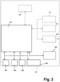
- Fig. 1 is a schematic drawing and Fig. 2 is a schematic diagram of the medical device 100 according to an embodiment of the present disclosure.
- the medical device 100 comprises a blood glucose measurement unit 110, which is arranged to measure the blood glucose level and data processing. Further, the measurement unit 110 comprises an interface and a slot 112 for inserting a test strip.
- the blood glucose measurement unit 110 may forward e.g. blood glucose measurement data to a data storage 130 (storage unit or means) or memory, such as a Flash memory. Alternatively, the blood glucose measurement unit 110 may retrieve stored data such as e.g. blood glucose value data from the data storage 130.
- the blood glucose measurement unit further comprises a processor (processing unit or means), such as a microcontroller or microprocessor, a digital signal processor, and / or the like for data processing.
- the blood glucose measurement unit 110 is further connected to a user input unit 150 of a user interface.
- the user input unit 150 is arranged to receive input from the user of the medical device 100 for example by key 151, confirmation key (OK button) 152, key 153 for scrolling down (downward button) and key 154 for scrolling up (upward button).
- the user input data are forwarded from the user input unit 150 to the blood glucose measurement unit 110, which may forward it to the processor and/or to the data storage 130.
- the user interface of medical device 100 comprises a display unit 160 with a display 162, which is connected to the blood glucose measurement unit 110 as well.
- the display unit 160 may receive data to be displayed by the display 162 from the blood glucose measurement unit 110.
- the medical device 100 may additionally comprise a further interface 170, for example a wired interface such as a serial port, a Universal Serial Bus (USB) interface, a mini-USB interface, or a wireless interface such as an infrared (e.g. an IRDA) interface, a Bluetooth TM interface, and / or the like, in order to receive data and / or to transmit data.
- the interface 170 may be connected to the blood glucose measurement unit 110 in order to receive data from the blood glucose measurement unit 110 and/or to forward data to blood glucose measurement unit 110.
- the medical device 100 comprises a clock unit 180 which provides a date and time information, for example based on a clock generator, which may be displayed at the display 162.
- the clock unit 180 may provide date and time information to the blood glucose measurement unit 110 for data processing and/or for generating a time stamp for an associated blood glucose measurement.
- the medical device 100 further comprises an NFC antenna 193, an energy supply unit 195 and a charge control unit 196 which are all electrically connected with the measurement unit 110 and with each other. Further, these components are connected with an energy storage unit 190 formed, for example, by a rechargeable battery or a capacitor (super-cap) which provides electrical energy (voltage or current) for the components of the medical device 100.
- the energy storage unit 190 is therefore connected with all components of the medical device 100 for energy supply.
- the medical device 100 comprises a blood glucose measurement unit 110.
- the blood glucose measurement unit 110 may be arranged to measure the blood glucose level in the blood of e.g. the user by testing a drop of blood on a test strip that is inserted into the slot 112. The measurement may be made using e.g. an electrochemical method or an optical method by the measurement unit 110. Full insertion of the test strip in the slot 112 may be detected by a respective sensor, e.g. a proximity switch, and may activate the measurement unit 110.
- the blood glucose measurement unit 110 is arranged to measure the blood glucose level of the user via infrared diagnosis or an alternative contactless measurement method.
- the measurement of the blood glucose measurement may be triggered by user input which is received via user input unit 150 or based on a signal from the slot 112 detecting a test strip.
- the trigger signal may be generated automatically by the clock unit 180 or by the processor of the blood glucose measurement unit 110.
- the blood glucose measurement unit 110 may comprise input ports and output ports of a microprocessor or a bus system managing the data handling between several functional units. This includes bus systems, such as e.g. Advanced Microprocessor Bus Architecture bus systems implemented in a microprocessor or external bus systems connected to a microprocessor.
- the blood glucose measurement unit 110 may retrieve data from the data storage 130 on demand and forwarded them to its processor, to the display unit 160 or to the interface 170.
- the blood glucose measurement unit 110 may forward control signals, such as trigger signals or control signals, e.g. to the display unit 160 or the interface 170.
- the data storage 130 is arranged to store data entered via the user input unit 150, a plurality of blood glucose measurement data received from the blood glucose measurement unit 110 together with a time stamp and/or at least one event tag associated to each measurement data, data calculated from the plurality of blood glucose measurement values processed by the processor 140 and/or data received via interface 170.
- data storage 130 is arranged to provide the stored data to the processor of the blood glucose measurement unit 110, to the display unit 160 and/or to the interface 170.
- the data storage 130 may be implemented as a semiconductor memory such as a Flash memory. Alternatively, it is implemented as a hard disk memory or an on-chip memory of the processor of the blood glucose measurement unit 110.
- the user input unit 150 may be implemented as a keyboard comprising one or more push buttons 151, 152, 153, 154.
- the keyboard may comprise one or more soft keys, wherein the function of the soft keys may be displayed on the display 162.
- the user input unit 150 is a key board or a touch screen.
- the user input unit 150 comprises a microphone for receiving speech input so that data can be entered via speech input.
- the display unit 160 may comprise an LCD or LED display 162.
- the display may display a number of alphanumerical characters so that e.g. the presently measured blood glucose value can be displayed together with additional instructions for the user.
- the display unit 160 comprises a graphic display in order to display graphs or graphics such as icons. Further the display of the display unit 160 may comprise a touchscreen.
- the interface 170 may be realized as a wireless interface, such as IRDA, Bluetooth TM , GSM, UMTS, ZigBee, or WI-FI, etc.
- the interface is a wired interface, such as a USB port, mini-USB port, serial data port, parallel data port, etc., for receiving and transmitting data.
- the medical device 100 does not comprise an interface 170.
- medical device 100 may comprise a memory card reader or a memory card reader interface.
- the memory card reader may be adapted to read information from a memory card, such as a Flash memory card, or any type of SIM card.
- the memory card comprises a memory, wherein at least one of a selected algorithms together with corresponding parameters, a history of the blood glucose values and / or insulin doses administered, etc. is stored.
- the relevant data may still be stored on the memory card which can be easily removed from the memory card reader of the medical device 100 and transferred to a new medical device 100.
- the memory card 100 may be used in order to provide information on the history of the treatment to e.g. an HCP.
- the memory card is a SIM card providing subscriber identification for a mobile communication network and the interface unit 170 is additionally a mobile communication interface
- additional functions of the medical device 100 may be unlocked by the provider of the SIM card via a telecommunication channel.
- This offers the possibility that the medical device 100 can communicate with other telecommunication devices via predefined channels, such as UMTS or GSM.
- IMSI international mobile subscriber identity
- the medical device 100 identifies itself within the network and, thus, can be addressed via the network.
- the medical device 100 can be easily checked, remote controlled, updated, monitored, etc., via interface unit 170, e.g. by addressing the mobile communication unit with a phone number.
- the medical device 100 may be able to transmit data via SMS, e-mail or via mobile internet connection. Moreover, this offers the possibility to locate the medical device 100 in an emergency case.
- the blood glucose measurement unit 110 is a continuous sensor which is e.g. implanted a dose delivery unit with an insulin pump forming an automatic delivery system may be additionally provided.
- the energy supply unit 190 and the charge control unit 196 it can be avoided to conduct a blood glucose measurement with too little voltage and/or charge thereby reducing the risk to measure false measurement values because the charge control unit 196 is adapted to determine the electric charge contained in the energy storage unit 190 before the blood glucose measurement is conducted by the measurement unit 110.
- the charge control unit 196 checks the charge contained in the energy storage unit 190 just after activation of the measurement unit 110 by full insertion of the strip into the slot 112. The measurement is only conducted if the electric charge contained in the energy storage unit 190 determined by the charge control unit 196 is greater than a pre-defined minimum charge value. Otherwise, a pre-defined visible, audible and/or tactile signal is produced by the display unit 160, for example a respective warning text at the display 162.
- the charge control unit 196 activates the energy supply unit 195 for energy withdrawal using the NFC antenna 193 if the electric charge contained in the energy storage unit 190 determined by the charge control unit 196 is equal to or below a pre-defined minimum charge value.
- the NFC antenna (also referred to as internal antenna) 193 may have a dimension of 3 x 3 x 0.5 cm, and may provide a maximum of 3 mA at 3 V.
- an external NFC antenna of a mobile phone or smart phone or another charging device may be used.
- the NFC antenna 193 operates at 13.56 MHz on ISO/IEC 18000-3 air interface and at rates ranging from 106 kbit/s to 424 kbit/s.
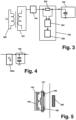
- the NFC antenna 193 receives energy from an electromagnetical field produced by the external antenna 200 (see Fig. 3 and 5 ).
- the charge control unit 196 comprises a gas gauge.
- the gas gauge (also referred to as fuel gauge or Coulomb counter) may be used in the electronic field for the load count in an energy supply unit such as a rechargeable battery, similar to the tank meter in the car. It comprises a resistor 202 having very low resistance and a voltage meter 204 determining the voltage drop over the resistor 202 in order to determine the electric charge contained in the energy storage unit 190.
- the gas gauge may further comprise an A/D converter.
- a processor 206 of the charge control unit is connected to the clock unit 180. The A/D converter converts the measured voltage drop over the resistor 202 measured by the voltage meter 204 into an A/D converter count.
- the voltage drop or its A/D convertor count is added together by the processor 206 over a pre-defined time period provided by the clock unit 180 thereby determining a voltage value which reflects the level of current and its direction flowing to the energy storage unit 190.
- High current causes an accelerated increase of the counter value and indicates a high electric charge and low current a low increase indicating a low electric charge contained in the energy storage unit 190.
- Negative current causes a decrease in the counter value and indicates the discharge mode of the energy storage unit 190. If the current is continuously observed, the charge value contained in the energy storage unit 190 can be determined.
- the charge control unit 196A continuously observes time-dependent change in the voltage drop V over the energy supply unit 190, which is, for example, a capacitor.
- the energy supply unit 190 which is, for example, a capacitor.
- each charging and decharging step causes a change in the voltage drop over the capacitor.
- FIG. 5 An embodiment of an NFC antenna 193 is shown in Fig. 5 .
- This figure depicts the PCB 197 comprising an electrical circuit on its front face. On its back face a coil 198 is attached forming the antenna.
- the NFC antenna 193 comprises a ferrit core or disc 199 on the front side of the PCB in order provide a more efficient charging.
- Ferrites are electrically bad or non-conductive ferromagnetic ceramic materials from the iron oxide hematite (Fe2O3), rarely of magnetite (Fe3O4) and other metal oxides. Depending on the composition ferrites are magnetically hard or magnetically soft.
- the medical device 100 is capable to perform a number of operating processes.
- the medical device 100 performs initialization step 310 for initializing the functional components of the medical device 100.
- the different operation modes which are implemented in the medical device 100 are displayed in the display step 320, for example operation modes such as "Measure BG", "Logbook” and/or "Settings".
- step 330 the user selects one of the displayed operation modes via the user input unit 150, for example by means of the keys 153, 154 for scrolling down or up, and confirms the selection using the confirmation key 152.
- step 340 the selected operation mode is executed.
- the mode "Measure BG" is selected for executing a blood glucose measurement.
- the user/patient is requested to provide a test strip with a blood sample.
- the “Logbook” mode the history of previous measurements and statistical results may be calculated and displayed.
- the “Settings” mode allows the user to define and change some parameters of the medical device 100.
- step 350 a drop of blood is applied to the test portion of the test strip which is inserted in slot 112 of the medical device 100.
- steps 310 to 340 may be skipped in the case that a specific operation mode is preselected.
- the preselected operation mode which is either preselected by the user or automatically selected in accordance with a specific event, for example the detection of a fully inserted test strip in slot 112
- the operating process proceeds with the following step 350 and checks the status of the energy storage unit 190 using the charge control unit 196 as indicated above. If the electric charge contained in the energy storage unit 190 determined by the charge control unit 196 is greater than the pre-defined minimum charge value, the method continues with step 360 and asks the user to apply a drop of blood to the test strip.
- the measurement unit 110 determines e. g. by an electrochemical method the blood glucose level and displays the respective new measurement value at the display 162 using the test strip inserted into the slot 112.
- the clock unit 180 In the next step 370 the clock unit 180 generates the time stamp of the present measurement comprising a date and time information.
- the time stamp is also displayed in display 162 and both, the present blood glucose measurement value and the associated time stamp is transferred by receiving unit 120 to the data storage 130.
- the processor 140 compares the time stamp of the present blood glucose measurement value with each of time ranges for tagging preselection of the events stored in the data storage 130 which events may be selected as the associated event tag. If the time stamp of the present measurement value (new measurement value), in particular the time information of the time stamp, lies within the current time range of e. g. the fasting event automatically the fasting tag is provided for confirmation by the user and displayed with a respective sign, for example a struck out, empty apple, at display 162. In order to show that a confirmation is necessary the tag sign 168 displayed on display 162 is blinking/flashing. Now, the user may confirm the fasting tag for example by pressing the confirmation key 152.
- the user may change the tag using the up and down keys 153, 154 into the pre-meal tag, the post-meal tag or the no-tag (nil). If the correct tag is chosen the user confirms the tag by pressing the confirmation key 152. By confirmation of the tag with the confirmation key 152 the flashing of the displayed tag sign is stopped and the tag sign is displayed continuously without blinking. In this state, pressing the up/down keys 153, 154 will not change the tag. Then, the processor 140 initiates storage of the associated, confirmed tag with regard to the recent measurement value in the data storage 130 via blood glucose measurement unit 110.
- step 380 the processor 140 cannot find any range for tagging pre-selection which refers to the time information of the time stamp of the present measurement value, the no-tag is preselected.
- the user is allowed to change the tag in the above explained manner but only within a predefined time range from the associated time stamp of the blood glucose measurement value, for example within 10 days.
- a comment to the present measurement value may be selected by the user using the up and down keys 153, 154.
- the comment may then be confirmed with the confirmation key 152, wherein the chosen comment is then stored in the data storage 130 associated to the present measurement value as well.
- the device may turn into the sleep state automatically after, for example, 120 seconds without any new action. Once the device has returned a new measurement value, the device turns to the sleep state automatically after for example 60 seconds without any user interaction.
- the transformation into the sleep state is depicted in Fig. 6 by the step 400.
- step 410 the display unit 160 produces a pre-defined visible, audible and/or tactile signal for the user in order to tell the user that the charge of the energy storage unit is too low and a measurement cannot be conducted at this time. For example, a respective warning message is displayed at the display 162. The method then further proceeds with step 400.
- the charge control unit 196 may activate the energy supply unit 195 for energy withdrawal using the NFC antenna 193 if the electric charge contained in the energy storage unit determined by the charge control unit is equal to or below a pre-defined minimum charge value.
- the medical device 100 provides at least one memory review mode which is called “Logbook” mode.
- the “Logbook” mode may be entered when the user activates the medical device 100 by pressing e.g. the confirmation button 152.
- the measurement values are, for example, displayed in the order in which the entries are entered into the device, or alternatively according to the time and date assigned to the measurement values. In particular the most recent blood glucose measurement value is shown upon entry into the "Logbook” mode. Pressing the up and down keys 153, 154 the user may scroll through the records, for example by pressing the down key 153 the user may scroll backwards in time and by pressing the up key 154 the user scrolls forward in time.
Landscapes
- Engineering & Computer Science (AREA)
- Health & Medical Sciences (AREA)
- Life Sciences & Earth Sciences (AREA)
- Physics & Mathematics (AREA)
- Biomedical Technology (AREA)
- Power Engineering (AREA)
- Chemical & Material Sciences (AREA)
- Molecular Biology (AREA)
- Hematology (AREA)
- Biophysics (AREA)
- General Health & Medical Sciences (AREA)
- Pathology (AREA)
- Immunology (AREA)
- Urology & Nephrology (AREA)
- Computer Networks & Wireless Communication (AREA)
- Medicinal Chemistry (AREA)
- Analytical Chemistry (AREA)
- General Physics & Mathematics (AREA)
- Biochemistry (AREA)
- Food Science & Technology (AREA)
- Animal Behavior & Ethology (AREA)
- Surgery (AREA)
- Veterinary Medicine (AREA)
- Public Health (AREA)
- Medical Informatics (AREA)
- Heart & Thoracic Surgery (AREA)
- Optics & Photonics (AREA)
- Emergency Medicine (AREA)
- Human Computer Interaction (AREA)
- Manufacturing & Machinery (AREA)
- Chemical Kinetics & Catalysis (AREA)
- Cell Biology (AREA)
- Electrochemistry (AREA)
- General Chemical & Material Sciences (AREA)
- Microbiology (AREA)
- Biotechnology (AREA)
- Diabetes (AREA)
- Measurement Of The Respiration, Hearing Ability, Form, And Blood Characteristics Of Living Organisms (AREA)
- Infusion, Injection, And Reservoir Apparatuses (AREA)
- Measuring And Recording Apparatus For Diagnosis (AREA)
Description
- The present disclosure relates to a medical device for supporting health control and an operation method for such medical device.
- The following description of the present disclosure mainly refers to diabetes as a health problem and the blood glucose level as the physiological parameter to be controlled in order to assess the effectiveness of the prescribed treatment.
- Diabetes mellitus is a group of metabolic diseases in which a person has high blood sugar, either because the pancreas does not produce enough insulin, or because cells do not respond to the insulin that is produced. The treatment of diabetes concentrates on keeping blood sugar levels as close to normal ("euglycemia") as possible, without causing hypoglycemia. This can usually be accomplished with diet, exercise, and use of appropriate medications (insulin in the case of type 1 diabetes; oral medications, as well as possibly insulin, in type 2 diabetes).
- Essential elements of the management of diabetes with insulin are periodic checks of the glucose concentration in the blood performed by the patients themselves, in order to obtain regular information on the progress and success of the prescribed treatment. This understanding, and patient participation is vital, since the complications of diabetes are far less common and less severe in patients who have well-managed blood sugar levels. With regard to this it has to be considered that the blood glucose level fluctuates throughout the day and is directly influenced by the amount of insulin administered, as well as lifestyle factors such as the amount and kind of food that is consumed, the exercise level and stress.
- Therefore, the monitoring of the sugar level in the blood serves a dual purpose: on the one hand it provides the patient with information about the current status of glycemic control. On the other hand can the measured values serve as information for the patient or a healthcare professional (HCP) to determine whether an adjustment in the medication, for example the amount of insulin to be taken, is indicated.
- In order to achieve these goals or to get as close as possible to the desired glycemic control, it is common practice that blood glucose measurement values are monitored once or several times during the day using a blood glucose meter (BGM), following a testing regime normally prescribed by an HCP. A BGM usually comprises an energy storage unit which provides supply voltage to a display and/or another communication unit, a memory and a measurement unit and/or other elements of the BGM. The energy storage unit may be charged using NFC (near field control). NFC is rooted in radio-frequency identification technology (known as RFID) which allows compatible hardware to both supply power to and communicate with an otherwise unpowered and passive electronic tag using radio waves. This is used for energy supply, identification, authentication and tracking.
-
US 2017/055890 A1 discloses a sensor module for determining a concentration an analyte in a body fluid of a user. The sensor module includes a sensor element adapted to determine the concentration of the analyte and a control device connected to the sensor element, wherein the control device includes at least one data collection device adapted to collect measurement data acquired by using the sensor element. The control device further includes a wireless near-field communication device adapted to transmit measurement data and a rechargeable energy storage device. Energy may be transferred from an energy storage device of a separate recharging module into the energy storage device of the sensor module. The control device is adapted to transmit a demand for recharging the rechargeable energy storage device via the near-field communication device. - In
US 9,197,082 B1 -
US 2015/038332 A1 discloses a chronic disease management system that includes a data management unit and a biosensor in the form of a physiological measurement test strip. The meter measures the battery voltage to determine whether there is enough power left to complete the test and safely store the result in memory. More specifically, a depletion threshold, at which voltage or amperage the device can no longer provide reliable measurement testing, is about 72% of a rated voltage or about 2.4 volts. -
US 2017/0347927 A1 describes a glucose monitoring system including a sensor, a transmitter unit, and a receiver unit. A magnetic field generator unit of the receiver unit is configured for providing power recharge. In particular, the magnetic field generator may be configured to inductively charge a rechargeable power source of the transmitter unit. A magnetic field radiation section includes a flexible ferrite layer having disposed thereon an adhesive layer, on which a multilayered PCB core coil inductor is provided. - The article Eric Freudenthal et al.: "Suitability of NFC for Medical Device Communication and Power Delivery" (Engineering in Medicine and Biology Workshop, 2007 IEEE Dallas, ISBN 978-1-4244-1626-4) relates to the possibility of implementing NFC in medical devices.
-
US 2017/0331309 A1 shows a circuit including a battery charger with a fuel gauge that can be applied to a blood glucose meter. The battery charger can be coupled with a primary power source. The primary power source may be a power outlet, a generator, an AC/DC wall-mount adapter, a USB port, or other power source capable of providing sufficient power to charge a battery. Upon disconnection from the primary power source, a direction of current, previously flowing from the battery to a sensing resistor, changes or reverses. A reversed polarity in the sensing resistor triggers the fuel gauge to start tracking the current out of the battery by counting the energy units that leave the battery as the battery is discharging. -
US 2005/0038322 A1 discloses a monitoring system including a sensor set. A sensor produces a signal that corresponds to a blood glucose level. The sensor set communicates these signals to a characteristic monitor that is designed to interpret these signals to produce a characteristic reading or value for the user. The monitoring system can be coupled to an infusion pump that can providing a medication to a user. Alarm conditions of the pump include a sensor low battery alarm and a dead battery alarm. - The document
WO 2013/063634 A1 relates to a measurement device for measuring glucose, comprising: a glucose sensor for determining the glucose content in a solution or fluid, in particular in blood, and for reproducing the measured glucose content in the form of an electrical signal with measurement data presented in encoded form; an NFC antenna; an energy withdrawal unit downstream of the NFC antenna, which controls the NFC antenna in such a way that the NFC antenna withdraws energy from the field surrounding the NFC antenna if electromagnetic waves in a predetermined frequency range are present, and wherein the NFC antenna is upstream of the glucose sensor and supplies it with electrical energy. - In order to realize sufficient health control such BGM needs to be ready for operation at the time the measurements of the physiological parameter are needed or scheduled. For adequate measurement using BGM by NFC a sufficient amount of energy in the form of voltage and/or charge to power is required during the measurement, for example a charge of 30 mAs for one glucose measurement. If the current measurement is influenced by too little charge and/or voltage an NFC demolition is to be expected which may potentially cause false blood glucose measurement values.
- Accordingly, it is an object of the present disclosure to guarantee that the blood glucose measurement or the measurement of other physiological parameter is not influenced by low voltage and/or charge.
- This object is solved by a medical device with the features according to claim 1.
- In particular, according to the present disclosure the medical device comprises
- a measurement unit adapted to measure a value of a physiological parameter, for example a blood glucose level,
- an energy storage unit connected with the measurement unit providing energy supply for the measurement unit,
- an internal NFC antenna,
- an energy supply unit connected with the NFC antenna and with the energy storage unit, wherein the energy supply unit controls the NFC antenna such that in the presence of an electromagnetic field of a pre-defined frequency range energy is withdrawn from the electromagnetic field surrounding the NFC antenna and stored in the energy storage unit,
- a charge control unit, connected to the energy storage unit and adapted to determine the electric charge contained in the energy storage unit, and
- a communication unit connected with the charge control unit, wherein the communication unit is adapted to output a pre-defined visible, audible and/or tactile signal if the electric charge contained in the energy storage unit determined by the charge control unit is equal or below a pre-defined minimum charge value.
- Using the above medical device comprising the NFC antenna, the energy supply unit and the charge control unit it can be avoided to conduct a measurement of a physiological parameter, a blood glucose measurement, in case too little voltage and/or charge is contained in the energy storage unit as the communication unit communicates that the device is not operational. Determination of false meas-urement values is thereby avoided. The measurement unit is adapted such that a determination of a value of the physiological parameter by the measurement unit is blocked if the if the electric charge contained in the energy storage unit determined by the charge control unit is equal to or below the pre-defined minimum charge value.
- According to one embodiment the energy storage unit may be a rechargeable battery or a capacitor with a very large capacity (X5R or Super-Cap).
- In one embodiment the NFC antenna (also referred to as internal antenna) may have a dimension of 3 x 3 x 0.5 cm, and may provide a maximum of 3 mA at 3 V.
- For energy supply an external NFC antenna of a mobile phone or smart phone or another charging device may be used.
- According to the present disclosure NFC is a set of short-range wireless technologies, typically requiring a separation of 10 cm or less. NFC operates at 13.56 MHz on ISO/IEC 18000-3 air
interface and at rates ranging from 106 kbit/s to 424 kbit/s. NFC always involves an initiator and a target; the initiator actively generates an RF field that can power a passive target. This enables NFC targets to take very simple form factors such as unpowered tags, stickers, key fobs, or cards. NFC peer-to-peer communication is possible, provided both devices are powered. NFC standards are based on existing RFID standards including ISO/IEC 14443, 18092 and those defined by the NFC Forum. NFC is standardized for example in ECMA-340 and ISO/IEC 18092. - In an embodiment the charge control unit comprises a gas gauge. The gas gauge (also referred to as fuel gauge or Coulomb counter) may be used in the electronic field for the load count in an energy supply unit such as a rechargeable battery, similar to the tank meter in the car. It comprises a resistor having very low resistance and determines the integral over the electric current flowing through the resistor (or voltage drop over the resistor as equivalent) in order to determine the electric charge contained in the energy supply unit. The gas gauge further may comprise an A/D converter, a counter and may be connected to a clock unit. The A/D converter converts the measured voltage drop over the resistor into an A/D converter count which reflects the level of current and its direction within a pre-defined time period provided by the clock unit. High current causes an accelerated increase of the counter value and indicates a high electric charge and low current a low increase indicating a low electric charge contained in the energy supply unit. Negative current causes a decrease in the counter value and indicates the discharge mode of the energy supply unit.
- In another embodiment the charge control unit continuously observes time-dependent change in the voltage drop over the energy supply unit, which is, for example, a capacitor. In this case each charging and decharging step causes a change in the voltage drop over the capacitor. The charge control unit observes the development of the voltage drop over time thereby determining the amount of charge flowing to or from the capacitor based on the continuous observation of the voltage drop and the well-known relation Q = C x U, wherein U is the voltage, C is the capacity of the capacitor and Q is the charge.
- The NFC antenna comprises a ferrit core or disc in order provide a more efficient charging. Ferrites are electrically bad or non-conductive ferromagnetic ceramic materials from the iron oxide hematite (Fe2O3), rarely of magnetite (Fe3O4) and other metal oxides. Depending on the composition ferrites are magnetically hard or magnetically soft.
- In an embodiment the NFC antenna and/or the ferrit core or disc is formed by a structure printed on a PCB (Printed circuit board).
- In further embodiments at least one of the following features may be included:
- a solar cell connected with the energy storage unit for an additional energy supply, the solar cell may be integrated in the PCB,
- the measurement unit may provide an integrated A1c estimation algorithm,
- the device may be sealed such that it can be cleaned with a detergent capable MRSA,
- the device may comprise an integrated temperature tracker which checks the temperature continuously, wherein a temperature below and equal to a minimum temperature value or a temperature above and equal to a maximum temperature value (the maximum temperature value is greater than the minimum temperature value) prevents the user to conduct a measurement of the physiological parameter in order to avoid false measurement values,
- the device may comprise an interface to an NFC insulin managing device in order to act independently from a mobile device,
- the device may provide a management of BGM data,
- the device may display measured or stored BGM data as well as BGM target data,
- the interface of the device may provide a connection to an app, cloud, HCP data base as well as access to this data base.
- The device may be further adapted to administrate a medicament (i.e. additionally works as a drug delivery device) based on the measured value or values of the physiological parameter, e.g. the measured blood glucose values, for example the recently measured value or the values measured over a pre-defined time period. However, no drug delivery method is claimed.
- The terms "drug" or "medicament" are used synonymously herein and describe a pharmaceutical formulation containing one or more active pharmaceutical ingredients or pharmaceutically acceptable salts or solvates thereof, and optionally a pharmaceutically acceptable carrier. An active pharmaceutical ingredient ("API"), in the broadest terms, is a chemical structure that has a biological effect on humans or animals. In pharmacology, a drug or medicament is used in the treatment, cure, prevention, or diagnosis of disease or used to otherwise enhance physical or mental well-being. A drug or medicament may be used for a limited duration, or on a regular basis for chronic disorders.
- As described below, a drug or medicament can include at least one API, or combinations thereof, in various types of formulations, for the treatment of one or more diseases. Examples of API may include small molecules having a molecular weight of 500 Da or less; polypeptides, peptides and proteins (e.g., hormones, growth factors, antibodies, antibody fragments, and enzymes); carbohydrates and polysaccharides; and nucleic acids, double or single stranded DNA (including naked and cDNA), RNA, antisense nucleic acids such as antisense DNA and RNA, small interfering RNA (siRNA), ribozymes, genes, and oligonucleotides. Nucleic acids may be incorporated into molecular delivery systems such as vectors, plasmids, or liposomes. Mixtures of one or more drugs are also contemplated.
- The drug or medicament may be contained in a primary package or "drug container" adapted for use with a drug delivery device. The drug container may be, e.g., a cartridge, syringe, reservoir, or other solid or flexible vessel configured to provide a suitable chamber for storage (e.g., short- or long-term storage) of one or more drugs. For example, in some instances, the chamber may be designed to store a drug for at least one day (e.g., 1 to at least 30 days). In some instances, the chamber may be designed to store a drug for about 1 month to about 2 years. Storage may occur at room temperature (e.g., about 20°C), or refrigerated temperatures (e.g., from about - 4°C to about 4°C). In some instances, the drug container may be or may include a dual-chamber cartridge configured to store two or more components of the pharmaceutical formulation to-be-administered (e.g., an API and a diluent, or two different drugs) separately, one in each chamber. In such instances, the two chambers of the dual-chamber cartridge may be configured to allow mixing between the two or more components prior to and/or during dispensing into the human or animal body. For example, the two chambers may be configured such that they are in fluid communication with each other (e.g., by way of a conduit between the two chambers) and allow mixing of the two components when desired by a user prior to dispensing. Alternatively or in addition, the two chambers may be configured to allow mixing as the components are being dispensed into the human or animal body.
- The drugs or medicaments contained in the drug delivery devices as described herein can be used for the treatment and/or prophylaxis of many different types of medical disorders. Examples of disorders include, e.g., diabetes mellitus or complications associated with diabetes mellitus such as diabetic retinopathy, thromboembolism disorders such as deep vein or pulmonary thromboembolism. Further examples of disorders are acute coronary syndrome (ACS), angina, myocardial infarction, cancer, macular degeneration, inflammation, hay fever, atherosclerosis and/or rheumatoid arthritis. Examples of APIs and drugs are those as described in handbooks such as Rote Liste 2014, for example, without limitation, main groups 12 (antidiabetic drugs) or 86 (oncology drugs), and Merck Index, 15th edition.
- Examples of APIs for the treatment and/or prophylaxis of type 1 or type 2 diabetes mellitus or complications associated with type 1 or type 2 diabetes mellitus include an insulin, e.g., human insulin, or a human insulin analogue or derivative, a glucagon-like peptide (GLP-1), GLP-1 analogues or GLP-1 receptor agonists, or an analogue or derivative thereof, a dipeptidyl peptidase-4 (DPP4) inhibitor, or a pharmaceutically acceptable salt or solvate thereof, or any mixture thereof. As used herein, the terms "analogue" and "derivative" refers to a polypeptide which has a molecular structure which formally can be derived from the structure of a naturally occurring peptide, for example that of human insulin, by deleting and/or exchanging at least one amino acid residue occurring in the naturally occurring peptide and/or by adding at least one amino acid residue. The added and/or exchanged amino acid residue can either be codable amino acid residues or other naturally occurring residues or purely synthetic amino acid residues. Insulin analogues are also referred to as "insulin receptor ligands". In particular, the term "derivative" refers to a polypeptide which has a molecular structure which formally can be derived from the structure of a naturally occurring peptide, for example that of human insulin, in which one or more organic substituent (e.g. a fatty acid) is bound to one or more of the amino acids. Optionally, one or more amino acids occurring in the naturally occurring peptide may have been deleted and/or replaced by other amino acids, including non-codeable amino acids, or amino acids, including non-codeable, have been added to the naturally occurring peptide. Examples of insulin analogues are Gly(A21), Arg(B31), Arg(B32) human insulin (insulin glargine); Lys(B3), Glu(B29) human insulin (insulin glulisine); Lys(B28), Pro(B29) human insulin (insulin lispro); Asp(B28) human insulin (insulin aspart); human insulin, wherein proline in position B28 is replaced by Asp, Lys, Leu, Val or Ala and wherein in position B29 Lys may be replaced by Pro; Ala(B26) human insulin; Des(B28-B30) human insulin; Des(B27) human insulin and Des(B30) human insulin.
- Examples of insulin derivatives are, for example, B29-N-myristoyl-des(B30) human insulin, Lys(B29) (N- tetradecanoyl)-des(B30) human insulin (insulin detemir, Levemir®); B29-N-palmitoyl-des(B30) human insulin; B29-N-myristoyl human insulin; B29-N-palmitoyl human insulin; B28-N-myristoyl LysB28ProB29 human insulin; B28-N-palmitoyl-LysB28ProB29 human insulin; B30-N-myristoyl-ThrB29LysB30 human insulin; B30-N-palmitoyl- ThrB29LysB30 human insulin; B29-N-(N-palmitoyl-gamma-glutamyl)-des(B30) human insulin, B29-N-omega-carboxypentadecanoyl-gamma-L-glutamyl-des(B30) human insulin (insulin degludec, Tresiba®); B29-N-(N-lithocholyl-gamma-glutamyl)-des(B30) human insulin; B29-N-(ω-carboxyheptadecanoyl)-des(B30) human insulin and B29-N-(ω-carboxyheptadecanoyl) human insulin.
- Examples of GLP-1, GLP-1 analogues and GLP-1 receptor agonists are, for example, Lixisenatide (Lyxumia®), Exenatide (Exendin-4, Byetta®, Bydureon®, a 39 amino acid peptide which is produced by the salivary glands of the Gila monster), Liraglutide (Victoza®), Semaglutide, Taspoglutide, Albiglutide (Syncria®), Dulaglutide (Trulicity®), rExendin-4, CJC-1134-PC, PB-1023, TTP-054, Langlenatide / HM-11260C, CM-3, GLP-1 Eligen, ORMD-0901, NN-9924, NN-9926, NN-9927, Nodexen, Viador-GLP-1, CVX-096, ZYOG-1, ZYD-1, GSK-2374697, DA-3091, MAR-701, MAR709, ZP-2929, ZP-3022, TT-401, BHM-034. MOD-6030, CAM-2036, DA-15864, ARI-2651, ARI-2255, Exenatide-XTEN and Glucagon-Xten.
- An examples of an oligonucleotide is, for example: mipomersen sodium (Kynamro®), a cholesterol-reducing antisense therapeutic for the treatment of familial hypercholesterolemia. Examples of DPP4 inhibitors are Vildagliptin, Sitagliptin, Denagliptin, Saxagliptin, Berberine. Examples of hormones include hypophysis hormones or hypothalamus hormones or regulatory active peptides and their antagonists, such as Gonadotropine (Follitropin, Lutropin, Choriongonadotropin, Menotropin), Somatropine (Somatropin), Desmopressin, Terlipressin, Gonadorelin, Triptorelin, Leuprorelin, Buserelin, Nafarelin, and Goserelin.
- Examples of polysaccharides include a glucosaminoglycane, a hyaluronic acid, a heparin, a low molecular weight heparin or an ultra-low molecular weight heparin or a derivative thereof, or a sulphated polysaccharide, e.g. a poly-sulphated form of the above-mentioned polysaccharides, and/or a pharmaceutically acceptable salt thereof. An example of a pharmaceutically acceptable salt of a poly-sulphated low molecular weight heparin is enoxaparin sodium. An example of a hyaluronic acid derivative is Hylan G-F 20 (Synvisc®), a sodium hyaluronate.
- The term "antibody", as used herein, refers to an immunoglobulin molecule or an antigen-binding portion thereof. Examples of antigen-binding portions of immunoglobulin molecules include F(ab) and F(ab')2 fragments, which retain the ability to bind antigen. The antibody can be polyclonal, monoclonal, recombinant, chimeric, de-immunized or humanized, fully human, non-human, (e.g., murine), or single chain antibody. In some embodiments, the antibody has effector function and can fix complement. In some embodiments, the antibody has reduced or no ability to bind an Fc receptor. For example, the antibody can be an isotype or subtype, an antibody fragment or mutant, which does not support binding to an Fc receptor, e.g., it has a mutagenized or deleted Fc receptor binding region. The term antibody also includes an antigen-binding molecule based on tetravalent bispecific tandem immunoglobulins (TBTI) and/or a dual variable region antibody-like binding protein having cross-over binding region orientation (CODV).
- The terms "fragment" or "antibody fragment" refer to a polypeptide derived from an antibody polypeptide molecule (e.g., an antibody heavy and/or light chain polypeptide) that does not comprise a full-length antibody polypeptide, but that still comprises at least a portion of a full-length antibody polypeptide that is capable of binding to an antigen. Antibody fragments can comprise a cleaved portion of a full length antibody polypeptide, although the term is not limited to such cleaved fragments. Antibody fragments that are useful in the present disclosure include, for example, Fab fragments, F(ab')2 fragments, scFv (single-chain Fv) fragments, linear antibodies, monospecific or multispecific antibody fragments such as bispecific, trispecific, tetraspecific and multispecific antibodies (e.g., diabodies, triabodies, tetrabodies), monovalent or multivalent antibody fragments such as bivalent, trivalent, tetravalent and multivalent antibodies, minibodies, chelating recombinant antibodies, tribodies or bibodies, intrabodies, nanobodies, small modular immunopharmaceuticals (SMIP), binding-domain immunoglobulin fusion proteins, camelized antibodies, and VHH containing antibodies. Additional examples of antigen-binding antibody fragments are known in the art.
- The terms "Complementarity-determining region" or "CDR" refer to short polypeptide sequences within the variable region of both heavy and light chain polypeptides that are primarily responsible for mediating specific antigen recognition. The term "framework region" refers to amino acid sequences within the variable region of both heavy and light chain polypeptides that are not CDR sequences, and are primarily responsible for maintaining correct positioning of the CDR sequences to permit antigen binding. Although the framework regions themselves typically do not directly participate in antigen binding, as is known in the art, certain residues within the framework regions of certain antibodies can directly participate in antigen binding or can affect the ability of one or more amino acids in CDRs to interact with antigen.
- Examples of antibodies are anti PCSK-9 mAb (e.g., Alirocumab), anti IL-6 mAb (e.g., Sarilumab), and anti IL-4 mAb (e.g., Dupilumab).
- Pharmaceutically acceptable salts of any API described herein are also contemplated for use in a drug or medicament in a drug delivery device. Pharmaceutically acceptable salts are for example acid addition salts and basic salts.
- Those of skill in the art will understand that modifications (additions and/or removals) of various components of the APIs, formulations, apparatuses, methods, systems and embodiments described herein may be. The invention is defined by the appended claims.
- The disclosure further refers to a method for operation a medical device according to the above explained embodiments, which comprises the following steps:
- determining the electric charge contained in the energy storage unit before one measurement of the physiological parameter is conducted by the measurement unit,
- measuring the physiological parameter using the measurement unit only if the electric charge contained in the energy storage unit determined by the charge control unit greater than a pre-defined minimum charge value, and
- output a pre-defined visible, audible and/or tactile signal by the communication unit if the electric charge contained in the energy storage unit determined by the charge control unit is equal to or below the pre-defined minimum charge value.
- In one embodiment the method further comprises the step of activating the energy supply unit for energy withdrawal using the NFC antenna if the electric charge contained in the energy storage unit determined by the charge control unit is equal to or below the pre-defined minimum charge value.
- The above method reduces the risk of determination of false measurement values as well. Exemplary embodiments of the present disclosure are described herein with reference to schematic drawings, in which
- Fig. 1
- shows the medical device according to an embodiment of the present disclosure in a perspective view;
- Fig. 2
- shows a diagram of the medical device as shown in
Fig. 1 ; - Fig. 3
- depicts the circuitry of a first embodiment of a charge control unit for the medical device of
Fig. 1 ; - Fig. 4
- shows a second embodiment of a charge control unit for the medical device of
Fig. 1 ; - Fig. 5
- shows an embodiment of a NFC antenna on a PCB; and
- Fig. 6
- depicts a flow diagram containing a procedure realized by the medical device of
Fig. 1 in the "Measure BG" mode. - The following paragraphs will describe various embodiments of the present disclosure. For exemplary purpose only, the embodiments are outlined in relation to a medical device supporting health control measuring a blood glucose value and its operation method. However, the used terminology and the description of the embodiments with respect to the medical device or health indicating method are not intended to limit the principles and ideas of the present disclosure to such a single device or method
-
Fig. 1 is a schematic drawing andFig. 2 is a schematic diagram of themedical device 100 according to an embodiment of the present disclosure. Themedical device 100 comprises a bloodglucose measurement unit 110, which is arranged to measure the blood glucose level and data processing. Further, themeasurement unit 110 comprises an interface and aslot 112 for inserting a test strip. - The blood
glucose measurement unit 110 may forward e.g. blood glucose measurement data to a data storage 130 (storage unit or means) or memory, such as a Flash memory. Alternatively, the bloodglucose measurement unit 110 may retrieve stored data such as e.g. blood glucose value data from thedata storage 130. The blood glucose measurement unit further comprises a processor (processing unit or means), such as a microcontroller or microprocessor, a digital signal processor, and / or the like for data processing. - The blood
glucose measurement unit 110 is further connected to auser input unit 150 of a user interface. Theuser input unit 150 is arranged to receive input from the user of themedical device 100 for example bykey 151, confirmation key (OK button) 152, key 153 for scrolling down (downward button) andkey 154 for scrolling up (upward button). The user input data are forwarded from theuser input unit 150 to the bloodglucose measurement unit 110, which may forward it to the processor and/or to thedata storage 130. - Furthermore, the user interface of
medical device 100 comprises adisplay unit 160 with adisplay 162, which is connected to the bloodglucose measurement unit 110 as well. Thedisplay unit 160 may receive data to be displayed by thedisplay 162 from the bloodglucose measurement unit 110. - The
medical device 100 may additionally comprise afurther interface 170, for example a wired interface such as a serial port, a Universal Serial Bus (USB) interface, a mini-USB interface, or a wireless interface such as an infrared (e.g. an IRDA) interface, a Bluetooth™ interface, and / or the like, in order to receive data and / or to transmit data. Theinterface 170 may be connected to the bloodglucose measurement unit 110 in order to receive data from the bloodglucose measurement unit 110 and/or to forward data to bloodglucose measurement unit 110. - Additionally, the
medical device 100 comprises aclock unit 180 which provides a date and time information, for example based on a clock generator, which may be displayed at thedisplay 162. For example, theclock unit 180 may provide date and time information to the bloodglucose measurement unit 110 for data processing and/or for generating a time stamp for an associated blood glucose measurement. - In the embodiment depicted in
Fig. 1 and2 themedical device 100 further comprises anNFC antenna 193, anenergy supply unit 195 and acharge control unit 196 which are all electrically connected with themeasurement unit 110 and with each other. Further, these components are connected with anenergy storage unit 190 formed, for example, by a rechargeable battery or a capacitor (super-cap) which provides electrical energy (voltage or current) for the components of themedical device 100. Theenergy storage unit 190 is therefore connected with all components of themedical device 100 for energy supply. - As outlined above, the
medical device 100 comprises a bloodglucose measurement unit 110. The bloodglucose measurement unit 110 may be arranged to measure the blood glucose level in the blood of e.g. the user by testing a drop of blood on a test strip that is inserted into theslot 112. The measurement may be made using e.g. an electrochemical method or an optical method by themeasurement unit 110. Full insertion of the test strip in theslot 112 may be detected by a respective sensor, e.g. a proximity switch, and may activate themeasurement unit 110. Alternatively, the bloodglucose measurement unit 110 is arranged to measure the blood glucose level of the user via infrared diagnosis or an alternative contactless measurement method. - The measurement of the blood glucose measurement may be triggered by user input which is received via
user input unit 150 or based on a signal from theslot 112 detecting a test strip. Alternatively, the trigger signal may be generated automatically by theclock unit 180 or by the processor of the bloodglucose measurement unit 110. - The blood
glucose measurement unit 110 may comprise input ports and output ports of a microprocessor or a bus system managing the data handling between several functional units. This includes bus systems, such as e.g. Advanced Microprocessor Bus Architecture bus systems implemented in a microprocessor or external bus systems connected to a microprocessor. The bloodglucose measurement unit 110 may retrieve data from thedata storage 130 on demand and forwarded them to its processor, to thedisplay unit 160 or to theinterface 170. Moreover, the bloodglucose measurement unit 110 may forward control signals, such as trigger signals or control signals, e.g. to thedisplay unit 160 or theinterface 170. - The
data storage 130 is arranged to store data entered via theuser input unit 150, a plurality of blood glucose measurement data received from the bloodglucose measurement unit 110 together with a time stamp and/or at least one event tag associated to each measurement data, data calculated from the plurality of blood glucose measurement values processed by the processor 140 and/or data received viainterface 170. - Furthermore,
data storage 130 is arranged to provide the stored data to the processor of the bloodglucose measurement unit 110, to thedisplay unit 160 and/or to theinterface 170. Thedata storage 130 may be implemented as a semiconductor memory such as a Flash memory. Alternatively, it is implemented as a hard disk memory or an on-chip memory of the processor of the bloodglucose measurement unit 110. - The
user input unit 150 may be implemented as a keyboard comprising one ormore push buttons display 162. Alternatively, theuser input unit 150 is a key board or a touch screen. Alternatively, theuser input unit 150 comprises a microphone for receiving speech input so that data can be entered via speech input. - The
display unit 160 may comprise an LCD orLED display 162. In one embodiment the display may display a number of alphanumerical characters so that e.g. the presently measured blood glucose value can be displayed together with additional instructions for the user. Alternatively or additionally, thedisplay unit 160 comprises a graphic display in order to display graphs or graphics such as icons. Further the display of thedisplay unit 160 may comprise a touchscreen. - The
interface 170 may be realized as a wireless interface, such as IRDA, Bluetooth™, GSM, UMTS, ZigBee, or WI-FI, etc. Alternatively, the interface is a wired interface, such as a USB port, mini-USB port, serial data port, parallel data port, etc., for receiving and transmitting data. In a further alternative embodiment themedical device 100 does not comprise aninterface 170. - According to another alternative embodiment,
medical device 100 may comprise a memory card reader or a memory card reader interface. The memory card reader may be adapted to read information from a memory card, such as a Flash memory card, or any type of SIM card. For this purpose, the memory card comprises a memory, wherein at least one of a selected algorithms together with corresponding parameters, a history of the blood glucose values and / or insulin doses administered, etc. is stored. Thus, in the case that themedical device 100 has a defect, the relevant data may still be stored on the memory card which can be easily removed from the memory card reader of themedical device 100 and transferred to a newmedical device 100. Moreover, thememory card 100 may be used in order to provide information on the history of the treatment to e.g. an HCP. - In the case that the memory card is a SIM card providing subscriber identification for a mobile communication network and the
interface unit 170 is additionally a mobile communication interface, additional functions of themedical device 100 may be unlocked by the provider of the SIM card via a telecommunication channel. This offers the possibility that themedical device 100 can communicate with other telecommunication devices via predefined channels, such as UMTS or GSM. Via the international mobile subscriber identity, also called IMSI, stored in the SIM card, themedical device 100 identifies itself within the network and, thus, can be addressed via the network. In such a case themedical device 100 can be easily checked, remote controlled, updated, monitored, etc., viainterface unit 170, e.g. by addressing the mobile communication unit with a phone number. - Furthermore, the
medical device 100 may be able to transmit data via SMS, e-mail or via mobile internet connection. Moreover, this offers the possibility to locate themedical device 100 in an emergency case. - In the case that the blood
glucose measurement unit 110 is a continuous sensor which is e.g. implanted a dose delivery unit with an insulin pump forming an automatic delivery system may be additionally provided. - Using the above medical device comprising the
NFC antenna 193, theenergy supply unit 190 and thecharge control unit 196 it can be avoided to conduct a blood glucose measurement with too little voltage and/or charge thereby reducing the risk to measure false measurement values because thecharge control unit 196 is adapted to determine the electric charge contained in theenergy storage unit 190 before the blood glucose measurement is conducted by themeasurement unit 110. In one embodiment, for example, thecharge control unit 196 checks the charge contained in theenergy storage unit 190 just after activation of themeasurement unit 110 by full insertion of the strip into theslot 112. The measurement is only conducted if the electric charge contained in theenergy storage unit 190 determined by thecharge control unit 196 is greater than a pre-defined minimum charge value. Otherwise, a pre-defined visible, audible and/or tactile signal is produced by thedisplay unit 160, for example a respective warning text at thedisplay 162. - In another embodiment the
charge control unit 196 activates theenergy supply unit 195 for energy withdrawal using theNFC antenna 193 if the electric charge contained in theenergy storage unit 190 determined by thecharge control unit 196 is equal to or below a pre-defined minimum charge value. - In one embodiment the NFC antenna (also referred to as internal antenna) 193 may have a dimension of 3 x 3 x 0.5 cm, and may provide a maximum of 3 mA at 3 V.
- For energy supply an external NFC antenna of a mobile phone or smart phone or another charging device may be used.
- The
NFC antenna 193 operates at 13.56 MHz on ISO/IEC 18000-3 air interface and at rates ranging from 106 kbit/s to 424 kbit/s. TheNFC antenna 193 receives energy from an electromagnetical field produced by the external antenna 200 (seeFig. 3 and 5 ). - In an embodiment shown in
Fig. 3 thecharge control unit 196 comprises a gas gauge. The gas gauge (also referred to as fuel gauge or Coulomb counter) may be used in the electronic field for the load count in an energy supply unit such as a rechargeable battery, similar to the tank meter in the car. It comprises aresistor 202 having very low resistance and avoltage meter 204 determining the voltage drop over theresistor 202 in order to determine the electric charge contained in theenergy storage unit 190. The gas gauge may further comprise an A/D converter. Aprocessor 206 of the charge control unit is connected to theclock unit 180. The A/D converter converts the measured voltage drop over theresistor 202 measured by thevoltage meter 204 into an A/D converter count. The voltage drop or its A/D convertor count is added together by theprocessor 206 over a pre-defined time period provided by theclock unit 180 thereby determining a voltage value which reflects the level of current and its direction flowing to theenergy storage unit 190. High current causes an accelerated increase of the counter value and indicates a high electric charge and low current a low increase indicating a low electric charge contained in theenergy storage unit 190. Negative current causes a decrease in the counter value and indicates the discharge mode of theenergy storage unit 190. If the current is continuously observed, the charge value contained in theenergy storage unit 190 can be determined. - In another embodiment shown in
Fig. 4 thecharge control unit 196A continuously observes time-dependent change in the voltage drop V over theenergy supply unit 190, which is, for example, a capacitor. In this case each charging and decharging step causes a change in the voltage drop over the capacitor. The charge control unit observes the development of the voltage drop over time thereby determining the amount of charge flowing to or from the capacitor based on the continuous observation of the voltage drop and the well-known relation Q = C x U, wherein U is the voltage, C is the capacity of the capacitor and Q is the charge. - An embodiment of an
NFC antenna 193 is shown inFig. 5 . This figure depicts thePCB 197 comprising an electrical circuit on its front face. On its back face acoil 198 is attached forming the antenna. Further, theNFC antenna 193 comprises a ferrit core ordisc 199 on the front side of the PCB in order provide a more efficient charging. Ferrites are electrically bad or non-conductive ferromagnetic ceramic materials from the iron oxide hematite (Fe2O3), rarely of magnetite (Fe3O4) and other metal oxides. Depending on the composition ferrites are magnetically hard or magnetically soft. - As shown in
Fig. 6 , themedical device 100 is capable to perform a number of operating processes. According to an alternative after switching on, e.g. by pressing a key 151, 152, 153 or 154, for example theconfirmation key 152 for a predetermined time, or detection of a test strip within theslot 112, themedical device 100 performsinitialization step 310 for initializing the functional components of themedical device 100. After this, the different operation modes which are implemented in themedical device 100, are displayed in thedisplay step 320, for example operation modes such as "Measure BG", "Logbook" and/or "Settings". - In
step 330 the user selects one of the displayed operation modes via theuser input unit 150, for example by means of thekeys confirmation key 152. - In
step 340 the selected operation mode is executed. As an example the mode "Measure BG" is selected for executing a blood glucose measurement. Upon execution of this mode the user/patient is requested to provide a test strip with a blood sample. - In the "Logbook" mode the history of previous measurements and statistical results may be calculated and displayed. The "Settings" mode allows the user to define and change some parameters of the
medical device 100. - After selecting the mode "Measure BG", in step 350 a drop of blood is applied to the test portion of the test strip which is inserted in
slot 112 of themedical device 100. - According to an alternative version of the operation process steps 310 to 340 may be skipped in the case that a specific operation mode is preselected. In this case, after initialization, the preselected operation mode, which is either preselected by the user or automatically selected in accordance with a specific event, for example the detection of a fully inserted test strip in
slot 112, the operating process proceeds with the followingstep 350 and checks the status of theenergy storage unit 190 using thecharge control unit 196 as indicated above. If the electric charge contained in theenergy storage unit 190 determined by thecharge control unit 196 is greater than the pre-defined minimum charge value, the method continues withstep 360 and asks the user to apply a drop of blood to the test strip. It then executes the preselected one or more operation modes, for example the mode "Measure BG". Now instep 360 themeasurement unit 110 determines e. g. by an electrochemical method the blood glucose level and displays the respective new measurement value at thedisplay 162 using the test strip inserted into theslot 112. - In the
next step 370 theclock unit 180 generates the time stamp of the present measurement comprising a date and time information. The time stamp is also displayed indisplay 162 and both, the present blood glucose measurement value and the associated time stamp is transferred by receiving unit 120 to thedata storage 130. - In the
next step 380 the processor 140 compares the time stamp of the present blood glucose measurement value with each of time ranges for tagging preselection of the events stored in thedata storage 130 which events may be selected as the associated event tag. If the time stamp of the present measurement value (new measurement value), in particular the time information of the time stamp, lies within the current time range of e. g. the fasting event automatically the fasting tag is provided for confirmation by the user and displayed with a respective sign, for example a struck out, empty apple, atdisplay 162. In order to show that a confirmation is necessary the tag sign 168 displayed ondisplay 162 is blinking/flashing. Now, the user may confirm the fasting tag for example by pressing theconfirmation key 152. - Alternatively, the user may change the tag using the up and down
keys confirmation key 152. By confirmation of the tag with theconfirmation key 152 the flashing of the displayed tag sign is stopped and the tag sign is displayed continuously without blinking. In this state, pressing the up/downkeys data storage 130 via bloodglucose measurement unit 110. - If in
step 380 the processor 140 cannot find any range for tagging pre-selection which refers to the time information of the time stamp of the present measurement value, the no-tag is preselected. - After pressing the
confirmation key 152, if the user presses the confirmation key again, the tag will start flashing again and pressing the up/down key will again allow the user to change the tag as explained above. - Further, in the "Logbook" mode the user is allowed to change the tag in the above explained manner but only within a predefined time range from the associated time stamp of the blood glucose measurement value, for example within 10 days.
- In the next optional step 390 a comment to the present measurement value may be selected by the user using the up and down
keys confirmation key 152, wherein the chosen comment is then stored in thedata storage 130 associated to the present measurement value as well. - When the
medical device 100 is in the "Measure BG" mode, the device may turn into the sleep state automatically after, for example, 120 seconds without any new action. Once the device has returned a new measurement value, the device turns to the sleep state automatically after for example 60 seconds without any user interaction. The transformation into the sleep state is depicted inFig. 6 by thestep 400. - If the electric charge contained in the
energy storage unit 190 determined by thecharge control unit step 410. In this step thedisplay unit 160 produces a pre-defined visible, audible and/or tactile signal for the user in order to tell the user that the charge of the energy storage unit is too low and a measurement cannot be conducted at this time. For example, a respective warning message is displayed at thedisplay 162. The method then further proceeds withstep 400. - In the sleep state the
charge control unit 196 may activate theenergy supply unit 195 for energy withdrawal using theNFC antenna 193 if the electric charge contained in the energy storage unit determined by the charge control unit is equal to or below a pre-defined minimum charge value. - As explained above the
medical device 100 provides at least one memory review mode which is called "Logbook" mode. The "Logbook" mode may be entered when the user activates themedical device 100 by pressing e.g. theconfirmation button 152. In the "Logbook" the measurement values are, for example, displayed in the order in which the entries are entered into the device, or alternatively according to the time and date assigned to the measurement values. In particular the most recent blood glucose measurement value is shown upon entry into the "Logbook" mode. Pressing the up and downkeys down key 153 the user may scroll backwards in time and by pressing theup key 154 the user scrolls forward in time. -
- 100
- medical device
- 110
- blood glucose measurement unit
- 112
- slot
- 130
- data storage
- 150
- user input unit
- 151, 153
- key
- 154
- key
- 152
- confirmation key
- 160
- display unit
- 162
- display
- 170
- interface
- 180
- clock unit
- 190
- energy storage unit
- 193
- NFC antenna (internal)
- 195
- energy supply unit
- 196,196A
- charge control unit
- 197
- PCB with electronic circuit
- 198
- coil
- 199
- ferrit core
- 200
- external NFC antenna
- 202
- resistor
- 204
- voltage meter
- 206
- processor
- 310, 320
- steps of the operation method of the medical device
- 330, 340
- steps of the operation method of the medical device
- 350, 360
- steps of the operation method of the medical device
- 370, 380
- steps of the operation method of the medical device
- 390, 400
- steps of the operation method of the medical device
- 410
- step of the operation method of the medical device
Claims (10)
- A medical device (100) comprising• a measurement unit (110) adapted to measure a value of a physiological parameter, wherein the physiological parameter is a blood glucose level,• an energy storage unit (190) connected with the measurement unit (110) providing energy supply for the measurement unit (110),• an NFC antenna (193),• an energy supply unit (195) connected to the NFC antenna (193) and to the energy storage unit (190), wherein the energy supply unit (195) controls the NFC antenna (193) such that in the presence of an electromagnetic field of a pre-defined frequency range energy is withdrawn from the electromagnetic field surrounding the NFC antenna (193) and stored in the energy storage unit (190),• a charge control unit (196, 196A), connected to the energy storage unit (190) and adapted to determine the electric charge contained in the energy storage unit (190), wherein the charge control unit (196, 196A) is adapted to determine the electric charge contained in the energy storage unit (190) before one measurement of the physiological parameter is conducted by the meas-urement unit (110), and• a communication unit (160) connected with the charge control unit (195), wherein the communication unit (160) is adapted to output a pre-defined visible, audible and/or tactile signal if the electric charge contained in the energy storage unit (190) determined by the charge control unit (196, 196A) is equal to or below a pre-defined minimum charge value,characterized in that the NFC antenna (193) comprises a ferrit core (199) or disc, and
that the measurement unit (110) is adapted such that a determination of a value of the physiological parameter by the measurement unit (110) is blocked if the electric charge contained in the energy storage unit determined by the charge control unit is equal to or below the pre-defined minimum charge value. - The medical device according to claim 1, wherein the charge control unit comprises a Coulomb counter (196).
- The medical device according to any of the previous claims, wherein the NFC antenna (193) is formed by a structure printed on a PCB (197).
- The medical device according to any of the previous claims, wherein the charge control unit (196, 196A) is connected to the energy supply unit (195), wherein the charge control unit (196, 196A) activates the energy supply unit for energy withdrawal using the NFC antenna if the electric charge contained in the energy storage unit (190) determined by the charge control unit (196, 196A) is equal to or below the pre-defined minimum charge value.
- The medical device according to claim 4, wherein, in a sleep state, the charge control unit (196, 196A) activates the energy supply unit for energy withdrawal using the NFC antenna if the electric charge contained in the energy storage unit (190) determined by the charge control unit (196, 196A) is equal to or below the pre-defined minimum charge value.
- The medical device of any of the previous claims, wherein the device is adapted to administrate a medicament based on the measured value or values of the physiological parameter.
- The medical device of any of the previous claims, wherein the medical device comprises an integrated temperature tracker, which checks the temperature continuously, wherein a temperature below and equal to a minimum temperature value or a temperature above and equal to a maximum temperature value prevents the user to conduct a measurement of the physiological parameter in order to avoid false measurement values.
- The medical device of any of the previous claims, wherein the pre-defined minimum charge value is 30 mAs.
- A method for operation of a medical device according to any of the previous claims, which comprises the following steps:• determining the electric charge contained in the energy storage unit (190) before one measurement of the physiological parameter is conducted by the measurement unit (110),• measuring the physiological parameter using the measurement unit only if the electric charge contained in the energy storage unit (190) determined by the charge control unit (196, 196A) greater than a pre-defined minimum charge value, and• output a pre-defined visible, audible and/or tactile signal by the communication unit (160) if the electric charge contained in the energy storage unit (190) determined by the charge control unit (196, 196A) is equal to or below the pre-defined minimum charge value.
- The method of claim 9, comprising the step of activating the energy supply unit (195) for energy withdrawal using the NFC antenna (193) if the electric charge contained in the energy storage unit (190) determined by the charge control unit (196, 196A) is equal to or below the pre-defined minimum charge value.
Applications Claiming Priority (2)
| Application Number | Priority Date | Filing Date | Title |
|---|---|---|---|
| EP17306807 | 2017-12-18 | ||
| PCT/EP2018/085114 WO2019121450A1 (en) | 2017-12-18 | 2018-12-17 | Nfc glucometer containing rechargeable battery for independed useage |
Publications (2)
| Publication Number | Publication Date |
|---|---|
| EP3727150A1 EP3727150A1 (en) | 2020-10-28 |
| EP3727150B1 true EP3727150B1 (en) | 2024-07-24 |
Family
ID=60971950
Family Applications (1)
| Application Number | Title | Priority Date | Filing Date |
|---|---|---|---|
| EP18829793.1A Active EP3727150B1 (en) | 2017-12-18 | 2018-12-17 | Nfc glucometer containing rechargeable battery for independed useage |
Country Status (6)
| Country | Link |
|---|---|
| US (1) | US11744488B2 (en) |
| EP (1) | EP3727150B1 (en) |
| JP (1) | JP7404259B2 (en) |
| CN (1) | CN112041681A (en) |
| DK (1) | DK3727150T3 (en) |
| WO (1) | WO2019121450A1 (en) |
Families Citing this family (3)
| Publication number | Priority date | Publication date | Assignee | Title |
|---|---|---|---|---|
| JP7100044B2 (en) | 2017-01-26 | 2022-07-12 | サノフィ-アベンティス・ドイチュラント・ゲゼルシャフト・ミット・ベシュレンクテル・ハフツング | Flexible module for injection devices |
| JP2022088764A (en) * | 2020-12-03 | 2022-06-15 | ニプロ株式会社 | Syringe pump |
| MA63555B1 (en) * | 2023-12-28 | 2025-10-31 | Fondation de Recherche de Développement et d'Innovation en Sciences et Ingénierie | Design and Development of a Long-Life, Non-Invasive Smart Glucometer |
Family Cites Families (42)
| Publication number | Priority date | Publication date | Assignee | Title |
|---|---|---|---|---|
| US7399277B2 (en) | 2001-12-27 | 2008-07-15 | Medtronic Minimed, Inc. | System for monitoring physiological characteristics |
| US20060001551A1 (en) * | 2004-06-30 | 2006-01-05 | Ulrich Kraft | Analyte monitoring system with wireless alarm |
| CN2728513Y (en) | 2004-09-27 | 2005-09-28 | 陈永曦 | Retaining needle protective mantle and retaining needle arrangement |
| US7620438B2 (en) * | 2006-03-31 | 2009-11-17 | Abbott Diabetes Care Inc. | Method and system for powering an electronic device |
| US7965180B2 (en) | 2006-09-28 | 2011-06-21 | Semiconductor Energy Laboratory Co., Ltd. | Wireless sensor device |
| US7879026B2 (en) | 2007-09-07 | 2011-02-01 | Asante Solutions, Inc. | Controlled adjustment of medicine dispensation from an infusion pump device |
| KR20140129349A (en) | 2007-12-10 | 2014-11-06 | 바이엘 헬쓰케어, 엘엘씨 | Rapid charging and power management of a battery-powered fluid analyte meter |
| EP2259038A4 (en) * | 2008-03-27 | 2013-01-02 | Panasonic Corp | ENVIRONMENTAL TEMPERATURE MEASUREMENT METHOD, LIQUID SAMPLE MEASUREMENT METHOD, AND MEASURING DEVICE |
| CN104888316B (en) | 2009-02-27 | 2017-08-08 | 生命扫描有限公司 | Delivery system |
| US8140294B2 (en) * | 2009-06-05 | 2012-03-20 | Roche Diagnostics Operations, Inc. | Temperature estimations in a blood glucose measuring device |
| JP5613769B2 (en) | 2009-09-18 | 2014-10-29 | サノフィ−アベンティス・ドイチュラント・ゲゼルシャフト・ミット・ベシュレンクテル・ハフツング | Arrangement for determining the longitudinal position of the stopper |
| JP5195852B2 (en) * | 2010-09-06 | 2013-05-15 | トヨタ自動車株式会社 | Vehicle seat |
| DK2673020T3 (en) | 2011-02-09 | 2017-11-20 | Sanofi Aventis Deutschland | PEN INJECTION DEVICE FOR TWO PHARMACEUTICALS WITH MICROR RESERVES CONTAINING SECONDARY EMERGENCY MEDICINE |
| FR2981519B1 (en) * | 2011-10-12 | 2015-04-03 | Continental Automotive France | DEVICE FOR INDUCTIVELY LOADING A PORTABLE DEVICE INTEGRATING A NEAR FIELD COMMUNICATION ANTENNA |
| AT512101A2 (en) | 2011-10-31 | 2013-05-15 | Seibersdorf Labor Gmbh | MEASUREMENT DEVICE FOR GLUCOSE MEASUREMENT |
| CN104066467B (en) | 2011-12-06 | 2016-10-26 | Shl集团有限责任公司 | drug delivery device |
| JP2013135557A (en) * | 2011-12-27 | 2013-07-08 | Fujifilm Corp | Non-contact power supply system and method for medical device |
| IN2014DN07747A (en) * | 2012-03-30 | 2015-05-15 | Lifescan Scotland Ltd | |
| US8817258B2 (en) | 2012-05-21 | 2014-08-26 | Common Sensing Inc. | Dose measurement system and method |
| US20140172309A1 (en) * | 2012-12-14 | 2014-06-19 | Lifescan Scotland Limited | Context aware blood glucose measurement system |
| HK1219036A1 (en) * | 2013-03-12 | 2017-03-24 | F. Hoffmann-La Roche Ag | Method for transmitting a glucose measure, method for displaying status during a wireless transmission of a glucose measure and handheld glucose meter |
| KR20140115209A (en) * | 2013-03-20 | 2014-09-30 | 삼성에스디아이 주식회사 | Battery pack with antena |
| EP2781230B2 (en) | 2013-03-22 | 2025-05-14 | Ypsomed AG | Substance dispensing device with a signaling device |
| CN105209091B (en) | 2013-05-16 | 2019-12-10 | 赛诺菲-安万特德国有限公司 | assembly for a drug delivery device and drug delivery device |
| US9383332B2 (en) * | 2013-09-24 | 2016-07-05 | Lifescan Scotland Limited | Analytical test strip with integrated battery |
| US9576168B2 (en) | 2013-12-30 | 2017-02-21 | Verily Life Sciences Llc | Conditional retrieval |
| WO2015136564A1 (en) | 2014-03-10 | 2015-09-17 | Osvaldo Tufi | Add-on module for monitoring and control of compliance to therapy for injectable drugs contained in pre-filled syringes |
| EP3119282A4 (en) * | 2014-03-19 | 2018-07-04 | Glucome Ltd. | Glucometer and method for use |
| TWI559897B (en) * | 2014-03-31 | 2016-12-01 | Bionime Corp | System and method for measuring physiological parameters |
| US9689753B2 (en) * | 2014-05-22 | 2017-06-27 | Roche Diabetes Care, Inc. | Handheld analyte meter with recharging control for improved analyte testing |
| JP2017531454A (en) | 2014-08-01 | 2017-10-26 | コモン センシング インコーポレイテッド | Liquid measurement system, apparatus and method optimized by temperature sensing |
| WO2016028056A1 (en) * | 2014-08-18 | 2016-02-25 | Samsung Electronics Co., Ltd. | Wearable biometric information measurement device |
| DK3204089T3 (en) | 2014-10-06 | 2023-12-18 | Sanofi Aventis Deutschland | DRUG ADMINISTRATION DEVICE WITH AT LEAST ONE TRANSPARENT AREA ON THE HOUSING |
| US20160161985A1 (en) * | 2014-12-09 | 2016-06-09 | Jack Ke Zhang | Techniques for power source management using a wrist-worn device |
| US9197082B1 (en) * | 2014-12-09 | 2015-11-24 | Jack Ke Zhang | Techniques for power source management using a wrist-worn device |
| WO2016110592A1 (en) | 2015-01-08 | 2016-07-14 | Novo Nordisk A/S | A wireless data communication module for drug injection devices |
| KR101594380B1 (en) * | 2015-03-04 | 2016-02-16 | 엘지전자 주식회사 | Mobile terminal and coil antenna moduel |
| WO2016142216A1 (en) | 2015-03-06 | 2016-09-15 | Sanofi-Aventis Deutschland Gmbh | Sensor arrangement for an injection device |
| JP6918702B2 (en) | 2015-04-16 | 2021-08-11 | サノフィ−アベンティス・ドイチュラント・ゲゼルシャフト・ミット・ベシュレンクテル・ハフツング | Sensors and sensor assemblies for filling level capacity determination |
| EP3138488B1 (en) * | 2015-09-02 | 2019-06-05 | Roche Diabetes Care GmbH | Sensor module and kit for determining an analyte concentration |
| JP7100044B2 (en) | 2017-01-26 | 2022-07-12 | サノフィ-アベンティス・ドイチュラント・ゲゼルシャフト・ミット・ベシュレンクテル・ハフツング | Flexible module for injection devices |
| US11517224B2 (en) * | 2017-11-21 | 2022-12-06 | Sanofi | Implantable glucose monitor |
-
2018
- 2018-12-17 CN CN201880089105.5A patent/CN112041681A/en active Pending
- 2018-12-17 US US16/954,378 patent/US11744488B2/en active Active
- 2018-12-17 DK DK18829793.1T patent/DK3727150T3/en active
- 2018-12-17 EP EP18829793.1A patent/EP3727150B1/en active Active
- 2018-12-17 WO PCT/EP2018/085114 patent/WO2019121450A1/en not_active Ceased
- 2018-12-17 JP JP2020552132A patent/JP7404259B2/en active Active
Also Published As
| Publication number | Publication date |
|---|---|
| US20210080451A1 (en) | 2021-03-18 |
| JP2021506545A (en) | 2021-02-22 |
| CN112041681A (en) | 2020-12-04 |
| WO2019121450A1 (en) | 2019-06-27 |
| JP7404259B2 (en) | 2023-12-25 |
| US11744488B2 (en) | 2023-09-05 |
| DK3727150T3 (en) | 2024-10-21 |
| EP3727150A1 (en) | 2020-10-28 |
Similar Documents
| Publication | Publication Date | Title |
|---|---|---|
| US20230364354A1 (en) | Packaging Assembly | |
| US20230355886A1 (en) | Collection of injection device data using energy harvested from an external device | |
| EP3727150B1 (en) | Nfc glucometer containing rechargeable battery for independed useage | |
| EP4058107A1 (en) | Securing communication between a wireless data communication accessory for a drug delivery device and an external device | |
| EP4256575B1 (en) | A user device configured to communicate wirelessly with a storage device | |
| US20220395641A1 (en) | A wireless data communication accessory for a drug delivery device | |
| US12128209B2 (en) | Packaging assembly | |
| HK40030333B (en) | Nfc glucometer containing rechargeable battery for independed useage | |
| HK40030333A (en) | Nfc glucometer containing rechargeable battery for independed useage | |
| US20240390584A1 (en) | Electronics Device with Battery Life Optimisation Provided for a drug delivery device or a drug delivery add-on device | |
| EP4405000B1 (en) | Operating an electronic unit of a drug delivery device or a drug delivery add-on device | |
| WO2025093511A1 (en) | Electronic system for a drug delivery device | |
| EP4426391A1 (en) | User equipment, electronic system, drug delivery device, method, machine-readable code, data storage medium, and set | |
| WO2022072651A1 (en) | Methods and systems for tracking dosage information of electronically enabled injection devices | |
| HK40101786B (en) | A user device configured to communicate wirelessly with a storage device | |
| HK40101786A (en) | A user device configured to communicate wirelessly with a storage device | |
| HK40034966B (en) | Collection of injection device data using energy harvested from an external device | |
| HK40034966A (en) | Collection of injection device data using energy harvested from an external device |
Legal Events
| Date | Code | Title | Description |
|---|---|---|---|
| STAA | Information on the status of an ep patent application or granted ep patent |
Free format text: STATUS: UNKNOWN |
|
| STAA | Information on the status of an ep patent application or granted ep patent |
Free format text: STATUS: THE INTERNATIONAL PUBLICATION HAS BEEN MADE |
|
| PUAI | Public reference made under article 153(3) epc to a published international application that has entered the european phase |
Free format text: ORIGINAL CODE: 0009012 |
|
| STAA | Information on the status of an ep patent application or granted ep patent |
Free format text: STATUS: REQUEST FOR EXAMINATION WAS MADE |
|
| 17P | Request for examination filed |
Effective date: 20200610 |
|
| AK | Designated contracting states |
Kind code of ref document: A1 Designated state(s): AL AT BE BG CH CY CZ DE DK EE ES FI FR GB GR HR HU IE IS IT LI LT LU LV MC MK MT NL NO PL PT RO RS SE SI SK SM TR |
|
| AX | Request for extension of the european patent |
Extension state: BA ME |
|
| REG | Reference to a national code |
Ref country code: HK Ref legal event code: DE Ref document number: 40030333 Country of ref document: HK |
|
| DAV | Request for validation of the european patent (deleted) | ||
| DAX | Request for extension of the european patent (deleted) | ||
| RAP3 | Party data changed (applicant data changed or rights of an application transferred) |
Owner name: SANOFI |
|
| GRAP | Despatch of communication of intention to grant a patent |
Free format text: ORIGINAL CODE: EPIDOSNIGR1 |
|
| STAA | Information on the status of an ep patent application or granted ep patent |
Free format text: STATUS: GRANT OF PATENT IS INTENDED |
|
| INTG | Intention to grant announced |
Effective date: 20240221 |
|
| GRAS | Grant fee paid |
Free format text: ORIGINAL CODE: EPIDOSNIGR3 |
|
| GRAA | (expected) grant |
Free format text: ORIGINAL CODE: 0009210 |
|
| STAA | Information on the status of an ep patent application or granted ep patent |
Free format text: STATUS: THE PATENT HAS BEEN GRANTED |
|
| AK | Designated contracting states |
Kind code of ref document: B1 Designated state(s): AL AT BE BG CH CY CZ DE DK EE ES FI FR GB GR HR HU IE IS IT LI LT LU LV MC MK MT NL NO PL PT RO RS SE SI SK SM TR |
|
| REG | Reference to a national code |
Ref country code: GB Ref legal event code: FG4D |
|
| REG | Reference to a national code |
Ref country code: CH Ref legal event code: EP |
|
| REG | Reference to a national code |
Ref country code: IE Ref legal event code: FG4D Ref country code: DE Ref legal event code: R096 Ref document number: 602018072261 Country of ref document: DE |
|
| REG | Reference to a national code |
Ref country code: DK Ref legal event code: T3 Effective date: 20241014 |
|
| REG | Reference to a national code |
Ref country code: LT Ref legal event code: MG9D |
|
| REG | Reference to a national code |
Ref country code: NL Ref legal event code: MP Effective date: 20240724 |
|
| PG25 | Lapsed in a contracting state [announced via postgrant information from national office to epo] |
Ref country code: PT Free format text: LAPSE BECAUSE OF FAILURE TO SUBMIT A TRANSLATION OF THE DESCRIPTION OR TO PAY THE FEE WITHIN THE PRESCRIBED TIME-LIMIT Effective date: 20241125 |
|
| REG | Reference to a national code |
Ref country code: AT Ref legal event code: MK05 Ref document number: 1705513 Country of ref document: AT Kind code of ref document: T Effective date: 20240724 |
|
| PG25 | Lapsed in a contracting state [announced via postgrant information from national office to epo] |
Ref country code: NL Free format text: LAPSE BECAUSE OF FAILURE TO SUBMIT A TRANSLATION OF THE DESCRIPTION OR TO PAY THE FEE WITHIN THE PRESCRIBED TIME-LIMIT Effective date: 20240724 |
|
| PG25 | Lapsed in a contracting state [announced via postgrant information from national office to epo] |
Ref country code: PT Free format text: LAPSE BECAUSE OF FAILURE TO SUBMIT A TRANSLATION OF THE DESCRIPTION OR TO PAY THE FEE WITHIN THE PRESCRIBED TIME-LIMIT Effective date: 20241125 Ref country code: NL Free format text: LAPSE BECAUSE OF FAILURE TO SUBMIT A TRANSLATION OF THE DESCRIPTION OR TO PAY THE FEE WITHIN THE PRESCRIBED TIME-LIMIT Effective date: 20240724 |
|
| PG25 | Lapsed in a contracting state [announced via postgrant information from national office to epo] |
Ref country code: NO Free format text: LAPSE BECAUSE OF FAILURE TO SUBMIT A TRANSLATION OF THE DESCRIPTION OR TO PAY THE FEE WITHIN THE PRESCRIBED TIME-LIMIT Effective date: 20241024 |
|
| PG25 | Lapsed in a contracting state [announced via postgrant information from national office to epo] |
Ref country code: PL Free format text: LAPSE BECAUSE OF FAILURE TO SUBMIT A TRANSLATION OF THE DESCRIPTION OR TO PAY THE FEE WITHIN THE PRESCRIBED TIME-LIMIT Effective date: 20240724 Ref country code: FI Free format text: LAPSE BECAUSE OF FAILURE TO SUBMIT A TRANSLATION OF THE DESCRIPTION OR TO PAY THE FEE WITHIN THE PRESCRIBED TIME-LIMIT Effective date: 20240724 Ref country code: GR Free format text: LAPSE BECAUSE OF FAILURE TO SUBMIT A TRANSLATION OF THE DESCRIPTION OR TO PAY THE FEE WITHIN THE PRESCRIBED TIME-LIMIT Effective date: 20241025 |
|
| PG25 | Lapsed in a contracting state [announced via postgrant information from national office to epo] |
Ref country code: BG Free format text: LAPSE BECAUSE OF FAILURE TO SUBMIT A TRANSLATION OF THE DESCRIPTION OR TO PAY THE FEE WITHIN THE PRESCRIBED TIME-LIMIT Effective date: 20240724 |
|
| PG25 | Lapsed in a contracting state [announced via postgrant information from national office to epo] |
Ref country code: LV Free format text: LAPSE BECAUSE OF FAILURE TO SUBMIT A TRANSLATION OF THE DESCRIPTION OR TO PAY THE FEE WITHIN THE PRESCRIBED TIME-LIMIT Effective date: 20240724 |
|
| PG25 | Lapsed in a contracting state [announced via postgrant information from national office to epo] |
Ref country code: AT Free format text: LAPSE BECAUSE OF FAILURE TO SUBMIT A TRANSLATION OF THE DESCRIPTION OR TO PAY THE FEE WITHIN THE PRESCRIBED TIME-LIMIT Effective date: 20240724 Ref country code: IS Free format text: LAPSE BECAUSE OF FAILURE TO SUBMIT A TRANSLATION OF THE DESCRIPTION OR TO PAY THE FEE WITHIN THE PRESCRIBED TIME-LIMIT Effective date: 20241124 |
|
| PG25 | Lapsed in a contracting state [announced via postgrant information from national office to epo] |
Ref country code: HR Free format text: LAPSE BECAUSE OF FAILURE TO SUBMIT A TRANSLATION OF THE DESCRIPTION OR TO PAY THE FEE WITHIN THE PRESCRIBED TIME-LIMIT Effective date: 20240724 |
|
| PG25 | Lapsed in a contracting state [announced via postgrant information from national office to epo] |
Ref country code: ES Free format text: LAPSE BECAUSE OF FAILURE TO SUBMIT A TRANSLATION OF THE DESCRIPTION OR TO PAY THE FEE WITHIN THE PRESCRIBED TIME-LIMIT Effective date: 20240724 Ref country code: RS Free format text: LAPSE BECAUSE OF FAILURE TO SUBMIT A TRANSLATION OF THE DESCRIPTION OR TO PAY THE FEE WITHIN THE PRESCRIBED TIME-LIMIT Effective date: 20241024 |
|
| PG25 | Lapsed in a contracting state [announced via postgrant information from national office to epo] |
Ref country code: RS Free format text: LAPSE BECAUSE OF FAILURE TO SUBMIT A TRANSLATION OF THE DESCRIPTION OR TO PAY THE FEE WITHIN THE PRESCRIBED TIME-LIMIT Effective date: 20241024 Ref country code: PL Free format text: LAPSE BECAUSE OF FAILURE TO SUBMIT A TRANSLATION OF THE DESCRIPTION OR TO PAY THE FEE WITHIN THE PRESCRIBED TIME-LIMIT Effective date: 20240724 Ref country code: NO Free format text: LAPSE BECAUSE OF FAILURE TO SUBMIT A TRANSLATION OF THE DESCRIPTION OR TO PAY THE FEE WITHIN THE PRESCRIBED TIME-LIMIT Effective date: 20241024 Ref country code: LV Free format text: LAPSE BECAUSE OF FAILURE TO SUBMIT A TRANSLATION OF THE DESCRIPTION OR TO PAY THE FEE WITHIN THE PRESCRIBED TIME-LIMIT Effective date: 20240724 Ref country code: IS Free format text: LAPSE BECAUSE OF FAILURE TO SUBMIT A TRANSLATION OF THE DESCRIPTION OR TO PAY THE FEE WITHIN THE PRESCRIBED TIME-LIMIT Effective date: 20241124 Ref country code: HR Free format text: LAPSE BECAUSE OF FAILURE TO SUBMIT A TRANSLATION OF THE DESCRIPTION OR TO PAY THE FEE WITHIN THE PRESCRIBED TIME-LIMIT Effective date: 20240724 Ref country code: GR Free format text: LAPSE BECAUSE OF FAILURE TO SUBMIT A TRANSLATION OF THE DESCRIPTION OR TO PAY THE FEE WITHIN THE PRESCRIBED TIME-LIMIT Effective date: 20241025 Ref country code: FI Free format text: LAPSE BECAUSE OF FAILURE TO SUBMIT A TRANSLATION OF THE DESCRIPTION OR TO PAY THE FEE WITHIN THE PRESCRIBED TIME-LIMIT Effective date: 20240724 Ref country code: ES Free format text: LAPSE BECAUSE OF FAILURE TO SUBMIT A TRANSLATION OF THE DESCRIPTION OR TO PAY THE FEE WITHIN THE PRESCRIBED TIME-LIMIT Effective date: 20240724 Ref country code: BG Free format text: LAPSE BECAUSE OF FAILURE TO SUBMIT A TRANSLATION OF THE DESCRIPTION OR TO PAY THE FEE WITHIN THE PRESCRIBED TIME-LIMIT Effective date: 20240724 Ref country code: AT Free format text: LAPSE BECAUSE OF FAILURE TO SUBMIT A TRANSLATION OF THE DESCRIPTION OR TO PAY THE FEE WITHIN THE PRESCRIBED TIME-LIMIT Effective date: 20240724 |
|
| PG25 | Lapsed in a contracting state [announced via postgrant information from national office to epo] |
Ref country code: RO Free format text: LAPSE BECAUSE OF FAILURE TO SUBMIT A TRANSLATION OF THE DESCRIPTION OR TO PAY THE FEE WITHIN THE PRESCRIBED TIME-LIMIT Effective date: 20240724 Ref country code: SM Free format text: LAPSE BECAUSE OF FAILURE TO SUBMIT A TRANSLATION OF THE DESCRIPTION OR TO PAY THE FEE WITHIN THE PRESCRIBED TIME-LIMIT Effective date: 20240724 |
|
| PG25 | Lapsed in a contracting state [announced via postgrant information from national office to epo] |
Ref country code: EE Free format text: LAPSE BECAUSE OF FAILURE TO SUBMIT A TRANSLATION OF THE DESCRIPTION OR TO PAY THE FEE WITHIN THE PRESCRIBED TIME-LIMIT Effective date: 20240724 |
|
| PG25 | Lapsed in a contracting state [announced via postgrant information from national office to epo] |
Ref country code: CZ Free format text: LAPSE BECAUSE OF FAILURE TO SUBMIT A TRANSLATION OF THE DESCRIPTION OR TO PAY THE FEE WITHIN THE PRESCRIBED TIME-LIMIT Effective date: 20240724 |
|
| REG | Reference to a national code |
Ref country code: DE Ref legal event code: R097 Ref document number: 602018072261 Country of ref document: DE |
|
| PG25 | Lapsed in a contracting state [announced via postgrant information from national office to epo] |
Ref country code: IT Free format text: LAPSE BECAUSE OF FAILURE TO SUBMIT A TRANSLATION OF THE DESCRIPTION OR TO PAY THE FEE WITHIN THE PRESCRIBED TIME-LIMIT Effective date: 20240724 Ref country code: SK Free format text: LAPSE BECAUSE OF FAILURE TO SUBMIT A TRANSLATION OF THE DESCRIPTION OR TO PAY THE FEE WITHIN THE PRESCRIBED TIME-LIMIT Effective date: 20240724 |
|
| PLBE | No opposition filed within time limit |
Free format text: ORIGINAL CODE: 0009261 |
|
| STAA | Information on the status of an ep patent application or granted ep patent |
Free format text: STATUS: NO OPPOSITION FILED WITHIN TIME LIMIT |
|
| 26N | No opposition filed |
Effective date: 20250425 |
|
| PG25 | Lapsed in a contracting state [announced via postgrant information from national office to epo] |
Ref country code: MC Free format text: LAPSE BECAUSE OF FAILURE TO SUBMIT A TRANSLATION OF THE DESCRIPTION OR TO PAY THE FEE WITHIN THE PRESCRIBED TIME-LIMIT Effective date: 20240724 |
|
| PG25 | Lapsed in a contracting state [announced via postgrant information from national office to epo] |
Ref country code: LU Free format text: LAPSE BECAUSE OF NON-PAYMENT OF DUE FEES Effective date: 20241217 |
|
| PG25 | Lapsed in a contracting state [announced via postgrant information from national office to epo] |
Ref country code: SE Free format text: LAPSE BECAUSE OF FAILURE TO SUBMIT A TRANSLATION OF THE DESCRIPTION OR TO PAY THE FEE WITHIN THE PRESCRIBED TIME-LIMIT Effective date: 20240724 |
|
| REG | Reference to a national code |
Ref country code: BE Ref legal event code: MM Effective date: 20241231 |
|
| PG25 | Lapsed in a contracting state [announced via postgrant information from national office to epo] |
Ref country code: BE Free format text: LAPSE BECAUSE OF NON-PAYMENT OF DUE FEES Effective date: 20241231 |
|
| PG25 | Lapsed in a contracting state [announced via postgrant information from national office to epo] |
Ref country code: IE Free format text: LAPSE BECAUSE OF NON-PAYMENT OF DUE FEES Effective date: 20241217 |
|
| REG | Reference to a national code |
Ref country code: CH Ref legal event code: U11 Free format text: ST27 STATUS EVENT CODE: U-0-0-U10-U11 (AS PROVIDED BY THE NATIONAL OFFICE) Effective date: 20260101 |
|
| PGFP | Annual fee paid to national office [announced via postgrant information from national office to epo] |
Ref country code: DE Payment date: 20250930 Year of fee payment: 8 |
|
| PGFP | Annual fee paid to national office [announced via postgrant information from national office to epo] |
Ref country code: GB Payment date: 20251001 Year of fee payment: 8 |
|
| PGFP | Annual fee paid to national office [announced via postgrant information from national office to epo] |
Ref country code: DK Payment date: 20251212 Year of fee payment: 8 |
|
| PGFP | Annual fee paid to national office [announced via postgrant information from national office to epo] |
Ref country code: FR Payment date: 20251008 Year of fee payment: 8 |
|
| PGFP | Annual fee paid to national office [announced via postgrant information from national office to epo] |
Ref country code: CH Payment date: 20260101 Year of fee payment: 8 |