EP3726757A1 - A transportation vehicle provided with a shield - Google Patents
A transportation vehicle provided with a shield Download PDFInfo
- Publication number
- EP3726757A1 EP3726757A1 EP19169647.5A EP19169647A EP3726757A1 EP 3726757 A1 EP3726757 A1 EP 3726757A1 EP 19169647 A EP19169647 A EP 19169647A EP 3726757 A1 EP3726757 A1 EP 3726757A1
- Authority
- EP
- European Patent Office
- Prior art keywords
- transportation vehicle
- shield
- radio frequency
- frequency signals
- bluetooth beacon
- Prior art date
- Legal status (The legal status is an assumption and is not a legal conclusion. Google has not performed a legal analysis and makes no representation as to the accuracy of the status listed.)
- Withdrawn
Links
- 230000005540 biological transmission Effects 0.000 claims description 27
- 239000000463 material Substances 0.000 claims description 8
- 230000000694 effects Effects 0.000 claims description 4
- 230000000903 blocking effect Effects 0.000 claims description 3
- 239000011159 matrix material Substances 0.000 description 3
- 229920000049 Carbon (fiber) Polymers 0.000 description 2
- 239000004917 carbon fiber Substances 0.000 description 2
- 238000005516 engineering process Methods 0.000 description 2
- 229910052751 metal Inorganic materials 0.000 description 2
- 239000002184 metal Substances 0.000 description 2
- VNWKTOKETHGBQD-UHFFFAOYSA-N methane Chemical compound C VNWKTOKETHGBQD-UHFFFAOYSA-N 0.000 description 2
- 238000012986 modification Methods 0.000 description 2
- 230000004048 modification Effects 0.000 description 2
- RYGMFSIKBFXOCR-UHFFFAOYSA-N Copper Chemical compound [Cu] RYGMFSIKBFXOCR-UHFFFAOYSA-N 0.000 description 1
- FYYHWMGAXLPEAU-UHFFFAOYSA-N Magnesium Chemical compound [Mg] FYYHWMGAXLPEAU-UHFFFAOYSA-N 0.000 description 1
- 229910000831 Steel Inorganic materials 0.000 description 1
- 238000010521 absorption reaction Methods 0.000 description 1
- 229910052782 aluminium Inorganic materials 0.000 description 1
- XAGFODPZIPBFFR-UHFFFAOYSA-N aluminium Chemical compound [Al] XAGFODPZIPBFFR-UHFFFAOYSA-N 0.000 description 1
- 239000000919 ceramic Substances 0.000 description 1
- 239000011248 coating agent Substances 0.000 description 1
- 238000000576 coating method Methods 0.000 description 1
- 239000002131 composite material Substances 0.000 description 1
- 150000001875 compounds Chemical class 0.000 description 1
- 229910052802 copper Inorganic materials 0.000 description 1
- 239000010949 copper Substances 0.000 description 1
- 238000001514 detection method Methods 0.000 description 1
- 239000004744 fabric Substances 0.000 description 1
- 239000010408 film Substances 0.000 description 1
- 229910052749 magnesium Inorganic materials 0.000 description 1
- 239000011777 magnesium Substances 0.000 description 1
- 229910001092 metal group alloy Inorganic materials 0.000 description 1
- 239000000203 mixture Substances 0.000 description 1
- 239000003973 paint Substances 0.000 description 1
- 239000004033 plastic Substances 0.000 description 1
- 229920003023 plastic Polymers 0.000 description 1
- 229920000642 polymer Polymers 0.000 description 1
- 229920005594 polymer fiber Polymers 0.000 description 1
- 239000010959 steel Substances 0.000 description 1
Images


Classifications
-
- H—ELECTRICITY
- H04—ELECTRIC COMMUNICATION TECHNIQUE
- H04K—SECRET COMMUNICATION; JAMMING OF COMMUNICATION
- H04K3/00—Jamming of communication; Counter-measures
- H04K3/60—Jamming involving special techniques
- H04K3/68—Jamming involving special techniques using passive jamming, e.g. by shielding or reflection
-
- H—ELECTRICITY
- H04—ELECTRIC COMMUNICATION TECHNIQUE
- H04K—SECRET COMMUNICATION; JAMMING OF COMMUNICATION
- H04K2203/00—Jamming of communication; Countermeasures
- H04K2203/10—Jamming or countermeasure used for a particular application
- H04K2203/18—Jamming or countermeasure used for a particular application for wireless local area networks or WLAN
-
- H—ELECTRICITY
- H04—ELECTRIC COMMUNICATION TECHNIQUE
- H04K—SECRET COMMUNICATION; JAMMING OF COMMUNICATION
- H04K2203/00—Jamming of communication; Countermeasures
- H04K2203/10—Jamming or countermeasure used for a particular application
- H04K2203/22—Jamming or countermeasure used for a particular application for communication related to vehicles
Definitions
- the presently disclosed subject matter relates generally to a transportation vehicle provided with a shield configured to surround a Bluetooth beacon.
- Bluetooth beacons broadcast radio frequency signals within a surrounding area and are used in indoor positioning applications. However, it is sometimes difficult to determine which beacon an electronic device is closest to when a high density of Bluetooth beacons are used. Indeed, the coverage of the Bluetooth beacon signal is prone to the problem of overlapping signals when high density of Bluetooth beacons are used simultaneously. This may lead to inaccurate detection of the location of the electronic device. Therefore, it is desired to increase resolution and/or accuracy of the Bluetooth beacons. Furthermore, resolution of the Bluetooth beacon becomes especially important in order to use the technology to locate and identify customers down to their respective seats in a transportation vehicle. So, it is also desired to find ways for accurately locating and identifying customers in a transportation vehicle using Bluetooth technology.
- the invention aims to address these needs by providing an arrangement in a transportation vehicle to increase the accuracy and/or resolution of a Bluetooth beacon.
- the improved arrangement may be used for an indoor positioning system in a transportation vehicle.
- a transportation vehicle according to a first object of the invention comprising:
- the shield comprises a metallic sheet.
- At least a portion of the shield is made up of material capable of blocking the transmission of radio frequency signals.
- the opening is shaped to minimize the effects of wave diffraction.
- the predetermined direction points towards a specific position in the transportation vehicle.
- the specific position is a seated position.
- the opening faces towards the seated position.
- width of the opening is narrower than width of the seated position.
- the Bluetooth beacon and the shield are placed so as to guide radio frequency signals in a vertical direction.
- the Bluetooth beacon and the shield are placed so as to guide radio frequency signals towards the specific position.
- the Bluetooth beacon and the shield are placed above the seated position so as to guide radio frequency signals downwards.
- the Bluetooth beacon and the shield are placed below the seated position so as to guide radio frequency signals upwards.
- the Bluetooth beacon comprises a directional antenna.
- the transportation vehicle is a train carriage.
- Figure 1 illustrates a shield 12 configured to at least partially surround a Bluetooth beacon 11.
- the shield 12 has an opening 13 shaped to limit the transmission of radio frequency signals emitted from the Bluetooth beacon to a predetermined direction 14a. Further, the shield 12 is shaped to block the transmission of radio frequency signals in directions that are substantially perpendicular to the predetermined direction 14a.
- the Bluetooth beacon 11 further comprises an antenna (not shown) that emits radio frequency signals.
- the shield 12 is shaped to block the transmission of radio frequency signals in directions (for example, 14b, 14c, 14d) other than the predetermined direction 14a.
- the opening 13 allows communication between an electronic device 15 and the Bluetooth beacon 11 thereby accurately locating the electronic device 15 to a specific position/area.
- size of the opening 13 can be adjustable to tune and/or limit the transmission of radio frequency signals emitted from the Bluetooth beacon to the specific position/area.
- size of the opening 13 can be adjusted in such a way so as to minimize the effects of wave diffraction.
- the electronic device 15 can be any electronic device such as, but not limited to, mobile phone, tablet, laptop, wearable device, etc.
- the opening 13 can be of different shapes suitable to limit the transmission of radio frequency signals from the Bluetooth beacon 11 to the predetermined direction 14a.
- the shield 12 is a hollow structure having the opening/gap 13.
- this hollow structure can resemble any three-dimensional shape, such as, but not limited to, cuboid, cube, sphere, funnel, hemi-sphere, arc-shaped, cone, etc., having the opening/gap 13.
- At least a portion of the shield 12 is made up of material capable of blocking the transmission of radio frequency signals emitted by the Bluetooth beacon 11.
- at least a portion of the shield 12 is made up of suitable material capable of absorbing or reflecting the radio frequency signals emitted by the Bluetooth beacon 11.
- depth/thickness of the material can vary based on its properties.
- inner region and outer region of the shield 12 can be made up of same or different material.
- at least a portion of the shield 12 can be made up of materials, such as, but not limited to, aluminum, magnesium, copper, steel, conductive metal including ultra-conductive film or coating, metal alloy, ceramics, or plastics infused with conductive elements, conductive compounds, and/or conductive mixtures.
- the shield 12 can be made up of material comprising a polymer-based matrix material or carbon fiber-filled matrix material including metal filaments dispersed in a matrix to form a polymer or carbon fiber composite material.
- the shield 12 comprises a metallic sheet.
- metallic meshes/fabrics and/or conductive metallic paints and finishes can be applied to one or more portions of the shield 12 (internally or externally).
- a plurality of patterns or structures can be formed on at least a portion of inner region of the shield 12 to block the transmission of radio frequency signals emitted from the Bluetooth beacon 11 by either absorption and/or reflection.
- the Bluetooth beacon 11 emits radio frequency signals when connected to a power supply component (not shown) that can be placed inside or outside the shield 12.
- the power supply component may comprise a battery or an electrical contact connected to an external power supply device.
- the Bluetooth beacon 11 comprises a directional antenna configured to transmit the radio frequency signals to a particular direction.
- Figure 2 illustrates a transportation vehicle 100 comprising the shield 12 configured to at least partially surround the Bluetooth beacon 11.
- the transportation vehicle 100 further comprises a plurality of seated positions 16a, 16b.
- the shield 12 has the opening 13 shaped to limit the transmission of radio frequency signals to the predetermined direction 14a.
- the predetermined direction 14a points towards a specific position in the transportation vehicle 100.
- the specific position is one of the plurality of seated positions 16a, 16b in the transportation vehicle 100.
- the opening 13 allows communication between the electronic device 15a and the Bluetooth beacon 11 thereby accurately locating the electronic device 15a to the specific position/area.
- the shield 12 is configured to block the transmission of radio frequency signals to the electronic device 15b in another position/area.
- the opening 13 faces towards the seated position 16a.
- examples of the transportation vehicle include, such as, but not limited to, aircraft, boat, train, car, bus, tram etc. or a compartment thereof.
- the transportation vehicle is a train carriage or an aircraft cabin.
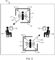
- Figure 3 illustrates the transportation vehicle 100 comprising more than one shield 12 and 22 configured to surround the Bluetooth beacons 11 and 21 respectively.
- the shield 12 has the opening 13 and the shield 22 has an opening 23, wherein the opening 13 and 23 are shaped to limit the transmission of radio frequency signals to predetermined directions 14a and 24a respectively.
- the shield 12 surrounding the Bluetooth beacon 11 is placed above the seated position 16a so as to guide the radio frequency signals downwards to the predetermined direction 14a (pointing towards the seated position 16a) and block the transmission of radio frequency signals in substantially X/Y or transverse directions that are substantially perpendicular to the predetermined direction 14a.
- the shield 22 surrounding the Bluetooth beacon 21 is placed below the seated positions 16b so as to guide the radio frequency signals upwards to the predetermined direction 24a (pointing towards the seated position 16b) and block the transmission of radio frequency signals in substantially X/Y or transverse directions that are substantially perpendicular to the predetermined direction 24a.
- the shield 12 is shaped to block the transmission of radio frequency signals in directions (for example, 14b, 14c, 14d) other than the predetermined direction 14a and the shield 22 is shaped to block the transmission of radio frequency signals in directions (for example, 24b, 24c, 24d) other than the predetermined direction 24a.
- the opening 13 allows communication between the electronic device 15a and the Bluetooth beacon 11 and the opening 23 allows communication between the electronic device 15b and the Bluetooth beacon 21, thereby accurately locating the electronic device 15a to the specific position/area and the electronic device 15b to another position/area.
- the shield 12 is configured to block the transmission of radio frequency signals to the electronic device 15b and the shield 22 is configured to block the transmission of radio frequency signals to the electronic device 15a.
- width 132 of the opening 13 is narrower than width 162 of a seated position 16 but not so small as to cause diffraction of the radio frequency signals. This helps in accurately locating and identifying customers down to a single seat in a transportation vehicle.
- width of the opening 13 is larger than the wavelength of the radio frequency signals to avoid the effects of diffraction.
- the shield 12 surrounding the Bluetooth beacon 11 can be placed or arranged inside the transportation vehicle in such a way so as to guide the radio frequency signals in a substantially Z or vertical direction and block the transmission of radio frequency signals in a substantially X/Y or transverse direction.
- the positions of Bluetooth beacon(s), shield(s) and seated position(s) in a transportation vehicle can be adjusted/arranged with respect to each other so as to direct the radio frequency signals emitted by the Bluetooth beacon towards a single seated position. This helps to locate and identify customers accurately down to a single seat and block the transmission of radio frequency signals to other seated positions. It is to be noted that the implementation of the present invention can easily be extended to more than two shields, more than two Bluetooth beacons and more than two seated positions.
- At least a portion of the luggage racks usually present in the transportation vehicle can be configured as the shield around the Bluetooth beacon to limit the transmission of radio frequency signals to predetermined direction on an almost cost-neutral basis.
- the Bluetooth beacon can be placed inside a metallic portion of the luggage rack such that the metallic portion at least partially surrounds the Bluetooth beacon. Therefore, the luggage rack usually placed above seated positions in the transportation vehicle can be designed in accordance with the present invention so as to guide the radio frequency signals from the Bluetooth beacon downwards to a predetermined direction (pointing towards a seated position) and block the transmission of radio frequency signals in a substantially X/Y or transverse direction (towards other seated positions).
- the present invention has a range of applications, such as, but not limited to, at-seat catering, revenue enforcement, ticket sales, etc.
- the invention can also be suitable to gain access to certain services or offerings in an environment where a plurality of positions are located in a specific seating zone or any other commercial zones, such as, but not limited to, offices, airports, lounges, restaurants, cruise, hospitals, etc.
Landscapes
- Engineering & Computer Science (AREA)
- Computer Networks & Wireless Communication (AREA)
- Signal Processing (AREA)
- Shielding Devices Or Components To Electric Or Magnetic Fields (AREA)
Abstract
The present invention relates to a transportation vehicle (100) provided with a shield (12, 22) configured to surround a Bluetooth beacon (11, 21). The present invention provides an arrangement in the transportation vehicle to increase the accuracy and/or resolution of the Bluetooth beacon through physical shielding. The improved arrangement may be used for an indoor positioning system in the transportation vehicle.
Description
- The presently disclosed subject matter relates generally to a transportation vehicle provided with a shield configured to surround a Bluetooth beacon.
- Bluetooth beacons broadcast radio frequency signals within a surrounding area and are used in indoor positioning applications. However, it is sometimes difficult to determine which beacon an electronic device is closest to when a high density of Bluetooth beacons are used. Indeed, the coverage of the Bluetooth beacon signal is prone to the problem of overlapping signals when high density of Bluetooth beacons are used simultaneously. This may lead to inaccurate detection of the location of the electronic device. Therefore, it is desired to increase resolution and/or accuracy of the Bluetooth beacons. Furthermore, resolution of the Bluetooth beacon becomes especially important in order to use the technology to locate and identify customers down to their respective seats in a transportation vehicle. So, it is also desired to find ways for accurately locating and identifying customers in a transportation vehicle using Bluetooth technology.
- The invention aims to address these needs by providing an arrangement in a transportation vehicle to increase the accuracy and/or resolution of a Bluetooth beacon. The improved arrangement may be used for an indoor positioning system in a transportation vehicle.
- These goals are achieved by a transportation vehicle according to a first object of the invention, said transportation vehicle comprising:
- a shield configured to at least partially surround a Bluetooth beacon, the shield having an opening shaped to limit the transmission of radio frequency signals from the Bluetooth beacon to a predetermined direction,
- wherein the shield is shaped to block the transmission of radio frequency signals in directions substantially perpendicular to that of the predetermined direction.
- According to specific embodiments of the invention, the shield comprises a metallic sheet.
- According to specific embodiments of the invention, at least a portion of the shield is made up of material capable of blocking the transmission of radio frequency signals.
- According to specific embodiments of the invention, the opening is shaped to minimize the effects of wave diffraction.
- According to specific embodiments of the invention, the predetermined direction points towards a specific position in the transportation vehicle.
- According to specific embodiments of the invention, the specific position is a seated position.
- According to specific embodiments of the invention, the opening faces towards the seated position.
- According to specific embodiments of the invention, width of the opening is narrower than width of the seated position.
- According to specific embodiments of the invention, the Bluetooth beacon and the shield are placed so as to guide radio frequency signals in a vertical direction.
- According to specific embodiments of the invention, the Bluetooth beacon and the shield are placed so as to guide radio frequency signals towards the specific position.
- According to specific embodiments of the invention, the Bluetooth beacon and the shield are placed above the seated position so as to guide radio frequency signals downwards.
- According to specific embodiments of the invention, the Bluetooth beacon and the shield are placed below the seated position so as to guide radio frequency signals upwards.
- According to specific embodiments of the invention, the Bluetooth beacon comprises a directional antenna.
- According to specific embodiments of the invention, the transportation vehicle is a train carriage.
- It is yet another object of the invention to provide a shield configured to at least partially surround the Bluetooth beacon, the shield having an opening shaped to limit the radio frequency signals emitted from the Bluetooth beacon to the predetermined direction(s)/sector, wherein the shield is shaped to block the transmission of radio frequency signals emitted from Bluetooth beacon in directions that are substantially perpendicular to the predetermined direction (s) .
- Various objects, features, aspects and advantages of the present disclosure will become more apparent from the following detailed description of preferred embodiments, along with the accompanying drawing figures in which like numerals represent like features.
- In order to understand the invention and to see how it can be carried out in practice, non-limiting examples and embodiments will now be described with reference to the accompanying drawings, in which:
-
Figure 1 is a representation of a shield configured to surround at least partially a Bluetooth beacon according to an embodiment of the invention; -
Figure 2 illustrates a transportation vehicle comprising the shield according to another embodiment(s) of the invention; -
Figure 3 illustrates the transportation vehicle comprising more than one shield according to another embodiment(s) of the invention; and -
Figure 4 illustrates a three-dimensional view of the shield and a seated position according to another embodiment(s) of the invention. - Aspects of the present invention are best understood by reference to the figures and description set forth herein. All the embodiments described herein will be better appreciated and understood when considered in conjunction with the following description and the accompanying drawings. It should be understood, however, that the following descriptions, while indicating preferred, different embodiments, examples and numerous specific details thereof, are given by way of illustration and not of limitation. Many changes and modifications may be made within the scope herein without departing from the spirit and scope thereof, and the present invention herein include all such modifications. It is to be understood that the embodiments may or may not overlap with each other. Thus, part of one embodiment, or specific embodiments thereof, may or may not fall within the ambit of another, or specific embodiments thereof, and vice-versa. Similarly, it is to be understood that a feature described with respect to one embodiment may be combined with any feature described in relation to another embodiment.
- According to an embodiment of the invention,
Figure 1 illustrates ashield 12 configured to at least partially surround a Bluetoothbeacon 11. Theshield 12 has an opening 13 shaped to limit the transmission of radio frequency signals emitted from the Bluetooth beacon to apredetermined direction 14a. Further, theshield 12 is shaped to block the transmission of radio frequency signals in directions that are substantially perpendicular to thepredetermined direction 14a. The Bluetoothbeacon 11 further comprises an antenna (not shown) that emits radio frequency signals. - According to another embodiment of the invention, the
shield 12 is shaped to block the transmission of radio frequency signals in directions (for example, 14b, 14c, 14d) other than thepredetermined direction 14a. - According to another embodiment of the invention, the
opening 13 allows communication between anelectronic device 15 and the Bluetoothbeacon 11 thereby accurately locating theelectronic device 15 to a specific position/area. In one example, size of theopening 13 can be adjustable to tune and/or limit the transmission of radio frequency signals emitted from the Bluetooth beacon to the specific position/area. In another specific example, size of theopening 13 can be adjusted in such a way so as to minimize the effects of wave diffraction. - The
electronic device 15 can be any electronic device such as, but not limited to, mobile phone, tablet, laptop, wearable device, etc. - According to another embodiment of the invention, the opening 13 can be of different shapes suitable to limit the transmission of radio frequency signals from the Bluetooth
beacon 11 to thepredetermined direction 14a. - According to another embodiment of the invention, the
shield 12 is a hollow structure having the opening/gap 13. In one specific example, this hollow structure can resemble any three-dimensional shape, such as, but not limited to, cuboid, cube, sphere, funnel, hemi-sphere, arc-shaped, cone, etc., having the opening/gap 13. - According to another embodiment of the invention, at least a portion of the
shield 12 is made up of material capable of blocking the transmission of radio frequency signals emitted by the Bluetoothbeacon 11. In one example, at least a portion of theshield 12 is made up of suitable material capable of absorbing or reflecting the radio frequency signals emitted by the Bluetoothbeacon 11. Further, depth/thickness of the material can vary based on its properties. In another example, inner region and outer region of theshield 12 can be made up of same or different material. In another example, at least a portion of theshield 12 can be made up of materials, such as, but not limited to, aluminum, magnesium, copper, steel, conductive metal including ultra-conductive film or coating, metal alloy, ceramics, or plastics infused with conductive elements, conductive compounds, and/or conductive mixtures. In another example, at least a portion of theshield 12 can be made up of material comprising a polymer-based matrix material or carbon fiber-filled matrix material including metal filaments dispersed in a matrix to form a polymer or carbon fiber composite material. In another example, theshield 12 comprises a metallic sheet. In another example, metallic meshes/fabrics and/or conductive metallic paints and finishes can be applied to one or more portions of the shield 12 (internally or externally). - According to another embodiment of the invention, a plurality of patterns or structures can be formed on at least a portion of inner region of the
shield 12 to block the transmission of radio frequency signals emitted from theBluetooth beacon 11 by either absorption and/or reflection. - According to another embodiment of the invention, the
Bluetooth beacon 11 emits radio frequency signals when connected to a power supply component (not shown) that can be placed inside or outside theshield 12. The power supply component may comprise a battery or an electrical contact connected to an external power supply device. - According to another embodiment of the invention, the
Bluetooth beacon 11 comprises a directional antenna configured to transmit the radio frequency signals to a particular direction. - According to another embodiment of the invention,
Figure 2 illustrates atransportation vehicle 100 comprising theshield 12 configured to at least partially surround theBluetooth beacon 11. Thetransportation vehicle 100 further comprises a plurality of seatedpositions shield 12 has theopening 13 shaped to limit the transmission of radio frequency signals to thepredetermined direction 14a. Thepredetermined direction 14a points towards a specific position in thetransportation vehicle 100. In one specific example, the specific position is one of the plurality of seatedpositions transportation vehicle 100. - According to another embodiment of the invention, the
opening 13 allows communication between theelectronic device 15a and theBluetooth beacon 11 thereby accurately locating theelectronic device 15a to the specific position/area. Further, theshield 12 is configured to block the transmission of radio frequency signals to theelectronic device 15b in another position/area. - According to another embodiment of the invention, the
opening 13 faces towards the seatedposition 16a. - According to another embodiment of the invention, examples of the transportation vehicle include, such as, but not limited to, aircraft, boat, train, car, bus, tram etc. or a compartment thereof. In one specific example, the transportation vehicle is a train carriage or an aircraft cabin.
- According to another embodiment of the invention,
Figure 3 illustrates thetransportation vehicle 100 comprising more than oneshield Bluetooth beacons shield 12 has theopening 13 and theshield 22 has anopening 23, wherein theopening predetermined directions shield 12 surrounding theBluetooth beacon 11 is placed above the seatedposition 16a so as to guide the radio frequency signals downwards to thepredetermined direction 14a (pointing towards the seatedposition 16a) and block the transmission of radio frequency signals in substantially X/Y or transverse directions that are substantially perpendicular to thepredetermined direction 14a. Theshield 22 surrounding theBluetooth beacon 21 is placed below the seatedpositions 16b so as to guide the radio frequency signals upwards to thepredetermined direction 24a (pointing towards the seatedposition 16b) and block the transmission of radio frequency signals in substantially X/Y or transverse directions that are substantially perpendicular to thepredetermined direction 24a. - According to another embodiment of the invention, the
shield 12 is shaped to block the transmission of radio frequency signals in directions (for example, 14b, 14c, 14d) other than thepredetermined direction 14a and theshield 22 is shaped to block the transmission of radio frequency signals in directions (for example, 24b, 24c, 24d) other than thepredetermined direction 24a. - According to another embodiment of the invention, the
opening 13 allows communication between theelectronic device 15a and theBluetooth beacon 11 and theopening 23 allows communication between theelectronic device 15b and theBluetooth beacon 21, thereby accurately locating theelectronic device 15a to the specific position/area and theelectronic device 15b to another position/area. Further, theshield 12 is configured to block the transmission of radio frequency signals to theelectronic device 15b and theshield 22 is configured to block the transmission of radio frequency signals to theelectronic device 15a. - According to another embodiment of the invention as shown in
Figure 4 ,width 132 of theopening 13 is narrower thanwidth 162 of a seatedposition 16 but not so small as to cause diffraction of the radio frequency signals. This helps in accurately locating and identifying customers down to a single seat in a transportation vehicle. In one specific example, width of theopening 13 is larger than the wavelength of the radio frequency signals to avoid the effects of diffraction. - According to another embodiment of the invention as shown in
Figure 4 , theshield 12 surrounding theBluetooth beacon 11 can be placed or arranged inside the transportation vehicle in such a way so as to guide the radio frequency signals in a substantially Z or vertical direction and block the transmission of radio frequency signals in a substantially X/Y or transverse direction. - In another embodiment of the invention, the positions of Bluetooth beacon(s), shield(s) and seated position(s) in a transportation vehicle can be adjusted/arranged with respect to each other so as to direct the radio frequency signals emitted by the Bluetooth beacon towards a single seated position. This helps to locate and identify customers accurately down to a single seat and block the transmission of radio frequency signals to other seated positions. It is to be noted that the implementation of the present invention can easily be extended to more than two shields, more than two Bluetooth beacons and more than two seated positions.
- In another embodiment of the invention, at least a portion of the luggage racks usually present in the transportation vehicle, can be configured as the shield around the Bluetooth beacon to limit the transmission of radio frequency signals to predetermined direction on an almost cost-neutral basis. For example, the Bluetooth beacon can be placed inside a metallic portion of the luggage rack such that the metallic portion at least partially surrounds the Bluetooth beacon. Therefore, the luggage rack usually placed above seated positions in the transportation vehicle can be designed in accordance with the present invention so as to guide the radio frequency signals from the Bluetooth beacon downwards to a predetermined direction (pointing towards a seated position) and block the transmission of radio frequency signals in a substantially X/Y or transverse direction (towards other seated positions).
- The present invention has a range of applications, such as, but not limited to, at-seat catering, revenue enforcement, ticket sales, etc. The invention can also be suitable to gain access to certain services or offerings in an environment where a plurality of positions are located in a specific seating zone or any other commercial zones, such as, but not limited to, offices, airports, lounges, restaurants, cruise, hospitals, etc.
- It will be appreciated that the above description has described and illustrated specific embodiments, arrangements or examples of the invention. However, it is apparent that the description is intended to cover any and all variations of various embodiments, examples and arrangements of the invention. Combinations of the above arrangements, and other arrangements not specifically described herein, will be apparent to those of skill in the art upon reviewing the above description. Therefore, it is intended that the disclosure not be limited to the particular arrangement(s) disclosed as the best mode contemplated for carrying out this invention, but that the invention will include all embodiments and arrangements falling within the scope of the appended claims.
Claims (14)
- A transportation vehicle (100), characterized in that it comprises
a shield (12, 22) configured to at least partially surround a Bluetooth beacon (11, 21), the shield having an opening shaped to limit the transmission of radio frequency signals from the Bluetooth beacon to a predetermined direction, wherein the shield is shaped to block the transmission of radio frequency signals in directions substantially perpendicular to that of the predetermined direction. - The transportation vehicle of claim 1, characterized in that the shield comprises a metallic sheet.
- The transportation vehicle of claim 1, characterized in that at least a portion of the shield is made up of material capable of blocking the transmission of radio frequency signals.
- The transportation vehicle of claim 1, characterized in that the opening is shaped to minimize the effects of wave diffraction.
- The transportation vehicle of claim 1, characterized in that the predetermined direction points towards a specific position in the transportation vehicle.
- The transportation vehicle of claim 5, characterized in that the specific position is a seated position.
- The transportation vehicle of claim 6, characterized in that the opening faces towards the seated position.
- The transportation vehicle of claim 6, characterized in that width of the opening is narrower than width of the seated position.
- The transportation vehicle of claim 1, characterized in that the Bluetooth beacon and the shield are placed so as to guide radio frequency signals in a vertical direction.
- The transportation vehicle of claim 5, characterized in that the Bluetooth beacon and the shield are placed so as to guide radio frequency signals towards the specific position.
- The transportation vehicle of claim 6, characterized in that the Bluetooth beacon and the shield are placed above the seated position so as to guide radio frequency signals downwards.
- The transportation vehicle of claim 1, characterized in that the Bluetooth beacon and the shield are placed below the seated position so as to guide radio frequency signals upwards.
- The transportation vehicle of claim 1, characterized in that the Bluetooth beacon comprises a directional antenna.
- The transportation vehicle of claim 1, characterized in that it is a train carriage.
Priority Applications (1)
| Application Number | Priority Date | Filing Date | Title |
|---|---|---|---|
| EP19169647.5A EP3726757A1 (en) | 2019-04-16 | 2019-04-16 | A transportation vehicle provided with a shield |
Applications Claiming Priority (1)
| Application Number | Priority Date | Filing Date | Title |
|---|---|---|---|
| EP19169647.5A EP3726757A1 (en) | 2019-04-16 | 2019-04-16 | A transportation vehicle provided with a shield |
Publications (1)
| Publication Number | Publication Date |
|---|---|
| EP3726757A1 true EP3726757A1 (en) | 2020-10-21 |
Family
ID=66217836
Family Applications (1)
| Application Number | Title | Priority Date | Filing Date |
|---|---|---|---|
| EP19169647.5A Withdrawn EP3726757A1 (en) | 2019-04-16 | 2019-04-16 | A transportation vehicle provided with a shield |
Country Status (1)
| Country | Link |
|---|---|
| EP (1) | EP3726757A1 (en) |
Citations (2)
| Publication number | Priority date | Publication date | Assignee | Title |
|---|---|---|---|---|
| US6222458B1 (en) * | 1999-11-15 | 2001-04-24 | Scott C. Harris | Automatic cell phone detection at a combustible delivery station |
| CN107402369A (en) * | 2016-05-18 | 2017-11-28 | 鸿富锦精密工业(深圳)有限公司 | Radio positioner |
-
2019
- 2019-04-16 EP EP19169647.5A patent/EP3726757A1/en not_active Withdrawn
Patent Citations (2)
| Publication number | Priority date | Publication date | Assignee | Title |
|---|---|---|---|---|
| US6222458B1 (en) * | 1999-11-15 | 2001-04-24 | Scott C. Harris | Automatic cell phone detection at a combustible delivery station |
| CN107402369A (en) * | 2016-05-18 | 2017-11-28 | 鸿富锦精密工业(深圳)有限公司 | Radio positioner |
Similar Documents
| Publication | Publication Date | Title |
|---|---|---|
| US11668817B2 (en) | Integrated digital active phased array antenna and wingtip collision avoidance system | |
| Malanowski et al. | Analysis of detection range of FM‐based passive radar | |
| US10050336B2 (en) | Integrated digital active phased array antenna and wingtip collision avoidance system | |
| CN212229163U (en) | Device for selectively reflecting incident microwave or millimeter wave signals | |
| Macnamara | Introduction to antenna placement and installation | |
| US6933881B2 (en) | Automotive radar | |
| US9213097B2 (en) | Aircraft comprising an onboard weather radar antenna provided with inclined panels | |
| EP2522051B1 (en) | Antenna beam control elements, systems, architectures, and methods for radar, communications, and other applications | |
| CN110764059B (en) | Method for transmitting and receiving vertical beam three-coordinate phased array radar | |
| O'Hagan et al. | Elevation pattern analysis of common passive bistatic radar illuminators of opportunity | |
| CN115407260B (en) | Electronic device with angular position detection capability | |
| De et al. | A novel approach towards the designing of an antenna for aircraft collision avoidance system | |
| CN111796276A (en) | A dual-active composite imaging method based on millimeter wave | |
| JP2005061905A (en) | Wind speed radar | |
| Aloi et al. | Printed DSRC antennas for enhanced gain coverage towards front and rear of vehicle for automotive applications | |
| JP2020195027A (en) | Antenna device | |
| Jang et al. | Array antenna design for passive coherent location systems with non-uniform array configurations | |
| JPH07128434A (en) | Navigation equipment and aircraft | |
| Welling et al. | An 120 GHz $8\times 8$ FMCW MIMO Radar System with 90° Biaxial FOV for Autonomous Navigation of UAVs in 3-D Space | |
| JP2023042216A (en) | Communication device | |
| Matuszewski | Method of radiolocation object shield zone calculation for ground jammer stations | |
| KR100822705B1 (en) | Phase Detection Direction Detection Antenna | |
| De et al. | Design and development of a unit element microstrip antenna for aircraft collision avoidance system | |
| US20250210855A1 (en) | Radome and method of design thereof | |
| KR102637612B1 (en) | 3d road network system for moving objects and method of securing road network |
Legal Events
| Date | Code | Title | Description |
|---|---|---|---|
| PUAI | Public reference made under article 153(3) epc to a published international application that has entered the european phase |
Free format text: ORIGINAL CODE: 0009012 |
|
| STAA | Information on the status of an ep patent application or granted ep patent |
Free format text: STATUS: THE APPLICATION HAS BEEN PUBLISHED |
|
| AK | Designated contracting states |
Kind code of ref document: A1 Designated state(s): AL AT BE BG CH CY CZ DE DK EE ES FI FR GB GR HR HU IE IS IT LI LT LU LV MC MK MT NL NO PL PT RO RS SE SI SK SM TR |
|
| AX | Request for extension of the european patent |
Extension state: BA ME |
|
| STAA | Information on the status of an ep patent application or granted ep patent |
Free format text: STATUS: THE APPLICATION IS DEEMED TO BE WITHDRAWN |
|
| 18D | Application deemed to be withdrawn |
Effective date: 20210422 |