EP3726736A1 - Small-cell movement detection - Google Patents
Small-cell movement detection Download PDFInfo
- Publication number
- EP3726736A1 EP3726736A1 EP20168653.2A EP20168653A EP3726736A1 EP 3726736 A1 EP3726736 A1 EP 3726736A1 EP 20168653 A EP20168653 A EP 20168653A EP 3726736 A1 EP3726736 A1 EP 3726736A1
- Authority
- EP
- European Patent Office
- Prior art keywords
- motion
- small cell
- cell apparatus
- radio
- sensing device
- Prior art date
- Legal status (The legal status is an assumption and is not a legal conclusion. Google has not performed a legal analysis and makes no representation as to the accuracy of the status listed.)
- Granted
Links
Images


Classifications
-
- H—ELECTRICITY
- H04—ELECTRIC COMMUNICATION TECHNIQUE
- H04W—WIRELESS COMMUNICATION NETWORKS
- H04W64/00—Locating users or terminals or network equipment for network management purposes, e.g. mobility management
- H04W64/003—Locating users or terminals or network equipment for network management purposes, e.g. mobility management locating network equipment
-
- H—ELECTRICITY
- H04—ELECTRIC COMMUNICATION TECHNIQUE
- H04B—TRANSMISSION
- H04B1/00—Details of transmission systems, not covered by a single one of groups H04B3/00 - H04B13/00; Details of transmission systems not characterised by the medium used for transmission
- H04B1/38—Transceivers, i.e. devices in which transmitter and receiver form a structural unit and in which at least one part is used for functions of transmitting and receiving
- H04B1/3805—Transceivers, i.e. devices in which transmitter and receiver form a structural unit and in which at least one part is used for functions of transmitting and receiving with built-in auxiliary receivers
-
- G—PHYSICS
- G01—MEASURING; TESTING
- G01P—MEASURING LINEAR OR ANGULAR SPEED, ACCELERATION, DECELERATION, OR SHOCK; INDICATING PRESENCE, ABSENCE, OR DIRECTION, OF MOVEMENT
- G01P1/00—Details of instruments
- G01P1/02—Housings
- G01P1/023—Housings for acceleration measuring devices
-
- G—PHYSICS
- G01—MEASURING; TESTING
- G01S—RADIO DIRECTION-FINDING; RADIO NAVIGATION; DETERMINING DISTANCE OR VELOCITY BY USE OF RADIO WAVES; LOCATING OR PRESENCE-DETECTING BY USE OF THE REFLECTION OR RERADIATION OF RADIO WAVES; ANALOGOUS ARRANGEMENTS USING OTHER WAVES
- G01S19/00—Satellite radio beacon positioning systems; Determining position, velocity or attitude using signals transmitted by such systems
- G01S19/01—Satellite radio beacon positioning systems transmitting time-stamped messages, e.g. GPS [Global Positioning System], GLONASS [Global Orbiting Navigation Satellite System] or GALILEO
- G01S19/13—Receivers
-
- H—ELECTRICITY
- H04—ELECTRIC COMMUNICATION TECHNIQUE
- H04W—WIRELESS COMMUNICATION NETWORKS
- H04W64/00—Locating users or terminals or network equipment for network management purposes, e.g. mobility management
- H04W64/006—Locating users or terminals or network equipment for network management purposes, e.g. mobility management with additional information processing, e.g. for direction or speed determination
-
- G—PHYSICS
- G01—MEASURING; TESTING
- G01P—MEASURING LINEAR OR ANGULAR SPEED, ACCELERATION, DECELERATION, OR SHOCK; INDICATING PRESENCE, ABSENCE, OR DIRECTION, OF MOVEMENT
- G01P13/00—Indicating or recording presence, absence, or direction, of movement
-
- H—ELECTRICITY
- H01—ELECTRIC ELEMENTS
- H01Q—ANTENNAS, i.e. RADIO AERIALS
- H01Q1/00—Details of, or arrangements associated with, antennas
- H01Q1/02—Arrangements for de-icing; Arrangements for drying-out ; Arrangements for cooling; Arrangements for preventing corrosion
-
- H—ELECTRICITY
- H01—ELECTRIC ELEMENTS
- H01Q—ANTENNAS, i.e. RADIO AERIALS
- H01Q1/00—Details of, or arrangements associated with, antennas
- H01Q1/12—Supports; Mounting means
- H01Q1/22—Supports; Mounting means by structural association with other equipment or articles
- H01Q1/24—Supports; Mounting means by structural association with other equipment or articles with receiving set
- H01Q1/241—Supports; Mounting means by structural association with other equipment or articles with receiving set used in mobile communications, e.g. GSM
- H01Q1/246—Supports; Mounting means by structural association with other equipment or articles with receiving set used in mobile communications, e.g. GSM specially adapted for base stations
-
- H—ELECTRICITY
- H04—ELECTRIC COMMUNICATION TECHNIQUE
- H04L—TRANSMISSION OF DIGITAL INFORMATION, e.g. TELEGRAPHIC COMMUNICATION
- H04L67/00—Network arrangements or protocols for supporting network services or applications
- H04L67/01—Protocols
- H04L67/12—Protocols specially adapted for proprietary or special-purpose networking environments, e.g. medical networks, sensor networks, networks in vehicles or remote metering networks
-
- Y—GENERAL TAGGING OF NEW TECHNOLOGICAL DEVELOPMENTS; GENERAL TAGGING OF CROSS-SECTIONAL TECHNOLOGIES SPANNING OVER SEVERAL SECTIONS OF THE IPC; TECHNICAL SUBJECTS COVERED BY FORMER USPC CROSS-REFERENCE ART COLLECTIONS [XRACs] AND DIGESTS
- Y04—INFORMATION OR COMMUNICATION TECHNOLOGIES HAVING AN IMPACT ON OTHER TECHNOLOGY AREAS
- Y04S—SYSTEMS INTEGRATING TECHNOLOGIES RELATED TO POWER NETWORK OPERATION, COMMUNICATION OR INFORMATION TECHNOLOGIES FOR IMPROVING THE ELECTRICAL POWER GENERATION, TRANSMISSION, DISTRIBUTION, MANAGEMENT OR USAGE, i.e. SMART GRIDS
- Y04S40/00—Systems for electrical power generation, transmission, distribution or end-user application management characterised by the use of communication or information technologies, or communication or information technology specific aspects supporting them
- Y04S40/18—Network protocols supporting networked applications, e.g. including control of end-device applications over a network
Definitions
- Communications using small-cell transceivers in wireless network systems can be affected by movement of the transceiver. In some systems, movement of even a few centimeters can cause enough of a signal impedance change to affect communication channels, for example, causing dropped calls or reducing data rates.
- a motion sensing device may be incorporated into a small cell apparatus to report movement of the cell to a central station for analysis. This may be particularly true when the cell is mounted on structures subject to movement including a mid-span installation on an outdoor cable, such as on the strand used to support wired network cabling. Such an installation may be subject to movement due to wind, other weather conditions, or nearby activity.
- the motion sensing device may include one or more accelerometers, a GPS receiver, optical sensors or combinations of these or others. Movement may be reported to a server for analysis and processing, including matching cell motion to call statistics. When a determination is made that movement of the small cell apparatus is causing service issues, the cell location may be stabilized or the apparatus may be remounted or moved.
- An aspect provides a small cell apparatus configured to detect and report motion, the small cell apparatus comprising: a housing including a mounting structure; a first radio coupled to the housing that transmits and receives signals with communication system subscriber units; a motion sensing device coupled to housing, wherein the motion sensing device includes at least one accelerometer that is mounted normal to a strand on which the small cell apparatus is mounted; and a second radio coupled to the housing and communicatively coupled to the motion sensing device, the second radio communicating data received from the motion sensing device to a remotely located analysis unit.
- the motion sensing device may include a satellite navigation receiver.
- the second radio may be operated by a battery provided exclusively for operating the second radio.
- the second radio may have subscriber identity module (SIM) card used in authentication of endpoints and encryption of payloads.
- SIM subscriber identity module
- the second radio may be activated responsive to a trigger signal received from the motion sensing device, the trigger signal associated with motion being detected at the motion sensing device.
- Another aspect provides a method of detecting motion in a small cell apparatus, the method comprising: mounting a housing of the small cell apparatus to a strand of a wired cabling system, the small cell apparatus in radio communication with at least one subscriber unit via a first radio coupled to the housing; sensing motion of the small cell apparatus to generate motion data; capturing the motion data; and communicating the motion data via a second radio for use in performance analysis of a communication system.
- the method may further comprise, powering the second radio via a battery.
- Sensing motion of the small cell apparatus may comprise sensing motion via an accelerometer.
- Sensing motion of the small cell apparatus may comprise sensing motion via a global positioning satellite system.
- the second radio may be an Internet of Things (IoT) device operating over a lightweight machine-to-machine protocol being one of Lightweight Machine-to-Machine (LwM2M), Narrowband Internet of Things (NB-IoT), Long Range spread spectrum (LoRa), or Differential Binary Phase Shift Keying (DBPSK).
- IoT Internet of Things
- LwM2M Lightweight Machine-to-Machine
- NB-IoT Narrowband Internet of Things
- LoRa Long Range spread spectrum
- DBPSK Differential Binary Phase Shift Keying
- Cellular telephone sites are traditionally mounted on towers or buildings that provide stable platforms for the antenna structures associated with the cell site.
- the relatively low frequencies of the cell sites such as 700 MHz, accommodate both coverage areas in the kilometers and an inherent insensitivity to antenna movement.
- the combination of lower power cell transmitters along with higher frequencies into the tens of GHz and their correspondingly shorter wavelengths may result in a greater sensitivity to cell/antenna motion. This may be particularly true in the case of beam-forming technology used to steer radio energy to a particular target device.
- a small cell apparatus may include a motion sensing device to measure and report movement of the small cell apparatus. This movement information may be used in analyzing the effects of cell movement on call quality of service. For example, measured cell movement may be correlated to quality measurements such as dropped calls, lost packets, packet retries, or data rate.
- FIG. 1 is an illustration of a simplified and exemplary embodiment of a small cell apparatus 110 showing a strand-mounting.
- a pole 102 may support multiple wired lines, including power transmission lines 104 and a small signal line 106.
- a small signal line 106 may be mounted 40 inches or more below the power transmission lines 104.
- the small signal line 106 may include wired (landline) telephone conductors, cable TV/Internet conductors, fiber optic lines, or other signal carriers that do not represent an electrocution risk.
- the small signal line 106 may be hung from a steel cable or similar support mechanism known as a strand 108.
- the strand 108 may be encased within a jacket (not depicted) holding the associated small signal line 106 while in other cases, the strand may be visibly separate from the small signal line 106.
- the small cell apparatus 110 may include a housing 112 with a mounting structure 114 that couples the apparatus 110 to, in this example, the strand 108.
- the housing 112 may be weather resistant to provide protection from the elements, especially rain, snow, or ice.
- the housing 112 may also provide interior mounting surfaces for the various components making up the small cell apparatus 110.
- the apparatus 110 may also include an antenna 116, although in some embodiments the antenna 116 may be internal to the housing 112.
- Various electronics 118 may be mounted inside the housing 112 as illustrated in Fig. 2 .
- the small cell apparatus 110 may include various mechanical, electrical, and electronic components as illustrated in Fig. 2 .
- a power supply 130 may supply power to the other components of the apparatus 110 and may include a battery or high value capacitor to maintain power at the apparatus 110 should external power be interrupted.
- a first radio 132 may support communication with subscriber units for voice and data communications in accordance with known standards such as 4G LTE, 5G, WiFi, etc.
- the first radio may operate on first frequency in accordance with the appropriate standard and local configuration.
- a backhaul communications device 134 may transport subscriber unit communication to and from a hub, switch, or router associated with completing a communication path to a destination service or device.
- a motion sensing device 136 may be configured to use one or more techniques to detect movement of the apparatus 110.
- the motion sensing device 136 is discussed in more detail below with respect to Fig. 3 .
- a second radio 138 may be used to transmit motion data from the motion sensing device 136 to a server or analysis center (not depicted).
- the second radio 138 may be integral to the motion sensing device 136.
- the second radio 138 may contain its own battery 140 for powering the unit, such as a long-life lithium ion battery that may power the second radio (and optionally, the corresponding sensors in the motion sensing device 136) for up to several years.
- the second radio 138, the entire motion sensing device 136, or both may be powered via the apparatus power supply 130.
- the second radio 138 may also include a subscriber identify module (SIM) 142 for use in identification of the motion sensing device 136 as well as for security purposes including key storage, authentication, and data encryption.
- SIM subscriber identify module
- the second radio may use a specialized protocol to optimize for efficiency, especially since the motion sensing device 136 may not require high data rates but in this application conservation of battery life may be important.
- Some protocols that may be useful in this application are lightweight machine-to-machine (LwM2M), narrowband Internet-of-Things (NB-IoT), long range (LoRa), or differential binary phase shift keying (DBPSK) from SigFox, etc.
- the motion data may be communicated via the backhaul communications device 134.
- a cooling device 144 may be used to cool the small cell apparatus 110, or in some cases, may be part of the motion sensing device 136 for providing cooling to the device 136. In some locations, particularly a strand mount in a desert climate, the apparatus 110 may be exposed to direct sun over a long period of time, requiring some form of cooling.
- the cooling device 144 may be passive, such as cooling fins, may be active, such as a fan, or may be a combination of both. In other embodiments, another form of cooling may be used, such as a circulating liquid.
- the motion sensing device 136 may include one or more accelerometers 150, 152 153.
- the accelerometers 150, 152, 153 may be mounted orthogonally to provide measurements in different axes. For example, in a strand-mounted apparatus, movement parallel to the strand 108 may be limited by the mounting structure 114 while movement perpendicular to the strand may occur due to any of the environmental conditions described above. For that reason, the one or more accelerometers 150, 152 may be mounted to detect motion normal to the strand.
- the motion sensing device 136 may include the third axis sensor 153, depending on the mounting arrangement and the influences for motion.
- Some prepackaged accelerometers include multi-axis sensors and may be suitable for this application.
- the accelerometers 150, 152, 153 may be mounted to the housing 112 or to an antenna 116 or an antenna support.
- a Global Navigation Satellite System (GNSS) 154 such as GPS or Glonass, may also be part of the motion sensing device 136. Signals received via the GNSS antenna 156 may be used to observe movement of the motion sensing device 136.
- GNSS Global Navigation Satellite System
- a vibration sensor 158 may be included in the motion sensing device 136. While the vibration sensor 158 may simply be another form of accelerometer, the vibration sensor 158 may be sensitive at a higher frequency so that, for example, harmonic motion at a higher frequency that that caused by simple wind sway may be detectable.
- an optical sensor 160 may be used to detect motion instead of or in conjunction with one or more of the other sensors described.
- the optical sensor may operate in the visible light band or may operate in a non-visible spectrum such as infrared.
- Optical processing maybe used to detect motion by comparing the image features of known fixed objects, such as a nearby building, to current images to detect a shift indicating movement.
- the optical sensor 160 may be directed to an object offline from any expected motion so that the shift in image may be more prominent. It is anticipated that in various embodiments, as few as one sensor up to all the sensors described or others may incorporated into the motion sensing apparatus 136.
- a processor 162 such as a single chip computer or other controller may collect data from the various sensors 150, 152, 153, 154, 158, 160 that are present in any given embodiment and transmit that data, via the second radio 138 for analysis.
- the motion sensing device 136 may be configured collect data at a given rate, such as every 500 milliseconds, and report the collected data periodically, such as once an hour.
- the motion sensing device 136 may only report motion data when a certain motion threshold is reached. In some embodiments, such a threshold may include a minimum amount of movement, a minimum duration of movement, or both.
- the motion sensing device 136 may be polled, for example, so that the external analysis service requests data only when errors associated with the cell apparatus 110 are observed.
- the unit may be independently powered by a battery 164. In other embodiments, the motion sensing device 136 may use external power.
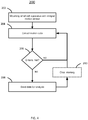
- Fig. 4 is a flowchart of a method 200 of detecting motion in a small cell apparatus 110.
- the small cell apparatus 110 may be coupled to a support using a mounting structure 114.
- the support may be a strand 108 of a small signal line.
- the apparatus 110 may be mounted to a mast or other structure subject to sway or vibration.
- the small cell apparatus 110 may include an integral motion sensing device 136 as well as at least one radio 132 that communicates with subscriber equipment.
- the motion sensing device 136 may collect data related to motion of the small cell apparatus 110.
- the data may be collected, at block 204, at a periodic rate or may be collected only when a predetermined motion threshold has been reached.
- a test is performed to determine if criteria for sending the motion data to a server for analysis has been met.
- the criteria may be or include expiration of a time period for reporting, being polled by the server for data, or when the motion data indicates a condition that merits monitoring. If the criteria is not met, execution may follow the 'no' branch back to block 204. If the criteria is satisfied, execution may follow the 'yes' branch to block 208, where the data may be sent to the server for analysis.
- any internal memory buffers may optionally be cleared at block 210 and execution may continue at block 204.
- a technical effect of the disclosed system is a capability of the small cell apparatus 110 to determine whether it is moving and report such movement to a server or analysis process.
- the ability to self-detect motion may provide valuable insight into data rate changes and errors associated with the apparatus 110.
- the need for this type of detailed information did not exist in previous generations of base station equipment because tower and building mounted transmitters/antenna, particularly those operating at much lower frequencies, were not subject to disruption due to movement.
- Both system operators and subscribers benefit from the ability to identify movement of a small cell apparatus 110 and from the corresponding ability to correlate that motion with transmission rate reductions and errors. Subscribers may experience fewer dropped calls and higher data rates while operators are able to meet quality of service (QoS) obligations and satisfy their subscribers.
- QoS quality of service
Landscapes
- Engineering & Computer Science (AREA)
- Computer Networks & Wireless Communication (AREA)
- Signal Processing (AREA)
- Radar, Positioning & Navigation (AREA)
- Remote Sensing (AREA)
- Physics & Mathematics (AREA)
- General Physics & Mathematics (AREA)
- Arrangements For Transmission Of Measured Signals (AREA)
Abstract
Description
- The background description provided herein is for the purpose of generally presenting the context of the disclosure. The work of the presently named inventors, to the extent it is described in this background section, as well as aspects of the description that may not otherwise qualify as prior art at the time of filing, are neither expressly nor impliedly admitted as prior art against the present disclosure.
- Communications using small-cell transceivers in wireless network systems can be affected by movement of the transceiver. In some systems, movement of even a few centimeters can cause enough of a signal impedance change to affect communication channels, for example, causing dropped calls or reducing data rates.
- In an embodiment, a motion sensing device may be incorporated into a small cell apparatus to report movement of the cell to a central station for analysis. This may be particularly true when the cell is mounted on structures subject to movement including a mid-span installation on an outdoor cable, such as on the strand used to support wired network cabling. Such an installation may be subject to movement due to wind, other weather conditions, or nearby activity. The motion sensing device may include one or more accelerometers, a GPS receiver, optical sensors or combinations of these or others. Movement may be reported to a server for analysis and processing, including matching cell motion to call statistics. When a determination is made that movement of the small cell apparatus is causing service issues, the cell location may be stabilized or the apparatus may be remounted or moved.
- An aspect provides a small cell apparatus configured to detect and report motion, the small cell apparatus comprising: a housing including a mounting structure; a first radio coupled to the housing that transmits and receives signals with communication system subscriber units; a motion sensing device coupled to housing, wherein the motion sensing device includes at least one accelerometer that is mounted normal to a strand on which the small cell apparatus is mounted; and a second radio coupled to the housing and communicatively coupled to the motion sensing device, the second radio communicating data received from the motion sensing device to a remotely located analysis unit.
- The motion sensing device may include a satellite navigation receiver.
- The second radio may be operated by a battery provided exclusively for operating the second radio.
- The second radio may have subscriber identity module (SIM) card used in authentication of endpoints and encryption of payloads.
- The second radio may be activated responsive to a trigger signal received from the motion sensing device, the trigger signal associated with motion being detected at the motion sensing device.
- Another aspect provides a method of detecting motion in a small cell apparatus, the method comprising: mounting a housing of the small cell apparatus to a strand of a wired cabling system, the small cell apparatus in radio communication with at least one subscriber unit via a first radio coupled to the housing; sensing motion of the small cell apparatus to generate motion data; capturing the motion data; and communicating the motion data via a second radio for use in performance analysis of a communication system.
- The method may further comprise, powering the second radio via a battery.
- Sensing motion of the small cell apparatus may comprise sensing motion via an accelerometer.
- Sensing motion of the small cell apparatus may comprise sensing motion via a global positioning satellite system.
- The second radio may be an Internet of Things (IoT) device operating over a lightweight machine-to-machine protocol being one of Lightweight Machine-to-Machine (LwM2M), Narrowband Internet of Things (NB-IoT), Long Range spread spectrum (LoRa), or Differential Binary Phase Shift Keying (DBPSK).
- The figures depict a preferred embodiment for purposes of illustration only. One skilled in the art may readily recognize from the following discussion that alternative embodiments of the structures and methods illustrated herein may be employed without departing from the principles described herein.
-
Fig. 1 is an illustration of an exemplary strand mounted small cell apparatus in accordance with the current disclosure; -
Fig. 2 is a block diagram of the internal components of an exemplary small cell apparatus in accordance with the current disclosure; -
Fig. 3 is a block diagram of an exemplary motion sensing device for use in the small cell apparatus ofFig. 2 ; and -
Fig. 4 is a flowchart of a method of detecting and sending motion data in the small cell apparatus ofFig. 2 . - Cellular telephone sites are traditionally mounted on towers or buildings that provide stable platforms for the antenna structures associated with the cell site. The relatively low frequencies of the cell sites, such as 700 MHz, accommodate both coverage areas in the kilometers and an inherent insensitivity to antenna movement. In more recent cellular system designs using a small cell apparatus, the combination of lower power cell transmitters along with higher frequencies into the tens of GHz and their correspondingly shorter wavelengths may result in a greater sensitivity to cell/antenna motion. This may be particularly true in the case of beam-forming technology used to steer radio energy to a particular target device.
- In the following discussion, although the actual interest is in the movement of an antenna, the construction of a small cell apparatus generally involves an integral antenna, so that movement of the small cell directly corresponds to movement of its antenna. In a case where the actual transceiver may be remote from its antenna, the following teachings may be applied to the antenna itself. However, for the sake of simplicity, the former example will be used in this description.
- In order to measure antenna motion, a small cell apparatus may include a motion sensing device to measure and report movement of the small cell apparatus. This movement information may be used in analyzing the effects of cell movement on call quality of service. For example, measured cell movement may be correlated to quality measurements such as dropped calls, lost packets, packet retries, or data rate.
-
Fig. 1 is an illustration of a simplified and exemplary embodiment of asmall cell apparatus 110 showing a strand-mounting. Apole 102 may support multiple wired lines, includingpower transmission lines 104 and asmall signal line 106. Typically, asmall signal line 106 may be mounted 40 inches or more below thepower transmission lines 104. Thesmall signal line 106 may include wired (landline) telephone conductors, cable TV/Internet conductors, fiber optic lines, or other signal carriers that do not represent an electrocution risk. Thesmall signal line 106 may be hung from a steel cable or similar support mechanism known as astrand 108. In some cases, thestrand 108 may be encased within a jacket (not depicted) holding the associatedsmall signal line 106 while in other cases, the strand may be visibly separate from thesmall signal line 106. - The
small cell apparatus 110 may include ahousing 112 with amounting structure 114 that couples theapparatus 110 to, in this example, thestrand 108. Thehousing 112 may be weather resistant to provide protection from the elements, especially rain, snow, or ice. Thehousing 112 may also provide interior mounting surfaces for the various components making up thesmall cell apparatus 110. Theapparatus 110 may also include anantenna 116, although in some embodiments theantenna 116 may be internal to thehousing 112.Various electronics 118 may be mounted inside thehousing 112 as illustrated inFig. 2 . - The
small cell apparatus 110 may include various mechanical, electrical, and electronic components as illustrated inFig. 2 . Apower supply 130 may supply power to the other components of theapparatus 110 and may include a battery or high value capacitor to maintain power at theapparatus 110 should external power be interrupted. - A
first radio 132 may support communication with subscriber units for voice and data communications in accordance with known standards such as 4G LTE, 5G, WiFi, etc. The first radio may operate on first frequency in accordance with the appropriate standard and local configuration. Abackhaul communications device 134 may transport subscriber unit communication to and from a hub, switch, or router associated with completing a communication path to a destination service or device. - A
motion sensing device 136 may be configured to use one or more techniques to detect movement of theapparatus 110. Themotion sensing device 136 is discussed in more detail below with respect toFig. 3 . - A
second radio 138 may be used to transmit motion data from themotion sensing device 136 to a server or analysis center (not depicted). In some embodiments, thesecond radio 138 may be integral to themotion sensing device 136. In some embodiments, thesecond radio 138 may contain itsown battery 140 for powering the unit, such as a long-life lithium ion battery that may power the second radio (and optionally, the corresponding sensors in the motion sensing device 136) for up to several years. In other cases, thesecond radio 138, the entiremotion sensing device 136, or both, may be powered via theapparatus power supply 130. Thesecond radio 138 may also include a subscriber identify module (SIM) 142 for use in identification of themotion sensing device 136 as well as for security purposes including key storage, authentication, and data encryption. - The second radio may use a specialized protocol to optimize for efficiency, especially since the
motion sensing device 136 may not require high data rates but in this application conservation of battery life may be important. Some protocols that may be useful in this application are lightweight machine-to-machine (LwM2M), narrowband Internet-of-Things (NB-IoT), long range (LoRa), or differential binary phase shift keying (DBPSK) from SigFox, etc. In some embodiments, the motion data may be communicated via thebackhaul communications device 134. - A
cooling device 144 may be used to cool thesmall cell apparatus 110, or in some cases, may be part of themotion sensing device 136 for providing cooling to thedevice 136. In some locations, particularly a strand mount in a desert climate, theapparatus 110 may be exposed to direct sun over a long period of time, requiring some form of cooling. Thecooling device 144 may be passive, such as cooling fins, may be active, such as a fan, or may be a combination of both. In other embodiments, another form of cooling may be used, such as a circulating liquid. - Turning to
Fig. 3 , a block diagram of an exemplarymotion sensing device 136 is discussed and described. Themotion sensing device 136 may include one ormore accelerometers accelerometers strand 108 may be limited by the mountingstructure 114 while movement perpendicular to the strand may occur due to any of the environmental conditions described above. For that reason, the one ormore accelerometers motion sensing device 136 may include thethird axis sensor 153, depending on the mounting arrangement and the influences for motion. Some prepackaged accelerometers include multi-axis sensors and may be suitable for this application. Theaccelerometers housing 112 or to anantenna 116 or an antenna support. A Global Navigation Satellite System (GNSS) 154, such as GPS or Glonass, may also be part of themotion sensing device 136. Signals received via theGNSS antenna 156 may be used to observe movement of themotion sensing device 136. Avibration sensor 158 may be included in themotion sensing device 136. While thevibration sensor 158 may simply be another form of accelerometer, thevibration sensor 158 may be sensitive at a higher frequency so that, for example, harmonic motion at a higher frequency that that caused by simple wind sway may be detectable. - In an embodiment, an
optical sensor 160 may be used to detect motion instead of or in conjunction with one or more of the other sensors described. The optical sensor may operate in the visible light band or may operate in a non-visible spectrum such as infrared. Optical processing maybe used to detect motion by comparing the image features of known fixed objects, such as a nearby building, to current images to detect a shift indicating movement. In an embodiment, theoptical sensor 160 may be directed to an object offline from any expected motion so that the shift in image may be more prominent. It is anticipated that in various embodiments, as few as one sensor up to all the sensors described or others may incorporated into themotion sensing apparatus 136. - A
processor 162, such as a single chip computer or other controller may collect data from thevarious sensors second radio 138 for analysis. In operation, themotion sensing device 136 may be configured collect data at a given rate, such as every 500 milliseconds, and report the collected data periodically, such as once an hour. In another embodiment, themotion sensing device 136 may only report motion data when a certain motion threshold is reached. In some embodiments, such a threshold may include a minimum amount of movement, a minimum duration of movement, or both. In other embodiments, themotion sensing device 136 may be polled, for example, so that the external analysis service requests data only when errors associated with thecell apparatus 110 are observed. The unit may be independently powered by abattery 164. In other embodiments, themotion sensing device 136 may use external power. -
Fig. 4 is a flowchart of amethod 200 of detecting motion in asmall cell apparatus 110. Atblock 202, thesmall cell apparatus 110 may be coupled to a support using a mountingstructure 114. In some embodiments, the support may be astrand 108 of a small signal line. In other embodiments, theapparatus 110 may be mounted to a mast or other structure subject to sway or vibration. Thesmall cell apparatus 110 may include an integralmotion sensing device 136 as well as at least oneradio 132 that communicates with subscriber equipment. - The
motion sensing device 136 may collect data related to motion of thesmall cell apparatus 110. The data may be collected, atblock 204, at a periodic rate or may be collected only when a predetermined motion threshold has been reached. In this exemplary embodiment, atblock 206, a test is performed to determine if criteria for sending the motion data to a server for analysis has been met. The criteria may be or include expiration of a time period for reporting, being polled by the server for data, or when the motion data indicates a condition that merits monitoring. If the criteria is not met, execution may follow the 'no' branch back to block 204. If the criteria is satisfied, execution may follow the 'yes' branch to block 208, where the data may be sent to the server for analysis. In an embodiment, after the current data is downloaded any internal memory buffers may optionally be cleared atblock 210 and execution may continue atblock 204. - A technical effect of the disclosed system is a capability of the
small cell apparatus 110 to determine whether it is moving and report such movement to a server or analysis process. The ability to self-detect motion may provide valuable insight into data rate changes and errors associated with theapparatus 110. The need for this type of detailed information did not exist in previous generations of base station equipment because tower and building mounted transmitters/antenna, particularly those operating at much lower frequencies, were not subject to disruption due to movement. - Both system operators and subscribers benefit from the ability to identify movement of a
small cell apparatus 110 and from the corresponding ability to correlate that motion with transmission rate reductions and errors. Subscribers may experience fewer dropped calls and higher data rates while operators are able to meet quality of service (QoS) obligations and satisfy their subscribers. - The figures depict preferred embodiments for purposes of illustration only. One skilled in the art will readily recognize from the following discussion that alternative embodiments of the structures and methods illustrated herein may be employed without departing from the principles described herein.
- Upon reading this disclosure, those of skill in the art will appreciate still additional alternative structural and functional designs for the systems and methods described herein through the disclosed principles herein. Thus, while particular embodiments and applications have been illustrated and described, it is to be understood that the disclosed embodiments are not limited to the precise construction and components disclosed herein. Various modifications, changes and variations, which will be apparent to those skilled in the art, may be made in the arrangement, operation and details of the systems and methods disclosed herein without departing from the spirit and scope defined in any appended claims.
- Representative features are set out in the following clauses, which stand alone or may be combined, in any combination, with one or more features disclosed in the text and/or drawings of the specification.
-
- 1. A small cell apparatus configured to detect and report motion, the small cell apparatus comprising:
- a housing including a mounting structure;
- a first radio coupled to the housing that transmits and receives signals with communication system subscriber units;
- a motion sensing device coupled to housing; and
- a second radio coupled housing and communicatively coupled to the motion sensing device, the second radio communicating data received from the motion sensing device to a remotely located analysis unit.
- 2. The small cell apparatus of aspect 1, wherein the housing is weather-resistant.
- 3. The small cell apparatus of aspect 1, wherein the motion sensing device includes at least one accelerometer.
- 4. The small cell apparatus of aspect 3, wherein the at least one accelerometer is mounted to detect motion normal to a strand on which the small cell apparatus is mounted.
- 5. The small cell apparatus of aspect 1, wherein the motion sensing device includes a satellite navigation receiver.
- 6. The small cell apparatus of aspect 1, wherein the second radio is battery operated.
- 7. The small cell apparatus of aspect 1, wherein the second radio has subscriber identity module (SIM) card used in authentication of endpoints and encryption of payloads.
- 8. The small cell apparatus of aspect 1, further comprising a cooling device.
- 9. The small cell apparatus of aspect 8, wherein the cooling device is one of a fan or a heatsink.
- 10. The small cell apparatus of aspect 8, wherein the cooling device is a combination fan and heatsink.
- 11. The small cell apparatus of aspect 1, wherein the second radio is activated responsive to a trigger signal received from the motion sensing device, the trigger signal associated with motion being detected at the motion sensing device.
- 12. A method of detecting motion in a small cell apparatus, the method comprising:
- mounting a housing of the small cell apparatus to a strand of a wired cabling system, the small cell apparatus in radio communication with at least one subscriber unit via a first radio coupled to the housing;
- sensing motion of the small cell apparatus to generate motion data;
- capturing the motion data; and
- communicating the motion data via a second radio for use in performance analysis of a communication system.
- 13. The method of aspect 12, further comprising, powering the second radio via a battery.
- 14. The method of aspect 12, further comprising cooling the second radio via one of an active and a passive cooling system.
- 15. The method of aspect 12, wherein the housing is a weather resistant housing.
- 16. The method of aspect 12, wherein sensing motion of the small cell apparatus comprises sensing motion via an accelerometer.
- 17. The method of aspect 12, wherein sensing motion of the small cell apparatus comprises sensing motion via a global positioning satellite system.
- 18. The method of aspect 12, wherein the second radio is an Internet of Things (IoT) device operating over a lightweight machine-to-machine protocol being one of LwM2M, NB-IoT, LoRa, or DBPSK.
- 19. A method of detecting motion in a small cell apparatus, the method comprising:
- providing the small cell apparatus with a first radio that communicates data with subscriber equipment and a second radio that communicates with a network service server;
- capturing a metric associated with motion in the small cell apparatus; and
- communicating the metric to the network service server via the second radio.
- 20. The method of aspect 19, wherein the metric includes a magnitude of the motion and at least one of a direction of the motion and a period of the motion.
- When used in this specification and claims, the terms "comprises" and "comprising" and variations thereof mean that the specified features, steps or integers are included. The terms are not to be interpreted to exclude the presence of other features, steps or components.
- The features disclosed in the foregoing description, or the following claims, or the accompanying drawings, expressed in their specific forms or in terms of a means for performing the disclosed function, or a method or process for attaining the disclosed result, as appropriate, may, separately, or in any combination of such features, be utilised for realising the invention in diverse forms thereof.
- Although certain example embodiments of the invention have been described, the scope of the appended claims is not intended to be limited solely to these embodiments. The claims are to be construed literally, purposively, and/or to encompass equivalents.
Claims (10)
- A small cell apparatus configured to detect and report motion, the small cell apparatus comprising:a housing including a mounting structure;a first radio coupled to the housing that transmits and receives signals with communication system subscriber units;a motion sensing device coupled to housing, wherein the motion sensing device includes at least one accelerometer that is mounted normal to a strand on which the small cell apparatus is mounted; anda second radio coupled to the housing and communicatively coupled to the motion sensing device, the second radio communicating data received from the motion sensing device to a remotely located analysis unit.
- The small cell apparatus of claim 1, wherein the motion sensing device includes a satellite navigation receiver.
- The small cell apparatus of any of claims 1-2, wherein the second radio is operated by a battery provided exclusively for operating the second radio.
- The small cell apparatus of any of claims 1-3, wherein the second radio has subscriber identity module (SIM) card used in authentication of endpoints and encryption of payloads.
- The small cell apparatus of any of claims 1-4, wherein the second radio is activated responsive to a trigger signal received from the motion sensing device, the trigger signal associated with motion being detected at the motion sensing device.
- A method of detecting motion in a small cell apparatus, the method comprising:mounting a housing of the small cell apparatus to a strand of a wired cabling system, the small cell apparatus in radio communication with at least one subscriber unit via a first radio coupled to the housing;sensing motion of the small cell apparatus to generate motion data;capturing the motion data; andcommunicating the motion data via a second radio for use in performance analysis of a communication system.
- The method of claim 6, further comprising, powering the second radio via a battery.
- The method of any of claims 6-7, wherein sensing motion of the small cell apparatus comprises sensing motion via an accelerometer.
- The method of any of claims 6-8, wherein sensing motion of the small cell apparatus comprises sensing motion via a global positioning satellite system.
- The method of of any of claims 6-9, wherein the second radio is an Internet of Things (IoT) device operating over a lightweight machine-to-machine protocol being one of Lightweight Machine-to-Machine (LwM2M), Narrowband Internet of Things (NB-IoT), Long Range spread spectrum (LoRa), or Differential Binary Phase Shift Keying (DBPSK).
Applications Claiming Priority (1)
| Application Number | Priority Date | Filing Date | Title |
|---|---|---|---|
| US16/388,980 US10694490B1 (en) | 2019-04-19 | 2019-04-19 | Small-cell movement detection |
Publications (3)
| Publication Number | Publication Date |
|---|---|
| EP3726736A1 true EP3726736A1 (en) | 2020-10-21 |
| EP3726736B1 EP3726736B1 (en) | 2025-03-12 |
| EP3726736C0 EP3726736C0 (en) | 2025-03-12 |
Family
ID=70277154
Family Applications (1)
| Application Number | Title | Priority Date | Filing Date |
|---|---|---|---|
| EP20168653.2A Active EP3726736B1 (en) | 2019-04-19 | 2020-04-08 | Small-cell movement detection |
Country Status (2)
| Country | Link |
|---|---|
| US (2) | US10694490B1 (en) |
| EP (1) | EP3726736B1 (en) |
Families Citing this family (1)
| Publication number | Priority date | Publication date | Assignee | Title |
|---|---|---|---|---|
| US10694490B1 (en) * | 2019-04-19 | 2020-06-23 | T-Mobile Usa, Inc. | Small-cell movement detection |
Citations (3)
| Publication number | Priority date | Publication date | Assignee | Title |
|---|---|---|---|---|
| US20110075646A1 (en) * | 2003-05-20 | 2011-03-31 | Belair Networks Inc. | Wireless system for communication |
| US20110309996A1 (en) * | 2010-06-21 | 2011-12-22 | Public Wireless, Inc. | Strand mountable antenna enclosure for wireless communication access system |
| US20170279494A1 (en) * | 2015-04-28 | 2017-09-28 | At&T Intellectual Property I, L.P. | Magnetic coupling device and methods for use therewith |
Family Cites Families (8)
| Publication number | Priority date | Publication date | Assignee | Title |
|---|---|---|---|---|
| US6374912B1 (en) * | 1998-12-30 | 2002-04-23 | Lucent Technologies | Deep drawn enclosure with integrated heatsink and fastening details |
| WO2006058341A2 (en) * | 2004-11-29 | 2006-06-01 | Sanmina-Sci Corporation | System and method for base station heat dissipation using chimneys |
| WO2008116168A1 (en) * | 2007-03-21 | 2008-09-25 | Jadi, Inc. | Navigation unit and base station |
| US8249553B2 (en) * | 2008-03-04 | 2012-08-21 | Alcatel Lucent | System and method for securing a base station using SIM cards |
| US9414188B2 (en) * | 2014-09-18 | 2016-08-09 | Qualcomm Incorporated | Location assistance information determination |
| CN105722094B (en) * | 2014-12-03 | 2019-12-06 | 索尼公司 | Method for interference coordination between small cells and wireless communication equipment |
| US10667232B2 (en) * | 2018-01-12 | 2020-05-26 | Idosens | Wireless computer network and method for locating a node in said network |
| US10694490B1 (en) * | 2019-04-19 | 2020-06-23 | T-Mobile Usa, Inc. | Small-cell movement detection |
-
2019
- 2019-04-19 US US16/388,980 patent/US10694490B1/en active Active
-
2020
- 2020-04-08 EP EP20168653.2A patent/EP3726736B1/en active Active
- 2020-04-29 US US16/861,436 patent/US11012968B2/en active Active
Patent Citations (3)
| Publication number | Priority date | Publication date | Assignee | Title |
|---|---|---|---|---|
| US20110075646A1 (en) * | 2003-05-20 | 2011-03-31 | Belair Networks Inc. | Wireless system for communication |
| US20110309996A1 (en) * | 2010-06-21 | 2011-12-22 | Public Wireless, Inc. | Strand mountable antenna enclosure for wireless communication access system |
| US20170279494A1 (en) * | 2015-04-28 | 2017-09-28 | At&T Intellectual Property I, L.P. | Magnetic coupling device and methods for use therewith |
Also Published As
| Publication number | Publication date |
|---|---|
| US20200337016A1 (en) | 2020-10-22 |
| US11012968B2 (en) | 2021-05-18 |
| EP3726736B1 (en) | 2025-03-12 |
| EP3726736C0 (en) | 2025-03-12 |
| US10694490B1 (en) | 2020-06-23 |
Similar Documents
| Publication | Publication Date | Title |
|---|---|---|
| US11686879B2 (en) | Distributed weather monitoring system | |
| US9618613B2 (en) | Radio communication apparatus, radio communication method, and radio communication system | |
| US7127213B2 (en) | Error correlation for wireless networks | |
| CN102401645B (en) | Outdoor antenna attitude detection apparatus and detection method | |
| KR101565350B1 (en) | Method and apparatus for mapping operating parameter in coverage area of wireless network | |
| US20120083289A1 (en) | Method, device and system for determining position information | |
| CN106550323B (en) | Method for determining the geographical position of a device | |
| KR101421170B1 (en) | Real time location system by using the tag node based on wi-fi | |
| EP4032164A1 (en) | System for monitoring a power distribution network and methods of building and performing operations on such system | |
| US11012968B2 (en) | Small-cell movement detection | |
| KR100865855B1 (en) | Apparatus and Method for Shadow Area Analysis | |
| WO2018060545A1 (en) | Positioning | |
| US11006297B2 (en) | Wireless remote monitoring system and data collection and control and method of using the same | |
| US11570613B2 (en) | Methods and apparatus for determining and using enclosure state information | |
| US20220205781A1 (en) | System and method for monitoring tilt of a structure | |
| KR20120069300A (en) | Underwater information collection apparatus capable of moving on the water | |
| CN117793781A (en) | Wireless signal processing systems and methods | |
| WO2023161650A1 (en) | Utility pole monitoring | |
| CN117470296A (en) | Communication sensing system, tower sensing device and antenna sensing device | |
| KR102175576B1 (en) | LoRa base ship position measurement system and measurement method | |
| KR100869146B1 (en) | Disaster prevention network system and method using weather report tower using WiMAX communication method | |
| KR100820301B1 (en) | Weather report tower using WiMAX communication | |
| RU115109U1 (en) | PERSONNEL AND CARGO MONITORING SYSTEM BASED ON A SELF-ORGANIZING WIRELESS NETWORK | |
| US20260128503A1 (en) | Base station antenna system | |
| CN111010309A (en) | Ad-hoc network-based equipment monitoring management method, electronic equipment and storage medium |
Legal Events
| Date | Code | Title | Description |
|---|---|---|---|
| PUAI | Public reference made under article 153(3) epc to a published international application that has entered the european phase |
Free format text: ORIGINAL CODE: 0009012 |
|
| STAA | Information on the status of an ep patent application or granted ep patent |
Free format text: STATUS: THE APPLICATION HAS BEEN PUBLISHED |
|
| AK | Designated contracting states |
Kind code of ref document: A1 Designated state(s): AL AT BE BG CH CY CZ DE DK EE ES FI FR GB GR HR HU IE IS IT LI LT LU LV MC MK MT NL NO PL PT RO RS SE SI SK SM TR |
|
| AX | Request for extension of the european patent |
Extension state: BA ME |
|
| STAA | Information on the status of an ep patent application or granted ep patent |
Free format text: STATUS: REQUEST FOR EXAMINATION WAS MADE |
|
| 17P | Request for examination filed |
Effective date: 20210401 |
|
| RBV | Designated contracting states (corrected) |
Designated state(s): AL AT BE BG CH CY CZ DE DK EE ES FI FR GB GR HR HU IE IS IT LI LT LU LV MC MK MT NL NO PL PT RO RS SE SI SK SM TR |
|
| STAA | Information on the status of an ep patent application or granted ep patent |
Free format text: STATUS: EXAMINATION IS IN PROGRESS |
|
| 17Q | First examination report despatched |
Effective date: 20220304 |
|
| GRAP | Despatch of communication of intention to grant a patent |
Free format text: ORIGINAL CODE: EPIDOSNIGR1 |
|
| STAA | Information on the status of an ep patent application or granted ep patent |
Free format text: STATUS: GRANT OF PATENT IS INTENDED |
|
| INTG | Intention to grant announced |
Effective date: 20241011 |
|
| GRAS | Grant fee paid |
Free format text: ORIGINAL CODE: EPIDOSNIGR3 |
|
| GRAA | (expected) grant |
Free format text: ORIGINAL CODE: 0009210 |
|
| STAA | Information on the status of an ep patent application or granted ep patent |
Free format text: STATUS: THE PATENT HAS BEEN GRANTED |
|
| AK | Designated contracting states |
Kind code of ref document: B1 Designated state(s): AL AT BE BG CH CY CZ DE DK EE ES FI FR GB GR HR HU IE IS IT LI LT LU LV MC MK MT NL NO PL PT RO RS SE SI SK SM TR |
|
| REG | Reference to a national code |
Ref country code: GB Ref legal event code: FG4D |
|
| REG | Reference to a national code |
Ref country code: CH Ref legal event code: EP |
|
| REG | Reference to a national code |
Ref country code: DE Ref legal event code: R096 Ref document number: 602020047495 Country of ref document: DE |
|
| REG | Reference to a national code |
Ref country code: IE Ref legal event code: FG4D |
|
| U01 | Request for unitary effect filed |
Effective date: 20250321 |
|
| U07 | Unitary effect registered |
Designated state(s): AT BE BG DE DK EE FI FR IT LT LU LV MT NL PT RO SE SI Effective date: 20250327 |
|
| U20 | Renewal fee for the european patent with unitary effect paid |
Year of fee payment: 6 Effective date: 20250331 |
|
| PG25 | Lapsed in a contracting state [announced via postgrant information from national office to epo] |
Ref country code: RS Free format text: LAPSE BECAUSE OF FAILURE TO SUBMIT A TRANSLATION OF THE DESCRIPTION OR TO PAY THE FEE WITHIN THE PRESCRIBED TIME-LIMIT Effective date: 20250612 |
|
| PG25 | Lapsed in a contracting state [announced via postgrant information from national office to epo] |
Ref country code: ES Free format text: LAPSE BECAUSE OF FAILURE TO SUBMIT A TRANSLATION OF THE DESCRIPTION OR TO PAY THE FEE WITHIN THE PRESCRIBED TIME-LIMIT Effective date: 20250312 |
|
| PG25 | Lapsed in a contracting state [announced via postgrant information from national office to epo] |
Ref country code: NO Free format text: LAPSE BECAUSE OF FAILURE TO SUBMIT A TRANSLATION OF THE DESCRIPTION OR TO PAY THE FEE WITHIN THE PRESCRIBED TIME-LIMIT Effective date: 20250612 |
|
| PG25 | Lapsed in a contracting state [announced via postgrant information from national office to epo] |
Ref country code: HR Free format text: LAPSE BECAUSE OF FAILURE TO SUBMIT A TRANSLATION OF THE DESCRIPTION OR TO PAY THE FEE WITHIN THE PRESCRIBED TIME-LIMIT Effective date: 20250312 |
|
| PG25 | Lapsed in a contracting state [announced via postgrant information from national office to epo] |
Ref country code: GR Free format text: LAPSE BECAUSE OF FAILURE TO SUBMIT A TRANSLATION OF THE DESCRIPTION OR TO PAY THE FEE WITHIN THE PRESCRIBED TIME-LIMIT Effective date: 20250613 |
|
| PG25 | Lapsed in a contracting state [announced via postgrant information from national office to epo] |
Ref country code: SM Free format text: LAPSE BECAUSE OF FAILURE TO SUBMIT A TRANSLATION OF THE DESCRIPTION OR TO PAY THE FEE WITHIN THE PRESCRIBED TIME-LIMIT Effective date: 20250312 |
|
| PG25 | Lapsed in a contracting state [announced via postgrant information from national office to epo] |
Ref country code: PL Free format text: LAPSE BECAUSE OF FAILURE TO SUBMIT A TRANSLATION OF THE DESCRIPTION OR TO PAY THE FEE WITHIN THE PRESCRIBED TIME-LIMIT Effective date: 20250312 |
|
| PG25 | Lapsed in a contracting state [announced via postgrant information from national office to epo] |
Ref country code: CZ Free format text: LAPSE BECAUSE OF FAILURE TO SUBMIT A TRANSLATION OF THE DESCRIPTION OR TO PAY THE FEE WITHIN THE PRESCRIBED TIME-LIMIT Effective date: 20250312 |
|
| PG25 | Lapsed in a contracting state [announced via postgrant information from national office to epo] |
Ref country code: SK Free format text: LAPSE BECAUSE OF FAILURE TO SUBMIT A TRANSLATION OF THE DESCRIPTION OR TO PAY THE FEE WITHIN THE PRESCRIBED TIME-LIMIT Effective date: 20250312 |
|
| PG25 | Lapsed in a contracting state [announced via postgrant information from national office to epo] |
Ref country code: IS Free format text: LAPSE BECAUSE OF FAILURE TO SUBMIT A TRANSLATION OF THE DESCRIPTION OR TO PAY THE FEE WITHIN THE PRESCRIBED TIME-LIMIT Effective date: 20250712 |
|
| REG | Reference to a national code |
Ref country code: CH Ref legal event code: H13 Free format text: ST27 STATUS EVENT CODE: U-0-0-H10-H13 (AS PROVIDED BY THE NATIONAL OFFICE) Effective date: 20251125 |
|
| PG25 | Lapsed in a contracting state [announced via postgrant information from national office to epo] |
Ref country code: MC Free format text: LAPSE BECAUSE OF FAILURE TO SUBMIT A TRANSLATION OF THE DESCRIPTION OR TO PAY THE FEE WITHIN THE PRESCRIBED TIME-LIMIT Effective date: 20250312 |
|
| PLBE | No opposition filed within time limit |
Free format text: ORIGINAL CODE: 0009261 |
|
| STAA | Information on the status of an ep patent application or granted ep patent |
Free format text: STATUS: NO OPPOSITION FILED WITHIN TIME LIMIT |
|
| PG25 | Lapsed in a contracting state [announced via postgrant information from national office to epo] |
Ref country code: CH Free format text: LAPSE BECAUSE OF NON-PAYMENT OF DUE FEES Effective date: 20250430 |
|
| REG | Reference to a national code |
Ref country code: CH Ref legal event code: L10 Free format text: ST27 STATUS EVENT CODE: U-0-0-L10-L00 (AS PROVIDED BY THE NATIONAL OFFICE) Effective date: 20260121 |
|
| 26N | No opposition filed |
Effective date: 20251215 |
|
| GBPC | Gb: european patent ceased through non-payment of renewal fee |
Effective date: 20250612 |
|
| PG25 | Lapsed in a contracting state [announced via postgrant information from national office to epo] |
Ref country code: GB Free format text: LAPSE BECAUSE OF NON-PAYMENT OF DUE FEES Effective date: 20250612 |
|
| PG25 | Lapsed in a contracting state [announced via postgrant information from national office to epo] |
Ref country code: IE Free format text: LAPSE BECAUSE OF NON-PAYMENT OF DUE FEES Effective date: 20250408 |
|
| U20 | Renewal fee for the european patent with unitary effect paid |
Year of fee payment: 7 Effective date: 20260319 |