EP3726721A1 - Mmc submodule selection - Google Patents
Mmc submodule selection Download PDFInfo
- Publication number
- EP3726721A1 EP3726721A1 EP19170425.3A EP19170425A EP3726721A1 EP 3726721 A1 EP3726721 A1 EP 3726721A1 EP 19170425 A EP19170425 A EP 19170425A EP 3726721 A1 EP3726721 A1 EP 3726721A1
- Authority
- EP
- European Patent Office
- Prior art keywords
- voltage value
- value
- submodule
- valve
- shift
- Prior art date
- Legal status (The legal status is an assumption and is not a legal conclusion. Google has not performed a legal analysis and makes no representation as to the accuracy of the status listed.)
- Granted
Links
Images



Classifications
-
- H—ELECTRICITY
- H02—GENERATION; CONVERSION OR DISTRIBUTION OF ELECTRIC POWER
- H02M—APPARATUS FOR CONVERSION BETWEEN AC AND AC, BETWEEN AC AND DC, OR BETWEEN DC AND DC, AND FOR USE WITH MAINS OR SIMILAR POWER SUPPLY SYSTEMS; CONVERSION OF DC OR AC INPUT POWER INTO SURGE OUTPUT POWER; CONTROL OR REGULATION THEREOF
- H02M7/00—Conversion of AC power input into DC power output; Conversion of DC power input into AC power output
- H02M7/42—Conversion of DC power input into AC power output without possibility of reversal
- H02M7/44—Conversion of DC power input into AC power output without possibility of reversal by static converters
- H02M7/48—Conversion of DC power input into AC power output without possibility of reversal by static converters using discharge tubes with control electrode or semiconductor devices with control electrode
- H02M7/483—Converters with outputs that each can have more than two voltages levels
-
- H—ELECTRICITY
- H02—GENERATION; CONVERSION OR DISTRIBUTION OF ELECTRIC POWER
- H02M—APPARATUS FOR CONVERSION BETWEEN AC AND AC, BETWEEN AC AND DC, OR BETWEEN DC AND DC, AND FOR USE WITH MAINS OR SIMILAR POWER SUPPLY SYSTEMS; CONVERSION OF DC OR AC INPUT POWER INTO SURGE OUTPUT POWER; CONTROL OR REGULATION THEREOF
- H02M7/00—Conversion of AC power input into DC power output; Conversion of DC power input into AC power output
- H02M7/42—Conversion of DC power input into AC power output without possibility of reversal
- H02M7/44—Conversion of DC power input into AC power output without possibility of reversal by static converters
- H02M7/48—Conversion of DC power input into AC power output without possibility of reversal by static converters using discharge tubes with control electrode or semiconductor devices with control electrode
- H02M7/483—Converters with outputs that each can have more than two voltages levels
- H02M7/4833—Capacitor voltage balancing
-
- H—ELECTRICITY
- H02—GENERATION; CONVERSION OR DISTRIBUTION OF ELECTRIC POWER
- H02M—APPARATUS FOR CONVERSION BETWEEN AC AND AC, BETWEEN AC AND DC, OR BETWEEN DC AND DC, AND FOR USE WITH MAINS OR SIMILAR POWER SUPPLY SYSTEMS; CONVERSION OF DC OR AC INPUT POWER INTO SURGE OUTPUT POWER; CONTROL OR REGULATION THEREOF
- H02M7/00—Conversion of AC power input into DC power output; Conversion of DC power input into AC power output
- H02M7/42—Conversion of DC power input into AC power output without possibility of reversal
- H02M7/44—Conversion of DC power input into AC power output without possibility of reversal by static converters
- H02M7/48—Conversion of DC power input into AC power output without possibility of reversal by static converters using discharge tubes with control electrode or semiconductor devices with control electrode
- H02M7/483—Converters with outputs that each can have more than two voltages levels
- H02M7/4835—Converters with outputs that each can have more than two voltages levels comprising two or more cells, each including a switchable capacitor, the capacitors having a nominal charge voltage which corresponds to a given fraction of the input voltage, and the capacitors being selectively connected in series to determine the instantaneous output voltage
-
- H—ELECTRICITY
- H02—GENERATION; CONVERSION OR DISTRIBUTION OF ELECTRIC POWER
- H02M—APPARATUS FOR CONVERSION BETWEEN AC AND AC, BETWEEN AC AND DC, OR BETWEEN DC AND DC, AND FOR USE WITH MAINS OR SIMILAR POWER SUPPLY SYSTEMS; CONVERSION OF DC OR AC INPUT POWER INTO SURGE OUTPUT POWER; CONTROL OR REGULATION THEREOF
- H02M1/00—Details of apparatus for conversion
- H02M1/0048—Circuits or arrangements for reducing losses
- H02M1/0054—Transistor switching losses
-
- Y—GENERAL TAGGING OF NEW TECHNOLOGICAL DEVELOPMENTS; GENERAL TAGGING OF CROSS-SECTIONAL TECHNOLOGIES SPANNING OVER SEVERAL SECTIONS OF THE IPC; TECHNICAL SUBJECTS COVERED BY FORMER USPC CROSS-REFERENCE ART COLLECTIONS [XRACs] AND DIGESTS
- Y02—TECHNOLOGIES OR APPLICATIONS FOR MITIGATION OR ADAPTATION AGAINST CLIMATE CHANGE
- Y02B—CLIMATE CHANGE MITIGATION TECHNOLOGIES RELATED TO BUILDINGS, e.g. HOUSING, HOUSE APPLIANCES OR RELATED END-USER APPLICATIONS
- Y02B70/00—Technologies for an efficient end-user side electric power management and consumption
- Y02B70/10—Technologies improving the efficiency by using switched-mode power supplies [SMPS], i.e. efficient power electronics conversion e.g. power factor correction or reduction of losses in power supplies or efficient standby modes
-
- Y—GENERAL TAGGING OF NEW TECHNOLOGICAL DEVELOPMENTS; GENERAL TAGGING OF CROSS-SECTIONAL TECHNOLOGIES SPANNING OVER SEVERAL SECTIONS OF THE IPC; TECHNICAL SUBJECTS COVERED BY FORMER USPC CROSS-REFERENCE ART COLLECTIONS [XRACs] AND DIGESTS
- Y02—TECHNOLOGIES OR APPLICATIONS FOR MITIGATION OR ADAPTATION AGAINST CLIMATE CHANGE
- Y02E—REDUCTION OF GREENHOUSE GAS [GHG] EMISSIONS, RELATED TO ENERGY GENERATION, TRANSMISSION OR DISTRIBUTION
- Y02E60/00—Enabling technologies; Technologies with a potential or indirect contribution to GHG emissions mitigation
- Y02E60/60—Arrangements for transfer of electric power between AC networks or generators via a high voltage DC link [HVCD]
Definitions
- the present disclosure relates to a method for selecting one or more submodules of a valve of modular multilevel converter in order to generate a desired valve output voltage.
- High voltage direct current (HVDC) power transmission is a cost-effective way of transmitting electrical power over long distances.
- alternating current (AC) electrical power is converted to high voltage direct current (HVDC) for transmission over overhead or undersea cables to a destination.
- HVDC power is converted back to AC power for onward distribution to end-user sites via an electrical distribution network.
- Modular multilevel converters are commonly used for the conversion of power between HVDC and AC.
- MMCs are typically made up of a plurality of submodules, which are typically half-bridge circuits of the kind illustrated in Figure 1 , which can be selected or deselected (i.e. inserted or bypassed in the MMC) as required so as to produce a desired MMC output voltage.
- a typical submodule is shown generally at 100 in Figure 1 .
- the submodule 100 includes a first switching element, in the form of a first silicon insulated-gate bipolar transistor (IGBT) 102, connected in series with a second switching element, in the form of a second silicon IGBT 104.
- IGBT insulated-gate bipolar transistor
- a first freewheel diode 106 is connected in an inverse parallel configuration with the first IGBT 102, with its anode connected to an emitter of the first IGBT 102 and its cathode connected to a collector of the first IGBT 102.
- a second freewheel diode 108 is connected in an inverse parallel configuration with the second IGBT 104, with its anode connected to an emitter of the second IGBT 104 and its cathode connected to a collector of the second IGBT 104.
- the emitter of the first IGBT 102 is connected to the collector of the second IGBT 104.
- the collector of the first IGBT 102 is connected to a positive terminal of an energy storage element such as a capacitor 110, whilst the emitter of the second IGBT 104 is connected to a negative terminal of the energy storage element 110.
- the gates of the first and second IGBTs 102, 104 are connected to outputs of a controller 112, which is configured to generate control signals to switch the first and second IGBTs 102, 104 on and off in a predetermined sequence.
- a submodule output voltage V SM is equal to a voltage V C across the capacitor 110.
- the capacitor 110 will charge if the current I SM in the submodule 100 is positive, and will discharge if the current I SM is negative.
- the submodule When the first IGBT 102 is switched off and the second IGBT 104 is switched on, the submodule is in a bypassed state.
- the submodule output voltage V SM is zero and the voltage V C across the capacitor 110 remains constant; the capacitor 110 does not charge or discharge.
- An MMC typically includes a plurality of submodules connected in series on phase-legs of the MMC, as shown generally at 200 in Figure 2 .
- the MMC 200 is coupled to three-phase AC terminals.
- a first terminal 202 of the three-phase AC terminals is coupled to a first phase-leg 220 which has upper (top) and lower (bottom) arms.
- a second terminal 204 of the three-phase AC terminals is coupled to a second phase-leg 240, which has upper (top) and lower (bottom) arms.
- a third terminal 206 of the three-phase AC terminals is coupled to a third phase-leg 260, which also has upper (top) and lower (bottom) arms.
- the first phase-leg 220 of the MMC 200 includes a top arm 220 T having a first limb reactor 222 (e.g. an inductance or a series combination of an inductance and a resistance), a plurality of submodules 224 1 - 224 n (labelled in Figure 2 SM_TA 1 - SM_TA n , to denote submodules of phase-leg A, top arm) forming a first valve and a second limb reactor 226 (e.g.
- an inductance or a series combination of an inductance and a resistance connected in series between a node at a mid-point of the first phase-leg 220 that connects the first phase terminal 202 to the first phase-leg 220 and a positive DC bus 270.
- the first phase-leg 220 of the MMC 200 includes a bottom arm 220 B having a third limb reactor 232 (e.g. an inductance or a series combination of an inductance and a resistance), a plurality of submodules 234 1 - 234 n (labelled in Figure 2 SM_BA 1 - SM_BA n , to denote submodules of phase-leg A, bottom arm) forming a second valve and a fourth limb reactor 236 (e.g. an inductance or a series combination of an inductance and a resistance) connected in series between the mid-point node of the first phase-leg 220 and a negative DC bus 280.
- a third limb reactor 232 e.g. an inductance or a series combination of an inductance and a resistance
- a plurality of submodules 234 1 - 234 n labelled in Figure 2 SM_BA 1 - SM_BA n , to denote submodules of
- the second phase-leg 240 of the MMC 200 includes a top arm 240 T having a first limb reactor 242 (e.g. an inductance or a series combination of an inductance and a resistance), a plurality of submodules 244 1 - 244 n (labelled in Figure 2 SM_TB 1 - SM_TB n , to denote submodules of phase-leg B, top arm) forming a third valve and a second limb reactor 246 (e.g.
- an inductance or a series combination of an inductance and a resistance connected in series between a node at a mid-point of the second phase-leg 240 that connects the second phase terminal 204 to the second phase-leg 240 and the positive DC bus 270.
- the second phase-leg 240 of the MMC 200 includes a bottom arm 240 B having a third limb reactor 252 (e.g. an inductance or a series combination of an inductance and a resistance), a plurality of submodules 254 1 - 254 n (labelled in Figure 2 SM_BB 1 - SM_BB n , to denote submodules of phase-leg B, bottom arm) forming a fourth valve and a fourth limb reactor 256 (e.g. an inductance or a series combination of an inductance and a resistance) connected in series between the mid-point node of the second phase-leg 240 and the negative DC bus 280.
- a third limb reactor 252 e.g. an inductance or a series combination of an inductance and a resistance
- a plurality of submodules 254 1 - 254 n labelled in Figure 2 SM_BB 1 - SM_BB n , to denote submodules of phase
- the third phase-leg 260 of the MMC 200 includes a top arm 260 T having a first limb reactor 262 (e.g. an inductance or a series combination of an inductance and a resistance), a plurality of submodules 264 1 - 264 n (labelled in Figure 2 SM_TC 1 - SM_TC n , to denote submodules of phase-leg C, top arm) forming a fifth valve and a second limb reactor 266 (e.g.
- an inductance or a series combination of an inductance and a resistance connected in series between a node at a mid-point of the third phase-leg 260 that connects the third phase terminal 206 to the second phase-leg 260 and the positive DC bus 270.
- the third phase-leg 260 of the MMC 200 includes a bottom arm 260 B having a third limb reactor 272 (e.g. an inductance or a series combination of an inductance and a resistance), a plurality of submodules 274 1 - 274 n (labelled in Figure 2 SM_BC 1 - SM_BC n , to denote submodules of phase-leg C, bottom arm) forming a sixth valve and a fourth limb reactor 276 (e.g. an inductance or a series combination of an inductance and a resistance) connected in series between the mid-point node of the third phase-leg 260 and the negative DC bus 280.
- a third limb reactor 272 e.g. an inductance or a series combination of an inductance and a resistance
- a plurality of submodules 274 1 - 274 n labelled in Figure 2 SM_BC 1 - SM_BC n , to denote submodules of phase
- Each valve of the MMC also includes a plurality of first sensors configured to indicate a voltage value for each submodule of the valve and a second sensor configured to indicate a polarity or sign of a current in the valve.
- the first valve includes a plurality of first sensors 228 1 configured to indicate a voltage value for each submodule of the first valve and a second sensor 228 2 configured to indicate a polarity or sign of a current in the first valve.
- the second valve includes a plurality of first sensors 238 1 and a second sensor 238 2
- the third valve includes a plurality of first sensors 248 1 and a second sensor 248 2
- the fourth valve includes a plurality of first sensors 258 1 and a second sensor 258 2
- the fifth valve includes a plurality of first sensors 268 1 and a second sensor 268 2
- the sixth valve includes a plurality of first sensors 278 1 and a second sensor 278 2 .
- first and second sensors in Figure 2 is illustrative only, and that the first and second sensors for each valve can be positioned at any convenient location in the valve that would allow the first and second sensors to fulfil their respective voltage and current sensing functions.
- a limb reactor for the arm 220 T could be provided only between the first terminal 202 and the submodule 224 n , or only between the positive DC bus 270 and the submodule 224 1 , or could be split between the bottom limb reactor 222 and top limb reactor 226.
- Limb reactors for the arms 240 T , 260 T could be similarly positioned, whilst limb reactors for the arms 220 B , 240 B , 260 B may be provided only between the respective terminals 202, 204, 206 and the submodules 234 1 , 254 1 , 274 1 , or only between the negative DC bus 280 and the submodules 234 n , 254 n , 274 n , or split between the top limb reactors 232, 252, 272 and the bottom limb reactors 236, 256, 276.
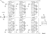
- a switching algorithm function 295 selectively activates (inserts) the submodules of each valve 220 T , 220 B , 240 T , 240 B , 260 T , 260 B according to a switching algorithm, as illustrated schematically in Figure 3 , as a DC voltage is applied across the positive and negative DC bus 270, 280, to selectively charge and discharge the energy storage elements 110 (e.g. capacitors) of each submodule.
- a switching algorithm function 295 selectively activates (inserts) the submodules of each valve 220 T , 220 B , 240 T , 240 B , 260 T , 260 B according to a switching algorithm, as illustrated schematically in Figure 3 , as a DC voltage is applied across the positive and negative DC bus 270, 280, to selectively charge and discharge the energy storage elements 110 (e.g. capacitors) of each submodule.
- a desired output voltage as defined by a respective control valve voltage reference signal V control_ref_PhaseTopA , V control_ref_PhaseBottomA , V control_ref_PhaseTopB , V control_ref_PhaseBottomB , V control_ref_PhaseTopC , V control_ref_PhaseBottomC , can be produced at each respective valve 220 T , 220 B , 240 T , 240 B , 260 T , 260 B , so as to generate a desired voltage at each of the AC terminals 202, 204, 206.
- Losses in an MMC-based scheme are typically distributed between a transformer on the AC side of the MMC, the MMC itself, and DC lines used to transmit power between stations. Within the MMC itself, approximately 35-40% of the total losses can be attributed to the commutation frequency of the submodules (i.e. the frequency with which the switching elements of the submodules are activated in order to insert or bypass the submodule in the MMC in order to meet a desired MMC output voltage), and 60-65% of the total losses can be attributed to conduction losses in the submodules.
- the invention provides a method for selecting submodules of a valve of modular multilevel converter in order to generate a desired valve output voltage, the method comprising: obtaining a voltage value for each submodule of the valve indicative of a voltage across an energy storage element of the submodule; for each submodule of the valve: if the submodule was previously selected: adding or subtracting a first shift voltage value to the obtained voltage value for the submodule based on a sign of a current in the valve to generate a modified voltage value for the submodule; and adding the submodule to a histogram according to the modified voltage value for the submodule; if the submodule was not previously selected: adding the submodule to a histogram according to the voltage value for the submodule; and selecting no submodules, one submodule or more than one submodules, based on their ranking in the histogram, to activate so as to generate the desired valve output voltage.
- the first shift voltage value may be a predefined fixed value, for example.
- the first shift voltage value may be added to the obtained voltage value. If the sign of the current in the valve is negative, the first shift voltage value may be subtracted from the obtained voltage value.
- the method may further comprise: if the sign of the current in the valve is negative and a voltage across the energy storage element of the submodule exceeds a predetermined threshold, adding a second shift voltage value to the obtained voltage value, as well as adding the first shift voltage value to the obtained voltage value, to generate the modified voltage value for the submodule; and if the sign of the current in the valve is positive and the voltage across the energy storage element of the submodule is less than a predetermined threshold, subtracting a second shift voltage value from the obtained voltage value, as well as subtracting the first shift voltage value from the obtained voltage value, to generate the modified voltage value for the submodule.
- the first shift voltage value may be a dynamic value that is calculated by comparing the voltage value for the submodule to a minimum or a maximum value threshold, based on the sign of a current in the valve.
- the first shift voltage value may be calculated by comparing the voltage value for the submodule to a minimum value threshold, and the first shift voltage value may be added to the obtained voltage value to generate the modified voltage value for the submodule; and if the sign of the current in the valve is positive, the first shift voltage value may be calculated by comparing the voltage value for the submodule to a maximum value threshold, and the first shift voltage value may be subtracted from the obtained voltage value to generate the modified voltage value for the submodule.
- the value of the minimum value threshold may be added to the obtained voltage value to generate the modified voltage value for the submodule. If the sign of the current in the valve is negative and the first shift voltage value exceeds the maximum value threshold, the value of the maximum value threshold may be added to the obtained voltage value to generate the modified voltage value for the submodule.
- the value of the minimum value threshold may be subtracted from the obtained voltage value to generate the modified voltage value for the submodule; and if the sign of the current in the valve is positive and the first shift voltage value exceeds the maximum value threshold, the value of the maximum value threshold may be subtracted from the obtained voltage value to generate the modified voltage value for the submodule.
- the method may further comprise: if the sign of the current in the valve is positive, comparing the obtained voltage value to a first threshold and: if the obtained voltage value is less than the first threshold, multiplying the first shift voltage value by a first gain value and subtracting the result of the multiplication from the obtained voltage value to generate the modified voltage value; if the obtained voltage value is greater than the first threshold, multiplying the first shift voltage value by a second gain value and subtracting the result of the multiplication from the obtained voltage value to generate the modified voltage value; and if the sign of the current in the valve is negative, comparing the obtained voltage value to a second threshold and: if the obtained voltage value is greater than the second threshold, multiplying the first shift voltage value by a third gain value and adding the result of the multiplication to the obtained voltage value to generate the modified voltage value; and if the obtained voltage value is less than the second threshold, multiplying the first shift voltage value by a fourth gain value and adding the result of the multiplication to the obtained voltage value to generate the modified voltage value.
- the method may further comprise: if the sign of the current in the valve is positive, prior to comparing the obtained voltage value to the first threshold, multiplying the first shift voltage value by a gain value to obtain a modified voltage shift value; and if the sign of the current in the valve is negative, prior to comparing the obtained voltage value to a second threshold, multiplying the first shift voltage value by the gain value to obtain a modified voltage shift value.
- the value of the minimum value threshold may be retained for subsequent use as the first shift voltage value. If the sign of the current in the valve is positive and the first shift voltage value exceeds a maximum value threshold, the value of the maximum value threshold may be retained for subsequent use as the first shift voltage value; if the sign of the current in the valve is negative and the first shift voltage value is below the minimum value threshold, the value of the minimum value threshold may be retained for subsequent use as the first shift voltage value; and if the sign of the current in the valve is negative and the first shift voltage value exceeds the maximum value threshold, the value of the maximum value threshold may be retained for subsequent use as the first shift voltage value.
- the invention provides a computer program comprising instructions which, when executed by a processing unit, causes the processing unit to perform the method of the first aspect.
- the invention provides a processing system comprising one or more processing units configured to execute the computer program of the second aspect.
- the invention provides a modular multilevel converter comprising: a plurality of valves, wherein each valve comprises: a plurality of submodules; a first sensor configured to indicate a voltage value for each submodule of the valve; a second sensor configured to indicate a polarity or sign of a current in the valve; and a control unit configured to select submodules of the valve of the modular multilevel converter in order to generate a desired valve output voltage, characterised in that said control unit is configured, upon receipt of indications from said first sensor and said second sensor, to: for each submodule of the valve: if the submodule was previously selected: add or subtract a first shift voltage value to the obtained voltage value for the submodule based on the sign of a current in the valve to generate a modified voltage value for the submodule; and add the submodule to a histogram according to the modified voltage value for the submodule; if the submodule was not previously selected:
- Each valve of the modular multilevel converter may comprise a limb reactor.
- the limb reactor may comprise an inductance or a series combination of an inductance and a resistance.
- the present disclosure relates to an improved switching algorithm for a modular multilevel converter (MMC) which selectively activates the submodules of the valves of the MMC in order to generate a desired valve output voltage defined by a control valve voltage reference signal, whilst limiting commutation frequency losses in the MMC.
- MMC modular multilevel converter
- a method (algorithm) performed by the switching algorithm function 295 for selecting submodules (either no submodules, one submodule, or more than one submodule) of a valve of an arm 220 T , 220 B , 240 T , 240 B , 260 T , 260 B of an MMC 200 to be activated (inserted) in order to generate a desired valve output voltage is shown generally at 400.
- a voltage value indicative of an instantaneous voltage across a storage element such as a capacitor 110 of each submodule of each valve of arms 220 T , 220 B , 240 T , 240 B , 260 T , 260 B is obtained.
- the voltage value may be obtained, for example, by measuring or estimating the voltage across the energy storage element 110 at a sample time, using the first sensor of the valve.
- a virtual voltage shift value which in this example is a predetermined fixed value
- the virtual shift voltage value is added to the obtained voltage value, such that the modified voltage value is greater than the obtained voltage value.
- the virtual shift voltage value is subtracted from the obtained voltage value, such that the modified voltage value is less than the obtained voltage value.
- each submodule in its respective histogram is based on the modified voltage value (where a modified voltage value has been generated) or the obtained voltage value (where no modified voltage value has been generated).
- the switching algorithm selects none, one or more submodules for each valve based on their rankings in the histogram (from lowest to highest or from highest to lowest) to be activated to generate a desired valve output voltage.
- the desired valve output voltage at each sample time is provided to the algorithm by the controller 290 as a reference voltage, and the switching algorithm selects none, one or more submodules for each valve at each sample time in order to create a voltage in the valve that is equal to the reference voltage provided by the controller.
- the submodules are selected in order from lowest to highest or highest to lowest, as a function of the sign of the current through the relevant arm(s).
- none, one or more of the submodules 224 1 - 224 n are selected, based upon their rankings in the histogram for the valve of arm 220 T , to be activated such that the valve output voltage generated by the combination of the selected submodules is equal to the specified valve output voltage V control_ref_PhaseTopA .
- none, one or more of the submodules 234 1 - 234 n are selected, based upon their rankings in the histogram for the valve of arm 220 B , to be activated such that the valve output voltage generated by the combination of the selected submodules is equal to the specified valve output voltage V control_ref_PhaseBottomA .
- Adding the virtual voltage value to, or subtracting the virtual voltage value from, the obtained voltage value for submodules that were selected at the preceding sample time alters the position of those submodules in the histogram (as compared to positioning the submodules in the histogram based upon their obtained voltage values alone) and increases the likelihood that they will be selected again at the current sample time, which reduces the need to insert or bypass submodules by changing the state of their switching elements.
- the switching frequency of the submodules in the MMC is reduced, leading to a reduction in switching losses in the MMC.
- Figure 5 is a flow diagram illustrating steps in an alternative method 500 (algorithm) for selecting submodules (either no submodules, one submodule, or more than one submodule) of a valve of an arm 220 T , 220 B , 240 T , 240 B , 260 T , 260 B of an MMC 200 to be activated in order to generate a desired valve output voltage.
- algorithm for selecting submodules (either no submodules, one submodule, or more than one submodule) of a valve of an arm 220 T , 220 B , 240 T , 240 B , 260 T , 260 B of an MMC 200 to be activated in order to generate a desired valve output voltage.
- a voltage value indicative of an instantaneous voltage across a storage element such as a capacitor 110 of each submodule of each valve of arms 220 T , 220 B , 240 T , 240 B , 260 T , 260 B is obtained.
- the voltage value may be obtained, for example, by measuring or estimating the voltage across the energy storage element 110 at a sample time, using the first sensor of the valve.
- one or more virtual voltage shift values are added to or subtracted from the obtained voltage value, depending on i) the sign or polarity of the instantaneous current flow (at the sample time) in the valve to which the submodule belongs and ii) the instantaneous voltage across the storage element of the submodule at the sample time.
- the first virtual voltage shift value may be a predetermined fixed value.
- the first virtual shift voltage value and a second virtual voltage shift value which may be a predetermined fixed value that is equal to the first virtual voltage shift value, are subtracted from the obtained submodule voltage to generate a modified voltage value.
- the first virtual voltage shift value may be a predetermined fixed value.
- the first virtual voltage shift value and a second virtual voltage shift value are added to the obtained submodule voltage to generate a modified voltage value.
- each submodule in its respective histogram is based on the modified voltage value (where a modified voltage value has been generated) or the obtained voltage value (where no modified voltage value has been generated).
- the switching algorithm selects none, one or more submodules for each valve based on their rankings in the histogram (from lowest to highest or from highest to lowest) to be activated to generate a desired valve output voltage.
- none, one or more of the submodules 224 1 - 224 n are selected, based upon their rankings in the histogram for the valve of arm 220 T , to be activated such that the valve output voltage generated by the combination of the selected submodules is equal to the specified valve output voltage V control_ref_PhaseTopA .
- none, one or more of the submodules 234 1 - 234 n are selected, based upon their rankings in the histogram for the valve of arm 220 B , to be activated such that the valve output voltage generated by the combination of the selected submodules is equal to the specified valve output voltage V control_ref_PhaseBottomA .
- adding the first virtual shift voltage value to, or subtracting the first virtual shift voltage value from, the obtained voltage value for submodules that were selected at the preceding sample time alters the position of those submodules in the histogram (as compared to positioning the submodules in the histogram based upon their obtained voltage values alone) and increases the likelihood that they will be selected again at the current sample time, which reduces the need to insert or bypass submodules by changing the state of their switching elements.
- the switching frequency of the submodules in the MMC is reduced, leading to a reduction in switching losses in the MMC.
- adding the second virtual voltage shift value to, or subtracting the second virtual voltage shift value from, the obtained voltage value increases the voltage band of the submodules, thereby further reducing the need for submodules to be inserted or bypassed in the MMC and thus further reducing the average commutation frequency of the submodules and associated switching losses in the MMC.
- a further alternative method for selecting submodules (either no submodules, one submodule, or more than one submodule) of a valve of an arm 220T, 220B, 240T, 240B, 260T, 260B of an MMC 200 to be activated in order to generate a desired valve output voltage, is shown generally at 600.
- a voltage value indicative of an instantaneous voltage across a storage element such as a capacitor 110 of each submodule of each valve of arms 220 T , 220 B , 240 T , 240 B , 260 T , 260 B is obtained.
- the voltage value may be obtained, for example, by measuring or estimating the voltage across the energy storage element 110 at a sample time, using the first sensor of the valve.
- a dynamic voltage shift value is generated based on i) the polarity or sign of instantaneous current flow in the valve to which the submodule belongs and ii) a threshold representing either a minimum or a maximum voltage across the storage element 110 of the submodule, depending upon the sign or polarity of instantaneous current flow in the valve.
- the instantaneous voltage across the storage element 110 of the submodule at the sample time is compared to a maximum voltage threshold representing a maximum voltage value across the storage element 110 of the submodule.
- a dynamic voltage shift value is obtained by calculating the difference between the maximum voltage threshold and the instantaneous voltage across the storage element 110 of the submodule at the sample time. If this dynamic voltage shift value is below a predefined maximum voltage shift value and above a predefined minimum voltage shift value, then the dynamic voltage shift value is subtracted from the obtained voltage value for the submodule to generate a modified voltage value for the submodule.
- the predefined minimum voltage shift value is subtracted from the obtained voltage value to generate the modified voltage value for the submodule. If the dynamic shift value meets or exceeds the predefined maximum voltage shift value, then the predefined maximum voltage shift value is subtracted from the obtained voltage value to generate the modified voltage value for the submodule.
- the instantaneous voltage across the storage element 110 of the submodule at the sample time is compared to a minimum voltage threshold representing a minimum voltage value across the storage element 110 of the submodule.
- a dynamic voltage shift value is obtained by calculating the difference between the instantaneous voltage across the submodule at the sample time and the minimum voltage threshold. If this dynamic voltage shift value is below the predefined maximum voltage shift value and above the predefined minimum voltage shift value, then the dynamic voltage shift value is added to the obtained voltage value for the submodule to generate a modified voltage value for the submodule.
- the predefined minimum voltage shift value is added to the obtained voltage value to generate the modified voltage value for the submodule. If the dynamic shift value meets or exceeds the predefined maximum voltage shift value, then the predefined maximum voltage shift value is added to the obtained voltage value to generate the modified voltage value for the submodule.
- each submodule in its respective histogram is based on the modified voltage value (where a modified voltage value has been generated) or the obtained voltage value (where no modified voltage value has been generated).
- the switching algorithm selects none, one or more submodules for each valve based on their rankings in the histogram (from lowest to highest or from highest to lowest) to be activated to generate a desired valve output voltage.
- none, one or more of the submodules 224 1 - 224 n are selected, based upon their rankings in the histogram for the valve of arm 220 T , to be activated such that the valve output voltage generated by the combination of the selected submodules is equal to the specified valve output voltage V control_ref_PhaseTopA .
- none, one or more of the submodules 234 1 - 234 n are selected, based upon their rankings in the histogram for valve 220 B , to be activated such that the valve output voltage generated by the combination of the selected submodules is equal to the specified valve output voltage V control_ref_PhaseBottomA .
- adding the shift voltage value to, or subtracting the shift voltage value from, the obtained voltage value for submodules that were selected at the preceding sample time alters the position of those submodules in the histogram (as compared to positioning the submodules in the histogram based upon their obtained voltage values alone) and increases the likelihood that they will be selected again at the current sample time, which reduces the need to insert or bypass submodules by changing the state of their switching elements.
- the switching frequency of the submodules in the MMC is reduced, leading to a reduction in switching losses in the MMC.
- the use of upper and lower value thresholds imposes a limit on the commutation frequency of the submodules, thereby limiting switching losses.
- a further alternative method for selecting submodules (either no submodules, one submodule, or more than one submodule) of a valve of an arm 220 T , 220 B , 240 T , 240 B , 260 T , 260 B of an MMC 200 to be activated in order to generate a desired valve output voltage, is shown generally at 700.
- the method 700 combines features of the methods 500, 600 discussed above with reference to Figures 5 and 6 .
- a voltage value indicative of an instantaneous voltage across a storage element such as a capacitor 110 of each submodule of each valve of arms 220 T , 220 B , 240 T , 240 B , 260 T , 260 B is obtained.
- the voltage value may be obtained, for example, by measuring or estimating the voltage across the energy storage element 110 at a sample time, using the first sensor of the valve.
- a dynamic voltage shift value is generated based on i) the polarity or sign of instantaneous current flow in the valve to which the submodule belongs and ii) a threshold representing the minimum or maximum voltage across the storage element 110 of the submodule.
- the instantaneous voltage across the storage element 110 of the submodule at the sample time is compared to a maximum voltage threshold representing a maximum voltage value across the storage element 110 of the submodule.
- a dynamic voltage shift value is obtained by calculating the difference between the maximum voltage threshold and the instantaneous voltage across the storage element 110 of the submodule at the sample time.
- the dynamic voltage shift value may be multiplied by a gain value to obtain a modified voltage shift value.
- the modified dynamic voltage shift value is retained as a voltage shift value for subsequent use. If the modified dynamic shift value is below a predefined minimum voltage shift value, then the predefined minimum voltage shift value is retained as the voltage shift value for subsequent use. If the modified dynamic shift value meets or exceeds the predefined maximum voltage shift value, then the predefined maximum voltage shift value is retained as the voltage shift value for subsequent use.
- the instantaneous voltage across the storage element 110 at the sample time is then compared to a first threshold. If the instantaneous voltage across the storage element 110 at the sample time is less than the first threshold, then the voltage shift value is multiplied by a first gain value, and the result of this multiplication is subtracted from the obtained voltage value to generate a modified voltage value for the submodule. If the instantaneous voltage across the storage element 110 at the sample time is greater than the first threshold, then the voltage shift value is multiplied by a second gain value, which may be a multiple of the first value, and the result of this multiplication is subtracted from the obtained voltage value to generate the modified voltage value for the submodule.
- the instantaneous voltage across the storage element 110 of the submodule at the sample time is compared to a minimum voltage threshold representing a minimum voltage value across the storage element 110 of the submodule.
- a dynamic voltage shift value is obtained by calculating the difference between the instantaneous voltage across the storage element 110 of the submodule at the sample time and the minimum voltage threshold and.
- the dynamic voltage shift value may be multiplied a gain value to obtain a modified voltage shift value.
- the modified dynamic voltage shift value is retained as a voltage shift value for subsequent use. If the modified dynamic shift value is below a predefined minimum voltage shift value, then the predefined minimum voltage shift value is retained as the voltage shift value for subsequent use. If the modified dynamic shift value meets or exceeds the predefined maximum voltage shift value, then the predefined maximum voltage shift value is retained as the voltage shift value for subsequent use.
- the instantaneous voltage across the storage element 110 at the sample time is then compared to a second threshold. If the instantaneous voltage across the storage element 110 at the sample time is greater than the second threshold, then the voltage shift value is multiplied by a third gain value, and the result of this multiplication is added to the obtained voltage value to generate a modified voltage value for the submodule. If the instantaneous voltage across the storage element 110 at the sample time is less than the second threshold, then the voltage shift value is multiplied by a fourth gain value, which may be a multiple of the third gain value, and the result of this multiplication is added to the obtained voltage value to generate the modified voltage value for the submodule.
- a fourth gain value which may be a multiple of the third gain value
- each submodule in its respective histogram is based on the modified voltage value (where a modified voltage value has been generated) or the obtained voltage value (where no modified voltage value has been generated).
- the switching algorithm selects none, one or more submodules for each valve based on their rankings in the histogram (from lowest to highest or from highest to lowest) to be activated to generate a desired valve output voltage.
- none, one or more of the submodules 224 1 - 224 n are selected, based upon their rankings in the histogram for the valve of arm 220 T , to be activated such that the valve output voltage generated by the combination of the selected submodules is equal to the specified valve output voltage V control_ref_PhaseTopA .
- none, one or more of the submodules 234 1 - 234 n are selected, based upon their rankings in the histogram for valve 220 B , to be activated such that the valve output voltage generated by the combination of the selected submodules is equal to the specified valve output voltage V control_ref_PhaseBottomA .
- adding the shift voltage value to, or subtracting the shift virtual voltage value from, the obtained voltage value for submodules that were selected at the preceding sample time alters the position of those submodules in the histogram (as compared to positioning the submodules in the histogram based upon their obtained voltage values alone) and increases the likelihood that they will be selected again at the current sample time, which reduces the need to switch submodules in and out and thus reduces the average commutation frequency of the submodules and therefore reduces switching losses in the MMC.
- the methods described above reduce switching losses arising in a MMC due to insertion and bypassing of submodules, as the likelihood that a submodule that was previously selected will be selected again, thus reducing the need to insert and bypass submodules by adjusting the state of their switching elements.
- the average commutation frequency of the submodules of the MMC can be reduced, reducing losses.
- the switching algorithm and the switching algorithm function 295 may be implemented in hardware, or may be implemented in one or more processing units, e.g. computers, executing instructions to perform the methods described above.
- the instructions may be stored on any convenient computer readable storage medium such as static or dynamic memory, hard disc, CD-ROM, DVD-ROM or the like.
Landscapes
- Engineering & Computer Science (AREA)
- Power Engineering (AREA)
- Inverter Devices (AREA)
- Rectifiers (AREA)
- Liquid Crystal Substances (AREA)
- Transition And Organic Metals Composition Catalysts For Addition Polymerization (AREA)
- Piezo-Electric Or Mechanical Vibrators, Or Delay Or Filter Circuits (AREA)
Abstract
Description
- The present disclosure relates to a method for selecting one or more submodules of a valve of modular multilevel converter in order to generate a desired valve output voltage.
- High voltage direct current (HVDC) power transmission is a cost-effective way of transmitting electrical power over long distances. In HVDC systems alternating current (AC) electrical power is converted to high voltage direct current (HVDC) for transmission over overhead or undersea cables to a destination. At the destination, the HVDC power is converted back to AC power for onward distribution to end-user sites via an electrical distribution network.
- Modular multilevel converters (MMC) are commonly used for the conversion of power between HVDC and AC. MMCs are typically made up of a plurality of submodules, which are typically half-bridge circuits of the kind illustrated in
Figure 1 , which can be selected or deselected (i.e. inserted or bypassed in the MMC) as required so as to produce a desired MMC output voltage. - A typical submodule is shown generally at 100 in
Figure 1 . Thesubmodule 100 includes a first switching element, in the form of a first silicon insulated-gate bipolar transistor (IGBT) 102, connected in series with a second switching element, in the form of asecond silicon IGBT 104. - A first freewheel diode 106 is connected in an inverse parallel configuration with the
first IGBT 102, with its anode connected to an emitter of thefirst IGBT 102 and its cathode connected to a collector of thefirst IGBT 102. - A
second freewheel diode 108 is connected in an inverse parallel configuration with thesecond IGBT 104, with its anode connected to an emitter of thesecond IGBT 104 and its cathode connected to a collector of thesecond IGBT 104. - The emitter of the
first IGBT 102 is connected to the collector of thesecond IGBT 104. The collector of the first IGBT 102 is connected to a positive terminal of an energy storage element such as acapacitor 110, whilst the emitter of the second IGBT 104 is connected to a negative terminal of theenergy storage element 110. - The gates of the first and
second IGBTs second IGBTs - When the
first IGBT 102 is switched on and thesecond IGBT 104 is switched off, thesubmodule 100 is in an inserted state. A submodule output voltage VSM is equal to a voltage VC across thecapacitor 110. Thecapacitor 110 will charge if the current ISM in thesubmodule 100 is positive, and will discharge if the current ISM is negative. - When the
first IGBT 102 is switched off and thesecond IGBT 104 is switched on, the submodule is in a bypassed state. The submodule output voltage VSM is zero and the voltage VC across thecapacitor 110 remains constant; thecapacitor 110 does not charge or discharge. - An MMC typically includes a plurality of submodules connected in series on phase-legs of the MMC, as shown generally at 200 in
Figure 2 . The MMC 200 is coupled to three-phase AC terminals. Afirst terminal 202 of the three-phase AC terminals is coupled to a first phase-leg 220 which has upper (top) and lower (bottom) arms. Asecond terminal 204 of the three-phase AC terminals is coupled to a second phase-leg 240, which has upper (top) and lower (bottom) arms. Athird terminal 206 of the three-phase AC terminals is coupled to a third phase-leg 260, which also has upper (top) and lower (bottom) arms. - In the example illustrated in
Figure 2 , the first phase-leg 220 of the MMC 200 includes atop arm 220T having a first limb reactor 222 (e.g. an inductance or a series combination of an inductance and a resistance), a plurality of submodules 2241 - 224n (labelled inFigure 2 SM_TA1 - SM_TAn, to denote submodules of phase-leg A, top arm) forming a first valve and a second limb reactor 226 (e.g. an inductance or a series combination of an inductance and a resistance) connected in series between a node at a mid-point of the first phase-leg 220 that connects thefirst phase terminal 202 to the first phase-leg 220 and apositive DC bus 270. - The first phase-
leg 220 of the MMC 200 includes abottom arm 220B having a third limb reactor 232 (e.g. an inductance or a series combination of an inductance and a resistance), a plurality of submodules 2341 - 234n (labelled inFigure 2 SM_BA1 - SM_BAn, to denote submodules of phase-leg A, bottom arm) forming a second valve and a fourth limb reactor 236 (e.g. an inductance or a series combination of an inductance and a resistance) connected in series between the mid-point node of the first phase-leg 220 and anegative DC bus 280. - Similarly, the second phase-
leg 240 of the MMC 200 includes atop arm 240T having a first limb reactor 242 (e.g. an inductance or a series combination of an inductance and a resistance), a plurality of submodules 2441 - 244n (labelled inFigure 2 SM_TB1 - SM_TBn, to denote submodules of phase-leg B, top arm) forming a third valve and a second limb reactor 246 (e.g. an inductance or a series combination of an inductance and a resistance) connected in series between a node at a mid-point of the second phase-leg 240 that connects thesecond phase terminal 204 to the second phase-leg 240 and thepositive DC bus 270. - The second phase-
leg 240 of the MMC 200 includes abottom arm 240B having a third limb reactor 252 (e.g. an inductance or a series combination of an inductance and a resistance), a plurality of submodules 2541 - 254n (labelled inFigure 2 SM_BB1 - SM_BBn, to denote submodules of phase-leg B, bottom arm) forming a fourth valve and a fourth limb reactor 256 (e.g. an inductance or a series combination of an inductance and a resistance) connected in series between the mid-point node of the second phase-leg 240 and thenegative DC bus 280. - Similarly, the third phase-
leg 260 of the MMC 200 includes atop arm 260T having a first limb reactor 262 (e.g. an inductance or a series combination of an inductance and a resistance), a plurality of submodules 2641 - 264n (labelled inFigure 2 SM_TC1 - SM_TCn, to denote submodules of phase-leg C, top arm) forming a fifth valve and a second limb reactor 266 (e.g. an inductance or a series combination of an inductance and a resistance) connected in series between a node at a mid-point of the third phase-leg 260 that connects thethird phase terminal 206 to the second phase-leg 260 and thepositive DC bus 270. - The third phase-
leg 260 of the MMC 200 includes abottom arm 260B having a third limb reactor 272 (e.g. an inductance or a series combination of an inductance and a resistance), a plurality of submodules 2741 - 274n (labelled inFigure 2 SM_BC1 - SM_BCn, to denote submodules of phase-leg C, bottom arm) forming a sixth valve and a fourth limb reactor 276 (e.g. an inductance or a series combination of an inductance and a resistance) connected in series between the mid-point node of the third phase-leg 260 and thenegative DC bus 280. - Each valve of the MMC also includes a plurality of first sensors configured to indicate a voltage value for each submodule of the valve and a second sensor configured to indicate a polarity or sign of a current in the valve.
- Thus, the first valve includes a plurality of
first sensors 2281 configured to indicate a voltage value for each submodule of the first valve and asecond sensor 2282 configured to indicate a polarity or sign of a current in the first valve. Similarly, the second valve includes a plurality offirst sensors 2381 and asecond sensor 2382, the third valve includes a plurality offirst sensors 2481 and asecond sensor 2482, the fourth valve includes a plurality offirst sensors 2581 and asecond sensor 2582, the fifth valve includes a plurality offirst sensors 2681 and asecond sensor 2682, and the sixth valve includes a plurality offirst sensors 2781 and asecond sensor 2782. It is to be understood that the positioning of the respective first and second sensors inFigure 2 is illustrative only, and that the first and second sensors for each valve can be positioned at any convenient location in the valve that would allow the first and second sensors to fulfil their respective voltage and current sensing functions. - It is to be noted that the positioning of the
limb reactors Figure 2 is merely exemplary. In alternative MMC topologies, a limb reactor for thearm 220T could be provided only between thefirst terminal 202 and thesubmodule 224n, or only between thepositive DC bus 270 and thesubmodule 2241, or could be split between thebottom limb reactor 222 andtop limb reactor 226. Limb reactors for thearms arms respective terminals submodules negative DC bus 280 and thesubmodules top limb reactors bottom limb reactors - In operation of the
MMC 200, aswitching algorithm function 295 selectively activates (inserts) the submodules of eachvalve Figure 3 , as a DC voltage is applied across the positive andnegative DC bus valve respective valve AC terminals - An important criterion in the selection of an HVDC transmission scheme is losses. Losses in an MMC-based scheme are typically distributed between a transformer on the AC side of the MMC, the MMC itself, and DC lines used to transmit power between stations. Within the MMC itself, approximately 35-40% of the total losses can be attributed to the commutation frequency of the submodules (i.e. the frequency with which the switching elements of the submodules are activated in order to insert or bypass the submodule in the MMC in order to meet a desired MMC output voltage), and 60-65% of the total losses can be attributed to conduction losses in the submodules.
- A desire therefore exists to reduce losses in MMC-based HVDC transmission schemes.
- According to a first aspect, the invention provides a method for selecting submodules of a valve of modular multilevel converter in order to generate a desired valve output voltage, the method comprising: obtaining a voltage value for each submodule of the valve indicative of a voltage across an energy storage element of the submodule; for each submodule of the valve: if the submodule was previously selected: adding or subtracting a first shift voltage value to the obtained voltage value for the submodule based on a sign of a current in the valve to generate a modified voltage value for the submodule; and adding the submodule to a histogram according to the modified voltage value for the submodule; if the submodule was not previously selected: adding the submodule to a histogram according to the voltage value for the submodule; and selecting no submodules, one submodule or more than one submodules, based on their ranking in the histogram, to activate so as to generate the desired valve output voltage.
- The first shift voltage value may be a predefined fixed value, for example.
- If the sign of the current in the valve is negative, the first shift voltage value may be added to the obtained voltage value. If the sign of the current in the valve is positive, the first shift voltage value may be subtracted from the obtained voltage value.
- The method may further comprise: if the sign of the current in the valve is negative and a voltage across the energy storage element of the submodule exceeds a predetermined threshold, adding a second shift voltage value to the obtained voltage value, as well as adding the first shift voltage value to the obtained voltage value, to generate the modified voltage value for the submodule; and if the sign of the current in the valve is positive and the voltage across the energy storage element of the submodule is less than a predetermined threshold, subtracting a second shift voltage value from the obtained voltage value, as well as subtracting the first shift voltage value from the obtained voltage value, to generate the modified voltage value for the submodule.
- The first shift voltage value may be a dynamic value that is calculated by comparing the voltage value for the submodule to a minimum or a maximum value threshold, based on the sign of a current in the valve.
- If the sign of the current in the valve is negative, the first shift voltage value may be calculated by comparing the voltage value for the submodule to a minimum value threshold, and the first shift voltage value may be added to the obtained voltage value to generate the modified voltage value for the submodule; and if the sign of the current in the valve is positive, the first shift voltage value may be calculated by comparing the voltage value for the submodule to a maximum value threshold, and the first shift voltage value may be subtracted from the obtained voltage value to generate the modified voltage value for the submodule.
- If the sign of the current in the valve is negative and the first shift voltage value is below the minimum value threshold, the value of the minimum value threshold may be added to the obtained voltage value to generate the modified voltage value for the submodule. If the sign of the current in the valve is negative and the first shift voltage value exceeds the maximum value threshold, the value of the maximum value threshold may be added to the obtained voltage value to generate the modified voltage value for the submodule.
If the sign of the current in the valve is positive and the first shift voltage value is below the minimum value threshold, the value of the minimum value threshold may be subtracted from the obtained voltage value to generate the modified voltage value for the submodule; and if the sign of the current in the valve is positive and the first shift voltage value exceeds the maximum value threshold, the value of the maximum value threshold may be subtracted from the obtained voltage value to generate the modified voltage value for the submodule. - The method may further comprise: if the sign of the current in the valve is positive, comparing the obtained voltage value to a first threshold and: if the obtained voltage value is less than the first threshold, multiplying the first shift voltage value by a first gain value and subtracting the result of the multiplication from the obtained voltage value to generate the modified voltage value; if the obtained voltage value is greater than the first threshold, multiplying the first shift voltage value by a second gain value and subtracting the result of the multiplication from the obtained voltage value to generate the modified voltage value; and if the sign of the current in the valve is negative, comparing the obtained voltage value to a second threshold and: if the obtained voltage value is greater than the second threshold, multiplying the first shift voltage value by a third gain value and adding the result of the multiplication to the obtained voltage value to generate the modified voltage value; and if the obtained voltage value is less than the second threshold, multiplying the first shift voltage value by a fourth gain value and adding the result of the multiplication to the obtained voltage value to generate the modified voltage value.
- The method may further comprise: if the sign of the current in the valve is positive, prior to comparing the obtained voltage value to the first threshold, multiplying the first shift voltage value by a gain value to obtain a modified voltage shift value; and if the sign of the current in the valve is negative, prior to comparing the obtained voltage value to a second threshold, multiplying the first shift voltage value by the gain value to obtain a modified voltage shift value.
- If the sign of the current in the valve is positive and the first shift voltage value is below a minimum value threshold, the value of the minimum value threshold may be retained for subsequent use as the first shift voltage value. If the sign of the current in the valve is positive and the first shift voltage value exceeds a maximum value threshold, the value of the maximum value threshold may be retained for subsequent use as the first shift voltage value; if the sign of the current in the valve is negative and the first shift voltage value is below the minimum value threshold, the value of the minimum value threshold may be retained for subsequent use as the first shift voltage value; and if the sign of the current in the valve is negative and the first shift voltage value exceeds the maximum value threshold, the value of the maximum value threshold may be retained for subsequent use as the first shift voltage value.
- According to a second aspect, the invention provides a computer program comprising instructions which, when executed by a processing unit, causes the processing unit to perform the method of the first aspect.
- According to a third aspect, the invention provides a processing system comprising one or more processing units configured to execute the computer program of the second aspect.
- According to a fourth aspect, the invention provides a modular multilevel converter comprising: a plurality of valves, wherein each valve comprises: a plurality of submodules; a first sensor configured to indicate a voltage value for each submodule of the valve; a second sensor configured to indicate a polarity or sign of a current in the valve; and a control unit configured to select submodules of the valve of the modular multilevel converter in order to generate a desired valve output voltage, characterised in that said control unit is configured, upon receipt of indications from said first sensor and said second sensor, to: for each submodule of the valve: if the submodule was previously selected: add or subtract a first shift voltage value to the obtained voltage value for the submodule based on the sign of a current in the valve to generate a modified voltage value for the submodule; and add the submodule to a histogram according to the modified voltage value for the submodule; if the submodule was not previously selected:
- add the submodule to a histogram according to the voltage value for the submodule; and
- select no submodules, one submodule or more than one submodule, based on their ranking in the histogram, to activate so as to generate the desired valve output voltage.
- Each valve of the modular multilevel converter may comprise a limb reactor.
- The limb reactor may comprise an inductance or a series combination of an inductance and a resistance.
- Embodiments of the invention will now be described, strictly by way of example only, with reference to the accompanying drawings, of which:
-
Figure 1 is a schematic representation of a half-bridge submodule for use in a modular multilevel converter; -
Figure 2 is a schematic representation of a modular multilevel converter; -
Figure 3 is a schematic diagram illustrating the use of a switching algorithm to control the submodules of a modular multilevel converter to achieve a desired output voltage at each arm of the MMC; -
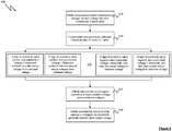
Figure 4 is a diagram illustrating steps in a method for selecting submodules of a valve of an MMC in order to achieve a desired valve output voltage; -
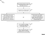
Figure 5 is a diagram illustrating steps in an alternative method for selecting submodules of a valve of an MMC in order to achieve a desired valve output voltage; -
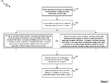
Figure 6 is a diagram illustrating steps in a further alternative method for selecting submodules of a valve of an MMC in order to achieve a desired valve output voltage; and -
Figure 7 is a diagram illustrating steps in a further alternative method for selecting submodules of a valve of an MMC in order to achieve a desired valve output voltage. - The present disclosure relates to an improved switching algorithm for a modular multilevel converter (MMC) which selectively activates the submodules of the valves of the MMC in order to generate a desired valve output voltage defined by a control valve voltage reference signal, whilst limiting commutation frequency losses in the MMC.
- Referring now to
Figure 4 , a method (algorithm) performed by theswitching algorithm function 295 for selecting submodules (either no submodules, one submodule, or more than one submodule) of a valve of anarm MMC 200 to be activated (inserted) in order to generate a desired valve output voltage is shown generally at 400. - In a
first step 410, a voltage value indicative of an instantaneous voltage across a storage element such as acapacitor 110 of each submodule of each valve ofarms energy storage element 110 at a sample time, using the first sensor of the valve. - A determination is then made for each submodule of each valve, at
step 420, as to whether that submodule was previously selected (i.e. selected at a preceding sample time). If the submodule was previously selected then a virtual voltage shift value, which in this example is a predetermined fixed value, is added to or subtracted from the obtained voltage value, depending upon the sign or polarity of instantaneous current flow (at the sample time) in the valve to which the submodule belongs, as explained below, to generate a modified voltage value. - If the submodule was previously selected, and the sign or polarity of instantaneous current flow at the sample time in the valve to which the submodule belongs (as measured, for example, by the second sensor of the valve) is negative, then the virtual shift voltage value is added to the obtained voltage value, such that the modified voltage value is greater than the obtained voltage value.
- If the submodule was previously selected, and the sign or polarity of instantaneous current flow at the sample time in the valve to which the submodule belongs (as measured, for example, by the second sensor of the valve) is positive, then the virtual shift voltage value is subtracted from the obtained voltage value, such that the modified voltage value is less than the obtained voltage value.
- If the submodule was not previously selected, then no virtual shift voltage value is added to or subtracted from the obtained voltage value.
- Once a modified voltage value has been generated for all of the submodules that were previously selected, all of the submodules of each valve are added to a histogram for that valve, at
step 430. The position of each submodule in its respective histogram is based on the modified voltage value (where a modified voltage value has been generated) or the obtained voltage value (where no modified voltage value has been generated). - At
step 440 the switching algorithm selects none, one or more submodules for each valve based on their rankings in the histogram (from lowest to highest or from highest to lowest) to be activated to generate a desired valve output voltage. The desired valve output voltage at each sample time is provided to the algorithm by thecontroller 290 as a reference voltage, and the switching algorithm selects none, one or more submodules for each valve at each sample time in order to create a voltage in the valve that is equal to the reference voltage provided by the controller. The submodules are selected in order from lowest to highest or highest to lowest, as a function of the sign of the current through the relevant arm(s). - Thus, for the valve of
arm 220T, none, one or more of the submodules 2241 - 224n are selected, based upon their rankings in the histogram for the valve ofarm 220T, to be activated such that the valve output voltage generated by the combination of the selected submodules is equal to the specified valve output voltage Vcontrol_ref_PhaseTopA. - Similarly, for the valve of
arm 220B, none, one or more of the submodules 2341 - 234n are selected, based upon their rankings in the histogram for the valve ofarm 220B, to be activated such that the valve output voltage generated by the combination of the selected submodules is equal to the specified valve output voltage Vcontrol_ref_PhaseBottomA. Adding the virtual voltage value to, or subtracting the virtual voltage value from, the obtained voltage value for submodules that were selected at the preceding sample time alters the position of those submodules in the histogram (as compared to positioning the submodules in the histogram based upon their obtained voltage values alone) and increases the likelihood that they will be selected again at the current sample time, which reduces the need to insert or bypass submodules by changing the state of their switching elements. Thus, the switching frequency of the submodules in the MMC is reduced, leading to a reduction in switching losses in the MMC. -
Figure 5 is a flow diagram illustrating steps in an alternative method 500 (algorithm) for selecting submodules (either no submodules, one submodule, or more than one submodule) of a valve of anarm MMC 200 to be activated in order to generate a desired valve output voltage. - In a
first step 510, a voltage value indicative of an instantaneous voltage across a storage element such as acapacitor 110 of each submodule of each valve ofarms energy storage element 110 at a sample time, using the first sensor of the valve. - A determination is then made for each submodule of each valve, at
step 520, as to whether that submodule was previously selected (i.e. selected at a preceding sample time). If the submodule was previously selected then the sign or polarity of instantaneous current flow (at the sample time) in the valve to which the submodule belongs (as measured, for example, by the second sensor of the valve) is determined. - At
step 530, one or more virtual voltage shift values are added to or subtracted from the obtained voltage value, depending on i) the sign or polarity of the instantaneous current flow (at the sample time) in the valve to which the submodule belongs and ii) the instantaneous voltage across the storage element of the submodule at the sample time. - Thus, if the sign or polarity of instantaneous current flow in the valve at the sample time is positive and the instantaneous voltage across the storage element at the sample time exceeds a predetermined threshold, only a first virtual voltage shift value is subtracted from the obtained submodule voltage to generate a modified voltage value. The first virtual voltage shift value may be a predetermined fixed value.
- However, if the sign or polarity of instantaneous current flow in the valve at the sample time is positive and the instantaneous voltage across the storage element at the sample time is below the predetermined threshold, the first virtual shift voltage value and a second virtual voltage shift value, which may be a predetermined fixed value that is equal to the first virtual voltage shift value, are subtracted from the obtained submodule voltage to generate a modified voltage value.
- If the sign or polarity of instantaneous current flow in the valve at the sample time is negative and the instantaneous voltage across the storage element at the sample time falls below a predetermined threshold, only a first virtual voltage shift value is added to the obtained submodule voltage to generate a modified voltage value. The first virtual voltage shift value may be a predetermined fixed value.
- If the sign or polarity of instantaneous current flow in the valve at the sample time is negative and the instantaneous voltage across the storage element at the sample time is below the predetermined threshold, the first virtual voltage shift value and a second virtual voltage shift value, which may be a predetermined fixed value that is equal to the first virtual voltage shift value, are added to the obtained submodule voltage to generate a modified voltage value.
- If the submodule was not previously selected, then no virtual voltage value is added to or subtracted from the obtained voltage value.
- Once a modified voltage value has been generated for all of the submodules that were previously selected, all of the submodules of each valve are added to a histogram for that valve, at
step 540. The position of each submodule in its respective histogram is based on the modified voltage value (where a modified voltage value has been generated) or the obtained voltage value (where no modified voltage value has been generated). - At
step 550 the switching algorithm selects none, one or more submodules for each valve based on their rankings in the histogram (from lowest to highest or from highest to lowest) to be activated to generate a desired valve output voltage. - Thus, for the valve of
arm 220T, none, one or more of the submodules 2241 - 224n are selected, based upon their rankings in the histogram for the valve ofarm 220T, to be activated such that the valve output voltage generated by the combination of the selected submodules is equal to the specified valve output voltage Vcontrol_ref_PhaseTopA. - Similarly, for the valve of
arm 220B, none, one or more of the submodules 2341 - 234n are selected, based upon their rankings in the histogram for the valve ofarm 220B, to be activated such that the valve output voltage generated by the combination of the selected submodules is equal to the specified valve output voltage Vcontrol_ref_PhaseBottomA. - As in the method discussed above in relation to
Figure 4 , adding the first virtual shift voltage value to, or subtracting the first virtual shift voltage value from, the obtained voltage value for submodules that were selected at the preceding sample time alters the position of those submodules in the histogram (as compared to positioning the submodules in the histogram based upon their obtained voltage values alone) and increases the likelihood that they will be selected again at the current sample time, which reduces the need to insert or bypass submodules by changing the state of their switching elements. Thus, the switching frequency of the submodules in the MMC is reduced, leading to a reduction in switching losses in the MMC. - Additionally, adding the second virtual voltage shift value to, or subtracting the second virtual voltage shift value from, the obtained voltage value increases the voltage band of the submodules, thereby further reducing the need for submodules to be inserted or bypassed in the MMC and thus further reducing the average commutation frequency of the submodules and associated switching losses in the MMC.
- Referring now to
Figure 6 , a further alternative method (algorithm) for selecting submodules (either no submodules, one submodule, or more than one submodule) of a valve of anarm MMC 200 to be activated in order to generate a desired valve output voltage, is shown generally at 600. - In a
first step 610, a voltage value indicative of an instantaneous voltage across a storage element such as acapacitor 110 of each submodule of each valve ofarms energy storage element 110 at a sample time, using the first sensor of the valve. - A determination is then made for each submodule of each valve, at
step 620, as to whether that submodule was previously selected (i.e. selected at a preceding sample time). If the submodule was previously selected then the sign or polarity of instantaneous current flow (at the sample time) in the valve to which the submodule belongs (as measured, for example, by the second sensor of the valve) is determined. - At
step 630, a dynamic voltage shift value is generated based on i) the polarity or sign of instantaneous current flow in the valve to which the submodule belongs and ii) a threshold representing either a minimum or a maximum voltage across thestorage element 110 of the submodule, depending upon the sign or polarity of instantaneous current flow in the valve. - Thus, if the sign or polarity of instantaneous current flow in the valve at the sample time is positive, the instantaneous voltage across the
storage element 110 of the submodule at the sample time is compared to a maximum voltage threshold representing a maximum voltage value across thestorage element 110 of the submodule. A dynamic voltage shift value is obtained by calculating the difference between the maximum voltage threshold and the instantaneous voltage across thestorage element 110 of the submodule at the sample time. If this dynamic voltage shift value is below a predefined maximum voltage shift value and above a predefined minimum voltage shift value, then the dynamic voltage shift value is subtracted from the obtained voltage value for the submodule to generate a modified voltage value for the submodule. If the dynamic shift value is below the predefined minimum voltage shift value, then the predefined minimum voltage shift value is subtracted from the obtained voltage value to generate the modified voltage value for the submodule. If the dynamic shift value meets or exceeds the predefined maximum voltage shift value, then the predefined maximum voltage shift value is subtracted from the obtained voltage value to generate the modified voltage value for the submodule. - If the sign or polarity of instantaneous current flow in the valve at the sample time is negative, the instantaneous voltage across the
storage element 110 of the submodule at the sample time is compared to a minimum voltage threshold representing a minimum voltage value across thestorage element 110 of the submodule. A dynamic voltage shift value is obtained by calculating the difference between the instantaneous voltage across the submodule at the sample time and the minimum voltage threshold. If this dynamic voltage shift value is below the predefined maximum voltage shift value and above the predefined minimum voltage shift value, then the dynamic voltage shift value is added to the obtained voltage value for the submodule to generate a modified voltage value for the submodule. If the dynamic shift value is below the predefined minimum voltage shift value, then the predefined minimum voltage shift value is added to the obtained voltage value to generate the modified voltage value for the submodule. If the dynamic shift value meets or exceeds the predefined maximum voltage shift value, then the predefined maximum voltage shift value is added to the obtained voltage value to generate the modified voltage value for the submodule. - Once a modified voltage value has been generated for all of the submodules that were previously selected, all of the submodules of each valve are added to a histogram for that valve, at
step 640. The position of each submodule in its respective histogram is based on the modified voltage value (where a modified voltage value has been generated) or the obtained voltage value (where no modified voltage value has been generated). - At
step 650 the switching algorithm selects none, one or more submodules for each valve based on their rankings in the histogram (from lowest to highest or from highest to lowest) to be activated to generate a desired valve output voltage. - Thus, for the valve of
arm 220T, none, one or more of the submodules 2241 - 224n are selected, based upon their rankings in the histogram for the valve ofarm 220T, to be activated such that the valve output voltage generated by the combination of the selected submodules is equal to the specified valve output voltage Vcontrol_ref_PhaseTopA. - Similarly, for the valve of
arm 220B, none, one or more of the submodules 2341 - 234n are selected, based upon their rankings in the histogram forvalve 220B, to be activated such that the valve output voltage generated by the combination of the selected submodules is equal to the specified valve output voltage Vcontrol_ref_PhaseBottomA. - As in the previous examples, adding the shift voltage value to, or subtracting the shift voltage value from, the obtained voltage value for submodules that were selected at the preceding sample time alters the position of those submodules in the histogram (as compared to positioning the submodules in the histogram based upon their obtained voltage values alone) and increases the likelihood that they will be selected again at the current sample time, which reduces the need to insert or bypass submodules by changing the state of their switching elements. Thus, the switching frequency of the submodules in the MMC is reduced, leading to a reduction in switching losses in the MMC. Further, the use of upper and lower value thresholds imposes a limit on the commutation frequency of the submodules, thereby limiting switching losses.
- Referring now to
Figure 7 , a further alternative method (algorithm), for selecting submodules (either no submodules, one submodule, or more than one submodule) of a valve of anarm MMC 200 to be activated in order to generate a desired valve output voltage, is shown generally at 700. Themethod 700 combines features of themethods Figures 5 and6 . - In a
first step 710, a voltage value indicative of an instantaneous voltage across a storage element such as acapacitor 110 of each submodule of each valve ofarms energy storage element 110 at a sample time, using the first sensor of the valve. - A determination is then made for each submodule of each valve, at
step 720, as to whether that submodule was previously selected (i.e. selected at a preceding sample time). If the submodule was previously selected then the sign or polarity of instantaneous current flow (at the sample time) in the valve to which the submodule belongs (as measured, for example, by the second sensor of the valve) is determined. - At
step 730, a dynamic voltage shift value is generated based on i) the polarity or sign of instantaneous current flow in the valve to which the submodule belongs and ii) a threshold representing the minimum or maximum voltage across thestorage element 110 of the submodule. - Thus, if the sign or polarity of instantaneous current flow in the valve at the sample time is positive, the instantaneous voltage across the
storage element 110 of the submodule at the sample time is compared to a maximum voltage threshold representing a maximum voltage value across thestorage element 110 of the submodule. A dynamic voltage shift value is obtained by calculating the difference between the maximum voltage threshold and the instantaneous voltage across thestorage element 110 of the submodule at the sample time. The dynamic voltage shift value may be multiplied by a gain value to obtain a modified voltage shift value. - If the (modified) dynamic voltage shift value is below a predefined maximum voltage shift value and above a predefined minimum voltage shift value, then the modified dynamic voltage shift value is retained as a voltage shift value for subsequent use. If the modified dynamic shift value is below a predefined minimum voltage shift value, then the predefined minimum voltage shift value is retained as the voltage shift value for subsequent use. If the modified dynamic shift value meets or exceeds the predefined maximum voltage shift value, then the predefined maximum voltage shift value is retained as the voltage shift value for subsequent use.
- The instantaneous voltage across the
storage element 110 at the sample time is then compared to a first threshold. If the instantaneous voltage across thestorage element 110 at the sample time is less than the first threshold, then the voltage shift value is multiplied by a first gain value, and the result of this multiplication is subtracted from the obtained voltage value to generate a modified voltage value for the submodule. If the instantaneous voltage across thestorage element 110 at the sample time is greater than the first threshold, then the voltage shift value is multiplied by a second gain value, which may be a multiple of the first value, and the result of this multiplication is subtracted from the obtained voltage value to generate the modified voltage value for the submodule. - If the sign or polarity of instantaneous current flow in the valve at the sample time is negative, the instantaneous voltage across the
storage element 110 of the submodule at the sample time is compared to a minimum voltage threshold representing a minimum voltage value across thestorage element 110 of the submodule. A dynamic voltage shift value is obtained by calculating the difference between the instantaneous voltage across thestorage element 110 of the submodule at the sample time and the minimum voltage threshold and. The dynamic voltage shift value may be multiplied a gain value to obtain a modified voltage shift value. - If the (modified) dynamic voltage shift value is below a predefined maximum voltage shift value and above a predefined minimum voltage shift value, then the modified dynamic voltage shift value is retained as a voltage shift value for subsequent use. If the modified dynamic shift value is below a predefined minimum voltage shift value, then the predefined minimum voltage shift value is retained as the voltage shift value for subsequent use. If the modified dynamic shift value meets or exceeds the predefined maximum voltage shift value, then the predefined maximum voltage shift value is retained as the voltage shift value for subsequent use.
- The instantaneous voltage across the
storage element 110 at the sample time is then compared to a second threshold. If the instantaneous voltage across thestorage element 110 at the sample time is greater than the second threshold, then the voltage shift value is multiplied by a third gain value, and the result of this multiplication is added to the obtained voltage value to generate a modified voltage value for the submodule. If the instantaneous voltage across thestorage element 110 at the sample time is less than the second threshold, then the voltage shift value is multiplied by a fourth gain value, which may be a multiple of the third gain value, and the result of this multiplication is added to the obtained voltage value to generate the modified voltage value for the submodule. - Once a modified voltage value has been generated for all of the submodules that were previously selected, all of the submodules of each valve are added to a histogram for that valve, at
step 740. The position of each submodule in its respective histogram is based on the modified voltage value (where a modified voltage value has been generated) or the obtained voltage value (where no modified voltage value has been generated). - At
step 750 the switching algorithm selects none, one or more submodules for each valve based on their rankings in the histogram (from lowest to highest or from highest to lowest) to be activated to generate a desired valve output voltage. - Thus, for the valve of
arm 220T, none, one or more of the submodules 2241 - 224n are selected, based upon their rankings in the histogram for the valve ofarm 220T, to be activated such that the valve output voltage generated by the combination of the selected submodules is equal to the specified valve output voltage Vcontrol_ref_PhaseTopA. - Similarly, for the valve of
arm 220B, none, one or more of the submodules 2341 - 234n are selected, based upon their rankings in the histogram forvalve 220B, to be activated such that the valve output voltage generated by the combination of the selected submodules is equal to the specified valve output voltage Vcontrol_ref_PhaseBottomA. - As in the previous examples, adding the shift voltage value to, or subtracting the shift virtual voltage value from, the obtained voltage value for submodules that were selected at the preceding sample time alters the position of those submodules in the histogram (as compared to positioning the submodules in the histogram based upon their obtained voltage values alone) and increases the likelihood that they will be selected again at the current sample time, which reduces the need to switch submodules in and out and thus reduces the average commutation frequency of the submodules and therefore reduces switching losses in the MMC.
- As will be appreciated from the foregoing, the methods described above reduce switching losses arising in a MMC due to insertion and bypassing of submodules, as the likelihood that a submodule that was previously selected will be selected again, thus reducing the need to insert and bypass submodules by adjusting the state of their switching elements. Thus, the average commutation frequency of the submodules of the MMC can be reduced, reducing losses.
- The switching algorithm and the
switching algorithm function 295 may be implemented in hardware, or may be implemented in one or more processing units, e.g. computers, executing instructions to perform the methods described above. The instructions may be stored on any convenient computer readable storage medium such as static or dynamic memory, hard disc, CD-ROM, DVD-ROM or the like. - It should be noted that the above-mentioned embodiments illustrate rather than limit the invention, and that those skilled in the art will be able to design many alternative embodiments without departing from the scope of the appended claims. The word "comprising" does not exclude the presence of elements or steps other than those listed in a claim, "a" or "an" does not exclude a plurality. Any reference signs in the claims shall not be construed so as to limit their scope.
Claims (15)
- A method for selecting submodules of a valve of modular multilevel converter in order to generate a desired valve output voltage, the method comprising:obtaining a voltage value for each submodule of the valve indicative of a voltage across an energy storage element of the submodule;for each submodule of the valve:if the submodule was previously selected:adding or subtracting a first shift voltage value to the obtained voltage value for the submodule based on a sign of a current in the valve to generate a modified voltage value for the submodule; andadding the submodule to a histogram according to the modified voltage value for the submodule;if the submodule was not previously selected:and
adding the submodule to a histogram according to the voltage value for the submodule;selecting no submodules, one submodule or more than one submodule, based on their ranking in the histogram, to activate so as to generate the desired valve output voltage. - A method according to claim 1 wherein the first shift voltage value is a predefined fixed value.
- A method according to claim 1 or claim 2 wherein, if the sign of the current in the valve is negative, the first shift voltage value is added to the obtained voltage value, and wherein, if the sign of the current in the valve is positive, the first shift voltage value is subtracted from the obtained voltage value.
- A method according to claim 3 further comprising:if the sign of the current in the valve is negative and a voltage across the energy storage element of the submodule exceeds a predetermined threshold, adding a second shift voltage value to the obtained voltage value, as well as adding the first shift voltage value to the obtained voltage value, to generate the modified voltage value for the submodule; andif the sign of the current in the valve is positive and the voltage across the energy storage element of the submodule is less than a predetermined threshold, subtracting a second shift voltage value from the obtained voltage value, as well as subtracting the first shift voltage value from the obtained voltage value, to generate the modified voltage value for the submodule.
- A method according to claim 1, wherein the first shift voltage value is a dynamic value that is calculated by comparing the voltage value for the submodule to a minimum or a maximum value threshold, based on the sign of a current in the valve.
- A method according to claim 5 wherein:if the sign of the current in the valve is negative, the first shift voltage value is calculated by comparing the voltage value for the submodule to a minimum value threshold, and the first shift voltage value is added to the obtained voltage value to generate the modified voltage value for the submodule; andif the sign of the current in the valve is positive, the first shift voltage value is calculated by comparing the voltage value for the submodule to a maximum value threshold, and the first shift voltage value is subtracted from the obtained voltage value to generate the modified voltage value for the submodule.
- A method according to claim 6 wherein:if the sign of the current in the valve is negative and the first shift voltage value is below the minimum value threshold, the value of the minimum value threshold is added to the obtained voltage value to generate the modified voltage value for the submodule;if the sign of the current in the valve is negative and the first shift voltage value exceeds the maximum value threshold, the value of the maximum value threshold is added to the obtained voltage value to generate the modified voltage value for the submodule;if the sign of the current in the valve is positive and the first shift voltage value is below the minimum value threshold, the value of the minimum value threshold is subtracted from the obtained voltage value to generate the modified voltage value for the submodule; andif the sign of the current in the valve is positive and the first shift voltage value exceeds the maximum value threshold, the value of the maximum value threshold is subtracted from the obtained voltage value to generate the modified voltage value for the submodule.
- A method according to claim 6 further comprising:if the sign of the current in the valve is positive, comparing the obtained voltage value to a first threshold and:if the obtained voltage value is less than the first threshold, multiplying the first shift voltage value by a first gain value and subtracting the result of the multiplication from the obtained voltage value to generate the modified voltage value;if the obtained voltage value is greater than the first threshold, multiplying the first shift voltage value by a second gain value and subtracting the result of the multiplication from the obtained voltage value to generate the modified voltage value; andif the sign of the current in the valve is negative, comparing the obtained voltage value to a second threshold and:if the obtained voltage value is greater than the second threshold, multiplying the first shift voltage value by a third gain value and adding the result of the multiplication to the obtained voltage value to generate the modified voltage value; andif the obtained voltage value is less than the second threshold, multiplying the first shift voltage value by a fourth gain value and adding the result of the multiplication to the obtained voltage value to generate the modified voltage value.
- A method according to claim 8, further comprising:if the sign of the current in the valve is positive, prior to comparing the obtained voltage value to the first threshold, multiplying the first shift voltage value by a gain value to obtain a modified voltage shift value; andif the sign of the current in the valve is negative, prior to comparing the obtained voltage value to a second threshold, multiplying the first shift voltage value by the gain value to obtain a modified voltage shift value.
- A method according to claim 8 or claim 9 wherein:if the sign of the current in the valve is positive and the first shift voltage value is below a minimum value threshold, retaining the value of the minimum value threshold for subsequent use as the first shift voltage value;if the sign of the current in the valve is positive and the first shift voltage value exceeds a maximum value threshold, retaining the value of the maximum value threshold for subsequent use as the first shift voltage value;if the sign of the current in the valve is negative and the first shift voltage value is below the minimum value threshold, retaining the value of the minimum value threshold for subsequent use as the first shift voltage value; andif the sign of the current in the valve is negative and the first shift voltage value exceeds the maximum value threshold, retaining the value of the maximum value threshold for subsequent use as the first shift voltage value.
- A computer program comprising instructions which, when executed by a processing unit, causes the processing unit to perform the method of any one of the preceding claims.
- A processing system comprising one or more processing units configured to execute the computer program of claim 11.
- A modular multilevel converter comprising:a plurality of valves, wherein each valve comprises:a plurality of submodules;a first sensor configured to indicate a voltage value for each submodule of the valve;a second sensor configured to indicate a polarity or sign of a current in the valve;anda control unit configured to select submodules of the valve of the modular multilevel converter in order to generate a desired valve output voltage,characterised in that said control unit is configured, upon receipt of indications from said first sensor and said second sensor, to:for each submodule of the valve:if the submodule was previously selected:add or subtract a first shift voltage value to the obtained voltage value for the submodule based on the sign of a current in the valve to generate a modified voltage value for the submodule; andadd the submodule to a histogram according to the modified voltage value for the submodule;if the submodule was not previously selected:and
add the submodule to a histogram according to the voltage value for the submodule;select no submodules, one submodule or more than one submodule, based on their ranking in the histogram, to activate so as to generate the desired valve output voltage. - A modular multilevel converter according to claim 13 wherein each valve further comprises a limb reactor.
- A modular multilevel converter according to claim 14 wherein the limb reactor comprises an inductance or a series combination of an inductance and a resistance.
Priority Applications (4)
| Application Number | Priority Date | Filing Date | Title |
|---|---|---|---|
| ES19170425T ES2940435T3 (en) | 2019-04-19 | 2019-04-19 | Selection of the MMC submodule |
| DK19170425.3T DK3726721T3 (en) | 2019-04-19 | 2019-04-19 | SELECTION OF MMC SUBMODULE |
| EP19170425.3A EP3726721B1 (en) | 2019-04-19 | 2019-04-19 | Mmc submodule selection |
| PCT/EP2020/057131 WO2020212046A1 (en) | 2019-04-19 | 2020-03-16 | Mmc submodule selection |
Applications Claiming Priority (1)
| Application Number | Priority Date | Filing Date | Title |
|---|---|---|---|
| EP19170425.3A EP3726721B1 (en) | 2019-04-19 | 2019-04-19 | Mmc submodule selection |
Publications (2)
| Publication Number | Publication Date |
|---|---|
| EP3726721A1 true EP3726721A1 (en) | 2020-10-21 |
| EP3726721B1 EP3726721B1 (en) | 2023-01-25 |
Family
ID=66239994
Family Applications (1)
| Application Number | Title | Priority Date | Filing Date |
|---|---|---|---|
| EP19170425.3A Active EP3726721B1 (en) | 2019-04-19 | 2019-04-19 | Mmc submodule selection |
Country Status (4)
| Country | Link |
|---|---|
| EP (1) | EP3726721B1 (en) |
| DK (1) | DK3726721T3 (en) |
| ES (1) | ES2940435T3 (en) |
| WO (1) | WO2020212046A1 (en) |
-
2019
- 2019-04-19 EP EP19170425.3A patent/EP3726721B1/en active Active
- 2019-04-19 DK DK19170425.3T patent/DK3726721T3/en active
- 2019-04-19 ES ES19170425T patent/ES2940435T3/en active Active
-
2020
- 2020-03-16 WO PCT/EP2020/057131 patent/WO2020212046A1/en not_active Ceased
Non-Patent Citations (3)
| Title |
|---|
| ANTONIO-FERREIRA ABEL ET AL: "Comparison of cell selection methods for modular multilevel converters", 2016 IEEE 16TH INTERNATIONAL CONFERENCE ON ENVIRONMENT AND ELECTRICAL ENGINEERING (EEEIC), IEEE, 7 June 2016 (2016-06-07), pages 1 - 8, XP032954785, DOI: 10.1109/EEEIC.2016.7555608 * |
| DARUS ROSHEILA ET AL: "A Modified Voltage Balancing Algorithm for the Modular Multilevel Converter: Evaluation for Staircase and Phase-Disposition PWM", IEEE TRANSACTIONS ON POWER ELECTRONICS, INSTITUTE OF ELECTRICAL AND ELECTRONICS ENGINEERS, USA, vol. 30, no. 8, 1 August 2015 (2015-08-01), pages 4119 - 4127, XP011574692, ISSN: 0885-8993, [retrieved on 20150305], DOI: 10.1109/TPEL.2014.2359005 * |
| QIN JIANGCHAO ET AL: "Reduced Switching-Frequency Voltage-Balancing Strategies for Modular Multilevel HVDC Converters", IEEE TRANSACTIONS ON POWER DELIVERY, IEEE SERVICE CENTER, NEW YORK, NY, US, vol. 28, no. 4, 1 October 2013 (2013-10-01), pages 2403 - 2410, XP011528420, ISSN: 0885-8977, [retrieved on 20130930], DOI: 10.1109/TPWRD.2013.2271615 * |
Also Published As
| Publication number | Publication date |
|---|---|
| ES2940435T3 (en) | 2023-05-08 |
| WO2020212046A1 (en) | 2020-10-22 |
| EP3726721B1 (en) | 2023-01-25 |
| DK3726721T3 (en) | 2023-03-20 |
Similar Documents
| Publication | Publication Date | Title |
|---|---|---|
| EP3148067B1 (en) | Direct-current power transmission power conversion device and direct-current power transmission power conversion method | |
| JP6676229B1 (en) | Power converter | |
| JP6448882B1 (en) | Power converter | |
| US9966777B2 (en) | Modular multilevel converter for hybrid energy storage | |
| US12273045B2 (en) | Power conversion device with individual cell and arm balancing | |
| AU2013227754B2 (en) | Indirect matrix converter | |
| US20150200602A1 (en) | Multilevel converter systems and methods with reduced common mode voltage | |
| US12413156B2 (en) | Capacitor balancing control in an HVDC MMC | |
| JP7476585B2 (en) | Power Conversion Equipment | |
| EP3375082B1 (en) | A modular multilevel converter for handling ac side faults | |
| US20220393616A1 (en) | Power conversion device | |
| US20180091058A1 (en) | Multiphase multilevel power converter, control apparatus and methods to control harmonics during bypass operation | |
| JP6926355B1 (en) | Power converter | |
| EP3726721B1 (en) | Mmc submodule selection | |
| KR20230098137A (en) | Systems and methods for soft-switching current source converter control | |
| US20240258931A1 (en) | Fault tolerance control of solid state transformer | |
| US12525805B2 (en) | Power control system | |
| US11575329B1 (en) | Balanced current-source inverter | |
| JP7134312B2 (en) | power converter | |
| JP6873352B1 (en) | Power conversion system and its control device | |
| CN112534695B (en) | Methods for controlling MMC | |
| Oh et al. | Open-Circuit Fault Diagnosis in Single-Phase Cascaded H-bridge Multilevel Converter with Switching Duty Ratio-Based Estimated Grid Current | |
| JP7418675B1 (en) | power converter | |
| WO2022213185A1 (en) | Multi-level voltage sourced converter submodule with parallel current-conducting branches with multiple energy storage devices and related methods | |
| EP4572067A1 (en) | Power conversion system and control device |
Legal Events
| Date | Code | Title | Description |
|---|---|---|---|
| PUAI | Public reference made under article 153(3) epc to a published international application that has entered the european phase |
Free format text: ORIGINAL CODE: 0009012 |
|
| STAA | Information on the status of an ep patent application or granted ep patent |
Free format text: STATUS: THE APPLICATION HAS BEEN PUBLISHED |
|
| AK | Designated contracting states |
Kind code of ref document: A1 Designated state(s): AL AT BE BG CH CY CZ DE DK EE ES FI FR GB GR HR HU IE IS IT LI LT LU LV MC MK MT NL NO PL PT RO RS SE SI SK SM TR |
|
| AX | Request for extension of the european patent |
Extension state: BA ME |
|
| STAA | Information on the status of an ep patent application or granted ep patent |
Free format text: STATUS: REQUEST FOR EXAMINATION WAS MADE |
|
| 17P | Request for examination filed |
Effective date: 20210414 |
|
| RBV | Designated contracting states (corrected) |
Designated state(s): AL AT BE BG CH CY CZ DE DK EE ES FI FR GB GR HR HU IE IS IT LI LT LU LV MC MK MT NL NO PL PT RO RS SE SI SK SM TR |
|
| STAA | Information on the status of an ep patent application or granted ep patent |
Free format text: STATUS: EXAMINATION IS IN PROGRESS |
|
| 17Q | First examination report despatched |
Effective date: 20210526 |
|
| GRAP | Despatch of communication of intention to grant a patent |
Free format text: ORIGINAL CODE: EPIDOSNIGR1 |
|
| STAA | Information on the status of an ep patent application or granted ep patent |
Free format text: STATUS: GRANT OF PATENT IS INTENDED |
|
| INTG | Intention to grant announced |
Effective date: 20220906 |
|
| GRAS | Grant fee paid |
Free format text: ORIGINAL CODE: EPIDOSNIGR3 |
|
| GRAA | (expected) grant |
Free format text: ORIGINAL CODE: 0009210 |
|
| STAA | Information on the status of an ep patent application or granted ep patent |
Free format text: STATUS: THE PATENT HAS BEEN GRANTED |
|
| AK | Designated contracting states |
Kind code of ref document: B1 Designated state(s): AL AT BE BG CH CY CZ DE DK EE ES FI FR GB GR HR HU IE IS IT LI LT LU LV MC MK MT NL NO PL PT RO RS SE SI SK SM TR |
|
| REG | Reference to a national code |
Ref country code: GB Ref legal event code: FG4D |
|
| REG | Reference to a national code |
Ref country code: CH Ref legal event code: EP |
|
| REG | Reference to a national code |
Ref country code: AT Ref legal event code: REF Ref document number: 1546506 Country of ref document: AT Kind code of ref document: T Effective date: 20230215 Ref country code: IE Ref legal event code: FG4D |
|
| REG | Reference to a national code |
Ref country code: DE Ref legal event code: R096 Ref document number: 602019024693 Country of ref document: DE |
|
| REG | Reference to a national code |
Ref country code: DK Ref legal event code: T3 Effective date: 20230314 |
|
| REG | Reference to a national code |
Ref country code: NL Ref legal event code: FP |
|
| REG | Reference to a national code |
Ref country code: SE Ref legal event code: TRGR |
|
| REG | Reference to a national code |
Ref country code: ES Ref legal event code: FG2A Ref document number: 2940435 Country of ref document: ES Kind code of ref document: T3 Effective date: 20230508 |
|
| REG | Reference to a national code |
Ref country code: LT Ref legal event code: MG9D |
|
| REG | Reference to a national code |
Ref country code: AT Ref legal event code: MK05 Ref document number: 1546506 Country of ref document: AT Kind code of ref document: T Effective date: 20230125 |
|
| P01 | Opt-out of the competence of the unified patent court (upc) registered |
Effective date: 20230522 |
|
| PG25 | Lapsed in a contracting state [announced via postgrant information from national office to epo] |
Ref country code: RS Free format text: LAPSE BECAUSE OF FAILURE TO SUBMIT A TRANSLATION OF THE DESCRIPTION OR TO PAY THE FEE WITHIN THE PRESCRIBED TIME-LIMIT Effective date: 20230125 Ref country code: PT Free format text: LAPSE BECAUSE OF FAILURE TO SUBMIT A TRANSLATION OF THE DESCRIPTION OR TO PAY THE FEE WITHIN THE PRESCRIBED TIME-LIMIT Effective date: 20230525 Ref country code: NO Free format text: LAPSE BECAUSE OF FAILURE TO SUBMIT A TRANSLATION OF THE DESCRIPTION OR TO PAY THE FEE WITHIN THE PRESCRIBED TIME-LIMIT Effective date: 20230425 Ref country code: LV Free format text: LAPSE BECAUSE OF FAILURE TO SUBMIT A TRANSLATION OF THE DESCRIPTION OR TO PAY THE FEE WITHIN THE PRESCRIBED TIME-LIMIT Effective date: 20230125 Ref country code: LT Free format text: LAPSE BECAUSE OF FAILURE TO SUBMIT A TRANSLATION OF THE DESCRIPTION OR TO PAY THE FEE WITHIN THE PRESCRIBED TIME-LIMIT Effective date: 20230125 Ref country code: HR Free format text: LAPSE BECAUSE OF FAILURE TO SUBMIT A TRANSLATION OF THE DESCRIPTION OR TO PAY THE FEE WITHIN THE PRESCRIBED TIME-LIMIT Effective date: 20230125 Ref country code: AT Free format text: LAPSE BECAUSE OF FAILURE TO SUBMIT A TRANSLATION OF THE DESCRIPTION OR TO PAY THE FEE WITHIN THE PRESCRIBED TIME-LIMIT Effective date: 20230125 |
|
| PG25 | Lapsed in a contracting state [announced via postgrant information from national office to epo] |
Ref country code: PL Free format text: LAPSE BECAUSE OF FAILURE TO SUBMIT A TRANSLATION OF THE DESCRIPTION OR TO PAY THE FEE WITHIN THE PRESCRIBED TIME-LIMIT Effective date: 20230125 Ref country code: IS Free format text: LAPSE BECAUSE OF FAILURE TO SUBMIT A TRANSLATION OF THE DESCRIPTION OR TO PAY THE FEE WITHIN THE PRESCRIBED TIME-LIMIT Effective date: 20230525 Ref country code: GR Free format text: LAPSE BECAUSE OF FAILURE TO SUBMIT A TRANSLATION OF THE DESCRIPTION OR TO PAY THE FEE WITHIN THE PRESCRIBED TIME-LIMIT Effective date: 20230426 Ref country code: FI Free format text: LAPSE BECAUSE OF FAILURE TO SUBMIT A TRANSLATION OF THE DESCRIPTION OR TO PAY THE FEE WITHIN THE PRESCRIBED TIME-LIMIT Effective date: 20230125 |
|
| REG | Reference to a national code |
Ref country code: DE Ref legal event code: R097 Ref document number: 602019024693 Country of ref document: DE |
|
| PG25 | Lapsed in a contracting state [announced via postgrant information from national office to epo] |
Ref country code: SM Free format text: LAPSE BECAUSE OF FAILURE TO SUBMIT A TRANSLATION OF THE DESCRIPTION OR TO PAY THE FEE WITHIN THE PRESCRIBED TIME-LIMIT Effective date: 20230125 Ref country code: RO Free format text: LAPSE BECAUSE OF FAILURE TO SUBMIT A TRANSLATION OF THE DESCRIPTION OR TO PAY THE FEE WITHIN THE PRESCRIBED TIME-LIMIT Effective date: 20230125 Ref country code: EE Free format text: LAPSE BECAUSE OF FAILURE TO SUBMIT A TRANSLATION OF THE DESCRIPTION OR TO PAY THE FEE WITHIN THE PRESCRIBED TIME-LIMIT Effective date: 20230125 Ref country code: CZ Free format text: LAPSE BECAUSE OF FAILURE TO SUBMIT A TRANSLATION OF THE DESCRIPTION OR TO PAY THE FEE WITHIN THE PRESCRIBED TIME-LIMIT Effective date: 20230125 |
|
| PG25 | Lapsed in a contracting state [announced via postgrant information from national office to epo] |
Ref country code: SK Free format text: LAPSE BECAUSE OF FAILURE TO SUBMIT A TRANSLATION OF THE DESCRIPTION OR TO PAY THE FEE WITHIN THE PRESCRIBED TIME-LIMIT Effective date: 20230125 |
|
| REG | Reference to a national code |
Ref country code: CH Ref legal event code: PL |
|
| PLBE | No opposition filed within time limit |
Free format text: ORIGINAL CODE: 0009261 |
|
| STAA | Information on the status of an ep patent application or granted ep patent |
Free format text: STATUS: NO OPPOSITION FILED WITHIN TIME LIMIT |
|
| PG25 | Lapsed in a contracting state [announced via postgrant information from national office to epo] |
Ref country code: LU Free format text: LAPSE BECAUSE OF NON-PAYMENT OF DUE FEES Effective date: 20230419 |
|
| 26N | No opposition filed |
Effective date: 20231026 |
|
| PG25 | Lapsed in a contracting state [announced via postgrant information from national office to epo] |
Ref country code: MC Free format text: LAPSE BECAUSE OF FAILURE TO SUBMIT A TRANSLATION OF THE DESCRIPTION OR TO PAY THE FEE WITHIN THE PRESCRIBED TIME-LIMIT Effective date: 20230125 |
|
| PG25 | Lapsed in a contracting state [announced via postgrant information from national office to epo] |
Ref country code: SI Free format text: LAPSE BECAUSE OF FAILURE TO SUBMIT A TRANSLATION OF THE DESCRIPTION OR TO PAY THE FEE WITHIN THE PRESCRIBED TIME-LIMIT Effective date: 20230125 Ref country code: MC Free format text: LAPSE BECAUSE OF FAILURE TO SUBMIT A TRANSLATION OF THE DESCRIPTION OR TO PAY THE FEE WITHIN THE PRESCRIBED TIME-LIMIT Effective date: 20230125 Ref country code: LI Free format text: LAPSE BECAUSE OF NON-PAYMENT OF DUE FEES Effective date: 20230430 Ref country code: CH Free format text: LAPSE BECAUSE OF NON-PAYMENT OF DUE FEES Effective date: 20230430 |
|
| REG | Reference to a national code |
Ref country code: IE Ref legal event code: MM4A |
|
| PG25 | Lapsed in a contracting state [announced via postgrant information from national office to epo] |
Ref country code: IE Free format text: LAPSE BECAUSE OF NON-PAYMENT OF DUE FEES Effective date: 20230419 |
|
| PG25 | Lapsed in a contracting state [announced via postgrant information from national office to epo] |
Ref country code: IE Free format text: LAPSE BECAUSE OF NON-PAYMENT OF DUE FEES Effective date: 20230419 |
|
| PG25 | Lapsed in a contracting state [announced via postgrant information from national office to epo] |
Ref country code: BG Free format text: LAPSE BECAUSE OF FAILURE TO SUBMIT A TRANSLATION OF THE DESCRIPTION OR TO PAY THE FEE WITHIN THE PRESCRIBED TIME-LIMIT Effective date: 20230125 |
|
| PG25 | Lapsed in a contracting state [announced via postgrant information from national office to epo] |
Ref country code: BG Free format text: LAPSE BECAUSE OF FAILURE TO SUBMIT A TRANSLATION OF THE DESCRIPTION OR TO PAY THE FEE WITHIN THE PRESCRIBED TIME-LIMIT Effective date: 20230125 |
|
| PGFP | Annual fee paid to national office [announced via postgrant information from national office to epo] |
Ref country code: DE Payment date: 20250319 Year of fee payment: 7 |
|
| PGFP | Annual fee paid to national office [announced via postgrant information from national office to epo] |
Ref country code: ES Payment date: 20250502 Year of fee payment: 7 |
|
| PG25 | Lapsed in a contracting state [announced via postgrant information from national office to epo] |
Ref country code: CY Free format text: LAPSE BECAUSE OF FAILURE TO SUBMIT A TRANSLATION OF THE DESCRIPTION OR TO PAY THE FEE WITHIN THE PRESCRIBED TIME-LIMIT; INVALID AB INITIO Effective date: 20190419 |
|
| PG25 | Lapsed in a contracting state [announced via postgrant information from national office to epo] |
Ref country code: HU Free format text: LAPSE BECAUSE OF FAILURE TO SUBMIT A TRANSLATION OF THE DESCRIPTION OR TO PAY THE FEE WITHIN THE PRESCRIBED TIME-LIMIT; INVALID AB INITIO Effective date: 20190419 |
|
| PG25 | Lapsed in a contracting state [announced via postgrant information from national office to epo] |
Ref country code: TR Free format text: LAPSE BECAUSE OF FAILURE TO SUBMIT A TRANSLATION OF THE DESCRIPTION OR TO PAY THE FEE WITHIN THE PRESCRIBED TIME-LIMIT Effective date: 20230125 |
|
| PGFP | Annual fee paid to national office [announced via postgrant information from national office to epo] |
Ref country code: SE Payment date: 20260319 Year of fee payment: 8 |
|
| PGFP | Annual fee paid to national office [announced via postgrant information from national office to epo] |
Ref country code: GB Payment date: 20260319 Year of fee payment: 8 |
|
| PGFP | Annual fee paid to national office [announced via postgrant information from national office to epo] |
Ref country code: DK Payment date: 20260319 Year of fee payment: 8 |
|
| PGFP | Annual fee paid to national office [announced via postgrant information from national office to epo] |
Ref country code: BE Payment date: 20260319 Year of fee payment: 8 Ref country code: IT Payment date: 20260319 Year of fee payment: 8 |
|
| PGFP | Annual fee paid to national office [announced via postgrant information from national office to epo] |
Ref country code: NL Payment date: 20260319 Year of fee payment: 8 |
|
| PGFP | Annual fee paid to national office [announced via postgrant information from national office to epo] |
Ref country code: FR Payment date: 20260319 Year of fee payment: 8 |