EP3726697A1 - Wireless electric curtain control system - Google Patents
Wireless electric curtain control system Download PDFInfo
- Publication number
- EP3726697A1 EP3726697A1 EP19178352.1A EP19178352A EP3726697A1 EP 3726697 A1 EP3726697 A1 EP 3726697A1 EP 19178352 A EP19178352 A EP 19178352A EP 3726697 A1 EP3726697 A1 EP 3726697A1
- Authority
- EP
- European Patent Office
- Prior art keywords
- module
- wireless
- curtain
- coupled
- chip
- Prior art date
- Legal status (The legal status is an assumption and is not a legal conclusion. Google has not performed a legal analysis and makes no representation as to the accuracy of the status listed.)
- Withdrawn
Links
Images


Classifications
-
- E—FIXED CONSTRUCTIONS
- E06—DOORS, WINDOWS, SHUTTERS, OR ROLLER BLINDS IN GENERAL; LADDERS
- E06B—FIXED OR MOVABLE CLOSURES FOR OPENINGS IN BUILDINGS, VEHICLES, FENCES OR LIKE ENCLOSURES IN GENERAL, e.g. DOORS, WINDOWS, BLINDS, GATES
- E06B9/00—Screening or protective devices for wall or similar openings, with or without operating or securing mechanisms; Closures of similar construction
- E06B9/24—Screens or other constructions affording protection against light, especially against sunshine; Similar screens for privacy or appearance; Slat blinds
- E06B9/26—Lamellar or like blinds, e.g. venetian blinds
- E06B9/28—Lamellar or like blinds, e.g. venetian blinds with horizontal lamellae, e.g. non-liftable
- E06B9/30—Lamellar or like blinds, e.g. venetian blinds with horizontal lamellae, e.g. non-liftable liftable
- E06B9/32—Operating, guiding, or securing devices therefor
- E06B9/322—Details of operating devices, e.g. pulleys, brakes, spring drums, drives
-
- E—FIXED CONSTRUCTIONS
- E06—DOORS, WINDOWS, SHUTTERS, OR ROLLER BLINDS IN GENERAL; LADDERS
- E06B—FIXED OR MOVABLE CLOSURES FOR OPENINGS IN BUILDINGS, VEHICLES, FENCES OR LIKE ENCLOSURES IN GENERAL, e.g. DOORS, WINDOWS, BLINDS, GATES
- E06B9/00—Screening or protective devices for wall or similar openings, with or without operating or securing mechanisms; Closures of similar construction
- E06B9/24—Screens or other constructions affording protection against light, especially against sunshine; Similar screens for privacy or appearance; Slat blinds
- E06B9/40—Roller blinds
- E06B9/42—Parts or details of roller blinds, e.g. suspension devices, blind boxes
-
- E—FIXED CONSTRUCTIONS
- E06—DOORS, WINDOWS, SHUTTERS, OR ROLLER BLINDS IN GENERAL; LADDERS
- E06B—FIXED OR MOVABLE CLOSURES FOR OPENINGS IN BUILDINGS, VEHICLES, FENCES OR LIKE ENCLOSURES IN GENERAL, e.g. DOORS, WINDOWS, BLINDS, GATES
- E06B9/00—Screening or protective devices for wall or similar openings, with or without operating or securing mechanisms; Closures of similar construction
- E06B9/56—Operating, guiding or securing devices or arrangements for roll-type closures; Spring drums; Tape drums; Counterweighting arrangements therefor
- E06B9/68—Operating devices or mechanisms, e.g. with electric drive
- E06B9/72—Operating devices or mechanisms, e.g. with electric drive comprising an electric motor positioned inside the roller
-
- F—MECHANICAL ENGINEERING; LIGHTING; HEATING; WEAPONS; BLASTING
- F21—LIGHTING
- F21V—FUNCTIONAL FEATURES OR DETAILS OF LIGHTING DEVICES OR SYSTEMS THEREOF; STRUCTURAL COMBINATIONS OF LIGHTING DEVICES WITH OTHER ARTICLES, NOT OTHERWISE PROVIDED FOR
- F21V23/00—Arrangement of electric circuit elements in or on lighting devices
- F21V23/003—Arrangement of electric circuit elements in or on lighting devices the elements being electronics drivers or controllers for operating the light source, e.g. for a LED array
-
- G—PHYSICS
- G08—SIGNALLING
- G08C—TRANSMISSION SYSTEMS FOR MEASURED VALUES, CONTROL OR SIMILAR SIGNALS
- G08C17/00—Arrangements for transmitting signals characterised by the use of a wireless electrical link
-
- G—PHYSICS
- G08—SIGNALLING
- G08C—TRANSMISSION SYSTEMS FOR MEASURED VALUES, CONTROL OR SIMILAR SIGNALS
- G08C17/00—Arrangements for transmitting signals characterised by the use of a wireless electrical link
- G08C17/02—Arrangements for transmitting signals characterised by the use of a wireless electrical link using a radio link
-
- H—ELECTRICITY
- H02—GENERATION; CONVERSION OR DISTRIBUTION OF ELECTRIC POWER
- H02J—ELECTRIC POWER NETWORKS; CIRCUIT ARRANGEMENTS OR SYSTEMS FOR SUPPLYING OR DISTRIBUTING ELECTRIC POWER; SYSTEMS FOR STORING ELECTRIC ENERGY
- H02J7/00—Circuit arrangements for charging or discharging batteries or for supplying loads from batteries
- H02J7/34—Parallel operation in networks using both storage and other DC sources, e.g. providing buffering
- H02J7/35—Parallel operation in networks using both storage and other DC sources, e.g. providing buffering with light sensitive cells
-
- H—ELECTRICITY
- H02—GENERATION; CONVERSION OR DISTRIBUTION OF ELECTRIC POWER
- H02J—ELECTRIC POWER NETWORKS; CIRCUIT ARRANGEMENTS OR SYSTEMS FOR SUPPLYING OR DISTRIBUTING ELECTRIC POWER; SYSTEMS FOR STORING ELECTRIC ENERGY
- H02J7/00—Circuit arrangements for charging or discharging batteries or for supplying loads from batteries
- H02J7/80—Circuit arrangements for charging or discharging batteries or for supplying loads from batteries including monitoring or indicating arrangements
-
- H—ELECTRICITY
- H02—GENERATION; CONVERSION OR DISTRIBUTION OF ELECTRIC POWER
- H02K—DYNAMO-ELECTRIC MACHINES
- H02K7/00—Arrangements for handling mechanical energy structurally associated with dynamo-electric machines, e.g. structural association with mechanical driving motors or auxiliary dynamo-electric machines
- H02K7/10—Structural association with clutches, brakes, gears, pulleys or mechanical starters
- H02K7/116—Structural association with clutches, brakes, gears, pulleys or mechanical starters with gears
-
- H—ELECTRICITY
- H04—ELECTRIC COMMUNICATION TECHNIQUE
- H04B—TRANSMISSION
- H04B7/00—Radio transmission systems, i.e. using radiation field
- H04B7/14—Relay systems
- H04B7/15—Active relay systems
-
- H—ELECTRICITY
- H04—ELECTRIC COMMUNICATION TECHNIQUE
- H04L—TRANSMISSION OF DIGITAL INFORMATION, e.g. TELEGRAPHIC COMMUNICATION
- H04L12/00—Data switching networks
- H04L12/28—Data switching networks characterised by path configuration, e.g. LAN [Local Area Networks] or WAN [Wide Area Networks]
- H04L12/2803—Home automation networks
-
- E—FIXED CONSTRUCTIONS
- E06—DOORS, WINDOWS, SHUTTERS, OR ROLLER BLINDS IN GENERAL; LADDERS
- E06B—FIXED OR MOVABLE CLOSURES FOR OPENINGS IN BUILDINGS, VEHICLES, FENCES OR LIKE ENCLOSURES IN GENERAL, e.g. DOORS, WINDOWS, BLINDS, GATES
- E06B9/00—Screening or protective devices for wall or similar openings, with or without operating or securing mechanisms; Closures of similar construction
- E06B9/56—Operating, guiding or securing devices or arrangements for roll-type closures; Spring drums; Tape drums; Counterweighting arrangements therefor
- E06B9/68—Operating devices or mechanisms, e.g. with electric drive
- E06B2009/6809—Control
-
- E—FIXED CONSTRUCTIONS
- E06—DOORS, WINDOWS, SHUTTERS, OR ROLLER BLINDS IN GENERAL; LADDERS
- E06B—FIXED OR MOVABLE CLOSURES FOR OPENINGS IN BUILDINGS, VEHICLES, FENCES OR LIKE ENCLOSURES IN GENERAL, e.g. DOORS, WINDOWS, BLINDS, GATES
- E06B9/00—Screening or protective devices for wall or similar openings, with or without operating or securing mechanisms; Closures of similar construction
- E06B9/24—Screens or other constructions affording protection against light, especially against sunshine; Similar screens for privacy or appearance; Slat blinds
- E06B9/26—Lamellar or like blinds, e.g. venetian blinds
- E06B9/38—Other details
-
- F—MECHANICAL ENGINEERING; LIGHTING; HEATING; WEAPONS; BLASTING
- F21—LIGHTING
- F21Y—INDEXING SCHEME ASSOCIATED WITH SUBCLASSES F21K, F21L, F21S and F21V, RELATING TO THE FORM OR THE KIND OF THE LIGHT SOURCES OR OF THE COLOUR OF THE LIGHT EMITTED
- F21Y2103/00—Elongate light sources, e.g. fluorescent tubes
- F21Y2103/10—Elongate light sources, e.g. fluorescent tubes comprising a linear array of point-like light-generating elements
-
- F—MECHANICAL ENGINEERING; LIGHTING; HEATING; WEAPONS; BLASTING
- F21—LIGHTING
- F21Y—INDEXING SCHEME ASSOCIATED WITH SUBCLASSES F21K, F21L, F21S and F21V, RELATING TO THE FORM OR THE KIND OF THE LIGHT SOURCES OR OF THE COLOUR OF THE LIGHT EMITTED
- F21Y2113/00—Combination of light sources
- F21Y2113/10—Combination of light sources of different colours
- F21Y2113/13—Combination of light sources of different colours comprising an assembly of point-like light sources
-
- F—MECHANICAL ENGINEERING; LIGHTING; HEATING; WEAPONS; BLASTING
- F21—LIGHTING
- F21Y—INDEXING SCHEME ASSOCIATED WITH SUBCLASSES F21K, F21L, F21S and F21V, RELATING TO THE FORM OR THE KIND OF THE LIGHT SOURCES OR OF THE COLOUR OF THE LIGHT EMITTED
- F21Y2115/00—Light-generating elements of semiconductor light sources
- F21Y2115/10—Light-emitting diodes [LED]
Definitions
- the present invention relates to the technical field of electric curtains, and more particularly to a wireless electric curtain control system.
- a conventional commercial curtain controller controls its circuit by a simple power switch and/or button and just provides a basic curtain function only, but not a smart or wireless control function.
- a simple power switch and/or button just provides a basic curtain function only, but not a smart or wireless control function.
- ordinary curtains can only be controlled manually, and they provide only one operating mode and cannot be controlled automatically by a wireless device. This will bring tremendous inconvenience to our lives. Therefore, it is an important subject for related manufactures to solve the problem like this.
- the present invention provides a wireless electric curtain control system comprising a smart curtain, a wireless repeater and a remote control; the remote control is provided for sending a control signal to the wireless repeater; the wireless repeater is provided for receiving the control signal for remote control and sending the control signal to the smart curtain; the smart curtain comprises a curtain body, a motor module, and a wireless module; the wireless module is provided for receiving the control signal of the wireless repeater and feeding back the control signal to the motor module; and the motor module controls the operation of the curtain body according to the control signal received by the wireless module.
- the smart curtain comprises a solar module, a battery and a charging circuit provided for a solar module to charge the battery.
- the charging circuit comprises a charging chip U3; the charging chip U3 has an interface P3 disposed at an input terminal thereof; the interface P3 is coupled to the solar module; the charging chip U3 has an interface P2 disposed at an output terminal thereof; the interface P2 is coupled to the battery; and the charging circuit has a first indicating light for indicating the charging status of the battery.
- the smart curtain further comprises a regulator module and a press button control module;
- the regulator module comprises a voltage regulator chip U2;
- the wireless module comprises a Zigbee chip U1;
- the press button control module comprises an ascending button S1 and a descending button S2;
- the voltage regulator chip U2 has an input terminal coupled to the battery;
- the voltage regulator chip U2 has an output terminal coupled to a power terminal of the Zigbee chip U1;
- the ascending button S1 and descending button S2 are coupled to two input terminal of the Zigbee chip U1 respectively; both ends of the ascending button S1 and both ends of the descending button S2 are coupled to a power supply and grounded;
- the Zigbee chip U1 has an output terminal coupled to an interface P1; and the interface P1 is coupled to the motor module.
- the wireless repeater comprises a repeater housing for installing a Zigbee chip U5 and a voltage regulator chip U4 therein; the voltage regulator chip U4 has an input terminal coupled to a power supply; the voltage regulator chip U4 has an output terminal coupled to a power terminal of the Zigbee chip U5; the wireless repeater further comprises a second indicating light for indicating the operating status of the wireless repeater; and the second indicating light is installed onto a surface of the repeater housing.
- the remote control comprises a remote control housing, and a control module, an antenna ANT, a first switch module, a second switch module and a third switch module which are installed in the remote control housing;
- the control module comprises a control chip U6;
- the control chip U6 has an output terminal coupled to the antenna ANT;
- the first switch module, the second switch module and the third switch module have a first switch, a second switch and a third switch respectively;
- the first switch, the second switch and the third switch are coupled to an input terminal of a control chip U6;
- the remote control further comprises a flash memory chip U7; and the flash memory chip U7 is coupled to the control chip U6.
- the smart curtain comprises a first casing; the curtain body is coupled to the first casing; the motor module is disposed at the middle of the first casing; both ends of the motor module have a first reel and a second reel respectively; the battery and the wireless module are installed at an end of the first casing; the first reel and the second reel are transmitted with and coupled to the motor module; both of the first reel and the second reel are wound with a drawstring; the first casing has a threading hole; and the drawstring is coupled to the curtain body after passing through the threading hole
- a light strip is embedded between the curtain body and the first casing; the light strip has a light emitting diode (LED) installed therein; the first casing has an LED driving module installed therein for driving the light emitting diode (LED) to emit light; the Zigbee chip U1 is provided for controlling the operation of the LED driving module; the light emitting diode (LED) comprises a R_LED, a G_LED and a B_LED; the LED driving module comprises a MOS tube Q4, a MOS tube Q5 and a MOS tube Q6; the R_LED, G_LED and B_LED are coupled to the output terminal of the Zigbee chip U1 after passing through the MOS tube Q6, the MOS tube Q5, and the MOS tube Q4 respectively.
- the first casing is coupled to an external power adaptor; the power adaptor is provided for supplying power to the wireless module; the motor module has an output terminal coupled to a first gear; the second reel has an input terminal coupled to a second gear which is engaged with the first gear; and the second reel and the first reel are transmitted coaxially; the first casing has a first cover and a first battery compartment for accommodating the battery; the first cover has an end hinged to an end of the first battery compartment; the other end of the first cover has a first elastic hook; and the other end of the first battery compartment has a first slot engaged with the first elastic hook; and the first battery compartment is made of plastic.
- the smart curtain comprises a second casing and a rotating shaft rotatably coupled to the second casing; the curtain body is wound on the rotating shaft; the motor module, the battery and the wireless module are installed in the second casing; the motor module has an output terminal transmitted with and coupled to the rotating shaft; and the smart curtain further comprises a fixing mechanism for fixing the second casing.
- the fixing mechanism comprises an upper clamp and a lower clamp detachably coupled to the upper clamp;
- the upper clamp has an upper clamping plate disposed at the top thereof;
- the lower clamp has a lower clamping plate disposed at the bottom thereof;
- the upper clamp has a snap slot;
- the lower clamp has an a pushing block and an elastic snap block corresponding to the snap slot;
- a return spring is installed between the pushing block and the upper clamp;
- the second casing has a second cover and a second battery compartment for accommodating the battery;
- the second cover has an end hinged to an end of the second battery compartment;
- the second cover has a second elastic hook disposed at the other end thereof;
- the other end of the second battery compartment has a second slot engaged with the second elastic hook;
- the second battery compartment has an arc guide slot provided for guiding the second cover to turn and move out from the second battery compartment; and the second battery compartment is made of plastic.
- the wireless repeater transmits the control signal to the wireless module of the smart curtain to control the motor module by remote control without the need of transmitting signals between the wireless module of the smart curtain and the motor module continuously all the time, and thus the invention can save the power consumption of the smart curtain.
- the wireless module and the motor module of the smart curtain are in the power-saving sleep mode.
- the wireless repeater sends a command to the wireless module of the smart curtain to control and turn on the wireless module and the motor module in order to control the curtain body to be released or rewound and to extend the standby duration of the smart curtain.
- this embodiment uses a repeater as a connecting member of the smart curtain and the remote control to increase the signal transmission distance between the smart curtain and the remote control via wireless transmission.
- 1 curtain body; 2: motor module; 3: battery; 4: first indicating light; 5: repeater housing; 51: second indicating light; 6: remote control housing; 61: first switch; 62: second switch; 63: third switch; 7: first casing; 71: threading hole ; 72: first reel; 73: second reel; 74: drawstring; 75: power adaptor; 76: light strip; 77: first gear; 78: second gear; 79: first battery compartment; 791: first cover; 792: first elastic hook; 793: first slot; 8: second casing; 81: rotating shaft; 82: fixing mechanism; 83: upper clamp; 84: upper clamping plate; 85: snap slot ; 86: return spring; 87: lower clamp; 88: lower clamping plate; 89: elastic snap block; 9: second battery compartment; 91: second cover; 92: second elastic hook; 93: second slot; and
- the wireless electric curtain control system comprises a smart curtain, a wireless repeater and a remote control; the remote control is provided for sending a control signal to the wireless repeater; the wireless repeater is provided for receiving the control signal for remote control and sending the control signal to the smart curtain.
- the smart curtain comprises a curtain body 1, a motor module 2 and a wireless module, wherein the motor module 2 has a MCU installed therein; the wireless module is for receiving the control signal of a wireless repeater and feeding back the control signal to the motor module 2; and the motor module 2 controls the operation of the curtain body 1 according to the control signal received by the wireless module.
- the wireless electric curtain control system of this embodiment uses a remote control to send the control signal from the wireless repeater to the wireless module of the smart curtain in order to control the motor module 2 without the need of transmitting signals between the wireless module of the smart curtain and the motor module 2 continuously all the time, and thus the invention can save the power consumption of the smart curtain.
- the wireless module and the motor module 2 of the smart curtain are in the power-saving sleep mode.
- the wireless repeater sends a command to the wireless module of the smart curtain to control and turn on the wireless module and the motor module 2 in order to control the curtain body to be released or rewound and to extend the standby duration of the smart curtain.
- this embodiment uses a repeater as a connecting member of the smart curtain and the remote control to increase the signal transmission distance between the smart curtain and the remote control via wireless transmission.
- the smart curtain comprises a solar module, a battery 3, and a charging circuit provided for the solar module to charge the battery 3.
- the solar module is not shown in the figure.
- the charging circuit comprises a charging chip U3; the charging chip U3 has an interface P3 at an input terminal thereof; the interface P3 is coupled to the solar module; the charging chip U3 also has an interface P2 at an output terminal thereof; the interface P2 is coupled to the battery 3.
- the charging circuit has a first indicating light 4 for the charging status of the indicating battery 3.
- the solar module is provided for charging the battery 3.
- the interface P3 is a USB interface, and a 5V power of the solar module enters into an input terminal of the charging chip U3 through the interface P3, wherein the model number of the charging chip U3 is SY6982; the charging chip U3 converts the 5V power of the solar module into 8.4V power provided for charging the battery 3 through the interface P2, wherein the interface P2 may be a USB interface of the battery compartment, and the first indicating light 4 is provided for indicating the charging status of the battery 3.
- the smart curtain further comprises a regulator module and a press button control module.
- the regulator module comprises a voltage regulator chip U2; the wireless module comprises a Zigbee chip U1; the press button control module comprises an ascending button S1 and a descending button S2; the voltage regulator chip U2 has an input terminal coupled to the battery 3; the voltage regulator chip U2 has an output terminal coupled to a power terminal of the Zigbee chip U1; the ascending button S1 and the descending button S2 are coupled to two input terminals of the Zigbee chip U1 respectively; both ends of the ascending button S1 and both ends of the descending button S2 are coupled to the power supply and grounded; the Zigbee chip U1 has an output terminal coupled to an interface P1; and the interface P1 is coupled to the motor module 2.
- the 8.4V power outputted from the battery 3 is passed through the voltage regulator chip U2 and then supplied to the Zigbee chip U1, wherein the model number of the voltage regulator chip U2 is ME6203.
- a user may use a remote control to send a control signal from the wireless repeater to the curtain body 1, and the Zigbee chip U1 receives and processes a command, and then sends the processed command (which is a serial command) through the interface P1 to the motor module 2 to rotate the motor module 2 in a forward or reverse direction.
- the wireless electric curtain control system of this embodiment comprises the ascending button S1 and the descending button S2, so that users can control the motor module 2 manually for a forward rotation or a reverse rotation.
- the wireless repeater comprises a repeater housing 5, and a Zigbee chip U5 and a voltage regulator chip U4 which are installed in the repeater housing 5, wherein the model number of the voltage regulator chip U4 is ME6203; the voltage regulator chip U4 has an input terminal coupled to a power supply; the voltage regulator chip U4 has an output terminal coupled to a power terminal of the Zigbee chip U5; the wireless repeater further comprises a second indicating light 51 for indicating the operating status of the wireless repeater; and the second indicating light 51 is installed on a surface of the repeater housing 5.
- the Zigbee chip U5 of the wireless repeater receives and transfers the control signal to a Zigbee chip U1 of the smart curtain, and the second indicating light 51 is provided to facilitate users to observe the operating status of the wireless repeater.
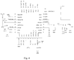
- the remote control comprises a remote control housing 6, and a control module, an antenna ANT, a first switch module, a second switch module and a third switch module which are installed in the remote control housing 6;
- the control module comprises a control chip U6;
- the control chip U6 has an output terminal coupled to the antenna ANT;
- the first switch module, the second switch module and the third switch module have a first switch 61, a second switch 62 and a third switch 63 respectively; and the first switch 61, the second switch 62 and the third switch 63 are coupled to an input terminal of the control chip U6, wherein the control chip U6 is a single chip with a model number of EFR32MG1P.
- the remote control further comprises a flash memory chip U7; and the flash memory chip U7 is coupled to the control chip U6.
- the control chip U6 outputs a control signal through the antenna ANT to the wireless repeater to control the smart curtain via wireless control.
- the smart curtain comprises a first casing 7; the curtain body 1 is coupled to the first casing 7; the motor module 2 is installed at the middle of the first casing 7; both ends of the motor module 2 have a first reel 72 and a second reel 73; the battery 3 and the wireless module are installed at an end of the first casing 7; the first reel 72 and the second reel 73 are transmitted with and coupled to the motor module 2; the first reel 72 and the second reel 73 are wound with a drawstring 74; the first casing 7 has a threading hole 71; and the drawstring 74 is passed through the threading hole 71 and then coupled to the curtain body 1.
- the smart curtain of this embodiment is a folding curtain or a Venetian curtain.
- users may use a remote control and a wireless repeater to send a command to the smart curtain, and the Zigbee chip U1 receives and processes a command and then sends the processed command (which is a serial command) through the interface P1 to the motor module 2 to rotate the motor module 2 in a forward or reverse direction, so that the first reel 72 and the second reel 73 at both ends of the motor module 2 are driven to rotate in a forward or reverse direction, and the drawstring 74 is wound on the first reel 72 and the second reel 73, or the drawstring 74 falls off from the first reel 72 and the second reel 73 to release or rewind the curtain body 1.
- a light strip 76 is embedded between the curtain body 1 and the first casing 7; the light strip 76 has a light emitting diode (LED) installed therein; the first casing 7 has an LED driving module installed therein and provided for driving the light emitting diode (LED) to emit light; the Zigbee chip U1 is provided for controlling the operation of the LED driving module; the light emitting diode (LED) comprises a R_LED, a G_LED and a B_LED; the LED driving module comprises a MOS tube Q4, a MOS tube Q5 and a MOS tube Q6; the R LED, G LED and B LED are passed through the MOS tube Q6, MOS tube Q5, and MOS tube Q4 respectively and then coupled to the output terminal of the Zigbee chip U1.
- the light emitting diode (LED) comprises a R_LED, a G_LED and a B_LED
- the LED driving module comprises a MOS tube Q4, a MOS tube Q5 and a MOS tube Q6
- the wireless electric curtain control system of this embodiment hides the light strip 76 in the curtain body 1 of the smart curtain, so that when the light strip 76 is lit, the color of the curtain body 1 can change with the color of the light strip 76.
- the Zigbee chip U1 controls the operation of the LED driving module after receiving a signal and triggers the light strip 76 to emit lights of different colors.
- the Zigbee chip U1 controls the operation of the LED driving module after receiving a signal, so as to control the operating status of the MOS tube Q4, the MOS tube Q5 and the MOS tube Q6 and turn on/off the R_LED, the G_LED and the B_LED, and drive the light strip 76 to emit lights of different colors.
- the first casing 7 is coupled to an external power adaptor 75; the power adaptor 75 is provided for supplying power to the wireless module; the wireless electric curtain control system of this embodiment not just charges the battery 3 through the solar module only, but also charges the battery 3 through the power adaptor 75.
- the power adaptor 75 is used for supplying power to the smart curtain directly.
- the motor module 2 has an output terminal coupled to a first gear 77; the second reel 73 has an input terminal coupled to a second gear 78 which his engaged with the first gear 77; and the second reel 73 and the first reel 72 are transmitted coaxially.
- the first casing 7 has a first cover 791 and a first battery compartment 79 for accommodating the battery 3; the first cover 791 has an end hinged to an end of the first battery compartment 79; the first cover 791 has a first elastic hook 792 disposed at the other end thereof; the other end of the first battery compartment 79 has a first slot 793 engaged with the first elastic hook 792; and when it is necessary to replace the battery 3, users just need to remove the first elastic hook 792 from the first slot 793 in order to open the first cover 791 of the first battery compartment 79 and complete the replacement of the battery 3.
- the first battery compartment 79 of this embodiment is made of plastic, and the plastic battery compartment 79 can avoid the shielding effect of the a metal battery compartment that interferes the transmission of the control signal.
- the smart curtain comprises a second casing 8 and a rotating shaft 81 rotatably coupled to the second casing 8; the curtain body 1 is wound on the rotating shaft 81; the motor module 2, the battery 3 and the wireless module are installed in the second casing 8; the motor module 2 has an output terminal transmitted and coupled with the rotating shaft 81; and the smart curtain further comprises a fixing mechanism 82 for fixing the second casing 8.
- the smart curtain of this embodiment is a roller blind.
- users may use a remote control and a wireless repeater to send a command to the smart curtain, and the Zigbee chip U1 receives and processes the command and then sends the processed command (which is a serial command) through the interface P1 to the motor module 2 to rotate the motor module 2 in a forward or reverse direction, so as to drive the curtain body 1 of the roller blind to ascend or descend.
- the fixing mechanism 82 is provided for fixing the second casing 8 on a wall or a window.
- the fixing mechanism 82 comprises an upper clamp 83 and a lower clamp 87 detachably coupled to the upper clamp 83;
- the upper clamp 83 has an upper clamping plate 84 disposed at the top thereof;
- the lower clamp 87 has a lower clamping plate 88 disposed at the bottom thereof;
- the upper clamp 83 has a snap slot 85;
- the lower clamp 87 has a pushing block and a snap slot 85 configured to be corresponsive to the elastic snap block 89; and a return spring 86 is installed between the pushing block and the upper clamp 83.
- the top of the lower clamping plate 88 is abutted against the bottom of the second casing 8 and the top of a fixing frame of the window is abutted against the bottom of the upper clamping plate 84, and then the upper clamp 83 and the lower clamp 87 are engaged until the elastic snap block 89 is engaged with the snap slot 85, so as to fix the casing on the fixing frame of the window.
- the users simply need to press the elastic snap block 89 to separate the elastic snap block 89 from the snap slot 85 in order to remove the second casing 8.
- the operation is simple and convenient. With the installation of the return spring 86, the second casing 8 can be removed more easily.
- the second casing 8 has a second cover 91 and a second battery compartment 9 for accommodating the battery 3; the second cover 91 has an end hinged to an end of the second battery compartment 9; the second cover 91 has a second elastic hook 92 disposed at the other end thereof; the second battery compartment 9 has a second slot 93 formed at the other end thereof and engaged with the second elastic hook 92.
- the users simply need to separate the second elastic hook 92 from the second slot 93 to open the second cover 91 of the second battery compartment 9 in order to change the battery 3,
- the second battery compartment 9 has an arc guide slot 94 for guiding the second cover 91 to rotate out from the second battery compartment 9. With the arc guide slot 94, the second cover 91 can be rotated and pushed out from the second battery compartment 9 to facilitate battery change.
- the second battery compartment 9 of this embodiment is made of plastic, and the plastic battery compartment can avoid the shielding effect of the a metal battery compartment that interferes the transmission of the control signal.
Landscapes
- Engineering & Computer Science (AREA)
- Structural Engineering (AREA)
- Architecture (AREA)
- Civil Engineering (AREA)
- Power Engineering (AREA)
- Computer Networks & Wireless Communication (AREA)
- Signal Processing (AREA)
- Physics & Mathematics (AREA)
- General Physics & Mathematics (AREA)
- Microelectronics & Electronic Packaging (AREA)
- General Engineering & Computer Science (AREA)
- Automation & Control Theory (AREA)
- Operating, Guiding And Securing Of Roll- Type Closing Members (AREA)
- Selective Calling Equipment (AREA)
- Curtains And Furnishings For Windows Or Doors (AREA)
Abstract
A wireless electric curtain control system includes a smart curtain, a wireless repeater and a remote control. The remote control is for sending a control signal to the wireless repeater; the wireless repeater is for receiving and sending the control signal to the smart curtain; the smart curtain includes a curtain body (1), a motor module (2) and a wireless module; the wireless module is for receiving and feeding back the control signal of the wireless repeater to a motor module (2); the motor module (2) controls the operation of the curtain body (1) according to the control signal received by the wireless module. The wireless repeater sends the control signal to the wireless module of the smart curtain to control the motor module (2) and the smart curtain and increase the signal transmission distance between the smart curtain and the remote control via a wireless transmission.
Description
- The present invention relates to the technical field of electric curtains, and more particularly to a wireless electric curtain control system.
- In general, a conventional commercial curtain controller controls its circuit by a simple power switch and/or button and just provides a basic curtain function only, but not a smart or wireless control function. As the people's living standard improves, people gradually pursue a high-quality lifestyle and ordinary curtains can no longer meet our requirement. Furthermore, ordinary curtains can only be controlled manually, and they provide only one operating mode and cannot be controlled automatically by a wireless device. This will bring tremendous inconvenience to our lives. Therefore, it is an important subject for related manufactures to solve the problem like this.
- It is a primary objective of the present invention to provide a wireless electric curtain control system to overcome the aforementioned drawbacks of the prior art.
- To achieve the aforementioned and other objectives, the present invention provides a wireless electric curtain control system comprising a smart curtain, a wireless repeater and a remote control; the remote control is provided for sending a control signal to the wireless repeater; the wireless repeater is provided for receiving the control signal for remote control and sending the control signal to the smart curtain; the smart curtain comprises a curtain body, a motor module, and a wireless module; the wireless module is provided for receiving the control signal of the wireless repeater and feeding back the control signal to the motor module; and the motor module controls the operation of the curtain body according to the control signal received by the wireless module.
- In the present invention, the smart curtain comprises a solar module, a battery and a charging circuit provided for a solar module to charge the battery.
- The charging circuit comprises a charging chip U3; the charging chip U3 has an interface P3 disposed at an input terminal thereof; the interface P3 is coupled to the solar module; the charging chip U3 has an interface P2 disposed at an output terminal thereof; the interface P2 is coupled to the battery; and the charging circuit has a first indicating light for indicating the charging status of the battery.
- In the present invention, the smart curtain further comprises a regulator module and a press button control module; the regulator module comprises a voltage regulator chip U2; the wireless module comprises a Zigbee chip U1; the press button control module comprises an ascending button S1 and a descending button S2; the voltage regulator chip U2 has an input terminal coupled to the battery; the voltage regulator chip U2 has an output terminal coupled to a power terminal of the Zigbee chip U1; the ascending button S1 and descending button S2 are coupled to two input terminal of the Zigbee chip U1 respectively; both ends of the ascending button S1 and both ends of the descending button S2 are coupled to a power supply and grounded; the Zigbee chip U1 has an output terminal coupled to an interface P1; and the interface P1 is coupled to the motor module.
- In the present invention, the wireless repeater comprises a repeater housing for installing a Zigbee chip U5 and a voltage regulator chip U4 therein; the voltage regulator chip U4 has an input terminal coupled to a power supply; the voltage regulator chip U4 has an output terminal coupled to a power terminal of the Zigbee chip U5; the wireless repeater further comprises a second indicating light for indicating the operating status of the wireless repeater; and the second indicating light is installed onto a surface of the repeater housing.
- In the present invention, the remote control comprises a remote control housing, and a control module, an antenna ANT, a first switch module, a second switch module and a third switch module which are installed in the remote control housing; the control module comprises a control chip U6; the control chip U6 has an output terminal coupled to the antenna ANT; the first switch module, the second switch module and the third switch module have a first switch, a second switch and a third switch respectively; the first switch, the second switch and the third switch are coupled to an input terminal of a control chip U6; the remote control further comprises a flash memory chip U7; and the flash memory chip U7 is coupled to the control chip U6.
- In the present invention, the smart curtain comprises a first casing; the curtain body is coupled to the first casing; the motor module is disposed at the middle of the first casing; both ends of the motor module have a first reel and a second reel respectively; the battery and the wireless module are installed at an end of the first casing; the first reel and the second reel are transmitted with and coupled to the motor module; both of the first reel and the second reel are wound with a drawstring; the first casing has a threading hole; and the drawstring is coupled to the curtain body after passing through the threading hole
- In the present invention, a light strip is embedded between the curtain body and the first casing; the light strip has a light emitting diode (LED) installed therein; the first casing has an LED driving module installed therein for driving the light emitting diode (LED) to emit light; the Zigbee chip U1 is provided for controlling the operation of the LED driving module; the light emitting diode (LED) comprises a R_LED, a G_LED and a B_LED; the LED driving module comprises a MOS tube Q4, a MOS tube Q5 and a MOS tube Q6; the R_LED, G_LED and B_LED are coupled to the output terminal of the Zigbee chip U1 after passing through the MOS tube Q6, the MOS tube Q5, and the MOS tube Q4 respectively.
- In the present invention, the first casing is coupled to an external power adaptor; the power adaptor is provided for supplying power to the wireless module; the motor module has an output terminal coupled to a first gear; the second reel has an input terminal coupled to a second gear which is engaged with the first gear; and the second reel and the first reel are transmitted coaxially; the first casing has a first cover and a first battery compartment for accommodating the battery; the first cover has an end hinged to an end of the first battery compartment; the other end of the first cover has a first elastic hook; and the other end of the first battery compartment has a first slot engaged with the first elastic hook; and the first battery compartment is made of plastic.
- In the present invention, the smart curtain comprises a second casing and a rotating shaft rotatably coupled to the second casing; the curtain body is wound on the rotating shaft; the motor module, the battery and the wireless module are installed in the second casing; the motor module has an output terminal transmitted with and coupled to the rotating shaft; and the smart curtain further comprises a fixing mechanism for fixing the second casing.
- In the present invention, the fixing mechanism comprises an upper clamp and a lower clamp detachably coupled to the upper clamp; the upper clamp has an upper clamping plate disposed at the top thereof; the lower clamp has a lower clamping plate disposed at the bottom thereof; the upper clamp has a snap slot; the lower clamp has an a pushing block and an elastic snap block corresponding to the snap slot; a return spring is installed between the pushing block and the upper clamp; the second casing has a second cover and a second battery compartment for accommodating the battery; the second cover has an end hinged to an end of the second battery compartment; the second cover has a second elastic hook disposed at the other end thereof; the other end of the second battery compartment has a second slot engaged with the second elastic hook; the second battery compartment has an arc guide slot provided for guiding the second cover to turn and move out from the second battery compartment; and the second battery compartment is made of plastic.
- The present invention has the following advantages: The wireless repeater transmits the control signal to the wireless module of the smart curtain to control the motor module by remote control without the need of transmitting signals between the wireless module of the smart curtain and the motor module continuously all the time, and thus the invention can save the power consumption of the smart curtain. When the smart curtain is not in use, the wireless module and the motor module of the smart curtain are in the power-saving sleep mode. After the remote control transmits the control signal to the wireless repeater, the wireless repeater sends a command to the wireless module of the smart curtain to control and turn on the wireless module and the motor module in order to control the curtain body to be released or rewound and to extend the standby duration of the smart curtain. In addition, this embodiment uses a repeater as a connecting member of the smart curtain and the remote control to increase the signal transmission distance between the smart curtain and the remote control via wireless transmission.
-
-
FIG. 1 is a circuit diagram of a wireless module of the present invention; -
FIG. 2 is a circuit diagram of a charging circuit of the present invention; -
FIG. 3 is a circuit diagram of a circuit including a Zigbee chip U5 and a voltage regulator chip U4 in accordance with the present invention; -
FIG. 4 is a circuit diagram of a control module of the present invention; -
FIG. 5 is a circuit diagram of a flash memory chip U7 of the present invention; -
FIG. 6 is a circuit diagram of a first switch module of the present invention; -
FIG. 7 is a perspective view of a remote control of the present invention; -
FIG. 8 is a perspective view of a wireless repeater of the present invention; -
FIG. 9 is a schematic view showing a first casing and a curtain body of the present invention; -
FIG. 10 is a schematic view showing the internal structure of a first casing of the present invention; -
FIG. 11 is a partial blowup view of Section A as depicted inFIG. 10 ; -
FIG. 12 is an exploded view showing a first cover and a first battery compartment in accordance with the present invention; -
FIG. 13 is a circuit diagram of an LED driving module of the present invention; -
FIG. 14 is a perspective view showing a second casing and a curtain body while a second cover is being hidden in accordance with the present invention; -
FIG. 15 is a perspective view showing a second casing when a rotating shaft is hidden in accordance with the present invention; -
FIG. 16 is an exploded view of a fixing mechanism of the present invention; and -
FIG. 17 is an exploded view showing a second cover and a second battery compartment of the present invention. - Wherein, a brief description of the components represented by their respective numerals in the drawings is given below. 1: curtain body; 2: motor module; 3: battery; 4: first indicating light; 5: repeater housing; 51: second indicating light; 6: remote control housing; 61: first switch; 62: second switch; 63: third switch; 7: first casing; 71: threading hole ; 72: first reel; 73: second reel; 74: drawstring; 75: power adaptor; 76: light strip; 77: first gear; 78: second gear; 79: first battery compartment; 791: first cover; 792: first elastic hook; 793: first slot; 8: second casing; 81: rotating shaft; 82: fixing mechanism; 83: upper clamp; 84: upper clamping plate; 85: snap slot ; 86: return spring; 87: lower clamp; 88: lower clamping plate; 89: elastic snap block; 9: second battery compartment; 91: second cover; 92: second elastic hook; 93: second slot; and 94: arc guide slot.
- The technical contents of the present invention will become apparent with the detailed description of preferred embodiments accompanied with the illustration of related drawings as follows. It is intended that the embodiments and figures disclosed herein are to be considered illustrative rather than restrictive.
- With reference to
FIGS. 1 to 8 for a wireless electric curtain control system in accordance with an embodiment of the present invention, the wireless electric curtain control system comprises a smart curtain, a wireless repeater and a remote control; the remote control is provided for sending a control signal to the wireless repeater; the wireless repeater is provided for receiving the control signal for remote control and sending the control signal to the smart curtain. - The smart curtain comprises a
curtain body 1, amotor module 2 and a wireless module, wherein themotor module 2 has a MCU installed therein; the wireless module is for receiving the control signal of a wireless repeater and feeding back the control signal to themotor module 2; and themotor module 2 controls the operation of thecurtain body 1 according to the control signal received by the wireless module. - Specifically, the wireless electric curtain control system of this embodiment uses a remote control to send the control signal from the wireless repeater to the wireless module of the smart curtain in order to control the
motor module 2 without the need of transmitting signals between the wireless module of the smart curtain and themotor module 2 continuously all the time, and thus the invention can save the power consumption of the smart curtain. - When the smart curtain is not in use, the wireless module and the
motor module 2 of the smart curtain are in the power-saving sleep mode. After the remote control transmits the control signal to the wireless repeater, the wireless repeater sends a command to the wireless module of the smart curtain to control and turn on the wireless module and themotor module 2 in order to control the curtain body to be released or rewound and to extend the standby duration of the smart curtain. In addition, this embodiment uses a repeater as a connecting member of the smart curtain and the remote control to increase the signal transmission distance between the smart curtain and the remote control via wireless transmission. - In the wireless electric curtain control system of this embodiment, the smart curtain comprises a solar module, a
battery 3, and a charging circuit provided for the solar module to charge thebattery 3. Wherein, the solar module is not shown in the figure. - The charging circuit comprises a charging chip U3; the charging chip U3 has an interface P3 at an input terminal thereof; the interface P3 is coupled to the solar module; the charging chip U3 also has an interface P2 at an output terminal thereof; the interface P2 is coupled to the
battery 3. - The charging circuit has a first indicating
light 4 for the charging status of the indicatingbattery 3. - In the wireless electric curtain control system of this embodiment, the solar module is provided for charging the
battery 3. Firstly, the interface P3 is a USB interface, and a 5V power of the solar module enters into an input terminal of the charging chip U3 through the interface P3, wherein the model number of the charging chip U3 is SY6982; the charging chip U3 converts the 5V power of the solar module into 8.4V power provided for charging thebattery 3 through the interface P2, wherein the interface P2 may be a USB interface of the battery compartment, and the first indicatinglight 4 is provided for indicating the charging status of thebattery 3. - In the wireless electric curtain control system of this embodiment, the smart curtain further comprises a regulator module and a press button control module.
- The regulator module comprises a voltage regulator chip U2; the wireless module comprises a Zigbee chip U1; the press button control module comprises an ascending button S1 and a descending button S2; the voltage regulator chip U2 has an input terminal coupled to the
battery 3; the voltage regulator chip U2 has an output terminal coupled to a power terminal of the Zigbee chip U1; the ascending button S1 and the descending button S2 are coupled to two input terminals of the Zigbee chip U1 respectively; both ends of the ascending button S1 and both ends of the descending button S2 are coupled to the power supply and grounded; the Zigbee chip U1 has an output terminal coupled to an interface P1; and the interface P1 is coupled to themotor module 2. - Specifically, the 8.4V power outputted from the
battery 3 is passed through the voltage regulator chip U2 and then supplied to the Zigbee chip U1, wherein the model number of the voltage regulator chip U2 is ME6203. - When it is necessary to release or rewind the
curtain body 1, a user may use a remote control to send a control signal from the wireless repeater to thecurtain body 1, and the Zigbee chip U1 receives and processes a command, and then sends the processed command (which is a serial command) through the interface P1 to themotor module 2 to rotate themotor module 2 in a forward or reverse direction. - In addition, the wireless electric curtain control system of this embodiment comprises the ascending button S1 and the descending button S2, so that users can control the
motor module 2 manually for a forward rotation or a reverse rotation. - In the wireless electric curtain control system of this embodiment, the wireless repeater comprises a
repeater housing 5, and a Zigbee chip U5 and a voltage regulator chip U4 which are installed in therepeater housing 5, wherein the model number of the voltage regulator chip U4 is ME6203; the voltage regulator chip U4 has an input terminal coupled to a power supply; the voltage regulator chip U4 has an output terminal coupled to a power terminal of the Zigbee chip U5; the wireless repeater further comprises a second indicatinglight 51 for indicating the operating status of the wireless repeater; and the second indicatinglight 51 is installed on a surface of therepeater housing 5. - Specifically, after the remote control sends a control signal, the Zigbee chip U5 of the wireless repeater receives and transfers the control signal to a Zigbee chip U1 of the smart curtain, and the second indicating
light 51 is provided to facilitate users to observe the operating status of the wireless repeater. - In the wireless electric curtain control system of this embodiment, the remote control comprises a
remote control housing 6, and a control module, an antenna ANT, a first switch module, a second switch module and a third switch module which are installed in theremote control housing 6; the control module comprises a control chip U6; the control chip U6 has an output terminal coupled to the antenna ANT; the first switch module, the second switch module and the third switch module have afirst switch 61, asecond switch 62 and athird switch 63 respectively; and thefirst switch 61, thesecond switch 62 and thethird switch 63 are coupled to an input terminal of the control chip U6, wherein the control chip U6 is a single chip with a model number of EFR32MG1P. - The remote control further comprises a flash memory chip U7; and the flash memory chip U7 is coupled to the control chip U6.
- Specifically, when a user wants to operate the wireless control smart curtain, the user presses the
first switch 61, thesecond switch 62 or thethird switch 63. After receiving a signal of thefirst switch 61, thesecond switch 62 or thethird switch 63, the control chip U6 outputs a control signal through the antenna ANT to the wireless repeater to control the smart curtain via wireless control. - In the wireless electric curtain control system of this embodiment as shown in
FIGS. 9 and13 , the smart curtain comprises afirst casing 7; thecurtain body 1 is coupled to thefirst casing 7; themotor module 2 is installed at the middle of thefirst casing 7; both ends of themotor module 2 have afirst reel 72 and asecond reel 73; thebattery 3 and the wireless module are installed at an end of thefirst casing 7; thefirst reel 72 and thesecond reel 73 are transmitted with and coupled to themotor module 2; thefirst reel 72 and thesecond reel 73 are wound with adrawstring 74; thefirst casing 7 has athreading hole 71; and thedrawstring 74 is passed through thethreading hole 71 and then coupled to thecurtain body 1. - Specifically, the smart curtain of this embodiment is a folding curtain or a Venetian curtain. When it is necessary to release or rewind the
curtain body 1, users may use a remote control and a wireless repeater to send a command to the smart curtain, and the Zigbee chip U1 receives and processes a command and then sends the processed command (which is a serial command) through the interface P1 to themotor module 2 to rotate themotor module 2 in a forward or reverse direction, so that thefirst reel 72 and thesecond reel 73 at both ends of themotor module 2 are driven to rotate in a forward or reverse direction, and thedrawstring 74 is wound on thefirst reel 72 and thesecond reel 73, or thedrawstring 74 falls off from thefirst reel 72 and thesecond reel 73 to release or rewind thecurtain body 1. - In the wireless electric curtain control system of this embodiment, a
light strip 76 is embedded between thecurtain body 1 and thefirst casing 7; thelight strip 76 has a light emitting diode (LED) installed therein; thefirst casing 7 has an LED driving module installed therein and provided for driving the light emitting diode (LED) to emit light; the Zigbee chip U1 is provided for controlling the operation of the LED driving module; the light emitting diode (LED) comprises a R_LED, a G_LED and a B_LED; the LED driving module comprises a MOS tube Q4, a MOS tube Q5 and a MOS tube Q6; the R LED, G LED and B LED are passed through the MOS tube Q6, MOS tube Q5, and MOS tube Q4 respectively and then coupled to the output terminal of the Zigbee chip U1. - Specifically, the wireless electric curtain control system of this embodiment hides the
light strip 76 in thecurtain body 1 of the smart curtain, so that when thelight strip 76 is lit, the color of thecurtain body 1 can change with the color of thelight strip 76. When it is necessary to control the color of thelight strip 76 by the wireless remote control, the Zigbee chip U1 controls the operation of the LED driving module after receiving a signal and triggers thelight strip 76 to emit lights of different colors. - Specifically, when it is necessary to change the color of the wireless remote control
light strip 76, the Zigbee chip U1 controls the operation of the LED driving module after receiving a signal, so as to control the operating status of the MOS tube Q4, the MOS tube Q5 and the MOS tube Q6 and turn on/off the R_LED, the G_LED and the B_LED, and drive thelight strip 76 to emit lights of different colors. - In the wireless electric curtain control system of this embodiment as shown in
FIGS. 14 and17 , thefirst casing 7 is coupled to anexternal power adaptor 75; thepower adaptor 75 is provided for supplying power to the wireless module; the wireless electric curtain control system of this embodiment not just charges thebattery 3 through the solar module only, but also charges thebattery 3 through thepower adaptor 75. When thebattery 3 is out of power, thepower adaptor 75 is used for supplying power to the smart curtain directly. - The
motor module 2 has an output terminal coupled to afirst gear 77; thesecond reel 73 has an input terminal coupled to asecond gear 78 which his engaged with thefirst gear 77; and thesecond reel 73 and thefirst reel 72 are transmitted coaxially. - The
first casing 7 has afirst cover 791 and afirst battery compartment 79 for accommodating thebattery 3; thefirst cover 791 has an end hinged to an end of thefirst battery compartment 79; thefirst cover 791 has a firstelastic hook 792 disposed at the other end thereof; the other end of thefirst battery compartment 79 has afirst slot 793 engaged with the firstelastic hook 792; and when it is necessary to replace thebattery 3, users just need to remove the firstelastic hook 792 from thefirst slot 793 in order to open thefirst cover 791 of thefirst battery compartment 79 and complete the replacement of thebattery 3. - Compared with the battery compartment made of metal, the
first battery compartment 79 of this embodiment is made of plastic, and theplastic battery compartment 79 can avoid the shielding effect of the a metal battery compartment that interferes the transmission of the control signal. - In the wireless electric curtain control system of this embodiment, the smart curtain comprises a
second casing 8 and arotating shaft 81 rotatably coupled to thesecond casing 8; thecurtain body 1 is wound on therotating shaft 81; themotor module 2, thebattery 3 and the wireless module are installed in thesecond casing 8; themotor module 2 has an output terminal transmitted and coupled with the rotatingshaft 81; and the smart curtain further comprises afixing mechanism 82 for fixing thesecond casing 8. - Specifically, the smart curtain of this embodiment is a roller blind. When it is necessary to release or rewind the
curtain body 1, users may use a remote control and a wireless repeater to send a command to the smart curtain, and the Zigbee chip U1 receives and processes the command and then sends the processed command (which is a serial command) through the interface P1 to themotor module 2 to rotate themotor module 2 in a forward or reverse direction, so as to drive thecurtain body 1 of the roller blind to ascend or descend. In addition, the fixingmechanism 82 is provided for fixing thesecond casing 8 on a wall or a window. - In the wireless electric curtain control system of this embodiment, the fixing
mechanism 82 comprises anupper clamp 83 and alower clamp 87 detachably coupled to theupper clamp 83; theupper clamp 83 has anupper clamping plate 84 disposed at the top thereof; thelower clamp 87 has alower clamping plate 88 disposed at the bottom thereof; theupper clamp 83 has asnap slot 85; thelower clamp 87 has a pushing block and asnap slot 85 configured to be corresponsive to theelastic snap block 89; and areturn spring 86 is installed between the pushing block and theupper clamp 83. When it is necessary to fix the wireless electric curtain control system of this embodiment on a wall or a window, the top of thelower clamping plate 88 is abutted against the bottom of thesecond casing 8 and the top of a fixing frame of the window is abutted against the bottom of theupper clamping plate 84, and then theupper clamp 83 and thelower clamp 87 are engaged until theelastic snap block 89 is engaged with thesnap slot 85, so as to fix the casing on the fixing frame of the window. When it is necessary to remove thesecond casing 8 from the fixing frame of the window, the users simply need to press theelastic snap block 89 to separate theelastic snap block 89 from thesnap slot 85 in order to remove thesecond casing 8. The operation is simple and convenient. With the installation of thereturn spring 86, thesecond casing 8 can be removed more easily. - The
second casing 8 has asecond cover 91 and asecond battery compartment 9 for accommodating thebattery 3; thesecond cover 91 has an end hinged to an end of thesecond battery compartment 9; thesecond cover 91 has a secondelastic hook 92 disposed at the other end thereof; thesecond battery compartment 9 has asecond slot 93 formed at the other end thereof and engaged with the secondelastic hook 92. When it is necessary to change thebattery 3, the users simply need to separate the secondelastic hook 92 from thesecond slot 93 to open thesecond cover 91 of thesecond battery compartment 9 in order to change thebattery 3, - The
second battery compartment 9 has anarc guide slot 94 for guiding thesecond cover 91 to rotate out from thesecond battery compartment 9. With thearc guide slot 94, thesecond cover 91 can be rotated and pushed out from thesecond battery compartment 9 to facilitate battery change. - Compared with the battery compartment made of metal, the
second battery compartment 9 of this embodiment is made of plastic, and the plastic battery compartment can avoid the shielding effect of the a metal battery compartment that interferes the transmission of the control signal. - While the invention has been described by means of specific embodiments, numerous modifications and variations could be made thereto by those skilled in the art without departing from the scope and spirit of the invention set forth in the claims.
Claims (10)
- A wireless electric curtain control system, comprising a smart curtain, a wireless repeater and a remote control; the remote control being provided for sending a control signal to the wireless repeater; the wireless repeater being provided for receiving the control signal for remote control and sending the control signal to the smart curtain;
the smart curtain comprising a curtain body (1), a motor module (2), and a wireless module; the wireless module being provided for receiving the control signal of the wireless repeater and feeding back the control signal of the wireless repeater to the motor module (2); and
the motor module (2) controlling the operation of the curtain body (1) according to the control signal received by the wireless module. - The wireless electric curtain control system according to claim 1, wherein the smart curtain comprises a solar module, a battery (3) and a charging circuit provided for the solar module to charge the battery (3); the charging circuit comprises a charging chip U3; the charging chip U3 has an interface P3 disposed at an input terminal thereof; the interface P3 is coupled to the solar module; the charging chip U3 has an interface P2 disposed at an output terminal thereof; the interface P2 is coupled to the battery (3); and the charging circuit has a first indicating light (4) for indicating the charging status of the battery (3).
- The wireless electric curtain control system according to claim 2, wherein the smart curtain further comprises a regulator module and a press button control module; the regulator module comprises a voltage regulator chip U2; the wireless module comprises a Zigbee chip U1; the press button control module comprises an ascending button S1 and a descending button S2; the voltage regulator chip U2 has an input terminal coupled to the battery (3); the voltage regulator chip U2 has an output terminal coupled to a power terminal of the Zigbee chip U1; the ascending button S1 and the descending button S2 are coupled to two input terminals of the Zigbee chip U1 respectively; both ends of the ascending button S1 and both ends of the descending button S2 are coupled to a power supply and grounded; the Zigbee chip U1 has an output terminal coupled to an interface P1; and the interface P1 is coupled to the motor module (2).
- The wireless electric curtain control system according to claim 1, wherein the wireless repeater comprises a repeater housing (5) for installing a Zigbee chip U5 and a voltage regulator chip U4 therein; the voltage regulator chip U4 has an input terminal coupled to a power supply; the voltage regulator chip U4 has an output terminal coupled to a power terminal of the Zigbee chip U5; the wireless repeater further comprises a second indicating light (51) for indicating the operating status of the wireless repeater; and the second indicating light (51) is installed onto a surface of the repeater housing (5).
- The wireless electric curtain control system according to claim 1, wherein the remote control comprises a remote control housing (6) and a control module, an antenna ANT, a first switch module, a second switch module and a third switch module which are installed in the remote control housing (6); the control module comprises a control chip U6; the control chip U6 has an output terminal coupled to the antenna ANT; the first switch module, the second switch module and the third switch module have a first switch (61), a second switch (62) and a third switch (63) respectively; the first switch (61), the second switch (62) and the third switch (63) are coupled to an input terminal of a control chip U6; the remote control further comprises a flash memory chip U7; and the flash memory chip U7 is coupled to the control chip U6.
- The wireless electric curtain control system according to claim 3, wherein the smart curtain comprises a first casing (7); the curtain body (1) is coupled to the first casing (7); the motor module (2) is disposed at the middle of the first casing (7); both ends of the motor module (2) have a first reel (72) and a second reel (73) respectively; the battery (3) and the wireless module are installed at an end of the first casing (7); the first reel (72) and the second reel (73) are transmitted with and coupled to the motor module (2); both of the first reel (72) and the second reel (73) are wound with a drawstring (74); the first casing (7) has a threading hole (71); and the drawstring (74) is coupled to the curtain body (1) after passing through threading hole (71).
- The wireless electric curtain control system according to claim 6, wherein a light strip (76) is embedded between the curtain body (1) and the first casing (7); the light strip (76) has a light emitting diode (LED) installed therein; the first casing (7) has an LED driving module installed therein for driving the light emitting diode (LED) to emit light; the Zigbee chip U1 is provided for controlling the operation of the LED driving module; the light emitting diode (LED) comprises a R LED, a G LED and a B_LED; the LED driving module comprises a MOS tube Q4, a MOS tube Q5 and a MOS tube Q6; the R_LED, G_LED and B LED are coupled to the output terminal of the Zigbee chip U1 after passing through the MOS tube Q6, the MOS tube Q5, and the MOS tube Q4 respectively.
- The wireless electric curtain control system according to claim 6, wherein the first casing (7) is coupled to an external power adaptor (75); the power adaptor (75) is provided for supplying power to the wireless module; the motor module (2) has an output terminal coupled to a first gear (77); the second reel (73) has an input terminal coupled to a second gear (78) which is engaged with the first gear (77); the second reel (73) and the first reel (72) are transmitted coaxially; the first casing (7) has a first cover (791) and a first battery compartment (79) for accommodating the battery (3); the first cover (791) has an end hinged to an end of the first battery compartment (79); the other end of the first cover (791) has a first elastic hook (792); the other end of the first battery compartment (79) has a first slot (793) engaged with the first elastic hook (792); and the first battery compartment (79) is made of plastic.
- The wireless electric curtain control system according to claim 3, wherein the smart curtain comprises a second casing (8) and a rotating shaft (81) rotatably coupled to the second casing (8); the curtain body (1) is wound on the rotating shaft (81); the motor module (2), the battery (3) and the wireless module are installed in the second casing (8); the motor module (2) has an output terminal transmitted with and coupled to the rotating shaft (81); and the smart curtain further comprises a fixing mechanism (82) for fixing the second casing (8).
- The wireless electric curtain control system according to claim 9, wherein the fixing mechanism (82) comprises an upper clamp (83) and a lower clamp (87) detachably coupled to the upper clamp (83); the upper clamp (83) has an upper clamping plate (84) disposed at the top thereof; the lower clamp (87) has a lower clamping plate (88) disposed at the bottom thereof; the upper clamp (83) has a snap slot (85); the lower clamp (87) has an a pushing block and an elastic snap block (89) corresponding to the snap slot (85); a return spring (86) is installed between the pushing block and the upper clamp (83); the second casing (8) has a second cover (91) and a second battery compartment (9) for accommodating the battery (3); the second cover (91) has an end hinged to an end of the second battery compartment (9); the second cover (91) has a second elastic hook (92) disposed at the other end thereof; the other end of the second battery compartment (9) has a second slot (93) engaged with the second elastic hook (92); the second battery compartment (9) has an arc guide slot (94) provided for guiding the second cover (91) to turn and move out from the second battery compartment (9); and the second battery compartment (9) is made of plastic.
Applications Claiming Priority (1)
| Application Number | Priority Date | Filing Date | Title |
|---|---|---|---|
| CN201910318456.5A CN110005331B (en) | 2019-04-19 | 2019-04-19 | Wireless electric curtain control system |
Publications (1)
| Publication Number | Publication Date |
|---|---|
| EP3726697A1 true EP3726697A1 (en) | 2020-10-21 |
Family
ID=66793771
Family Applications (1)
| Application Number | Title | Priority Date | Filing Date |
|---|---|---|---|
| EP19178352.1A Withdrawn EP3726697A1 (en) | 2019-04-19 | 2019-06-05 | Wireless electric curtain control system |
Country Status (3)
| Country | Link |
|---|---|
| US (1) | US11203897B2 (en) |
| EP (1) | EP3726697A1 (en) |
| CN (1) | CN110005331B (en) |
Cited By (2)
| Publication number | Priority date | Publication date | Assignee | Title |
|---|---|---|---|---|
| CN113413055A (en) * | 2021-01-14 | 2021-09-21 | 李玉兰 | WIFI low-power consumption electric window curtain driving device |
| US11203897B2 (en) * | 2019-04-19 | 2021-12-21 | Dongguang Keetat Lighting Ltd. | Wireless electric curtain control system |
Families Citing this family (10)
| Publication number | Priority date | Publication date | Assignee | Title |
|---|---|---|---|---|
| US11146085B2 (en) | 2017-04-17 | 2021-10-12 | Nien Made Enterprise Co., Ltd. | Charging system for electric window covering |
| EP3828374B1 (en) * | 2019-11-28 | 2025-08-20 | Nien Made Enterprise Co., Ltd. | Electric window covering |
| CN112271779A (en) * | 2020-10-28 | 2021-01-26 | 广东奥科伟业科技发展有限公司 | A charging system with built-in battery electric curtain |
| US11353177B1 (en) * | 2021-04-16 | 2022-06-07 | Shenzhen Ekola Lighting Technology Co., Ltd. | Smart curtain light strings |
| US20220333438A1 (en) * | 2021-04-19 | 2022-10-20 | Teh Yor Co., Ltd. | Support structure and electrically-driven window shade including the same |
| CN113380019B (en) * | 2021-07-14 | 2022-06-14 | 厦门市沧鹏电子科技有限公司 | Copy remote controller control circuit capable of remotely copying remote controller signals |
| CN217285398U (en) * | 2021-12-21 | 2022-08-26 | 宁波森瑞机电技术有限公司 | Curtain driving device |
| US12291922B2 (en) * | 2022-08-03 | 2025-05-06 | Yan Chen | Integrated control type hollow curtain |
| US20240098515A1 (en) * | 2022-09-15 | 2024-03-21 | At&T Intellectual Property I, L.P. | Automated Orienting of Customer Premises Equipment |
| CN116019343A (en) * | 2022-12-07 | 2023-04-28 | 宁波森瑞机电技术有限公司 | A convenient and quick assembly electric ceiling curtain |
Citations (2)
| Publication number | Priority date | Publication date | Assignee | Title |
|---|---|---|---|---|
| US20090308543A1 (en) * | 2008-06-13 | 2009-12-17 | Lawrence Kates | Motorized window shade system and mount |
| CN204654547U (en) * | 2015-04-14 | 2015-09-23 | 福州中琦电子科技有限公司 | Long-distance Control blind system |
Family Cites Families (28)
| Publication number | Priority date | Publication date | Assignee | Title |
|---|---|---|---|---|
| US6812662B1 (en) * | 2002-04-01 | 2004-11-02 | Harmonic Design, Inc. | Photoelectric power supply system for motorized window coverings |
| US6983783B2 (en) * | 2003-06-10 | 2006-01-10 | Lutron Electronics Co., Inc. | Motorized shade control system |
| JP2007023643A (en) * | 2005-07-19 | 2007-02-01 | Yokota Riyouhan Kk | Mounting bracket for roll screen and the like |
| US8395496B2 (en) * | 2007-03-29 | 2013-03-12 | Shiv P Joshi | Miniature modular wireless sensor |
| CN201624500U (en) * | 2010-02-01 | 2010-11-10 | 中南林业科技大学 | Intelligent remote control curtain |
| CN201865548U (en) * | 2010-10-09 | 2011-06-15 | 林浩 | Louver arranged in hollow glass |
| US10655386B2 (en) * | 2011-03-11 | 2020-05-19 | Lutron Technology Company Llc | Motorized window treatment |
| US9810020B2 (en) * | 2011-03-11 | 2017-11-07 | Lutron Electronics Co., Inc. | Motorized window treatment |
| WO2012125423A1 (en) * | 2011-03-11 | 2012-09-20 | Lutron Electronics Co., Inc. | Low power radio frequency receiver |
| CN202391326U (en) * | 2011-11-29 | 2012-08-22 | 宁波杜亚机电技术有限公司 | Electric window curtain with double output shafts |
| WO2014169093A1 (en) * | 2013-04-11 | 2014-10-16 | Qmotion Incorporated | Motorized drapery apparatus, system and method of use |
| CN203054503U (en) * | 2012-12-09 | 2013-07-10 | 成都卓程科技有限公司 | Intelligent curtain control system based on single-chip microcomputer |
| CN103654257B (en) * | 2013-12-03 | 2015-10-28 | 大连大学 | Curtain intelligent control system based on ZigBee |
| CN103763590A (en) * | 2013-12-18 | 2014-04-30 | 深圳市共进电子股份有限公司 | Intelligent set top box integrating Zigbee |
| US10358869B2 (en) * | 2014-06-17 | 2019-07-23 | Crestron Electronics, Inc. | Shading control network using a control network |
| CN204028656U (en) * | 2014-06-17 | 2014-12-17 | 九州方圆实业控股(集团)有限公司 | A kind of intelligent home control system |
| US10072458B2 (en) * | 2014-12-16 | 2018-09-11 | Current Products Corp | Remote controlled motorized wand for controlling blinds |
| CN204260487U (en) * | 2014-12-19 | 2015-04-15 | 南京化工职业技术学院 | A kind of solar energy curtain controller |
| CN204862530U (en) * | 2015-06-27 | 2015-12-16 | 姜月 | Novel (window) curtain hangs device |
| CN105064901A (en) * | 2015-08-21 | 2015-11-18 | 湖州高鼎智能科技有限公司 | Intelligent curtain control system |
| CN205006587U (en) * | 2015-08-31 | 2016-02-03 | 厦门网拓科技有限公司 | Intelligence curtain control system |
| CN206565732U (en) * | 2016-06-21 | 2017-10-20 | 新昌县城关欣荣轴承厂 | A kind of multi-mode control light regulation curtain |
| CN206071435U (en) * | 2016-08-31 | 2017-04-05 | 四川信息职业技术学院 | It is a kind of to be based on monolithic processor controlled intelligent distant control curtain |
| US20190100961A1 (en) * | 2017-03-27 | 2019-04-04 | Ben Kutell | Motorized roller shade configurations, systems, methods of use, and installation |
| CN207160942U (en) * | 2017-09-10 | 2018-03-30 | 韩帅 | Multi-functional shutter curtain |
| CN207553943U (en) * | 2017-12-11 | 2018-06-29 | 宁波梦居智能科技有限公司 | The electrically driven curtain of multi-mode control |
| CN210659871U (en) * | 2019-04-19 | 2020-06-02 | 东莞健达照明有限公司 | Wireless electric curtain control system |
| CN110005331B (en) * | 2019-04-19 | 2022-05-24 | 健达创智科技股份有限公司 | Wireless electric curtain control system |
-
2019
- 2019-04-19 CN CN201910318456.5A patent/CN110005331B/en active Active
- 2019-06-05 EP EP19178352.1A patent/EP3726697A1/en not_active Withdrawn
- 2019-06-24 US US16/450,392 patent/US11203897B2/en not_active Expired - Fee Related
Patent Citations (2)
| Publication number | Priority date | Publication date | Assignee | Title |
|---|---|---|---|---|
| US20090308543A1 (en) * | 2008-06-13 | 2009-12-17 | Lawrence Kates | Motorized window shade system and mount |
| CN204654547U (en) * | 2015-04-14 | 2015-09-23 | 福州中琦电子科技有限公司 | Long-distance Control blind system |
Cited By (2)
| Publication number | Priority date | Publication date | Assignee | Title |
|---|---|---|---|---|
| US11203897B2 (en) * | 2019-04-19 | 2021-12-21 | Dongguang Keetat Lighting Ltd. | Wireless electric curtain control system |
| CN113413055A (en) * | 2021-01-14 | 2021-09-21 | 李玉兰 | WIFI low-power consumption electric window curtain driving device |
Also Published As
| Publication number | Publication date |
|---|---|
| CN110005331B (en) | 2022-05-24 |
| US11203897B2 (en) | 2021-12-21 |
| US20200332594A1 (en) | 2020-10-22 |
| CN110005331A (en) | 2019-07-12 |
Similar Documents
| Publication | Publication Date | Title |
|---|---|---|
| US11203897B2 (en) | Wireless electric curtain control system | |
| CN100419931C (en) | Switch with light control function | |
| US6299115B1 (en) | Remote control operating system and support structure for a retractable covering for an architectural opening | |
| CN103620150B (en) | Electric Curtain Handling Device | |
| US11739533B2 (en) | Control device for the lighting elements to be mounted on a roller covering installation | |
| CN107770337A (en) | A kind of automatic intelligent handset mounting and application method | |
| US6910515B2 (en) | Electricity-operated window blind | |
| CN210659871U (en) | Wireless electric curtain control system | |
| US8575877B2 (en) | Solar-powered window covering automation system | |
| GB2469765A (en) | Power circuit responsive to load | |
| CN215820541U (en) | Curtain opening and closing device and curtain opening and closing system | |
| EP1500776A2 (en) | Electricity-operated window blind | |
| KR20190062986A (en) | Apparatus for switch on-off | |
| CN208473673U (en) | A kind of library's curtain reels device automatically | |
| CN217684605U (en) | Intelligent down lamp | |
| CN205206711U (en) | Roll up curtain controller | |
| CN212929812U (en) | Night vision LED lamp | |
| JP2001210479A (en) | Infrared power supply switch | |
| CN215528743U (en) | Tubular electric motor | |
| CN210835638U (en) | Remote switch device | |
| CN223501317U (en) | A smart control circuit for curtains | |
| CN211777116U (en) | External chain motor lighting device | |
| CN218483514U (en) | Shaving equipment convenient to use | |
| CN222888035U (en) | Tubular motor | |
| CN219961090U (en) | Convenient to use's intelligent curtain controller that draws pearl |
Legal Events
| Date | Code | Title | Description |
|---|---|---|---|
| PUAI | Public reference made under article 153(3) epc to a published international application that has entered the european phase |
Free format text: ORIGINAL CODE: 0009012 |
|
| STAA | Information on the status of an ep patent application or granted ep patent |
Free format text: STATUS: THE APPLICATION HAS BEEN PUBLISHED |
|
| AK | Designated contracting states |
Kind code of ref document: A1 Designated state(s): AL AT BE BG CH CY CZ DE DK EE ES FI FR GB GR HR HU IE IS IT LI LT LU LV MC MK MT NL NO PL PT RO RS SE SI SK SM TR |
|
| AX | Request for extension of the european patent |
Extension state: BA ME |
|
| STAA | Information on the status of an ep patent application or granted ep patent |
Free format text: STATUS: THE APPLICATION IS DEEMED TO BE WITHDRAWN |
|
| 18D | Application deemed to be withdrawn |
Effective date: 20210422 |