EP3726670B1 - Connector with grommet - Google Patents
Connector with grommet Download PDFInfo
- Publication number
- EP3726670B1 EP3726670B1 EP20169759.6A EP20169759A EP3726670B1 EP 3726670 B1 EP3726670 B1 EP 3726670B1 EP 20169759 A EP20169759 A EP 20169759A EP 3726670 B1 EP3726670 B1 EP 3726670B1
- Authority
- EP
- European Patent Office
- Prior art keywords
- panel
- locking
- locked
- connector
- flange
- Prior art date
- Legal status (The legal status is an assumption and is not a legal conclusion. Google has not performed a legal analysis and makes no representation as to the accuracy of the status listed.)
- Active
Links
Images





Classifications
-
- H—ELECTRICITY
- H01—ELECTRIC ELEMENTS
- H01R—ELECTRICALLY-CONDUCTIVE CONNECTIONS; STRUCTURAL ASSOCIATIONS OF A PLURALITY OF MUTUALLY-INSULATED ELECTRICAL CONNECTING ELEMENTS; COUPLING DEVICES; CURRENT COLLECTORS
- H01R13/00—Details of coupling devices of the kinds covered by groups H01R12/70 or H01R24/00 - H01R33/00
- H01R13/73—Means for mounting coupling parts to apparatus or structures, e.g. to a wall
- H01R13/74—Means for mounting coupling parts in openings of a panel
- H01R13/741—Means for mounting coupling parts in openings of a panel using snap fastening means
-
- H—ELECTRICITY
- H01—ELECTRIC ELEMENTS
- H01R—ELECTRICALLY-CONDUCTIVE CONNECTIONS; STRUCTURAL ASSOCIATIONS OF A PLURALITY OF MUTUALLY-INSULATED ELECTRICAL CONNECTING ELEMENTS; COUPLING DEVICES; CURRENT COLLECTORS
- H01R13/00—Details of coupling devices of the kinds covered by groups H01R12/70 or H01R24/00 - H01R33/00
- H01R13/73—Means for mounting coupling parts to apparatus or structures, e.g. to a wall
- H01R13/74—Means for mounting coupling parts in openings of a panel
- H01R13/741—Means for mounting coupling parts in openings of a panel using snap fastening means
- H01R13/743—Means for mounting coupling parts in openings of a panel using snap fastening means integral with the housing
-
- H—ELECTRICITY
- H01—ELECTRIC ELEMENTS
- H01R—ELECTRICALLY-CONDUCTIVE CONNECTIONS; STRUCTURAL ASSOCIATIONS OF A PLURALITY OF MUTUALLY-INSULATED ELECTRICAL CONNECTING ELEMENTS; COUPLING DEVICES; CURRENT COLLECTORS
- H01R13/00—Details of coupling devices of the kinds covered by groups H01R12/70 or H01R24/00 - H01R33/00
- H01R13/46—Bases; Cases
- H01R13/52—Dustproof, splashproof, drip-proof, waterproof, or flameproof cases
- H01R13/5213—Covers
-
- B—PERFORMING OPERATIONS; TRANSPORTING
- B60—VEHICLES IN GENERAL
- B60R—VEHICLES, VEHICLE FITTINGS, OR VEHICLE PARTS, NOT OTHERWISE PROVIDED FOR
- B60R16/00—Electric or fluid circuits specially adapted for vehicles and not otherwise provided for; Arrangement of elements of electric or fluid circuits specially adapted for vehicles and not otherwise provided for
- B60R16/02—Electric or fluid circuits specially adapted for vehicles and not otherwise provided for; Arrangement of elements of electric or fluid circuits specially adapted for vehicles and not otherwise provided for electric constitutive elements
- B60R16/0207—Wire harnesses
- B60R16/0215—Protecting, fastening and routing means therefor
- B60R16/0222—Grommets
-
- H—ELECTRICITY
- H01—ELECTRIC ELEMENTS
- H01R—ELECTRICALLY-CONDUCTIVE CONNECTIONS; STRUCTURAL ASSOCIATIONS OF A PLURALITY OF MUTUALLY-INSULATED ELECTRICAL CONNECTING ELEMENTS; COUPLING DEVICES; CURRENT COLLECTORS
- H01R13/00—Details of coupling devices of the kinds covered by groups H01R12/70 or H01R24/00 - H01R33/00
- H01R13/46—Bases; Cases
- H01R13/52—Dustproof, splashproof, drip-proof, waterproof, or flameproof cases
- H01R13/5202—Sealing means between parts of housing or between housing part and a wall, e.g. sealing rings
-
- H—ELECTRICITY
- H01—ELECTRIC ELEMENTS
- H01R—ELECTRICALLY-CONDUCTIVE CONNECTIONS; STRUCTURAL ASSOCIATIONS OF A PLURALITY OF MUTUALLY-INSULATED ELECTRICAL CONNECTING ELEMENTS; COUPLING DEVICES; CURRENT COLLECTORS
- H01R13/00—Details of coupling devices of the kinds covered by groups H01R12/70 or H01R24/00 - H01R33/00
- H01R13/64—Means for preventing incorrect coupling
- H01R13/641—Means for preventing incorrect coupling by indicating incorrect coupling; by indicating correct or full engagement
-
- H—ELECTRICITY
- H01—ELECTRIC ELEMENTS
- H01R—ELECTRICALLY-CONDUCTIVE CONNECTIONS; STRUCTURAL ASSOCIATIONS OF A PLURALITY OF MUTUALLY-INSULATED ELECTRICAL CONNECTING ELEMENTS; COUPLING DEVICES; CURRENT COLLECTORS
- H01R13/00—Details of coupling devices of the kinds covered by groups H01R12/70 or H01R24/00 - H01R33/00
- H01R13/62—Means for facilitating engagement or disengagement of coupling parts or for holding them in engagement
- H01R13/629—Additional means for facilitating engagement or disengagement of coupling parts, e.g. aligning or guiding means, levers, gas pressure electrical locking indicators, manufacturing tolerances
- H01R13/62933—Comprising exclusively pivoting lever
- H01R13/62938—Pivoting lever comprising own camming means
-
- H—ELECTRICITY
- H01—ELECTRIC ELEMENTS
- H01R—ELECTRICALLY-CONDUCTIVE CONNECTIONS; STRUCTURAL ASSOCIATIONS OF A PLURALITY OF MUTUALLY-INSULATED ELECTRICAL CONNECTING ELEMENTS; COUPLING DEVICES; CURRENT COLLECTORS
- H01R2201/00—Connectors or connections adapted for particular applications
- H01R2201/26—Connectors or connections adapted for particular applications for vehicles
Definitions
- the present invention relates to a connector with a grommet.
- a connector with a grommet to be attached to a panel of an automobile is disclosed in, for example, JP 2015-222667 A .
- the connector with a grommet includes a connector housing (housing) and a grommet configured to cover an outer circumference of the connector housing.
- a lock projection (locking projection) of the connector housing is located in a mounting hole of a vehicle body panel (panel)
- a sensing piece of the connector housing tilts and presses a thin part of the grommet. Accordingly, the thin part of the grommet bulges.
- the sensing piece of the housing tilts, the sensing piece is covered with the thin part of the grommet, so that the thin part of the grommet bulges only slightly.
- a connector with a grommet including: a housing including a panel hooking portion that is hooked on an edge of a mounting hole of a panel and is locked to the edge, an annular flange that faces the edge, and a locking projection that is locked to the panel by sandwiching the panel between the locking projection and the flange, wherein the panel hooking portion, the flange, and the locking projection are formed on an outside of the housing; a grommet including a panel contact part that is fitted into the flange so as to cover the flange and comes into tight contact with the edge; and a sensing member inserted into an insertion hole formed in the flange and including a part located outward than the insertion hole, the part of the sensing member being received in a receiving part formed on the panel contact part, the sensing member being pushed out by the panel to move to an outside of the flange when the locking projection is locked to the panel, to sense a locked state of the locking projection, wherein the housing is provided with
- the sensing member when the locking projection of the housing is locked to the panel, the sensing member is pushed out by the panel to move to the outside of the flange, so that the fact that the locking projection is locked to the panel can be visually confirmed easily and reliably.
- FIGS. 1 to 21 A first embodiment of the present invention will be described with reference to FIGS. 1 to 21 .
- the lever-type connector 10 includes a male connector 20 and a female connector (connector with a grommet) 50.
- the male connector 20 is arranged on an inside of a vehicle body panel (panel) 11 (a side opposite to a door side).
- the female connector 50 is arranged on an outside of the vehicle body panel 11 (door side).
- the male connector 20 includes a male housing 21 made of a synthetic resin, a lever 30 made of a synthetic resin and a cable cover 40 made of a synthetic resin.
- the male housing 21 houses a plurality of male terminals (terminals), not illustrated, and is fitted into and disengaged from a female housing 51 of the female connector 50.
- the lever 30 is pivotably supported and slidably supported by the male housing 21 via support shafts 24 and 24 (only one support shaft 24 is illustrated in FIGS. 1 and 4 ).
- the lever 30 fits and disengages the male housing 21 and the female housing 51 by a pivoting operation.
- the cable cover 40 is mounted on the male housing 21 so as to cover a rear side of the male housing 21 (a side opposite to a side where the male connector 20 faces the female connector 50).
- the male housing 21 includes a housing body 22 having a rectangular block shape and a hood portion 23.
- the housing body 22 includes a plurality of terminal receiving holes 22a which receives male terminals.
- the hood portion 23 is formed integrally on the front side of the housing body 22 (the side where the male connector 20 faces the female connector 50) so as to protrude therefrom.
- a housing body 52 of the female housing 51 is fitted into the hood portion 23.
- the support shafts 24 and 24 extending in a direction perpendicular to a fitting direction of the connector are integrally formed so as to respectively protrude from boundaries between centers of side surfaces 22b and 22b on both sides of the housing body 22 and the hood portion 23.
- the support shafts 24 and 24 are pivot shafts of the lever 30.
- Guide projections 25 and 25 are integrally formed on the rear side of side surfaces 22b and 22b on both sides of the housing body 22 (the side opposite to the side where the male connector 20 faces the female connector 50) so as to protrude therefrom, and at a position near an operation portion 31 of the lever 30, described later. As illustrated in FIG.
- temporary locking recesses (temporary locked portions) 26 and 26 and final locking recesses (final locked portions) 27 and 27 are respectively formed on the hood portion 23 and the side surfaces 22b and 22b on both sides of the housing body 22, at positions corresponding to trajectories of the pivotal movements of projecting portions 39a and 39a of locking arms (locking portions) 39 and 39 of the lever 30, described later (only one temporary locking recess 26 and one final locking recess 27 are illustrated in FIG. 2 ).
- the lever 30 is mounted on the male housing 21 so as to cover a part of the male housing 21 of the male connector 20 and a part of the cable cover 40.
- the lever 30 pulls the male connector 20 and the female connector 50 toward each other by the pivoting operation from a lever pivot start position illustrated in FIG. 14A to a lever pivot completion position illustrated in FIG. 15A , to fit the male connector 20 and the female connector 50.
- the lever 30 includes the operation portion 31 and a pair of arm portions 32 and 32 extending from both sides of the operation portion 31.
- a bearing hole (bearing portion) 33 is formed at a center of each arm portion 32 of the lever 30.
- the bearing hole 33 includes a shaft sliding groove 34 in which the support shaft 24 slides.
- a column-shaped cam boss 35 is integrally formed so as to protrude from each arm portion 32.
- a projection 36 having a tapered portion 36a is integrally formed on an outside of the cam boss 35 in the temporary setting release direction (direction of disengagement of the connector) R so as to protrude therefrom.
- the tapered portion 36a obliquely opposes a surface of a temporary locking projection 65a of the cam groove 65, described later, on the side of the temporary setting release direction R.
- a position control rib 35b that engages with a draw-in rib 65b of the cam groove 65 is integrally formed so as to protrude from the upper end of a shaft portion 35a of the cam boss 35.
- an arc-shaped guide groove 37 with which the guide projection 25 engages is formed between the operation portion 31 and the bearing hole 33 in each arm portion 32.
- the guide groove 37 is formed in an elongated arc shape centering on the bearing hole 33.
- a pickup taper 37a for guiding the guide projection 25 is formed on the open-end side of the guide groove 37.
- each arm portion 32 of the lever 30 is provided with a sliding portion 38 on which the guide projection 25 slides in the sliding direction after the pivot of the lever 30.
- the sliding portion 38 is formed in a rail shape with a concave inside.
- each arm portion 32 is provided with a contact part 38a with which the guide projection 25 contacts at the end of the slide after the pivot of the lever 30.
- the guide projection 25 slides in the guide groove 37 by the pivoting operation of the lever 30, and after the male connector 20 and the female connector 50 are completely fitted, the guide projection 25 slides along the sliding portion 38 until the guide projection 25 butts the contact part 38a.
- the lever 30 can slide with respect to the housing body 22 of the male housing 21, as illustrated in FIGS. 15A and 16 .
- the locking arm (locking portion) 39 that is resiliently deformed in a direction perpendicular to the fitting direction of the housings, is formed on an outside of the distal end of each arm portion 32 of the lever 30.
- the projecting portion 39a of the locking arm 39 is locked in and released from the temporary locking recess 26 or the final locking recess 27.
- the locking arm 39 serves to lock and release the lever 30 with respect to the temporary locking recess 26 or the final locking recess 27.
- the cable cover 40 includes a pair of side walls 41 and 41 forming an opening, and a curved and bent ceiling wall 42. As illustrated in FIG. 6 , when the cable cover 40 is slid and mounted on the rear end side of the housing body 22 of the male housing 21 (an end on the side opposite to the side where the male connector 20 faces the female connector 50), lock portions 43 formed at the lower ends of the side walls 41 and 41 are locked to locked portions 28 formed in the housing body 22.
- the female connector 50 with a grommet includes the female housing 51, a grommet 70 made of rubber, and an indicator (sensing member) 80 made of a composite resin.
- the female housing 51 includes a plurality of terminal housing chambers 53 configured to house female terminals (terminals), not illustrated.
- the female housing 51 includes a housing body 52 made of a synthetic resin and a cylindrical frame 60 made of a synthetic resin.
- the housing body 52 is fitted into and disengaged from the male housing 21 of the male connector 20.
- the frame 60 is fitted on the outer circumference of the housing body 52 to form an exterior and is locked in a mounting hole 12 of the vehicle body panel 11.
- the grommet 70 is mounted on a flange 62 of the frame 60.
- the sensing member 80 is inserted into an insertion hole 62a formed in the flange 62 and includes a part (sensing part 84) located outward than the insertion hole 62a (a side where the grommet 70 is located).
- the sensing part 84 is received in a receiving part 76 formed on a panel contact part 71.
- the sensing member 80 is pushed out by the vehicle body panel 11 to move toward a wall 76a of the receiving part 76 outside the flange 62. Accordingly, the sensing member 80 senses a locked state of the locking projection 67.
- the housing body 52 includes the plurality of terminal housing chambers 53 configured to house the female terminals and is formed into a rectangular block shape.
- release projections release parts, not illustrated, configured to release a temporary locking state between the projecting portions 39a and 39a of the locking arms 39 and 39 of the lever 30 and the temporary locking recesses 26 and 26, are formed respectively.
- the frame 60 includes a frame body 61 having a cylindrical shape notched on an upper surface, and the flange 62 having an annular plate-shape.
- the flange 62 is formed so as to integrally protrude outward from the entire circumference on one end of the frame body 61.
- the flange 62 faces an edge 12a of the mounting hole 12 of the vehicle body panel 11 when the female connector 50 is mounted on the vehicle body panel 11.
- a panel hooking portion 63 which is hooked on the edge 12a and locked to the edge 12a of the mounting hole 12, is provided on an upper side of the frame body 61.
- the locking projection 67 By pivoting the female housing 51 with the panel hooking portion 63 as a fulcrum in a state where the panel hooking portion 63 is hooked on the edge 12a of the mounting hole 12, the locking projection 67, described later, can be locked in the mounting hole 12.
- a locking frame portion 64 is provided below the panel hooking portion 63 of the frame body 61.
- the locking frame portion 64 locks the housing body 52 of the female housing 51 provided inside side walls 61a and 61a on both sides of the frame body 61 with a gap.
- a pair of abutting portions 61c and 61c are provided on both sides of a bottom wall 61b of the frame body 61. The abutting portions 61c and 61c butt the vehicle body panel 11 when the locking projection 67, described later, is not properly locked in the mounting hole 12 of the vehicle body panel 11.
- the hood portion 23 of the housing body 22 of the male housing 21 is fitted between the housing body 52 of the female housing 51 and the cylindrical frame body 61 of the frame 60.
- a pair of projecting portions 62b, 62b are formed on an outside of the flange 62 integrally with the flange 62 of the frame 60 at positions facing the abutting portions 61c and 61c so as to protrude from the flange 62.
- the projecting portions 62b and 62b are inserted into a deep groove portion 74 formed at the back of a flange fitting groove 73 of the grommet 70, described later, without penetration.
- cam grooves 65 and 65 with which the cam bosses 35 of the lever 30 are engaged are formed on the opposite sides of the flange 62 at the center of the side walls 61a and 61a on both sides of the frame body 61, respectively.
- Each cam groove 65 includes the temporary locking projection 65a, the draw-in rib 65b, and a pushing-side sliding surface 65d.
- the temporary locking projection 65a is provided on the cam groove 65 side where an entrance is located.
- the draw-in rib 65b is formed with a drawn-in side sliding surface 65c extending in an L-shape from the temporary locking projection 65a.
- the pushing-side sliding surface 65d faces the drawn-in side sliding surface 65c of the draw-in rib 65b.
- a flexible arm 66 which is resiliently deformed via a laterally elongated slit 66a, is provided between the abutting portions 61c and 61c of the bottom wall 61b of the frame body 61.
- the locking projection 67 is formed on an outside of the flexible arm 66 so as to protrude outward (the side opposite to the side facing the bottom wall 61b).
- the locking projection 67 is locked to the vehicle body panel 11 by sandwiching the vehicle body panel 11 between the locking projection 67 and the flange 62 via a waterproof lip 75 of the grommet 70, described later, as illustrated in FIG. 21 .
- the locking projection 67 includes a locking surface 67a locked to the edge 12a of the mounting hole 12 of the vehicle body panel 11, and an inclined surface (taper) 67b for guiding into the mounting hole 12.
- an indicator (sensing member) 80 configured to sense whether or not the locking projection 67 is locked properly to the vehicle body panel 11, is provided between an indicator engagement portion 66b of the flexible arm 66 and the locking surface 67a of the locking projection 67.
- the grommet 70 includes the panel contact part 71 and a cable receiving part 72.
- the panel contact part 71 is fitted into the flange 62 so as to cover the flange 62.
- the panel contact part 71 comes into tight contact with the edge 12a of the mounting hole 12 of the vehicle body panel 11 when the female connector 50 is mounted on the vehicle body panel 11.
- the flange fitting groove 73 is formed inside the panel contact part 71.
- the flange 62 is inserted into the flange fitting groove 73 over the entire circumference of the flange 62.
- the deep groove portion 74 is formed below the flange fitting groove 73.
- the projecting portions 62b and 62b of the flange 62 are inserted into the deep groove portion 74 without penetration.
- the waterproof lip 75 is integrally formed on an outside of the panel contact part 71. When attaching the female connector 50 to the vehicle body panel 11, the waterproof lip 75 is pressed against a wall surface 11a around the edge 12a of the mounting hole 12 of the vehicle body panel 11 to come into tight contact with the edge 12a.
- the receiving part 76 configured to accommodate the sensing part 84 of the sensing member 80 is integrally formed so as to protrude from a bottom surface 71a to a back surface 71b of the panel contact part 71.
- the receiving part 76 communicates with the bag-shaped deep groove portion 74.
- an annular concave groove 76b having a diameter larger than a diameter of the projection 86 is formed.
- the sensing member 80 includes a contact part 81 and the sensing part 84.
- the contact part 81 includes a contact surface 82 configured to come into contact with the wall surface 11a of the vehicle body panel 11 or the locking surface 67a of the locking projection 67, and a locking surface 83 that is to be locked to the flange 62.
- the sensing part 84 is formed to be bent in an L-shape from the contact part 81.
- the sensing part 84 includes a locking surface 85 that is to be locked to the flange 62, and the projection 86 having the column shape used for sensing by the sensing member 80.
- the sensing part 84 contacts the wall 76a of the receiving part 76 of the grommet 70.
- a base portion 84a of the sensing part 84 is inserted into the insertion hole 62a formed in the flange 62, and the sensing part 84 on a side where the projection 86 is located, which is located outward than the insertion hole 62a, is received in the receiving part 76.
- the sensing member 80 is configured to be movable between the locking surface 67a of the locking projection 67 that is locked to the vehicle body panel 11 and the wall 76a of the receiving part 76. When the locking projection 67 is properly locked to the vehicle body panel 11, the sensing member 80 is pushed out by the vehicle body panel 11 in the anti-locking direction F (the direction away from the vehicle body panel 11) by the thickness t of the vehicle body panel 11.
- the bearing holes 33 and 33 having the shaft sliding grooves 34 and 34 of the lever 30 are assembled to the support shafts 24 and 24 of the male housing 21 of the male connector 20, and the projecting portions 39a and 39a of the locking arms 39 and 39 of the lever 30 are temporarily locked to the temporary locking recesses 26 and 26 of the male housing 21 to maintain the temporary locking state of the lever 30 as illustrated in FIGS. 4 and 13 (it is noted that FIG. 13 illustrates one sides of the male connector 20 and the female connector 50).
- the lever 30 is in the temporary locking state with respect to the male housing 21, the lever 30 is not allowed to pivot in the fitting direction between the male housing 21 and the female housing 51 of the female connector 50.
- FIG. 14A illustrates one sides of the male connector 20 and the female connector 50
- the male housing 21 and the female housing 51 are made face each other, and the cam bosses 35 and 35 of the lever 30 are inserted into the cam grooves 65 and 65 of the frame 60 of the female connector 50 to be locked to the temporary locking projections 65a and 65a formed at entrances of the cam grooves 65 and 65.
- the male housing 21 of the male connector 20 and the female housing 51 of the female connector 50 are brought into a temporary setting state by locking the cam bosses 35 and 35 of the lever 30 to the temporary locking projections 65a and 65a of the cam grooves 65 and 65.
- the male housing 21 When releasing the temporary setting state, the male housing 21 is pulled out from the female housing 51 (pulled out in the temporary setting release direction R illustrated in FIG. 4 ), and the tapered portions 36a and 36a of the projections 36 and 36 provided on outsides of the cam bosses 35 and 35 slide over the temporary locking projections 65a and 65a of the cam grooves 65 and 65, so that the male connector 20 is smoothly disengaged from the female connector 50.
- FIG. 15A illustrates one sides of the male connector 20 and the female connector 50
- the lever 30 is pivoted around the support shafts 24 and 24 of the male housing 21 as a pivotal axis, and the shaft portions 35a and 35a of the cam bosses 35 and 35 come into contact with the drawn-in side sliding surfaces 65c and 65c of the cam grooves 65 and 65, so that the female housing 51 is drawn inward.
- the lever 30 pivots by the movement of the guide projections 25 and 25 of the male housing 21 along the arc-shaped guide grooves 37 and 37 of the lever 30 while the support shafts 24 and 24 of the male housing 21 are in sliding contact with the bearing holes 33 and 33 of the lever 30.
- FIG. 16 illustrates one sides of the male connector 20 and the female connector 50
- the lever 30 is slid along the guide projections 25 and 25 of the male housing 21, and the projecting portions 39a and 39a of the locking arms 39 and 39 of the lever 30 are locked to the final locking recesses 27 and 27 of the male housing 21.
- the lever 30 is brought into a final locked state with respect to the male housing 21.
- the support shafts 24 and 24 of the male housing 21 slide on the shaft sliding grooves 34 and 34 of the lever 30.
- the male connector 20 fitted into the female connector 50 is passed through the mounting hole 12 of the vehicle body panel 11 from the side where the door panel is located.
- the panel hooking portion 63 of the frame 60 of the female connector 50 starts to be inserted into the mounting hole 12 of the vehicle body panel 11.
- the panel hooking portion 63 of the frame 60 is locked to the edge 12a in a state in which the panel hooking portion 63 is hooked on the edge 12a of the mounting hole 12.
- the abutting portions 61c and 61c of the frame 60 come into contact with the wall surface 11a of the vehicle body panel 11, so that the locking projection 67 of the frame 60 is not locked to the edge 12a of the mounting hole 12 of the vehicle body panel 11.
- the sensing member 80 moves rearward by the wall surface 11a of the vehicle body panel 11 pushing a contact surface 82 of the contact part 81 of the sensing member 80 simultaneously with the locking of the locking projection 67.
- the projection 86 of the sensing part 84 of the sensing member 80 pushes out the wall 76a of the receiving part 76 of the grommet 70 to make the wall 76a bulge to complete the locking of the locking projection 67.
- the sensing member 80 is pushed out by the vehicle body panel 11 in the anti-locking direction F by the thickness t of the vehicle body panel 11, and the projection 86 make the wall 76a of the receiving part 76 bulge outward. Accordingly, a bulging portion 76c of the wall 76a contacts the ridge 77 of the bellows of the cable receiving part 72 without any gap.
- the projection 86 of the sensing part 84 of the sensing member 80 is received in the wall 76a of the receiving part 76 of the grommet 70 without penetration, so that deterioration of waterproof performance of the grommet 70 is avoided.
- the second embodiment is different from the first embodiment in that the wall 76a of the receiving part 76 that receives the sensing part 84 of the sensing member 80 of the grommet 70 is provided with a sensing hole 76d having a circular shape where the projection 86 of the sensing part 84 is inserted, in the female connector 50A with a grommet. Since the other configuration is the same as that of the first embodiment, the same components are denoted by the same reference numerals, and detailed description is omitted.
- the sensing member 80 when the locking projection 67 is properly locked to the vehicle body panel 11, the sensing member 80 is pushed out by the vehicle body panel 11 in the anti-locking direction F by the thickness t of the vehicle body panel 11. Accordingly, the projection 86 of the sensing member 80 protrudes outward from the sensing hole 76d of the wall 76a of the receiving part 76 by a thickness t of the vehicle body panel 11.
- the projection 86 does not protrude outward from the sensing hole 76d of the wall 76a of the receiving part 76.
- the difference in the state of the sensing hole 76d is clear before and after the locking projection 67 is locked in the mounting hole 12 of the vehicle body panel 11, and good visibility is provided. Therefore, the operator can visually confirm the locking completed state of the locking projection 67 easily and reliably.
- a connector 1 with a grommet according to the comparative example includes a connector housing 2 and a grommet 7 configured to cover an outer circumference of the connector housing 2 as illustrated in FIGS. 25 and 26 .
- the connector housing 2 is mounted in a mounting hole 9a of a vehicle body panel (panel) 9 via a lock projection 6 (locking projection) thereof in a state in which the connector housing 2 is fitted into a mating connector housing 8.
- the grommet 7 includes a mounting portion 7a. The distal end portion of a flange part 3 of the connector housing 2 is fitted into a fitting groove 7b of the mounting portion 7a.
- the flange part 3 includes a sensing piece 4 protruding in a front-rear direction via a fulcrum part 5.
- the sensing piece 4 includes an interference part 4a on the front side of the sensing piece 4 and includes a protruding part 4b on the rear side of the sensing piece 4.
- the interference part 4a includes a claw-shaped lock projection 6 protruding outward at the front end of the interference part 4a.
- the protruding part 4b presses a thin part 7c of the grommet 7 when the lock projection 6 is located in the mounting hole 9a.
- the lever-type connector is assembled to the vehicle body panel after the fitting between the male connector and the female connector.
- the present invention is not limited thereto.
- the male connector may be fitted into the female connector after assembling the female connector to the vehicle body panel.
- the female connector is constituted by the female housing and the frame, and the cam groove is provided on the frame.
- the present invention is not limited thereto.
- the female connector may be constituted only by the female housing, and the female housing may be provided with a cam groove.
Landscapes
- Engineering & Computer Science (AREA)
- Mechanical Engineering (AREA)
- Details Of Connecting Devices For Male And Female Coupling (AREA)
- Connector Housings Or Holding Contact Members (AREA)
Description
- The present invention relates to a connector with a grommet.
- A connector with a grommet to be attached to a panel of an automobile is disclosed in, for example,
JP 2015-222667 A - The connector with a grommet includes a connector housing (housing) and a grommet configured to cover an outer circumference of the connector housing. When a lock projection (locking projection) of the connector housing is located in a mounting hole of a vehicle body panel (panel), a sensing piece of the connector housing tilts and presses a thin part of the grommet. Accordingly, the thin part of the grommet bulges.
- However, even if the sensing piece of the housing tilts, the sensing piece is covered with the thin part of the grommet, so that the thin part of the grommet bulges only slightly.
- For this reason, it is difficult to visually confirm the bulging of the thin part, and an operator needs to make sure the bulging of the thin part by touching the grommet with a hand. In the case of a narrow work space, it is also difficult for the operator to touch the grommet with the hand to confirm the bulging of the thin part.
- In order to solve the above-mentioned problem, it is an object of the present invention to provide a connector with a grommet that allows visual confirmation of a locking completed state in which a locking projection of a housing is locked to a panel, easily and reliably.
- According to the present invention, there is provided a connector with a grommet including: a housing including a panel hooking portion that is hooked on an edge of a mounting hole of a panel and is locked to the edge, an annular flange that faces the edge, and a locking projection that is locked to the panel by sandwiching the panel between the locking projection and the flange, wherein the panel hooking portion, the flange, and the locking projection are formed on an outside of the housing; a grommet including a panel contact part that is fitted into the flange so as to cover the flange and comes into tight contact with the edge; and a sensing member inserted into an insertion hole formed in the flange and including a part located outward than the insertion hole, the part of the sensing member being received in a receiving part formed on the panel contact part, the sensing member being pushed out by the panel to move to an outside of the flange when the locking projection is locked to the panel, to sense a locked state of the locking projection, wherein the housing is provided with a flexible arm which is resiliently deformable, the flexible arm is provided with the locking projection, the sensing member moves between a locking surface of the locking projection to be locked to the panel and a wall of the receiving part, and when the locking projection is locked to the panel, the sensing member is pushed out by the panel in an anti-locking direction by a thickness of the panel.
- According to the present invention, when the locking projection of the housing is locked to the panel, the sensing member is pushed out by the panel to move to the outside of the flange, so that the fact that the locking projection is locked to the panel can be visually confirmed easily and reliably.
-
-
FIG. 1 is a perspective view illustrating a state before fitting of a lever-type connector according to a first embodiment of the present invention; -
FIG. 2 is a perspective view of a male connector of the lever-type connector according to the first embodiment; -
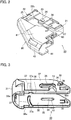
FIG. 3 is a perspective view of a lever of the lever-type connector according to the first embodiment; -
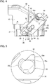
FIG. 4 is a side view of the male connector when a temporary setting is released; -
FIG. 5 is an enlarged view of a part Y inFIG. 4 ; -
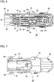
FIG. 6 is a bottom view of the male connector when the temporary setting is released; -
FIG. 7 is a plan view of the male connector when the temporary setting is released; -
FIG. 8 is a perspective view of a frame of a female connector of the lever-type connector according to the first embodiment; -
FIG. 9 is an enlarged side view around a cam groove of the frame; -
FIG. 10 is a cross-sectional view taken along a line X-X inFIG. 8 ; -
FIG. 11A is a perspective view of a grommet mounted on a flange of the frame as viewed from the front; -
FIG. 11B is a perspective view of a part Y inFIG. 11A as viewed from the rear; -
FIG. 12A is a perspective view of a sensing member used in the lever-type connector according to the first embodiment as viewed from the front; -
FIG. 12B is a perspective view of the sensing member as viewed from the rear; -
FIG. 13 is a side view illustrating a state before the temporary setting of the lever-type connector according to the first embodiment; -
FIG. 14A is a side view illustrating the lever-type connector in a temporary setting state at a start of lever pivot according to the first embodiment; -
FIG. 14B is a cross-sectional view taken along a line X-X inFIG. 14A ; -
FIG. 15A is a side view illustrating the lever-type connector in a state at completion of the lever pivot according to the first embodiment; -
FIG. 15B is a schematic cross-sectional view taken along a line X-X inFIG. 15A ; -
FIG. 16 is a side view illustrating a state in which sliding of the lever of the lever-type connector is completed according to the first embodiment; -
FIG. 17 is a side view illustrating a state in which the lever-type connector is passed through a mounting hole of a vehicle body panel according to the first embodiment; -
FIG. 18 is a perspective view illustrating the state in which the lever-type connector is passed through the mounting hole of the vehicle body panel according to the first embodiment; -
FIG. 19 is a side view illustrating a state in which a panel hooking portion of the lever-type connector is passed through the mounting hole of the vehicle body panel according to the first embodiment; -
FIG. 20 is a side view illustrating a state in which the panel hooking portion of the lever-type connector is hooked on an edge of the mounting hole of the vehicle body panel according to the first embodiment; -
FIG. 21 is a side view illustrating a state in which the lever-type connector is assembled to the vehicle body panel according to the first embodiment; -
FIG. 22 is a perspective view of a principle part of a female connector of a lever-type connector according to a second embodiment of the present invention as viewed from the rear; -
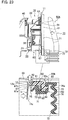
FIG. 23 is a side view illustrating a state in which a panel hooking portion of the lever-type connector is hooked on the edge of the mounting hole of the vehicle body panel according to the second embodiment; -
FIG. 24 is a side view illustrating a state in which the lever-type connector is assembled to the vehicle body panel according to the second embodiment; -
FIG. 25 is a cross-sectional view illustrating a state in which a connector housing of a connector with a grommet according to a comparative example is properly inserted into a mounting hole of the panel; and -
FIG. 26 is a partial cross-sectional view illustrating a state in which the connector housing of the connector with a grommet according to the comparative example is incompletely inserted into the mounting hole of the panel. - Hereinafter, an embodiment of the present invention will be described with reference to the drawings.
- A first embodiment of the present invention will be described with reference to
FIGS. 1 to 21 . - As illustrated in
FIGS. 1 and21 , the lever-type connector 10 includes amale connector 20 and a female connector (connector with a grommet) 50. Themale connector 20 is arranged on an inside of a vehicle body panel (panel) 11 (a side opposite to a door side). Thefemale connector 50 is arranged on an outside of the vehicle body panel 11 (door side). - As illustrated in
FIGS. 1 ,4 , and6 , themale connector 20 includes amale housing 21 made of a synthetic resin, alever 30 made of a synthetic resin and acable cover 40 made of a synthetic resin. Themale housing 21 houses a plurality of male terminals (terminals), not illustrated, and is fitted into and disengaged from afemale housing 51 of thefemale connector 50. Thelever 30 is pivotably supported and slidably supported by themale housing 21 viasupport shafts 24 and 24 (only onesupport shaft 24 is illustrated inFIGS. 1 and4 ). Thelever 30 fits and disengages themale housing 21 and thefemale housing 51 by a pivoting operation. Thecable cover 40 is mounted on themale housing 21 so as to cover a rear side of the male housing 21 (a side opposite to a side where themale connector 20 faces the female connector 50). - As illustrated in
FIGS. 1 ,2 , and6 , themale housing 21 includes ahousing body 22 having a rectangular block shape and ahood portion 23. Thehousing body 22 includes a plurality of terminal receivingholes 22a which receives male terminals. Thehood portion 23 is formed integrally on the front side of the housing body 22 (the side where themale connector 20 faces the female connector 50) so as to protrude therefrom. Ahousing body 52 of thefemale housing 51 is fitted into thehood portion 23. Thesupport shafts housing body 22 and thehood portion 23. Thesupport shafts lever 30. -
Guide projections male connector 20 faces the female connector 50) so as to protrude therefrom, and at a position near anoperation portion 31 of thelever 30, described later. As illustrated inFIG. 2 , temporary locking recesses (temporary locked portions) 26 and 26 and final locking recesses (final locked portions) 27 and 27 are respectively formed on thehood portion 23 and the side surfaces 22b and 22b on both sides of thehousing body 22, at positions corresponding to trajectories of the pivotal movements of projectingportions lever 30, described later (only onetemporary locking recess 26 and onefinal locking recess 27 are illustrated inFIG. 2 ). - As illustrated in
FIGS. 1 ,3 , and4 , thelever 30 is mounted on themale housing 21 so as to cover a part of themale housing 21 of themale connector 20 and a part of thecable cover 40. Thelever 30 pulls themale connector 20 and thefemale connector 50 toward each other by the pivoting operation from a lever pivot start position illustrated inFIG. 14A to a lever pivot completion position illustrated inFIG. 15A , to fit themale connector 20 and thefemale connector 50. Thelever 30 includes theoperation portion 31 and a pair ofarm portions operation portion 31. - As illustrated in
FIGS. 1 ,3 , and4 , a bearing hole (bearing portion) 33 is formed at a center of eacharm portion 32 of thelever 30. The bearinghole 33 includes ashaft sliding groove 34 in which thesupport shaft 24 slides. A column-shapedcam boss 35 is integrally formed so as to protrude from eacharm portion 32. - As illustrated in
FIGS. 4 to 7 andFIG. 14B , aprojection 36 having a taperedportion 36a is integrally formed on an outside of thecam boss 35 in the temporary setting release direction (direction of disengagement of the connector) R so as to protrude therefrom. When themale connector 20 and thefemale connector 50 are fitted, the taperedportion 36a obliquely opposes a surface of atemporary locking projection 65a of thecam groove 65, described later, on the side of the temporary setting release direction R. Further, as illustrated inFIGS. 5 and15B , aposition control rib 35b that engages with a draw-inrib 65b of thecam groove 65 is integrally formed so as to protrude from the upper end of ashaft portion 35a of thecam boss 35. - As illustrated in
FIG. 3 , an arc-shapedguide groove 37 with which theguide projection 25 engages, is formed between theoperation portion 31 and thebearing hole 33 in eacharm portion 32. Theguide groove 37 is formed in an elongated arc shape centering on thebearing hole 33. On the open-end side of theguide groove 37, apickup taper 37a for guiding theguide projection 25 is formed. - As illustrated in
FIG. 3 , eacharm portion 32 of thelever 30 is provided with a slidingportion 38 on which theguide projection 25 slides in the sliding direction after the pivot of thelever 30. The slidingportion 38 is formed in a rail shape with a concave inside. Further, eacharm portion 32 is provided with acontact part 38a with which theguide projection 25 contacts at the end of the slide after the pivot of thelever 30. Theguide projection 25 slides in theguide groove 37 by the pivoting operation of thelever 30, and after themale connector 20 and thefemale connector 50 are completely fitted, theguide projection 25 slides along the slidingportion 38 until theguide projection 25 butts thecontact part 38a. With such a configuration, thelever 30 can slide with respect to thehousing body 22 of themale housing 21, as illustrated inFIGS. 15A and16 . - As illustrated in
FIGS. 1 and3 , the locking arm (locking portion) 39 that is resiliently deformed in a direction perpendicular to the fitting direction of the housings, is formed on an outside of the distal end of eacharm portion 32 of thelever 30. The projectingportion 39a of the lockingarm 39 is locked in and released from thetemporary locking recess 26 or thefinal locking recess 27. With such a configuration, the lockingarm 39 serves to lock and release thelever 30 with respect to thetemporary locking recess 26 or thefinal locking recess 27. - As illustrated in
FIGS. 1 and2 , thecable cover 40 includes a pair ofside walls bent ceiling wall 42. As illustrated inFIG. 6 , when thecable cover 40 is slid and mounted on the rear end side of thehousing body 22 of the male housing 21 (an end on the side opposite to the side where themale connector 20 faces the female connector 50),lock portions 43 formed at the lower ends of theside walls portions 28 formed in thehousing body 22. - As illustrated in
FIGS. 1 and21 , thefemale connector 50 with a grommet includes thefemale housing 51, agrommet 70 made of rubber, and an indicator (sensing member) 80 made of a composite resin. Thefemale housing 51 includes a plurality ofterminal housing chambers 53 configured to house female terminals (terminals), not illustrated. Thefemale housing 51 includes ahousing body 52 made of a synthetic resin and acylindrical frame 60 made of a synthetic resin. Thehousing body 52 is fitted into and disengaged from themale housing 21 of themale connector 20. Theframe 60 is fitted on the outer circumference of thehousing body 52 to form an exterior and is locked in a mountinghole 12 of thevehicle body panel 11. Thegrommet 70 is mounted on aflange 62 of theframe 60. The sensingmember 80 is inserted into aninsertion hole 62a formed in theflange 62 and includes a part (sensing part 84) located outward than theinsertion hole 62a (a side where thegrommet 70 is located). Thesensing part 84 is received in a receivingpart 76 formed on apanel contact part 71. When a lockingprojection 67 is locked to thevehicle body panel 11, the sensingmember 80 is pushed out by thevehicle body panel 11 to move toward awall 76a of the receivingpart 76 outside theflange 62. Accordingly, the sensingmember 80 senses a locked state of the lockingprojection 67. - As illustrated in
FIG. 1 , thehousing body 52 includes the plurality ofterminal housing chambers 53 configured to house the female terminals and is formed into a rectangular block shape. At positions on both sides of thehousing body 52 facing the temporary locking recesses 26 and 26 formed on the side surfaces 22b and 22b on both sides of themale housing 21, release projections (release parts), not illustrated, configured to release a temporary locking state between the projectingportions arms lever 30 and the temporary locking recesses 26 and 26, are formed respectively. - As illustrated in
FIG. 8 , theframe 60 includes aframe body 61 having a cylindrical shape notched on an upper surface, and theflange 62 having an annular plate-shape. Theflange 62 is formed so as to integrally protrude outward from the entire circumference on one end of theframe body 61. Theflange 62 faces anedge 12a of the mountinghole 12 of thevehicle body panel 11 when thefemale connector 50 is mounted on thevehicle body panel 11. - A
panel hooking portion 63 which is hooked on theedge 12a and locked to theedge 12a of the mountinghole 12, is provided on an upper side of theframe body 61. By pivoting thefemale housing 51 with thepanel hooking portion 63 as a fulcrum in a state where thepanel hooking portion 63 is hooked on theedge 12a of the mountinghole 12, the lockingprojection 67, described later, can be locked in the mountinghole 12. - As illustrated in
FIGS. 1 and8 , alocking frame portion 64 is provided below thepanel hooking portion 63 of theframe body 61. The lockingframe portion 64 locks thehousing body 52 of thefemale housing 51 provided insideside walls frame body 61 with a gap. A pair of abuttingportions bottom wall 61b of theframe body 61. The abuttingportions vehicle body panel 11 when the lockingprojection 67, described later, is not properly locked in the mountinghole 12 of thevehicle body panel 11. Thehood portion 23 of thehousing body 22 of themale housing 21 is fitted between thehousing body 52 of thefemale housing 51 and thecylindrical frame body 61 of theframe 60. A pair of projectingportions flange 62 integrally with theflange 62 of theframe 60 at positions facing the abuttingportions flange 62. The projectingportions deep groove portion 74 formed at the back of aflange fitting groove 73 of thegrommet 70, described later, without penetration. - As illustrated in
FIGS. 8 and9 ,cam grooves cam bosses 35 of thelever 30 are engaged, are formed on the opposite sides of theflange 62 at the center of theside walls frame body 61, respectively. Eachcam groove 65 includes thetemporary locking projection 65a, the draw-inrib 65b, and a pushing-side sliding surface 65d. Thetemporary locking projection 65a is provided on thecam groove 65 side where an entrance is located. The draw-inrib 65b is formed with a drawn-inside sliding surface 65c extending in an L-shape from thetemporary locking projection 65a. The pushing-side sliding surface 65d faces the drawn-inside sliding surface 65c of the draw-inrib 65b. - As illustrated in
FIGS. 8 and10 , aflexible arm 66, which is resiliently deformed via a laterally elongatedslit 66a, is provided between the abuttingportions bottom wall 61b of theframe body 61. At a position near theflange 62 of theflexible arm 66, the lockingprojection 67 is formed on an outside of theflexible arm 66 so as to protrude outward (the side opposite to the side facing thebottom wall 61b). The lockingprojection 67 is locked to thevehicle body panel 11 by sandwiching thevehicle body panel 11 between the lockingprojection 67 and theflange 62 via awaterproof lip 75 of thegrommet 70, described later, as illustrated inFIG. 21 . The lockingprojection 67 includes a lockingsurface 67a locked to theedge 12a of the mountinghole 12 of thevehicle body panel 11, and an inclined surface (taper) 67b for guiding into the mountinghole 12. - As illustrated in
FIGS. 10 ,20 , and21 , an indicator (sensing member) 80 configured to sense whether or not the lockingprojection 67 is locked properly to thevehicle body panel 11, is provided between anindicator engagement portion 66b of theflexible arm 66 and the lockingsurface 67a of the lockingprojection 67. - As illustrated in
FIGS. 1 and11A , thegrommet 70 includes thepanel contact part 71 and acable receiving part 72. Thepanel contact part 71 is fitted into theflange 62 so as to cover theflange 62. Thepanel contact part 71 comes into tight contact with theedge 12a of the mountinghole 12 of thevehicle body panel 11 when thefemale connector 50 is mounted on thevehicle body panel 11. - As illustrated in
FIG. 11A , theflange fitting groove 73 is formed inside thepanel contact part 71. Theflange 62 is inserted into theflange fitting groove 73 over the entire circumference of theflange 62. Thedeep groove portion 74 is formed below theflange fitting groove 73. The projectingportions flange 62 are inserted into thedeep groove portion 74 without penetration. Thewaterproof lip 75 is integrally formed on an outside of thepanel contact part 71. When attaching thefemale connector 50 to thevehicle body panel 11, thewaterproof lip 75 is pressed against awall surface 11a around theedge 12a of the mountinghole 12 of thevehicle body panel 11 to come into tight contact with theedge 12a. - As illustrated in
FIGS. 11A and 11B , the receivingpart 76 configured to accommodate thesensing part 84 of the sensingmember 80 is integrally formed so as to protrude from abottom surface 71a to aback surface 71b of thepanel contact part 71. The receivingpart 76 communicates with the bag-shapeddeep groove portion 74. As illustrated inFIG. 20 , on an outer surface of thewall 76a of the receivingpart 76 on which aprojection 86 having a cylindrical shape used for sensing by the sensingmember 80 contacts, an annularconcave groove 76b having a diameter larger than a diameter of theprojection 86 is formed. With such a configuration, when thewall 76a of the receivingpart 76 is pushed outward in association with the movement of theprojection 86, thewall 76a in the annularconcave groove 76b bulges easily outward. - As illustrated in
FIGS. 12A and 12B , the sensingmember 80 includes acontact part 81 and thesensing part 84. Thecontact part 81 includes acontact surface 82 configured to come into contact with thewall surface 11a of thevehicle body panel 11 or the lockingsurface 67a of the lockingprojection 67, and a lockingsurface 83 that is to be locked to theflange 62. Thesensing part 84 is formed to be bent in an L-shape from thecontact part 81. Thesensing part 84 includes a lockingsurface 85 that is to be locked to theflange 62, and theprojection 86 having the column shape used for sensing by the sensingmember 80. Thesensing part 84 contacts thewall 76a of the receivingpart 76 of thegrommet 70. Abase portion 84a of thesensing part 84 is inserted into theinsertion hole 62a formed in theflange 62, and thesensing part 84 on a side where theprojection 86 is located, which is located outward than theinsertion hole 62a, is received in the receivingpart 76. As illustrated inFIGS. 20 and21 , the sensingmember 80 is configured to be movable between the lockingsurface 67a of the lockingprojection 67 that is locked to thevehicle body panel 11 and thewall 76a of the receivingpart 76. When the lockingprojection 67 is properly locked to thevehicle body panel 11, the sensingmember 80 is pushed out by thevehicle body panel 11 in the anti-locking direction F (the direction away from the vehicle body panel 11) by the thickness t of thevehicle body panel 11. - As described above, according to the lever-
type connector 10 of the first embodiment, before assembling the lever-type connector 10 to the mountinghole 12 of the vehicle body panel 11 (before temporary setting), the bearing holes 33 and 33 having theshaft sliding grooves lever 30 are assembled to thesupport shafts male housing 21 of themale connector 20, and the projectingportions arms lever 30 are temporarily locked to the temporary locking recesses 26 and 26 of themale housing 21 to maintain the temporary locking state of thelever 30 as illustrated inFIGS. 4 and13 (it is noted thatFIG. 13 illustrates one sides of themale connector 20 and the female connector 50). When thelever 30 is in the temporary locking state with respect to themale housing 21, thelever 30 is not allowed to pivot in the fitting direction between themale housing 21 and thefemale housing 51 of thefemale connector 50. - When the
housing body 52 of thefemale housing 51 is pushed into thehood portion 23 of themale housing 21 in the temporary locking state of thelever 30, the release projections, not illustrated, of thehousing body 52 cause the lockingarms lever 30 to be resiliently deformed outward. Accordingly, the temporary locking state of the temporary locking recesses 26 and 26 of themale housing 21 and the projectingportions arms lever 30 is released, and thelever 30 is allowed to pivot in the fitting direction between themale housing 21 and thefemale housing 51. - Next, as illustrated in
FIG. 14A (it is noted thatFIG. 14A illustrates one sides of themale connector 20 and the female connector 50), themale housing 21 and thefemale housing 51 are made face each other, and thecam bosses lever 30 are inserted into thecam grooves frame 60 of thefemale connector 50 to be locked to thetemporary locking projections cam grooves male housing 21 of themale connector 20 and thefemale housing 51 of thefemale connector 50 are brought into a temporary setting state by locking thecam bosses lever 30 to thetemporary locking projections cam grooves male housing 21 is pulled out from the female housing 51 (pulled out in the temporary setting release direction R illustrated inFIG. 4 ), and thetapered portions projections cam bosses temporary locking projections cam grooves male connector 20 is smoothly disengaged from thefemale connector 50. - Next, as illustrated in
FIG. 15A (it is noted thatFIG. 15A illustrates one sides of themale connector 20 and the female connector 50), thelever 30 is pivoted around thesupport shafts male housing 21 as a pivotal axis, and theshaft portions cam bosses side sliding surfaces cam grooves female housing 51 is drawn inward. When thefemale housing 51 is drawn inward, theposition control ribs cam bosses ribs cam grooves shaft portions cam bosses side sliding surfaces cam grooves - At this time, the
lever 30 pivots by the movement of theguide projections male housing 21 along the arc-shapedguide grooves lever 30 while thesupport shafts male housing 21 are in sliding contact with the bearing holes 33 and 33 of thelever 30. - Next, as illustrated in
FIG. 15A , when the pivot of thelever 30 is completed, thelever 30 is allowed to slide with respect to themale housing 21. That is, when the pivot of thelever 30 ends, theguide projections male housing 21 come off the pickup tapers 37a and 37a formed at the open ends of the arc-shapedguide grooves lever 30, so that thelever 30 is allowed to slide with respect to themale housing 21. - Then, as illustrated in
FIG. 16 (it is noted thatFIG. 16 illustrates one sides of themale connector 20 and the female connector 50), by pushing theoperation portion 31 of thelever 30, thelever 30 is slid along theguide projections male housing 21, and the projectingportions arms lever 30 are locked to the final locking recesses 27 and 27 of themale housing 21. In this case, thelever 30 is brought into a final locked state with respect to themale housing 21. When thelever 30 slides, thesupport shafts male housing 21 slide on theshaft sliding grooves lever 30. By inserting thelever 30 into theframe 60 of thefemale housing 51 by sliding thelever 30, the fitting between themale housing 21 and thefemale housing 51 is completed. - Next, a procedure for assembling the lever-
type connector 10 in which themale connector 20 is fitted into thefemale connector 50 into the mountinghole 12 of thevehicle body panel 11 will be described with reference toFIGS. 17 to 21 . - As illustrated in
FIGS. 17 and 18 , themale connector 20 fitted into thefemale connector 50 is passed through the mountinghole 12 of thevehicle body panel 11 from the side where the door panel is located. - Next, as illustrated in
FIG. 19 , thepanel hooking portion 63 of theframe 60 of thefemale connector 50 starts to be inserted into the mountinghole 12 of thevehicle body panel 11. - As illustrated in
FIG. 20 , by further inserting thepanel hooking portion 63 of theframe 60 into the mountinghole 12 of thevehicle body panel 11, thepanel hooking portion 63 is locked to theedge 12a in a state in which thepanel hooking portion 63 is hooked on theedge 12a of the mountinghole 12. In a state in which thepanel hooking portion 63 is not hooked on theedge 12a of the mountinghole 12, the abuttingportions frame 60 come into contact with thewall surface 11a of thevehicle body panel 11, so that the lockingprojection 67 of theframe 60 is not locked to theedge 12a of the mountinghole 12 of thevehicle body panel 11. - Then, by making the
female housing 51 pivot about thepanel hooking portion 63 as a fulcrum in a state in which thepanel hooking portion 63 of theframe 60 is hooked on theedge 12a of the mountinghole 12 of thevehicle body panel 11 as illustrated inFIGS. 20 and21 , theinclined surface 67b of the lockingprojection 67 of theframe 60 comes into contact with theedge 12a of the mountinghole 12, and theflexible arm 66 provided with the lockingprojection 67 is vertically flexed, so that the lockingprojection 67 of theframe 60 is locked in the mountinghole 12 of thevehicle body panel 11. At this time, thewaterproof lip 75 of thegrommet 70 is pressed against thewall surface 11a of thevehicle body panel 11 without any gap, so that water can be prevented from entering through the mountinghole 12 of thevehicle body panel 11. - As illustrated in
FIG. 21 , in the locking completed state in which the lockingprojection 67 of theframe 60 is properly locked in the mountinghole 12 of thevehicle body panel 11, the sensingmember 80 moves rearward by thewall surface 11a of thevehicle body panel 11 pushing acontact surface 82 of thecontact part 81 of the sensingmember 80 simultaneously with the locking of the lockingprojection 67. In association with the movement of the sensingmember 80, theprojection 86 of thesensing part 84 of the sensingmember 80 pushes out thewall 76a of the receivingpart 76 of thegrommet 70 to make thewall 76a bulge to complete the locking of the lockingprojection 67. - In other words, when the locking
projection 67 is properly locked to thevehicle body panel 11, the sensingmember 80 is pushed out by thevehicle body panel 11 in the anti-locking direction F by the thickness t of thevehicle body panel 11, and theprojection 86 make thewall 76a of the receivingpart 76 bulge outward. Accordingly, a bulgingportion 76c of thewall 76a contacts theridge 77 of the bellows of thecable receiving part 72 without any gap. - On the other hand, as illustrated in
FIG. 20 , before the lockingprojections 67 is completely locked, a gap exists between thewall 76a of the receivingpart 76 and theridge 77 of the bellows of thecable receiving part 72. As described above, the difference in the state of thewall 76a is clear before and after the lockingprojection 67 is locked in the mountinghole 12 of thevehicle body panel 11, and good visibility is provided. Therefore, the operator can visually confirm the locking completed state of the lockingprojection 67 easily and reliably. Further, in order to ensure the visibility, only the sliding force for pushing out the sensingmember 80 is required, and no large load is generated. For this reason, the length adjustment of theflexible arm 66 becomes unnecessary, and it is possible to avoid an increase in the assembling force to thevehicle body panel 11. - As illustrated in
FIG. 21 , theprojection 86 of thesensing part 84 of the sensingmember 80 is received in thewall 76a of the receivingpart 76 of thegrommet 70 without penetration, so that deterioration of waterproof performance of thegrommet 70 is avoided. - Next, a second embodiment of the present invention will be described with reference to
FIGS. 22 to 24 . - As illustrated in
FIG. 22 , the second embodiment is different from the first embodiment in that thewall 76a of the receivingpart 76 that receives thesensing part 84 of the sensingmember 80 of thegrommet 70 is provided with asensing hole 76d having a circular shape where theprojection 86 of thesensing part 84 is inserted, in thefemale connector 50A with a grommet. Since the other configuration is the same as that of the first embodiment, the same components are denoted by the same reference numerals, and detailed description is omitted. - As illustrated in
FIG. 24 , when the lockingprojection 67 is properly locked to thevehicle body panel 11, the sensingmember 80 is pushed out by thevehicle body panel 11 in the anti-locking direction F by the thickness t of thevehicle body panel 11. Accordingly, theprojection 86 of the sensingmember 80 protrudes outward from thesensing hole 76d of thewall 76a of the receivingpart 76 by a thickness t of thevehicle body panel 11. - On the other hand, as illustrated in
FIG. 23 , before the lockingprojection 67 is completely locked, theprojection 86 does not protrude outward from thesensing hole 76d of thewall 76a of the receivingpart 76. As described above, the difference in the state of thesensing hole 76d is clear before and after the lockingprojection 67 is locked in the mountinghole 12 of thevehicle body panel 11, and good visibility is provided. Therefore, the operator can visually confirm the locking completed state of the lockingprojection 67 easily and reliably. Further, since a large force is not required for pushing out the sensingmember 80, that is, since only the force for sliding theprojection 86 of the sensingmember 80 in thesensing hole 76d of thewall 76a of the receivingpart 76 is necessary, a large load is not generated, and thus the mounting force required when locking the lockingprojection 67 to thevehicle body panel 11, is little affected. Furthermore, since thesensing hole 76d provided in thewall 76a of the receivingpart 76 is tightly closed by thesensing projection 86 of the sensingmember 80, the waterproofness is sufficiently ensured. - Next, a comparative example will be described.
- A connector 1 with a grommet according to the comparative example includes a
connector housing 2 and agrommet 7 configured to cover an outer circumference of theconnector housing 2 as illustrated inFIGS. 25 and 26 . Theconnector housing 2 is mounted in a mountinghole 9a of a vehicle body panel (panel) 9 via a lock projection 6 (locking projection) thereof in a state in which theconnector housing 2 is fitted into amating connector housing 8. Thegrommet 7 includes a mountingportion 7a. The distal end portion of aflange part 3 of theconnector housing 2 is fitted into afitting groove 7b of the mountingportion 7a. - The
flange part 3 includes asensing piece 4 protruding in a front-rear direction via afulcrum part 5. Thesensing piece 4 includes aninterference part 4a on the front side of thesensing piece 4 and includes aprotruding part 4b on the rear side of thesensing piece 4. Theinterference part 4a includes a claw-shapedlock projection 6 protruding outward at the front end of theinterference part 4a. Theprotruding part 4b presses athin part 7c of thegrommet 7 when thelock projection 6 is located in the mountinghole 9a. - As illustrated in
FIG. 26 , when theconnector housing 2 is placed in an incompletely inserted state in the mountinghole 9a of thepanel 9, that is, when thesensing piece 4 is still in a tilted state, and thelock projection 6 is in the mountinghole 9a, the protrudingpart 4b of thesensing piece 4 presses thethin part 7c of thegrommet 7, and thethin part 7c of thegrommet 7 bulges. - However, in the connector 1 with a grommet, when the
connector housing 2 is placed in the incompletely inserted state in the mountinghole 9a of thepanel 9, thesensing piece 4 in the tilted state is covered with thethin part 7c of thegrommet 7. Therefore, it is difficult for an operator to visually confirm the state in which thethin part 7c of thegrommet 7 is bulged. - As described above, in the connector 1 with a grommet, since the visibility of the
sensing piece 4 is poor, the operator must touch thegrommet 7 with the hand to confirm the bulging of thethin part 7c. In the case of a narrow work space, it is also difficult for an operator to touch thegrommet 7 with the hand to confirm the bulging of thethin part 7c. - Note that according to the present embodiment, the lever-type connector is assembled to the vehicle body panel after the fitting between the male connector and the female connector. However, the present invention is not limited thereto. For example, the male connector may be fitted into the female connector after assembling the female connector to the vehicle body panel.
- According to the respective embodiments, the female connector is constituted by the female housing and the frame, and the cam groove is provided on the frame. However, the present invention is not limited thereto. For example, the female connector may be constituted only by the female housing, and the female housing may be provided with a cam groove.
- Although the present invention has been described above by reference to the embodiment, the present invention is not limited to those and the configuration of parts can be replaced with any configuration having a similar function, as long as they lie within the scope of the claims.
Claims (5)
- A connector with a grommet comprising:a housing including a panel hooking portion that is hooked on an edge of a mounting hole of a panel and is locked to the edge, an annular flange that faces the edge, and a locking projection that is locked to the panel by sandwiching the panel between the locking projection and the flange, wherein the panel hooking portion, the flange, and the locking projection are formed on an outside of the housing;a grommet including a panel contact part that is fitted into the flange so as to cover the flange and comes into tight contact with the edge; anda sensing member inserted into an insertion hole formed in the flange and including a part located outward than the insertion hole,the part of the sensing member being received in a receiving part formed on the panel contact part,the sensing member being pushed out by the panel to move to an outside of the flange when the locking projection is locked to the panel, to sense a locked state of the locking projection, whereinthe housing is provided with a flexible arm which is resiliently deformable,the flexible arm is provided with the locking projection,the sensing member moves between a locking surface of the locking projection to be locked to the panel and a wall of the receiving part, andwhen the locking projection is locked to the panel, the sensing member is pushed out by the panel in an anti-locking direction by a thickness of the panel.
- The connector with a grommet according to claim 1, wherein when the locking projection is locked to the panel, (i) the sensing member is pushed out by the panel in the anti-locking direction by the thickness of the panel, (ii) a projection for sensing of the sensing member makes the wall of the receiving part bulge outward, and (iii) a bulging portion of the wall comes into contact with a ridge of bellows of a cable receiving part of the grommet without a gap.
- The connector with a grommet according to claim 1, wherein when the locking projection is locked to the panel, the sensing member is pushed out by the panel in the anti-locking direction by the thickness of the panel, and a projection for sensing of the sensing member protrudes outward from a sensing hole formed in the wall of the receiving part.
- The connector with a grommet according to claim 1, wherein the sensing member includesa contact part including a contact surface that comes into contact with a wall surface of the panel or the locking surface of the locking projection and a first locking surface that is to be locked to the flange, anda sensing part including a second locking surface that is to be locked to the flange and a projection for sensing of the sensing member, and configured to come into contact with the wall of the receiving part.
- The connector with a grommet according to claim 2 or 3, wherein the sensing member includesa contact part including a contact surface that comes into contact with a wall surface of the panel or the locking surface of the locking projection and a first locking surface that is to be locked to the flange, anda sensing part including a second locking surface that is to be locked to the flange and the projection for sensing, and configured to come into contact with the wall of the receiving part.
Applications Claiming Priority (1)
| Application Number | Priority Date | Filing Date | Title |
|---|---|---|---|
| JP2019079210A JP7032351B2 (en) | 2019-04-18 | 2019-04-18 | Connector with grommet |
Publications (2)
| Publication Number | Publication Date |
|---|---|
| EP3726670A1 EP3726670A1 (en) | 2020-10-21 |
| EP3726670B1 true EP3726670B1 (en) | 2021-06-09 |
Family
ID=70292808
Family Applications (1)
| Application Number | Title | Priority Date | Filing Date |
|---|---|---|---|
| EP20169759.6A Active EP3726670B1 (en) | 2019-04-18 | 2020-04-16 | Connector with grommet |
Country Status (4)
| Country | Link |
|---|---|
| US (1) | US11211752B2 (en) |
| EP (1) | EP3726670B1 (en) |
| JP (1) | JP7032351B2 (en) |
| CN (1) | CN111834836B (en) |
Families Citing this family (6)
| Publication number | Priority date | Publication date | Assignee | Title |
|---|---|---|---|---|
| JP6959294B2 (en) * | 2019-04-18 | 2021-11-02 | 矢崎総業株式会社 | Connector with grommet |
| USD939444S1 (en) * | 2019-06-20 | 2021-12-28 | Sumitomo Wiring Systems, Ltd. | Electrical connector |
| JP1658716S (en) * | 2019-06-20 | 2020-04-27 | ||
| JP1658718S (en) | 2019-06-20 | 2020-04-27 | ||
| CN113745910A (en) * | 2021-08-11 | 2021-12-03 | 重庆长安汽车股份有限公司 | Fakra integrated hybrid connector and vehicle |
| JP7509104B2 (en) * | 2021-09-17 | 2024-07-02 | 住友電装株式会社 | Covered connector, electronic unit, and connector unit |
Family Cites Families (24)
| Publication number | Priority date | Publication date | Assignee | Title |
|---|---|---|---|---|
| JPH0754932Y2 (en) * | 1990-07-09 | 1995-12-18 | 矢崎総業株式会社 | Waterproof structure of screw tightened connector |
| JP3075445B2 (en) * | 1992-11-04 | 2000-08-14 | 矢崎総業株式会社 | Mounting method and mounting structure of connector to panel |
| US5586909A (en) * | 1993-11-25 | 1996-12-24 | Sumitomo Wiring Systems, Ltd. | Sealing structure for a panel-mounted electrical connector |
| US5775944A (en) * | 1996-08-19 | 1998-07-07 | General Motors Corporation | Sealed connector-to-body interface |
| US5971791A (en) * | 1996-08-30 | 1999-10-26 | Kansei Corporation | Waterproof connector |
| JP3278048B2 (en) * | 1997-10-01 | 2002-04-30 | 住友電装株式会社 | connector |
| JP3863739B2 (en) * | 2001-07-16 | 2006-12-27 | 矢崎総業株式会社 | Waterproof low insertion force connector |
| JP3991670B2 (en) * | 2001-12-06 | 2007-10-17 | 住友電装株式会社 | connector |
| US6860759B2 (en) * | 2001-12-17 | 2005-03-01 | Sumitomo Wiring Systems, Ltd. | Connector and method of mounting a connector housing on a panel |
| JP3846628B2 (en) * | 2002-02-20 | 2006-11-15 | 住友電装株式会社 | connector |
| JP2003346990A (en) * | 2002-05-30 | 2003-12-05 | Sumitomo Wiring Syst Ltd | Panel attachment part |
| JP4791014B2 (en) * | 2004-09-06 | 2011-10-12 | 矢崎総業株式会社 | Waterproof connector |
| US7150640B2 (en) * | 2005-04-08 | 2006-12-19 | Yazaki Corporation | Lever type connector |
| JP4517940B2 (en) * | 2005-05-27 | 2010-08-04 | 住友電装株式会社 | connector |
| JP4559369B2 (en) * | 2006-02-03 | 2010-10-06 | 矢崎総業株式会社 | Packing mounting structure |
| JP4697061B2 (en) * | 2006-06-15 | 2011-06-08 | 住友電装株式会社 | connector |
| JP5806523B2 (en) * | 2011-06-24 | 2015-11-10 | 矢崎総業株式会社 | Grommet connector |
| JP2015207448A (en) * | 2014-04-21 | 2015-11-19 | 住友電装株式会社 | connector |
| JP6108236B2 (en) * | 2014-05-23 | 2017-04-05 | 住友電装株式会社 | connector |
| JP6454287B2 (en) | 2016-01-08 | 2019-01-16 | 矢崎総業株式会社 | Connector with grommet and connector |
| US10913407B2 (en) * | 2017-02-07 | 2021-02-09 | Ford Global Technologies, Llc | Grommet with tie-strap tower |
| JP6908427B2 (en) | 2017-04-25 | 2021-07-28 | 矢崎総業株式会社 | Grommets and wire harnesses |
| IT201800002675A1 (en) * | 2018-02-14 | 2019-08-14 | Tyco Electronics Amp Italia Srl | Electrical connection device |
| JP6970064B2 (en) * | 2018-08-30 | 2021-11-24 | 矢崎総業株式会社 | Grommet |
-
2019
- 2019-04-18 JP JP2019079210A patent/JP7032351B2/en active Active
-
2020
- 2020-04-14 CN CN202010290102.7A patent/CN111834836B/en active Active
- 2020-04-16 EP EP20169759.6A patent/EP3726670B1/en active Active
- 2020-04-16 US US16/850,394 patent/US11211752B2/en active Active
Also Published As
| Publication number | Publication date |
|---|---|
| JP2020177809A (en) | 2020-10-29 |
| JP7032351B2 (en) | 2022-03-08 |
| EP3726670A1 (en) | 2020-10-21 |
| US20200335919A1 (en) | 2020-10-22 |
| CN111834836B (en) | 2022-02-01 |
| US11211752B2 (en) | 2021-12-28 |
| CN111834836A (en) | 2020-10-27 |
Similar Documents
| Publication | Publication Date | Title |
|---|---|---|
| EP3726670B1 (en) | Connector with grommet | |
| US6935887B2 (en) | Connector preventive of incomplete fitting | |
| EP3955395B1 (en) | Connector assembly with sealed symmetrical split lever | |
| JP3667652B2 (en) | connector | |
| JP5029872B2 (en) | Lever type connector | |
| JP6539634B2 (en) | connector | |
| EP1056163B1 (en) | Electrical connector with keying means | |
| EP3725595A1 (en) | Grommet-equipped connector | |
| EP3744573B1 (en) | Connector with grommet | |
| JP2001118636A (en) | Connector | |
| JP3856768B2 (en) | connector | |
| US11482811B2 (en) | Lever-type connector | |
| EP3726669A1 (en) | Connector | |
| EP3726663A1 (en) | Grommet-equipped connector | |
| JP2000012148A (en) | Water-proof connector | |
| CN112688105B (en) | Connector with a locking member | |
| EP3726665A1 (en) | Lever-type connector | |
| CN111834796A (en) | Connector | |
| JP2009087866A (en) | connector | |
| JP4089172B2 (en) | connector |
Legal Events
| Date | Code | Title | Description |
|---|---|---|---|
| PUAI | Public reference made under article 153(3) epc to a published international application that has entered the european phase |
Free format text: ORIGINAL CODE: 0009012 |
|
| STAA | Information on the status of an ep patent application or granted ep patent |
Free format text: STATUS: REQUEST FOR EXAMINATION WAS MADE |
|
| 17P | Request for examination filed |
Effective date: 20200416 |
|
| AK | Designated contracting states |
Kind code of ref document: A1 Designated state(s): AL AT BE BG CH CY CZ DE DK EE ES FI FR GB GR HR HU IE IS IT LI LT LU LV MC MK MT NL NO PL PT RO RS SE SI SK SM TR |
|
| AX | Request for extension of the european patent |
Extension state: BA ME |
|
| RBV | Designated contracting states (corrected) |
Designated state(s): AL AT BE BG CH CY CZ DE DK EE ES FI FR GB GR HR HU IE IS IT LI LT LU LV MC MK MT NL NO PL PT RO RS SE SI SK SM TR |
|
| GRAP | Despatch of communication of intention to grant a patent |
Free format text: ORIGINAL CODE: EPIDOSNIGR1 |
|
| STAA | Information on the status of an ep patent application or granted ep patent |
Free format text: STATUS: GRANT OF PATENT IS INTENDED |
|
| INTG | Intention to grant announced |
Effective date: 20210322 |
|
| GRAS | Grant fee paid |
Free format text: ORIGINAL CODE: EPIDOSNIGR3 |
|
| GRAA | (expected) grant |
Free format text: ORIGINAL CODE: 0009210 |
|
| STAA | Information on the status of an ep patent application or granted ep patent |
Free format text: STATUS: THE PATENT HAS BEEN GRANTED |
|
| AK | Designated contracting states |
Kind code of ref document: B1 Designated state(s): AL AT BE BG CH CY CZ DE DK EE ES FI FR GB GR HR HU IE IS IT LI LT LU LV MC MK MT NL NO PL PT RO RS SE SI SK SM TR |
|
| REG | Reference to a national code |
Ref country code: GB Ref legal event code: FG4D |
|
| REG | Reference to a national code |
Ref country code: CH Ref legal event code: EP Ref country code: AT Ref legal event code: REF Ref document number: 1401255 Country of ref document: AT Kind code of ref document: T Effective date: 20210615 |
|
| REG | Reference to a national code |
Ref country code: DE Ref legal event code: R096 Ref document number: 602020000142 Country of ref document: DE |
|
| REG | Reference to a national code |
Ref country code: IE Ref legal event code: FG4D |
|
| REG | Reference to a national code |
Ref country code: LT Ref legal event code: MG9D |
|
| PG25 | Lapsed in a contracting state [announced via postgrant information from national office to epo] |
Ref country code: BG Free format text: LAPSE BECAUSE OF FAILURE TO SUBMIT A TRANSLATION OF THE DESCRIPTION OR TO PAY THE FEE WITHIN THE PRESCRIBED TIME-LIMIT Effective date: 20210909 Ref country code: FI Free format text: LAPSE BECAUSE OF FAILURE TO SUBMIT A TRANSLATION OF THE DESCRIPTION OR TO PAY THE FEE WITHIN THE PRESCRIBED TIME-LIMIT Effective date: 20210609 Ref country code: HR Free format text: LAPSE BECAUSE OF FAILURE TO SUBMIT A TRANSLATION OF THE DESCRIPTION OR TO PAY THE FEE WITHIN THE PRESCRIBED TIME-LIMIT Effective date: 20210609 Ref country code: LT Free format text: LAPSE BECAUSE OF FAILURE TO SUBMIT A TRANSLATION OF THE DESCRIPTION OR TO PAY THE FEE WITHIN THE PRESCRIBED TIME-LIMIT Effective date: 20210609 |
|
| REG | Reference to a national code |
Ref country code: AT Ref legal event code: MK05 Ref document number: 1401255 Country of ref document: AT Kind code of ref document: T Effective date: 20210609 |
|
| REG | Reference to a national code |
Ref country code: NL Ref legal event code: MP Effective date: 20210609 |
|
| PG25 | Lapsed in a contracting state [announced via postgrant information from national office to epo] |
Ref country code: SE Free format text: LAPSE BECAUSE OF FAILURE TO SUBMIT A TRANSLATION OF THE DESCRIPTION OR TO PAY THE FEE WITHIN THE PRESCRIBED TIME-LIMIT Effective date: 20210609 Ref country code: RS Free format text: LAPSE BECAUSE OF FAILURE TO SUBMIT A TRANSLATION OF THE DESCRIPTION OR TO PAY THE FEE WITHIN THE PRESCRIBED TIME-LIMIT Effective date: 20210609 Ref country code: LV Free format text: LAPSE BECAUSE OF FAILURE TO SUBMIT A TRANSLATION OF THE DESCRIPTION OR TO PAY THE FEE WITHIN THE PRESCRIBED TIME-LIMIT Effective date: 20210609 Ref country code: NO Free format text: LAPSE BECAUSE OF FAILURE TO SUBMIT A TRANSLATION OF THE DESCRIPTION OR TO PAY THE FEE WITHIN THE PRESCRIBED TIME-LIMIT Effective date: 20210909 Ref country code: GR Free format text: LAPSE BECAUSE OF FAILURE TO SUBMIT A TRANSLATION OF THE DESCRIPTION OR TO PAY THE FEE WITHIN THE PRESCRIBED TIME-LIMIT Effective date: 20210910 |
|
| PG25 | Lapsed in a contracting state [announced via postgrant information from national office to epo] |
Ref country code: CZ Free format text: LAPSE BECAUSE OF FAILURE TO SUBMIT A TRANSLATION OF THE DESCRIPTION OR TO PAY THE FEE WITHIN THE PRESCRIBED TIME-LIMIT Effective date: 20210609 Ref country code: AT Free format text: LAPSE BECAUSE OF FAILURE TO SUBMIT A TRANSLATION OF THE DESCRIPTION OR TO PAY THE FEE WITHIN THE PRESCRIBED TIME-LIMIT Effective date: 20210609 Ref country code: SM Free format text: LAPSE BECAUSE OF FAILURE TO SUBMIT A TRANSLATION OF THE DESCRIPTION OR TO PAY THE FEE WITHIN THE PRESCRIBED TIME-LIMIT Effective date: 20210609 Ref country code: PT Free format text: LAPSE BECAUSE OF FAILURE TO SUBMIT A TRANSLATION OF THE DESCRIPTION OR TO PAY THE FEE WITHIN THE PRESCRIBED TIME-LIMIT Effective date: 20211011 Ref country code: NL Free format text: LAPSE BECAUSE OF FAILURE TO SUBMIT A TRANSLATION OF THE DESCRIPTION OR TO PAY THE FEE WITHIN THE PRESCRIBED TIME-LIMIT Effective date: 20210609 Ref country code: RO Free format text: LAPSE BECAUSE OF FAILURE TO SUBMIT A TRANSLATION OF THE DESCRIPTION OR TO PAY THE FEE WITHIN THE PRESCRIBED TIME-LIMIT Effective date: 20210609 Ref country code: SK Free format text: LAPSE BECAUSE OF FAILURE TO SUBMIT A TRANSLATION OF THE DESCRIPTION OR TO PAY THE FEE WITHIN THE PRESCRIBED TIME-LIMIT Effective date: 20210609 Ref country code: ES Free format text: LAPSE BECAUSE OF FAILURE TO SUBMIT A TRANSLATION OF THE DESCRIPTION OR TO PAY THE FEE WITHIN THE PRESCRIBED TIME-LIMIT Effective date: 20210609 Ref country code: EE Free format text: LAPSE BECAUSE OF FAILURE TO SUBMIT A TRANSLATION OF THE DESCRIPTION OR TO PAY THE FEE WITHIN THE PRESCRIBED TIME-LIMIT Effective date: 20210609 |
|
| PG25 | Lapsed in a contracting state [announced via postgrant information from national office to epo] |
Ref country code: PL Free format text: LAPSE BECAUSE OF FAILURE TO SUBMIT A TRANSLATION OF THE DESCRIPTION OR TO PAY THE FEE WITHIN THE PRESCRIBED TIME-LIMIT Effective date: 20210609 |
|
| REG | Reference to a national code |
Ref country code: DE Ref legal event code: R097 Ref document number: 602020000142 Country of ref document: DE |
|
| PLBE | No opposition filed within time limit |
Free format text: ORIGINAL CODE: 0009261 |
|
| STAA | Information on the status of an ep patent application or granted ep patent |
Free format text: STATUS: NO OPPOSITION FILED WITHIN TIME LIMIT |
|
| PG25 | Lapsed in a contracting state [announced via postgrant information from national office to epo] |
Ref country code: DK Free format text: LAPSE BECAUSE OF FAILURE TO SUBMIT A TRANSLATION OF THE DESCRIPTION OR TO PAY THE FEE WITHIN THE PRESCRIBED TIME-LIMIT Effective date: 20210609 |
|
| 26N | No opposition filed |
Effective date: 20220310 |
|
| PG25 | Lapsed in a contracting state [announced via postgrant information from national office to epo] |
Ref country code: AL Free format text: LAPSE BECAUSE OF FAILURE TO SUBMIT A TRANSLATION OF THE DESCRIPTION OR TO PAY THE FEE WITHIN THE PRESCRIBED TIME-LIMIT Effective date: 20210609 |
|
| PG25 | Lapsed in a contracting state [announced via postgrant information from national office to epo] |
Ref country code: IT Free format text: LAPSE BECAUSE OF FAILURE TO SUBMIT A TRANSLATION OF THE DESCRIPTION OR TO PAY THE FEE WITHIN THE PRESCRIBED TIME-LIMIT Effective date: 20210609 |
|
| REG | Reference to a national code |
Ref country code: BE Ref legal event code: MM Effective date: 20220430 |
|
| PG25 | Lapsed in a contracting state [announced via postgrant information from national office to epo] |
Ref country code: MC Free format text: LAPSE BECAUSE OF FAILURE TO SUBMIT A TRANSLATION OF THE DESCRIPTION OR TO PAY THE FEE WITHIN THE PRESCRIBED TIME-LIMIT Effective date: 20210609 Ref country code: LU Free format text: LAPSE BECAUSE OF NON-PAYMENT OF DUE FEES Effective date: 20220416 Ref country code: FR Free format text: LAPSE BECAUSE OF NON-PAYMENT OF DUE FEES Effective date: 20220430 |
|
| PG25 | Lapsed in a contracting state [announced via postgrant information from national office to epo] |
Ref country code: BE Free format text: LAPSE BECAUSE OF NON-PAYMENT OF DUE FEES Effective date: 20220430 |
|
| PG25 | Lapsed in a contracting state [announced via postgrant information from national office to epo] |
Ref country code: IE Free format text: LAPSE BECAUSE OF NON-PAYMENT OF DUE FEES Effective date: 20220416 |
|
| REG | Reference to a national code |
Ref country code: CH Ref legal event code: PL |
|
| PG25 | Lapsed in a contracting state [announced via postgrant information from national office to epo] |
Ref country code: LI Free format text: LAPSE BECAUSE OF NON-PAYMENT OF DUE FEES Effective date: 20230430 Ref country code: CH Free format text: LAPSE BECAUSE OF NON-PAYMENT OF DUE FEES Effective date: 20230430 |
|
| PG25 | Lapsed in a contracting state [announced via postgrant information from national office to epo] |
Ref country code: MK Free format text: LAPSE BECAUSE OF FAILURE TO SUBMIT A TRANSLATION OF THE DESCRIPTION OR TO PAY THE FEE WITHIN THE PRESCRIBED TIME-LIMIT Effective date: 20210609 Ref country code: CY Free format text: LAPSE BECAUSE OF FAILURE TO SUBMIT A TRANSLATION OF THE DESCRIPTION OR TO PAY THE FEE WITHIN THE PRESCRIBED TIME-LIMIT Effective date: 20210609 |
|
| PG25 | Lapsed in a contracting state [announced via postgrant information from national office to epo] |
Ref country code: HU Free format text: LAPSE BECAUSE OF FAILURE TO SUBMIT A TRANSLATION OF THE DESCRIPTION OR TO PAY THE FEE WITHIN THE PRESCRIBED TIME-LIMIT; INVALID AB INITIO Effective date: 20200416 |
|
| PG25 | Lapsed in a contracting state [announced via postgrant information from national office to epo] |
Ref country code: MT Free format text: LAPSE BECAUSE OF FAILURE TO SUBMIT A TRANSLATION OF THE DESCRIPTION OR TO PAY THE FEE WITHIN THE PRESCRIBED TIME-LIMIT Effective date: 20210609 |
|
| GBPC | Gb: european patent ceased through non-payment of renewal fee |
Effective date: 20240416 |
|
| PG25 | Lapsed in a contracting state [announced via postgrant information from national office to epo] |
Ref country code: GB Free format text: LAPSE BECAUSE OF NON-PAYMENT OF DUE FEES Effective date: 20240416 |
|
| PG25 | Lapsed in a contracting state [announced via postgrant information from national office to epo] |
Ref country code: GB Free format text: LAPSE BECAUSE OF NON-PAYMENT OF DUE FEES Effective date: 20240416 |
|
| PGFP | Annual fee paid to national office [announced via postgrant information from national office to epo] |
Ref country code: DE Payment date: 20250305 Year of fee payment: 6 |
|
| PG25 | Lapsed in a contracting state [announced via postgrant information from national office to epo] |
Ref country code: TR Free format text: LAPSE BECAUSE OF FAILURE TO SUBMIT A TRANSLATION OF THE DESCRIPTION OR TO PAY THE FEE WITHIN THE PRESCRIBED TIME-LIMIT Effective date: 20210609 |