EP3726664A1 - Rotary connector - Google Patents
Rotary connector Download PDFInfo
- Publication number
- EP3726664A1 EP3726664A1 EP20168195.4A EP20168195A EP3726664A1 EP 3726664 A1 EP3726664 A1 EP 3726664A1 EP 20168195 A EP20168195 A EP 20168195A EP 3726664 A1 EP3726664 A1 EP 3726664A1
- Authority
- EP
- European Patent Office
- Prior art keywords
- housing
- assurance
- locked
- bayonet ring
- connector
- Prior art date
- Legal status (The legal status is an assumption and is not a legal conclusion. Google has not performed a legal analysis and makes no representation as to the accuracy of the status listed.)
- Granted
Links
Images





Classifications
-
- H—ELECTRICITY
- H01—ELECTRIC ELEMENTS
- H01R—ELECTRICALLY-CONDUCTIVE CONNECTIONS; STRUCTURAL ASSOCIATIONS OF A PLURALITY OF MUTUALLY-INSULATED ELECTRICAL CONNECTING ELEMENTS; COUPLING DEVICES; CURRENT COLLECTORS
- H01R13/00—Details of coupling devices of the kinds covered by groups H01R12/70 or H01R24/00 - H01R33/00
- H01R13/62—Means for facilitating engagement or disengagement of coupling parts or for holding them in engagement
- H01R13/639—Additional means for holding or locking coupling parts together, after engagement, e.g. separate keylock, retainer strap
-
- H—ELECTRICITY
- H01—ELECTRIC ELEMENTS
- H01R—ELECTRICALLY-CONDUCTIVE CONNECTIONS; STRUCTURAL ASSOCIATIONS OF A PLURALITY OF MUTUALLY-INSULATED ELECTRICAL CONNECTING ELEMENTS; COUPLING DEVICES; CURRENT COLLECTORS
- H01R13/00—Details of coupling devices of the kinds covered by groups H01R12/70 or H01R24/00 - H01R33/00
- H01R13/62—Means for facilitating engagement or disengagement of coupling parts or for holding them in engagement
- H01R13/625—Casing or ring with bayonet engagement
-
- H—ELECTRICITY
- H01—ELECTRIC ELEMENTS
- H01R—ELECTRICALLY-CONDUCTIVE CONNECTIONS; STRUCTURAL ASSOCIATIONS OF A PLURALITY OF MUTUALLY-INSULATED ELECTRICAL CONNECTING ELEMENTS; COUPLING DEVICES; CURRENT COLLECTORS
- H01R13/00—Details of coupling devices of the kinds covered by groups H01R12/70 or H01R24/00 - H01R33/00
- H01R13/64—Means for preventing incorrect coupling
- H01R13/641—Means for preventing incorrect coupling by indicating incorrect coupling; by indicating correct or full engagement
-
- H—ELECTRICITY
- H01—ELECTRIC ELEMENTS
- H01R—ELECTRICALLY-CONDUCTIVE CONNECTIONS; STRUCTURAL ASSOCIATIONS OF A PLURALITY OF MUTUALLY-INSULATED ELECTRICAL CONNECTING ELEMENTS; COUPLING DEVICES; CURRENT COLLECTORS
- H01R13/00—Details of coupling devices of the kinds covered by groups H01R12/70 or H01R24/00 - H01R33/00
- H01R13/62—Means for facilitating engagement or disengagement of coupling parts or for holding them in engagement
- H01R13/623—Casing or ring with helicoidal groove
-
- H—ELECTRICITY
- H01—ELECTRIC ELEMENTS
- H01R—ELECTRICALLY-CONDUCTIVE CONNECTIONS; STRUCTURAL ASSOCIATIONS OF A PLURALITY OF MUTUALLY-INSULATED ELECTRICAL CONNECTING ELEMENTS; COUPLING DEVICES; CURRENT COLLECTORS
- H01R2107/00—Four or more poles
Definitions
- the present invention relates to a rotary connector, and more particularly, to a rotary connector having a connector position assurance (CPA).
- CPA connector position assurance
- rotation fitting connector of a first known example, one including a male connector, a female connector, and a meshing ring (bayonet ring) is known (see JP 2005-267930 A ).
- a temporary locking projection and a detection locking projected portion are provided on the outer peripheral wall portion of the male connector.
- an axial wall portion that engages with the temporary locking projection and a flexible locking arm having, on an inner surface of its tip, a locking claw that engages with the detection locking projected portion are provided on an outer surface of the meshing ring.
- a contact surface that contacts the flexible locking arm is formed at the projected tip of the detection locking projected portion, and a step portion having a contacted surface that contacts the contact surface is formed in the flexible locking arm.
- the completely fitted state between the male connector and the female connector can also be recognized visually and aurally, in addition to the rotation feeing of the meshing ring, whereby the reliability of the fitting between the male connector and the female connector is improved.
- rotation fitting connector rotary connector
- CPA connector position assurance
- the CPA is made operable when the bonding between the male connector and the female connector is completed by rotating the bayonet ring, so that the bonded state between the male connector and the female connector is assured by activating the CPA.
- An object of the present invention is to provide, in a rotary connector including a female connector (first connector), a male connector (second connector), a bayonet ring, and a lock key (CPA: connector position assurance), what assures the bonded state between the male connector and the female connector with the CPA activated only when the bonding is completed by rotating the bayonet ring.
- CPA connector position assurance
- a rotary connector includes: a first housing; a second housing that is fixed to the first housing; a locking portion formed in at least one of the first housing and the second housing; a bayonet ring including a locked portion to be locked to the locking portion, the bayonet ring configured to form, in a ready state of engaging with the first housing and the second housing, a bonded state in which the second housing is bonded to the first housing by rotating by a predetermined angle with respect to the first housing, and configured to be prevented, in the bonded state, from rotating with respect to the first housing with the locked portion locked to the locking portion; a contact portion formed on the bayonet ring; and a connector position assurance including a contacted portion to contact the contact portion, and capable of engaging with the bayonet ring, in the ready state, the connector position assurance located at a first position and prevented from moving from the first position with the contacted portion contacting the contact portion, in the bonded state, the connector position assurance capable of moving from the first position to a second position with the
- the connector position assurance is activated only when the bonding is completed by rotating the bayonet ring, whereby the effect that the bonded state between the first housing and the second housing can be assured by the connector position assurance is obtained.
- a rotary connector (rotation fitting connector) 1 is one in which connectors are bonded together by using a bayonet ring 7 and the bonded state between the connectors is assured by using a connector position assurance 9, and the rotary connector 1 includes a first housing (e.g., a female housing) 3 as a first connector, a second housing (e.g., a male housing) 5 as a second connector, the bayonet ring (meshing ring) 7, and the connector position assurance (CPA) 9, as illustrated in FIGS. 1 and 2 .
- first housing e.g., a female housing
- a second housing e.g., a male housing
- CCA connector position assurance
- each of the first housing 3, the second housing 5, the bayonet ring 7, and the connector position assurance (housing position assurance) 9 is made of, for example, an insulating synthetic resin, and is integrally molded.
- the first housing 3 includes a first housing main body 11, as illustrated in FIG. 6 and the like.
- the second housing 5 is configured to be fixed to the first housing 3, and includes a second housing main body 13, as illustrated in FIG. 3 and the like.
- the bayonet ring 7 includes a bayonet ring main body 19 and a locked portion 17 to be locked to a locking portion 15 (see FIG. 6 ) formed in the first housing 3 (first housing main body 11), as illustrated in FIGS. 4A to 4C , 5 , and the like.
- the locking portion 15 may be formed in the second housing 5, or may be formed in at least one of the first housing 3 and the second housing 5.
- the bayonet ring 7 is configured to engage with the first housing 3 and the second housing 5. While engaging with the first housing 3 and the second housing 5, the bayonet ring 7 is movable in a predetermined manner with respect to the first housing 3 and the second housing 5.
- the locked portion 17 is locked to the locking portion 15, as illustrated in FIGS. 10A, 10B , and the like, so that the movement of the bayonet ring 7 with respect to the first housing 3 and the second housing 5 is prevented, whereby the bayonet ring 7, the first housing 3, and the second housing 5 are integrated and the bonded state between the first housing 3 and the second housing 5 is maintained.
- the bayonet ring 7 can rotate in a predetermined direction with respect to the first housing 3, in the above mentioned ready state.
- the bayonet ring 7 rotates by a predetermined angle in a predetermined direction from the ready state, the second housing 5 linearly moves in the direction of approaching the first housing 3 (forward direction).
- female terminals (not illustrated) fixed in the first housing 3 and male terminals (not illustrated) fixed in the second housing 5 are away from each other.
- the second housing 5 In the bonded state, the second housing 5 is closest to the first housing 3 and the locked portion 17 is locked to the locking portion 15, whereby the bayonet ring 7 is almost fixed with respect to the first housing 3 and the second housing 5. That is, in the bonded state, the bayonet ring 7 cannot move with respect to the first housing 3 and the second housing 5 except for backlash. So, the bonded state is maintained, which cannot be easily released.
- the female terminals (not illustrated) fixed in the first housing 3 and the male terminals (not illustrated) fixed in the second housing 5 are connected to each other.
- the connector position assurance 9 includes an assurance main body 21 and a contacted portion 23.
- the contacted portion 23 contacts a contact portion 25 provided in the bayonet ring 7 (bayonet ring main body 19).
- the connector position assurance 9 engages with the bayonet ring 7 so as to be freely movable with respect to the bayonet ring 7 between a first position P1 (see FIGS. 8 and 9 ) and a second position P2 (see FIG. 10B ).
- the connector position assurance 9 is located at the first position P1, and is prevented from moving from the first position P1 (being located at the first position P1 is maintained) with the contacted portion 23 contacting the contact portion 25, as illustrated in FIG. 11 .
- the contacted portion 23 is away from the contact portion 25 (the contacted portion 23 is in the state of not contacting the contact portion 25), and the connector position assurance 9 is in the state of being movable from the first position P1 to the second position P2 in the direction indicated by an arrow A2 in FIG. 10A .
- the connector position assurance 9 When the connector position assurance 9 is located at the second position P2, as illustrated in FIG. 10B , the state in which the locked portion 17 is locked to the locking portion 15 is maintained (assured). That is, the state in which the locked portion 17 is locked to the locking portion 15 is prevented from being released, so the bayonet ring 7 does not rotate with respect to the first housing 3 and the second housing 5.
- the connector position assurance 9 located at the first position P1 also rotates integrally with the bayonet ring 7.
- a mark, indicating that the connector position assurance 9 is located at the first position P1 or the second position P2 may be provided in the bayonet ring 7.
- the position of the connector position assurance 9 can be easily confirmed visually.
- the connector position assurance 9 includes a first assurance contact portion 27, and a second assurance contact portion 29 and an assurance projected portion 31 that constitute the contacted portion 23, in addition to the assurance main body 21.
- the first assurance contact portion 27 projects in a cantilever shape from the assurance main body 21.
- the second assurance contact portion 29 projects in a cantilever shape from the assurance main body 21 so as to be aligned with the first assurance contact portion 27.
- the assurance projected portion 31 projects from and at the tip of the second assurance contact portion 29.
- the first housing 3 (outline of the first housing main body 11) is formed in a cylindrical shape.
- an arc-shaped groove (groove having a predetermined width) 33 that is recessed from the side surface and extends by a predetermined length in the circumferential direction of the side surface of the cylinder (see FIGS. 6 , 9 , and the like).
- the arc-shaped groove 33 is interrupted (by a slight length) at one end in the longitudinal direction (arc extending direction), and the interrupted portion constitutes a non-grooved portion 35.
- the bayonet ring 7 (bayonet ring main body 19) is formed in an annular shape.
- the bayonet ring 7 engages with the first housing 3 and the second housing 5 such that the rear end portion in the front-rear direction of the first housing 3 and the front end portion in the front-rear direction of the second housing 5 enter inside.
- the bayonet ring 7 includes a connector position assurance support portion 37, and a bayonet ring contact portion 39 constituting the contact portion 25.
- the assurance main body 21 of the connector position assurance 9 engages with the connector position assurance support portion 37.
- the assurance main body 21 (connector position assurance 9), engaging with the connector position assurance support portion 37 and supported by the bayonet ring 7, can move by a predetermined distance in the circumferential direction of the bayonet ring 7.
- the assurance projected portion 31 of the connector position assurance 9 enters the arc-shaped groove 33 of the first housing 3, and the second assurance contact portion 29 (contacted portion 23) of the connector position assurance 9 contacts the bayonet ring contact portion 39 (contact portion 25) of the bayonet ring 7, whereby the connector position assurance 9 is prevented from moving from the first position P1 toward the second position P2 (the movement indicated by an arrow A6 in FIG. 11 cannot be performed).
- the assurance projected portion 31 of the connector position assurance 9 contacts the non-grooved portion 35 of the first housing 3, so a state in the middle of making a transition from FIG. 10A to FIG. 10B is produced and the second assurance contact portion 29 is in the state of not contacting the bayonet ring contact portion 39 (the second assurance contact portion 29 moves outside the first housing 3, the second housing 5, and the bayonet ring 7, therefore being away from the bayonet ring contact portion 39), whereby the connector position assurance 9 can move from the first position P1 to the second position P2.
- the first assurance contact portion 27 is located at the locked portion 17, as illustrated in FIG. 10B , whereby the state in which the locked portion 17 is locked to the locking portion 15 is maintained (the completely bonded state, or the state in which the locked portion is locked to the locking portion cannot be released, is assured).
- the locked portion 17 of the bayonet ring 7 includes an elastic deformation portion 41 that elastically deforms when the locked portion 17 is locked to the locking portion 15 of the first housing 3 or when the locking of the locked portion 17 by the locking portion 15 is released, as illustrated in FIGS. 4A to 4C and the like.
- the elastic deformation portion 41 deforms by a first deformation amount.
- the deformation amount of the elastic deformation portion 41 is limited by the first assurance contact portion 27, whereby the state in which the locked portion 17 is locked to the locking portion 15 is maintained.
- the elastic deformation portion 41 can deform only by a second deformation amount that is smaller than the first deformation amount by the first assurance contact portion 27, whereby the state in which the locked portion 17 is locked to the locking portion 15 cannot be released.
- the locking portion 15 of the first housing 3 is made of a locking projection 43 (see FIG. 6 and the like) provided in the first housing 3 (first housing main body 11).
- the locked portion 17 of the bayonet ring 7 includes the elastic deformation portion 41, an arc-shaped locked portion main body 45, and a locked projection 47 provided in the locked portion main body 45. With the locked projection 47 contacting the locking projection 43, the locked portion 17 is locked to the locking portion 15.
- the elastic deformation portion 41 of the bayonet ring 7 projects from the cylindrical bayonet ring main body 19 of the bayonet ring 7, and the locked portion main body 45 of the bayonet ring 7 is formed in an arc shape extending along the arc of the bayonet ring main body 19, and the middle portion of this arc is bonded to the tip portion of the elastic deformation portion 41.
- the first assurance contact portion 27 of the connector position assurance 9 enters between the first housing 3 and the locked portion main body 45 of the bayonet ring 7, as illustrated in FIG. 10B , whereby the elastic deformation portion 41 is prevented from deforming by a larger amount than the second deformation amount. That is, the elastic deformation portion 41 can deform only by a gap dimension L3 illustrated in FIG. 10B .
- the first housing 3 includes a flange portion 49 and a terminal housing portion 51 that is fixed after the plurality of female terminals and cables extending from the female terminals are housed, in addition to the first housing main body 11, the locking portion 15, the arc-shaped groove 33, and the non-grooved portion 35 that have been described above.
- the first housing main body 11 is formed in a thick cylindrical shape, and the central axis of the cylinder extends in the front-rear direction.
- the flange portion 49 is formed in a disc shape, and is provided at the rear end of the first housing main body 11 by being arranged coaxially with the first housing main body 11.
- the terminal housing portion 51 is provided inside the first housing main body 11. As for the cables with terminals (not illustrated) fixed in the terminal housing portion 51, the terminals are located on the rear side of the terminal housing portion 51, and the cables extend toward the front of the terminal housing portion 51.
- the arc-shaped groove 33 and the non-grooved portion 35 are formed in the outer circumference of the first housing main body 11 at the rear side of the first housing main body 11, and the center of the arc of the groove 33 is located on the central axis of the first housing main body 11.
- the locking portion 15 (locking projection 43) is provided on the outer circumference of the first housing main body 11 on the front side of the first housing main body 11 (between the flange portion 49 and the arc-shaped groove 33 in the front-rear direction).
- An annular first recess 53 is provided in the first housing 3 (first housing main body 11).
- the first recess 53 is provided between the locking portion 15 (locking projection 43) and the arc-shaped groove 33 in the front-rear direction.
- the second housing 5 includes a terminal housing portion 55 and a spiral groove-shaped portion 57, in addition to the second housing main body 13.
- the second housing main body 13 is formed in a thick cylindrical shape, and the central axis of the cylinder extends in the front-rear direction.
- the terminal housing portion 55 is provided inside the second housing main body 13. As for the cables with terminals (not illustrated) fixed in the terminal housing portion 55, the terminals are located on the front side of the terminal housing portion 55, and the cables extend toward the rear of the terminal housing portion 55.
- each groove-shaped portion 57 When viewed in the direction (front-rear direction) in which the central axis of the second housing main body 13 extends, each groove-shaped portion 57 is located at the arc of a sector whose central angle centered on the central axis is a predetermined angle, for example, approximately 120 degrees.
- Multiple (e.g., three) groove-shaped portions 57 are provided, and when viewed in the front-rear direction, the respective groove-shaped portions 57 are arranged at positions where the circle of the second housing main body 13 is equally divided (e.g., equally divided into three pieces).
- Each groove-shaped portion 57 is made of a first groove-shaped part 59, a second groove-shaped part 61, and a third groove-shaped part 63.
- the depth dimensions and width dimensions of the respective groove-shaped parts 59, 61, 63 are the same as each other.
- the first groove-shaped part 59 extends by a slightly short length from the front end of the second housing main body 13 toward the rear, as illustrated in FIG. 3 .
- the second groove-shaped part 61 extends by a predetermined length from the rear end of the first groove-shaped part 59 obliquely with respect to the front-rear direction.
- the third groove-shaped part 63 extends by a predetermined length (a predetermined length longer than the first groove-shaped part 59 and shorter than the second groove-shaped part 61) from the rear end of the second groove-shaped part 61 in the direction perpendicular to the front-rear direction.
- the bayonet ring 7 includes engagement projections 65 and engagement convex portions 67, in addition to the bayonet ring main body 19, the locked portion 17, the contact portion 25 (bayonet ring contact portion 39), and the connector position assurance support portion 37.
- the bayonet ring main body 19 includes a front side part 73 and a rear side part 75.
- the front side part 73 is formed in a cylindrical shape with a rib 69 projecting inside.
- the inner diameter of the bayonet ring main body 19 (front side part 73, rear side part 75) is substantially equal to or slightly larger than the outer diameter of the first housing main body 11 and the outer diameter of the second housing main body 13.
- the inner diameter of the front side part 73 of the bayonet ring main body 19 means the diameter of an envelope circle formed at the tip of the rib 69, when viewed in the front-rear direction.
- the connector position assurance support portion 37 is made of a second recess 71 that is recessed inward from the outer circumferential portion of the bayonet ring main body 19.
- the second recess 71 is formed in part of the front side part 73 of the bayonet ring main body 19 in the circumferential direction of the cylindrical bayonet ring main body 19, and is formed in the center of the front side part 73 in the front-rear direction.
- the contact portion 25 (bayonet ring contact portion 39) is made of a part of the rib 69.
- the locked portion 17 is provided near the second recess 71 in the circumferential direction of the front side part 73 of the cylindrical bayonet ring main body 19, and includes the elastic deformation portion 41, the locked portion main body 45, and the locked projection 47, as illustrated in FIG. 4C .
- the locked portion main body 45 When viewed in the front-rear direction, the locked portion main body 45 is formed in a short arc shape, and the elastic deformation portion 41 is located in the middle of the arc.
- the locked projection 47 is provided at one end of the arc of the locked portion main body 45.
- the bayonet ring 7 can rotate in the direction indicated by an arrow A5 in FIG. 10A with respect to the first housing 3 and the second housing 5, and the bonded state between the first housing 3 and the second housing 5 can be released.
- Each engagement projection 65 is formed, on the rear side of the bayonet ring main body 19, in a short cylindrical shape that slightly projects from the inner wall of the bayonet ring main body 19 toward the center.
- the outer diameter of each cylindrical engagement projection 65 is equal to or slightly smaller than the width dimension of each groove-shaped portion 57.
- the height dimension of the cylindrical engagement projection 65 is smaller than the depth dimension of each groove-shaped portion 57.
- the engagement projections 65 are provided. In the ready state and bonded state, each engagement projection 65 enters the corresponding groove-shaped portion 57.
- Each engagement convex portion 67 includes an elastic arm portion 77 and a projection 79.
- the elastic arm portion 77 extends, near the inner wall of the bayonet ring main body 19, in the front-rear direction along the bayonet ring main body 19, and the base end portion (rear end portion) of the elastic arm portion 77 is bonded to the bayonet ring main body 19.
- the projection 79 slightly projects from the tip of the elastic arm portion 77 toward the center of the bayonet ring main body 19.
- Multiple (e.g., three) engagement convex portions 67 are provided, and when viewed in the front-rear direction, the engagement convex portions 67 are arranged at positions where the circle of the bayonet ring main body 19 is equally divided (e.g., equally divided into three pieces).
- each projection 79 of the bayonet ring 7 enters the annular first recess 53 of the first housing 3, and each engagement projection 65 of the bayonet ring 7 enters the corresponding groove-shaped portion 57 of the second housing 5.
- the bonded state is produced, and when the bayonet ring 7 is rotated to the other side with respect to the first housing 3 in the bonded state, the ready state is produced.
- each engagement projection 65 enters the corresponding second groove-shaped part 61 (front end portion of the second groove-shaped part 61 of the corresponding groove-shaped portion 57 of the second housing 5) in the ready state, and each engagement projection 65 enters the corresponding third groove-shaped part 63 in the bonded state.
- the connector position assurance 9 includes an operation unit 83 and a pair of projections 85, in addition to the assurance main body 21, the first assurance contact portion 27, the contacted portion 23 (second assurance contact portion 29), and the assurance projected portion 31.
- the assurance projected portion 31, provided in the second assurance contact portion 29 of the connector position assurance 9 enters the arc-shaped groove 33 provided in the first housing 3, and the contacted portion 23 of the connector position assurance 9 contacts the contact portion 25 of the bayonet ring 7, as illustrated in FIGS. 8 , 9 , and 11 .
- This contacting prevents the connector position assurance 9 from moving from the first position P1 to the second position P2.
- the locked portion 17 of the bayonet ring 7 is locked to the locking portion 15 of the first housing 3, and the assurance projected portion 31 of the connector position assurance 9 contacts or is located near the non-grooved portion 35, as illustrated in FIG. 10A .
- the first assurance contact portion 27 enters between the first housing 3 and one end portion of the locked portion main body 45 constituting the locked portion 17 of the connector position assurance 9, and the elastic deformation amount of the elastic deformation portion 41 of the locked portion 17 is reduced, whereby the locked portion 17 is prevented from being detached from the locking portion 15.
- the rotary connector 1 includes a front holder 87 and a packing 89, as illustrated in FIG. 2 , and in the bonded state, the front holder 87 and the packing 89 are also integrated with the first housing 3, the second housing 5, and the bayonet ring 7.
- the bayonet ring 7 is rotated in the direction indicated by the arrow A1 in FIG. 1 with respect to the first housing 3, whereby the bonded state is produced.
- the bayonet ring 7 only rotates around the central axis of the first housing 3 with respect to the first housing 3, without moving in the front-rear direction.
- the second housing 5 approaches the second housing 5 by moving forward, without rotating around the central axis of the first housing 3 or the second housing 5.
- the assurance projected portion 31 of the connector position assurance 9 moves in the arc-shaped groove 33 of the first housing 3, while the contacted portion 23 of the connector position assurance 9 is contacting the contact portion 25 of the bayonet ring 7.
- the locked projection 47 constituting the locked portion 17 of the bayonet ring 7 contacts the locking projection 43 constituting the locking portion 15 of the first housing 3, and the elastic deformation portion 41 of the locked portion 17 elastically deforms, whereby the locked projection 47 rides over the locking projection 43 to produce the bonded state.
- the locked portion 17 of the bayonet ring 7 is locked to the locking portion 15 of the first housing 3, and the assurance projected portion 31 contacts the non-grooved portion 35, as illustrated in FIG. 10A .
- the connector position assurance 9 located at the first position P1 is moved to the second position P2 with respect to the bayonet ring 7.
- the assurance projected portion 31 rides over the non-grooved portion 35, so the contacted portion 23 (second assurance contact portion 29) of the connector position assurance 9 is detached from the contact portion 25 (bayonet ring contact portion 39) of the bayonet ring 7, whereby the connector position assurance 9 can move to the second position P2.
- the completely bonded state is produced.
- the assurance projected portion 31 enters the arc-shaped groove 33A, and the first assurance contact portion 27 of the connector position assurance 9 enters the inside of the locked portion main body 45 constituting the locked portion 17 of the bayonet ring 7, as illustrated in FIG. 10B , whereby the elastic deformation of the elastic deformation portion 41 is suppressed.
- the separation operations of the rotary connector 1 from the completely bonded state to the ready state through the bonded state are performed through procedures reverse to the bonding operations.
- one end portion of the locked portion main body 45 (operation unit 81 opposite to the locked projection 47) is pushed in the direction indicated by an arrow A7 (arrow A3 in FIG. 4C ), and the other end of the locked portion main body 45 is lifted in the direction indicated by an arrow A8 (arrow A4 in FIG. 4C ), as illustrated in FIG. 10A .
- the contacted portion 23 of the connector position assurance 9 contacts the contact portion 25 of the bayonet ring 7 in the ready state, whereby the connector position assurance 9 is prevented from moving from the first position P1.
- the connector position assurance 9 can move from the first position P1 to the second position P2, and when the connector position assurance 9 finishes moving to the second position P2, a state in which the locked portions 17 of the bayonet ring 7 is locked to the locking portions 15 of the first housing 3 is maintained (assured).
- the condition in which the connector position assurance 9 operates can be limited to when the bayonet ring 7 is rotated so that a state (bonded state) in which the bonding is performed is produced, whereby the bonded state between the second housing 5 and the first housing 3 by the connector position assurance 9 can be assured.
- the assurance projected portion 31 enters the arc-shaped groove 33 of the first housing 3 and the second assurance contact portion 29 contacts the bayonet ring contact portion 39 in the ready state, whereby the connector position assurance 9 is prevented from moving from the first position P1 to the second position P2.
- the assurance projected portion 31 contacts the non-grooved portion 35, so a situation in which the second assurance contact portion 29 does not contact the bayonet ring contact portion 39 is produced, whereby the connector position assurance 9 can move from the first position P1 to the second position P2.
- the non-grooved portion 35 is formed by being interrupted by only a slight length at one end in the direction in which the arc of the arc-shaped groove 33 of the first housing 3 extends.
- the deformation amount of the elastic deformation portion 41 constituting the locked portion 17 of the bayonet ring 7 is limited by the first assurance contact portion 27, and the state in which the locked portion 17 of the bayonet ring 7 is locked to the locking portion 15 of the first housing 3 is maintained, whereby the state in which the locked portion 17 of the bayonet ring 7 is locked to the locking portion 15 of the first housing 3 is accurately maintained.
- the elastic deformation portion 41 of the locked portion 17 of the bayonet ring 7 projects from the cylindrical bayonet ring main body 19; the locked portion main body 45 of the locked portion 17 of the bayonet ring 7 is formed in an arc shape along the arc of the bayonet ring main body 19; and the middle portion of the arc is bonded to the tip of the elastic deformation portion 41.
- the connector position assurance 9 is located at the second position P2
- the first assurance contact portion 27 enters between the first housing 3 and the locked portion main body 45, whereby the elastic deformation portion 41 is prevented from deforming.
- the posture of the locked portion main body 45 (locked portion main body 45 sandwiching the first assurance contact portion 27 of the connector position assurance 9 in cooperation with the first housing 3) that is provided with the locked portion 17 and supported by the elastic deformation portion 41 can be surely maintained, whereby the state in which the locked portion 17 of the bayonet ring 7 is locked to the locking portion 15 of the first housing 3 can be surely maintained.
- a rotary connector 1a according to a second embodiment will be described with reference to FIGS. 12A to 12C , 13A, and 13B .
- the rotary connector 1a according to the second embodiment is different from the rotary connector 1 according to the first embodiment in the form of a first assurance contact portion 27a of a connector position assurance 9a, but the other portions are configured in substantially the same manner as those of the rotary connector 1 according to the first embodiment, and has substantially the same effects.
- the first assurance contact portion 27a contacts the locked portion 17 even when the connector position assurance 9a is located at the first position P1 (see FIG. 13A ), whereby the elastic deformation portion 41 is prevented from excessively deforming.
- the elastic deformation portion 41 does not deform by more than a third deformation amount (smaller than the first deformation amount and equal to or slightly different from the second deformation amount).
- the rotary connector 1 in the rotary connector 1 according to the first embodiment, there is a gap between the locked portion main body 45 and the first housing main body 11, the dimension of the gap being LI, as seen in the ready state and the bonded state illustrated in FIG. 10A .
- the first assurance contact portion 27a enters between the locked portion main body 45 and the first housing main body 11, and hence there is a gap between the locked portion main body 45 and the first assurance contact portion 27a, the dimension of the gap being only L2 (L2 ⁇ L1), as seen in the ready state and the bonded state illustrated in FIG. 13A . This prevents the elastic deformation portion 41 from excessively deforming.
- the deformation amount of the elastic deformation portion 41 of the locking portion 15 is reduced similarly to the rotary connector 1 according to the first embodiment, as illustrated in FIG. 13B , whereby the state in which the locked portion 17 of the bayonet ring 7 is locked to the locking portion 15 of the first housing 3 is maintained.
- the first assurance contact portion 27a of the connector position assurance 9a contacts the locked portion 17 of the bayonet ring 7 even when the connector position assurance 9a is located at the first position P1, whereby the elastic deformation portion of the locked portion 17 of the bayonet ring 7 is prevented from excessively deforming; and hence the elastic deformation portion 41 of the locked portion 17 of the bayonet ring 7 is prevented from excessively deforming, regardless of the position of the connector position assurance 9a with respect to the bayonet ring 7, whereby the durability of the locked portion 17 of the bayonet ring 7 can be secured, and damages etc., of the locked portion 17 of the bayonet ring 7 can be prevented.
- Each of the above rotary connectors 1, 1a is an examples of a rotary connector including a first housing 3, a second housing 5, a bayonet ring 7, and a connector position assurance 9, 9a, in which: by rotating the bayonet ring 7 engaging with the first housing 3 and the second housing 5, the first housing 3 and the second housing 5 are bonded together; in a ready state before the first housing 3 and the second housing 5 are bonded together, the connector position assurance 9, 9a engaging with the bayonet ring 7 is prevented from moving; in a bonded state in which the second housing 5 is bonded to the first housing 3, the connector position assurance 9, 9a engaging with the bayonet ring 7 can move; and by moving the connector position assurance 9, 9a engaging with the bayonet ring 7 in the bonded state in which the second housing 5 is bonded to the first housing 3, the state in which the second housing 5 is bonded to the first housing 3 is maintained.
Landscapes
- Details Of Connecting Devices For Male And Female Coupling (AREA)
- Engineering & Computer Science (AREA)
- General Engineering & Computer Science (AREA)
- Mechanical Coupling Of Light Guides (AREA)
- Mechanical Engineering (AREA)
Abstract
Description
- The present invention relates to a rotary connector, and more particularly, to a rotary connector having a connector position assurance (CPA).
- As a rotation fitting connector (rotary connector) of a first known example, one including a male connector, a female connector, and a meshing ring (bayonet ring) is known (see
JP 2005-267930 A - In the rotary connector of the first known example, a temporary locking projection and a detection locking projected portion are provided on the outer peripheral wall portion of the male connector.
- In the rotary connector of the first known example, an axial wall portion that engages with the temporary locking projection and a flexible locking arm having, on an inner surface of its tip, a locking claw that engages with the detection locking projected portion are provided on an outer surface of the meshing ring.
- In the rotary connector of the first known example, a contact surface that contacts the flexible locking arm is formed at the projected tip of the detection locking projected portion, and a step portion having a contacted surface that contacts the contact surface is formed in the flexible locking arm.
- And, the completely fitted state between the male connector and the female connector can also be recognized visually and aurally, in addition to the rotation feeing of the meshing ring, whereby the reliability of the fitting between the male connector and the female connector is improved.
- Also, as a rotation fitting connector (rotary connector) of a second known example, one including a lock key (CPA: connector position assurance), in addition to the male connector, the female connector, and the bayonet ring, is known (see
JP 2009-505343 A - In the rotary connector of the second known example, it is important that the CPA is made operable when the bonding between the male connector and the female connector is completed by rotating the bayonet ring, so that the bonded state between the male connector and the female connector is assured by activating the CPA.
- An object of the present invention is to provide, in a rotary connector including a female connector (first connector), a male connector (second connector), a bayonet ring, and a lock key (CPA: connector position assurance), what assures the bonded state between the male connector and the female connector with the CPA activated only when the bonding is completed by rotating the bayonet ring.
- A rotary connector according to the present invention includes: a first housing; a second housing that is fixed to the first housing; a locking portion formed in at least one of the first housing and the second housing; a bayonet ring including a locked portion to be locked to the locking portion, the bayonet ring configured to form, in a ready state of engaging with the first housing and the second housing, a bonded state in which the second housing is bonded to the first housing by rotating by a predetermined angle with respect to the first housing, and configured to be prevented, in the bonded state, from rotating with respect to the first housing with the locked portion locked to the locking portion; a contact portion formed on the bayonet ring; and a connector position assurance including a contacted portion to contact the contact portion, and capable of engaging with the bayonet ring, in the ready state, the connector position assurance located at a first position and prevented from moving from the first position with the contacted portion contacting the contact portion, in the bonded state, the connector position assurance capable of moving from the first position to a second position with the contacted portion moving away from the contact portion, and when being located at the second position, the connector position assurance maintaining the state in which the locked portion is locked to the locking portion.
- According to the above configuration, in the rotary connector having the first housing, the second housing, the bayonet ring, and the connector position assurance, the connector position assurance is activated only when the bonding is completed by rotating the bayonet ring, whereby the effect that the bonded state between the first housing and the second housing can be assured by the connector position assurance is obtained.
-
-
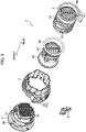
FIG. 1 is a perspective view of a rotary connector according to a first embodiment. -
FIG. 2 is an exploded perspective view of the rotary connector according to the first embodiment. -
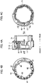
FIG. 3 is a side view of a male housing of the rotary connector according to the first embodiment. -
FIG. 4A is a side view of a bayonet ring of the rotary connector according to the first embodiment. -
FIG. 4B is a view viewed from the direction of an arrow IVB inFIG. 4A . -
FIG. 4C is a view viewed from the direction of an arrow IVC inFIG. 4A . -
FIG. 5 is a perspective view of the bayonet ring of the rotary connector according to the first embodiment. -
FIG. 6 is a perspective view of a female housing of the rotary connector according to the first embodiment. -
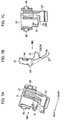
FIG. 7A is a perspective view illustrating a connector position assurance of the rotary connector according to the first embodiment. -
FIG. 7B is a view viewed from the direction of an arrow VIIB inFIG. 7A . -
FIG. 7C is a view viewed from the direction of an arrow VIIC inFIG. 7B . -
FIG. 8 is a cross-sectional perspective view of the rotary connector according to the first embodiment, illustrating a state in which the connector position assurance is located at a first position in a ready state. -
FIG. 9 is a view viewed from the direction of an arrow IX inFIG. 8 . -
FIG. 10A is a cross-sectional view illustrating a state in which the connector position assurance of the rotary connector according to the first embodiment is located at the first position. -
FIG. 10B is a cross-sectional view illustrating a state (completely bonded state) in which the rotary connector according to the embodiment is in a bonded state and the connector position assurance is located at a second position. -
FIG. 11 is a cross-sectional view corresponding toFIG. 9 (a cross-sectional view illustrating another portion), illustrating a state in which the connector position assurance is located at the first position in the ready state. -
FIG. 12A is a perspective view illustrating a connector position assurance of a rotary connector according to a second embodiment. -
FIG. 12B is a view viewed from the direction of an arrow XIIB inFIG. 12A . -
FIG. 12C is a view viewed from the direction of an arrow XIIC inFIG. 12B . -
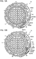
FIG. 13A is a cross-sectional view illustrating a state in which the connector position assurance of the rotary connector according to the second embodiment is located at a first position. -
FIG. 13B is a cross-sectional view illustrating a state (completely bonded state) in which the connector position assurance of the rotary connector according to the second embodiment is located at a second position. - Various embodiments will be described hereinafter with reference to the accompanying drawings.
- A rotary connector (rotation fitting connector) 1 according to a first embodiment is one in which connectors are bonded together by using a
bayonet ring 7 and the bonded state between the connectors is assured by using aconnector position assurance 9, and therotary connector 1 includes a first housing (e.g., a female housing) 3 as a first connector, a second housing (e.g., a male housing) 5 as a second connector, the bayonet ring (meshing ring) 7, and the connector position assurance (CPA) 9, as illustrated inFIGS. 1 and2 . - Herein, for convenience of description, a predetermined direction is defined as the front-rear direction. Additionally, each of the
first housing 3, thesecond housing 5, thebayonet ring 7, and the connector position assurance (housing position assurance) 9 is made of, for example, an insulating synthetic resin, and is integrally molded. - The
first housing 3 includes a first housingmain body 11, as illustrated inFIG. 6 and the like. Thesecond housing 5 is configured to be fixed to thefirst housing 3, and includes a second housingmain body 13, as illustrated inFIG. 3 and the like. - The
bayonet ring 7 includes a bayonet ringmain body 19 and a lockedportion 17 to be locked to a locking portion 15 (seeFIG. 6 ) formed in the first housing 3 (first housing main body 11), as illustrated inFIGS. 4A to 4C ,5 , and the like. The lockingportion 15 may be formed in thesecond housing 5, or may be formed in at least one of thefirst housing 3 and thesecond housing 5. - The
bayonet ring 7 is configured to engage with thefirst housing 3 and thesecond housing 5. While engaging with thefirst housing 3 and thesecond housing 5, thebayonet ring 7 is movable in a predetermined manner with respect to thefirst housing 3 and thesecond housing 5. - With the
bayonet ring 7 rotating by a predetermined angle in the direction indicated by an arrow A1 inFIG. 1 with respect to the first housing 3 (second housing 5) in a ready state in which thebayonet ring 7 engages with thefirst housing 3 and the second housing 5 (seeFIGS. 1 ,8 ,9 , and11 ), a bonded state in which thesecond housing 5 is bonded to the first housing 3 (seeFIG. 10A ) is formed. - In the bonded state, the locked
portion 17 is locked to the lockingportion 15, as illustrated inFIGS. 10A, 10B , and the like, so that the movement of thebayonet ring 7 with respect to thefirst housing 3 and thesecond housing 5 is prevented, whereby thebayonet ring 7, thefirst housing 3, and thesecond housing 5 are integrated and the bonded state between thefirst housing 3 and thesecond housing 5 is maintained. - In further description, the
bayonet ring 7 can rotate in a predetermined direction with respect to thefirst housing 3, in the above mentioned ready state. When thebayonet ring 7 rotates by a predetermined angle in a predetermined direction from the ready state, thesecond housing 5 linearly moves in the direction of approaching the first housing 3 (forward direction). - In the ready state, female terminals (not illustrated) fixed in the
first housing 3 and male terminals (not illustrated) fixed in thesecond housing 5 are away from each other. - In the bonded state, the
second housing 5 is closest to thefirst housing 3 and the lockedportion 17 is locked to the lockingportion 15, whereby thebayonet ring 7 is almost fixed with respect to thefirst housing 3 and thesecond housing 5. That is, in the bonded state, thebayonet ring 7 cannot move with respect to thefirst housing 3 and thesecond housing 5 except for backlash. So, the bonded state is maintained, which cannot be easily released. - In the bonded state, the female terminals (not illustrated) fixed in the
first housing 3 and the male terminals (not illustrated) fixed in thesecond housing 5 are connected to each other. - The
connector position assurance 9 includes an assurancemain body 21 and a contactedportion 23. The contactedportion 23 contacts acontact portion 25 provided in the bayonet ring 7 (bayonet ring main body 19). - The
connector position assurance 9 engages with thebayonet ring 7 so as to be freely movable with respect to thebayonet ring 7 between a first position P1 (seeFIGS. 8 and9 ) and a second position P2 (seeFIG. 10B ). - In the ready state, the
connector position assurance 9 is located at the first position P1, and is prevented from moving from the first position P1 (being located at the first position P1 is maintained) with the contactedportion 23 contacting thecontact portion 25, as illustrated inFIG. 11 . - On the other hand, in the bonded state, the contacted
portion 23 is away from the contact portion 25 (the contactedportion 23 is in the state of not contacting the contact portion 25), and theconnector position assurance 9 is in the state of being movable from the first position P1 to the second position P2 in the direction indicated by an arrow A2 inFIG. 10A . - When the
connector position assurance 9 is located at the second position P2, as illustrated inFIG. 10B , the state in which the lockedportion 17 is locked to the lockingportion 15 is maintained (assured). That is, the state in which the lockedportion 17 is locked to the lockingportion 15 is prevented from being released, so thebayonet ring 7 does not rotate with respect to thefirst housing 3 and thesecond housing 5. - When the
bayonet ring 7 is rotated by a predetermined angle with respect to thefirst housing 3 in the ready state, theconnector position assurance 9 located at the first position P1 also rotates integrally with thebayonet ring 7. - Alternatively, a mark, indicating that the
connector position assurance 9 is located at the first position P1 or the second position P2, may be provided in thebayonet ring 7. Thereby, the position of theconnector position assurance 9 can be easily confirmed visually. For example, it can be easily recognized visually that theconnector position assurance 9 is located at the second position P2, so the assurance of the bonded state (completely bonded state) between the first connector (the first housing 3) and the second connector (the second housing 5) can be visually confirmed. - As illustrated in
FIGS. 7A to 7C and the like, theconnector position assurance 9 includes a firstassurance contact portion 27, and a secondassurance contact portion 29 and an assurance projectedportion 31 that constitute the contactedportion 23, in addition to the assurancemain body 21. - The first
assurance contact portion 27 projects in a cantilever shape from the assurancemain body 21. The secondassurance contact portion 29 projects in a cantilever shape from the assurancemain body 21 so as to be aligned with the firstassurance contact portion 27. The assurance projectedportion 31 projects from and at the tip of the secondassurance contact portion 29. - The first housing 3 (outline of the first housing main body 11) is formed in a cylindrical shape. In the side surface of the first housing 3 (side surface of the cylinder), there is provided an arc-shaped groove (groove having a predetermined width) 33 that is recessed from the side surface and extends by a predetermined length in the circumferential direction of the side surface of the cylinder (see
FIGS. 6 ,9 , and the like). - The arc-shaped
groove 33 is interrupted (by a slight length) at one end in the longitudinal direction (arc extending direction), and the interrupted portion constitutes anon-grooved portion 35. - The bayonet ring 7 (bayonet ring main body 19) is formed in an annular shape. The
bayonet ring 7 engages with thefirst housing 3 and thesecond housing 5 such that the rear end portion in the front-rear direction of thefirst housing 3 and the front end portion in the front-rear direction of thesecond housing 5 enter inside. - As illustrated in
FIGS. 4A to 4C ,5 , and the like, thebayonet ring 7 includes a connector positionassurance support portion 37, and a bayonetring contact portion 39 constituting thecontact portion 25. - The assurance
main body 21 of theconnector position assurance 9 engages with the connector positionassurance support portion 37. The assurance main body 21 (connector position assurance 9), engaging with the connector positionassurance support portion 37 and supported by thebayonet ring 7, can move by a predetermined distance in the circumferential direction of thebayonet ring 7. - In the ready state, the assurance projected
portion 31 of theconnector position assurance 9 enters the arc-shapedgroove 33 of thefirst housing 3, and the second assurance contact portion 29 (contacted portion 23) of theconnector position assurance 9 contacts the bayonet ring contact portion 39 (contact portion 25) of thebayonet ring 7, whereby theconnector position assurance 9 is prevented from moving from the first position P1 toward the second position P2 (the movement indicated by an arrow A6 inFIG. 11 cannot be performed). - On the other hand, in the bonded state, the assurance projected
portion 31 of theconnector position assurance 9 contacts thenon-grooved portion 35 of thefirst housing 3, so a state in the middle of making a transition fromFIG. 10A to FIG. 10B is produced and the secondassurance contact portion 29 is in the state of not contacting the bayonet ring contact portion 39 (the secondassurance contact portion 29 moves outside thefirst housing 3, thesecond housing 5, and thebayonet ring 7, therefore being away from the bayonet ring contact portion 39), whereby theconnector position assurance 9 can move from the first position P1 to the second position P2. - With the
connector position assurance 9 located at the second position P2, the firstassurance contact portion 27 is located at the lockedportion 17, as illustrated inFIG. 10B , whereby the state in which the lockedportion 17 is locked to the lockingportion 15 is maintained (the completely bonded state, or the state in which the locked portion is locked to the locking portion cannot be released, is assured). - The locked
portion 17 of thebayonet ring 7 includes anelastic deformation portion 41 that elastically deforms when the lockedportion 17 is locked to the lockingportion 15 of thefirst housing 3 or when the locking of the lockedportion 17 by the lockingportion 15 is released, as illustrated inFIGS. 4A to 4C and the like. - When the locked
portion 17 is locked to the lockingportion 15 of thefirst housing 3 or when the locking of the lockedportion 17 by the lockingportion 15 is released, theelastic deformation portion 41 deforms by a first deformation amount. - When the bonded state is produced and the
connector position assurance 9 is located at the second position P2 (in the completely bonded state illustrated inFIG. 10B ), the deformation amount of theelastic deformation portion 41 is limited by the firstassurance contact portion 27, whereby the state in which the lockedportion 17 is locked to the lockingportion 15 is maintained. - That is, in the completely bonded state, the
elastic deformation portion 41 can deform only by a second deformation amount that is smaller than the first deformation amount by the firstassurance contact portion 27, whereby the state in which the lockedportion 17 is locked to the lockingportion 15 cannot be released. - When the locked
portion 17 is locked to the lockingportion 15 or when the locking of the lockedportion 17 by the lockingportion 15 is released, theelastic deformation portion 41 is restored and becomes in an undeformed state. - The locking
portion 15 of thefirst housing 3 is made of a locking projection 43 (seeFIG. 6 and the like) provided in the first housing 3 (first housing main body 11). - As illustrated in
FIGS. 4A to 4C and the like, the lockedportion 17 of thebayonet ring 7 includes theelastic deformation portion 41, an arc-shaped locked portionmain body 45, and a lockedprojection 47 provided in the locked portionmain body 45. With the lockedprojection 47 contacting the lockingprojection 43, the lockedportion 17 is locked to the lockingportion 15. - The
elastic deformation portion 41 of thebayonet ring 7 projects from the cylindrical bayonet ringmain body 19 of thebayonet ring 7, and the locked portionmain body 45 of thebayonet ring 7 is formed in an arc shape extending along the arc of the bayonet ringmain body 19, and the middle portion of this arc is bonded to the tip portion of theelastic deformation portion 41. - When the
connector position assurance 9 is located at the second position P2, the firstassurance contact portion 27 of theconnector position assurance 9 enters between thefirst housing 3 and the locked portionmain body 45 of thebayonet ring 7, as illustrated inFIG. 10B , whereby theelastic deformation portion 41 is prevented from deforming by a larger amount than the second deformation amount. That is, theelastic deformation portion 41 can deform only by a gap dimension L3 illustrated inFIG. 10B . - Herein, the
rotary connector 1 will be described in more detail. - As illustrated in
FIG. 6 , thefirst housing 3 includes aflange portion 49 and aterminal housing portion 51 that is fixed after the plurality of female terminals and cables extending from the female terminals are housed, in addition to the first housingmain body 11, the lockingportion 15, the arc-shapedgroove 33, and thenon-grooved portion 35 that have been described above. - The first housing
main body 11 is formed in a thick cylindrical shape, and the central axis of the cylinder extends in the front-rear direction. Theflange portion 49 is formed in a disc shape, and is provided at the rear end of the first housingmain body 11 by being arranged coaxially with the first housingmain body 11. Theterminal housing portion 51 is provided inside the first housingmain body 11. As for the cables with terminals (not illustrated) fixed in theterminal housing portion 51, the terminals are located on the rear side of theterminal housing portion 51, and the cables extend toward the front of theterminal housing portion 51. - The arc-shaped
groove 33 and thenon-grooved portion 35 are formed in the outer circumference of the first housingmain body 11 at the rear side of the first housingmain body 11, and the center of the arc of thegroove 33 is located on the central axis of the first housingmain body 11. - The locking portion 15 (locking projection 43) is provided on the outer circumference of the first housing
main body 11 on the front side of the first housing main body 11 (between theflange portion 49 and the arc-shapedgroove 33 in the front-rear direction). - An annular
first recess 53 is provided in the first housing 3 (first housing main body 11). Thefirst recess 53 is provided between the locking portion 15 (locking projection 43) and the arc-shapedgroove 33 in the front-rear direction. - As illustrated in
FIGS. 2 and3 , thesecond housing 5 includes aterminal housing portion 55 and a spiral groove-shapedportion 57, in addition to the second housingmain body 13. - The second housing
main body 13 is formed in a thick cylindrical shape, and the central axis of the cylinder extends in the front-rear direction. Theterminal housing portion 55 is provided inside the second housingmain body 13. As for the cables with terminals (not illustrated) fixed in theterminal housing portion 55, the terminals are located on the front side of theterminal housing portion 55, and the cables extend toward the rear of theterminal housing portion 55. - When viewed in the direction (front-rear direction) in which the central axis of the second housing
main body 13 extends, each groove-shapedportion 57 is located at the arc of a sector whose central angle centered on the central axis is a predetermined angle, for example, approximately 120 degrees. - Multiple (e.g., three) groove-shaped
portions 57 are provided, and when viewed in the front-rear direction, the respective groove-shapedportions 57 are arranged at positions where the circle of the second housingmain body 13 is equally divided (e.g., equally divided into three pieces). - Each groove-shaped
portion 57 is made of a first groove-shapedpart 59, a second groove-shapedpart 61, and a third groove-shapedpart 63. The depth dimensions and width dimensions of the respective groove-shapedparts - When each groove-shaped
portion 57 is viewed in a predetermined direction perpendicular to the front-rear direction, the first groove-shapedpart 59 extends by a slightly short length from the front end of the second housingmain body 13 toward the rear, as illustrated inFIG. 3 . The second groove-shapedpart 61 extends by a predetermined length from the rear end of the first groove-shapedpart 59 obliquely with respect to the front-rear direction. The third groove-shapedpart 63 extends by a predetermined length (a predetermined length longer than the first groove-shapedpart 59 and shorter than the second groove-shaped part 61) from the rear end of the second groove-shapedpart 61 in the direction perpendicular to the front-rear direction. - As illustrated in
FIGS. 4A to 4C and5 , thebayonet ring 7 includesengagement projections 65 and engagementconvex portions 67, in addition to the bayonet ringmain body 19, the lockedportion 17, the contact portion 25 (bayonet ring contact portion 39), and the connector positionassurance support portion 37. - The bayonet ring
main body 19 includes afront side part 73 and arear side part 75. Thefront side part 73 is formed in a cylindrical shape with arib 69 projecting inside. The inner diameter of the bayonet ring main body 19 (front side part 73, rear side part 75) is substantially equal to or slightly larger than the outer diameter of the first housingmain body 11 and the outer diameter of the second housingmain body 13. Herein, the inner diameter of thefront side part 73 of the bayonet ringmain body 19 means the diameter of an envelope circle formed at the tip of therib 69, when viewed in the front-rear direction. - As illustrated in
FIG. 5 , the connector positionassurance support portion 37 is made of asecond recess 71 that is recessed inward from the outer circumferential portion of the bayonet ringmain body 19. Thesecond recess 71 is formed in part of thefront side part 73 of the bayonet ringmain body 19 in the circumferential direction of the cylindrical bayonet ringmain body 19, and is formed in the center of thefront side part 73 in the front-rear direction. - As illustrated in
FIGS. 8 and9 , the contact portion 25 (bayonet ring contact portion 39) is made of a part of therib 69. - The locked
portion 17 is provided near thesecond recess 71 in the circumferential direction of thefront side part 73 of the cylindrical bayonet ringmain body 19, and includes theelastic deformation portion 41, the locked portionmain body 45, and the lockedprojection 47, as illustrated inFIG. 4C . - When viewed in the front-rear direction, the locked portion
main body 45 is formed in a short arc shape, and theelastic deformation portion 41 is located in the middle of the arc. The lockedprojection 47 is provided at one end of the arc of the locked portionmain body 45. - When the other end (operation unit) 81 of the arc of the locked portion
main body 45 is pushed inward as indicated by an arrow A3 inFIG. 4C , theelastic deformation portion 41 mainly deforms elastically, and the lockedprojection 47 moves outward as indicated by an arrow A4 inFIG. 4C , whereby the lockedportion 17 of thebayonet ring 7, locked to the lockingportion 15 of thefirst housing 3, moves away from the lockingportion 15. - So, the
bayonet ring 7 can rotate in the direction indicated by an arrow A5 inFIG. 10A with respect to thefirst housing 3 and thesecond housing 5, and the bonded state between thefirst housing 3 and thesecond housing 5 can be released. - Each
engagement projection 65 is formed, on the rear side of the bayonet ringmain body 19, in a short cylindrical shape that slightly projects from the inner wall of the bayonet ringmain body 19 toward the center. The outer diameter of eachcylindrical engagement projection 65 is equal to or slightly smaller than the width dimension of each groove-shapedportion 57. The height dimension of thecylindrical engagement projection 65 is smaller than the depth dimension of each groove-shapedportion 57. - The
engagement projections 65, the number of which is the same as the number of the spiral groove-shapedportions 57 of thesecond housing 5, are provided. In the ready state and bonded state, eachengagement projection 65 enters the corresponding groove-shapedportion 57. - Each engagement
convex portion 67 includes anelastic arm portion 77 and aprojection 79. Theelastic arm portion 77 extends, near the inner wall of the bayonet ringmain body 19, in the front-rear direction along the bayonet ringmain body 19, and the base end portion (rear end portion) of theelastic arm portion 77 is bonded to the bayonet ringmain body 19. - The
projection 79 slightly projects from the tip of theelastic arm portion 77 toward the center of the bayonet ringmain body 19. Multiple (e.g., three) engagementconvex portions 67 are provided, and when viewed in the front-rear direction, the engagementconvex portions 67 are arranged at positions where the circle of the bayonet ringmain body 19 is equally divided (e.g., equally divided into three pieces). - In the ready state and the bonded state, each
projection 79 of thebayonet ring 7 enters the annularfirst recess 53 of thefirst housing 3, and eachengagement projection 65 of thebayonet ring 7 enters the corresponding groove-shapedportion 57 of thesecond housing 5. - When the
bayonet ring 7 is rotated to one side with respect to thefirst housing 3 in the ready state, the bonded state is produced, and when thebayonet ring 7 is rotated to the other side with respect to thefirst housing 3 in the bonded state, the ready state is produced. - Herein, each
engagement projection 65 enters the corresponding second groove-shaped part 61 (front end portion of the second groove-shapedpart 61 of the corresponding groove-shapedportion 57 of the second housing 5) in the ready state, and eachengagement projection 65 enters the corresponding third groove-shapedpart 63 in the bonded state. - As illustrated in
FIGS. 2 and7A to 7C , theconnector position assurance 9 includes anoperation unit 83 and a pair ofprojections 85, in addition to the assurancemain body 21, the firstassurance contact portion 27, the contacted portion 23 (second assurance contact portion 29), and the assurance projectedportion 31. - When the
connector position assurance 9 is located at the first position P1 to produce the ready state, the assurance projectedportion 31, provided in the secondassurance contact portion 29 of theconnector position assurance 9, enters the arc-shapedgroove 33 provided in thefirst housing 3, and the contactedportion 23 of theconnector position assurance 9 contacts thecontact portion 25 of thebayonet ring 7, as illustrated inFIGS. 8 ,9 , and11 . This contacting prevents theconnector position assurance 9 from moving from the first position P1 to the second position P2. - When the
connector position assurance 9 is located at the first position P1 in the bonded state, the lockedportion 17 of thebayonet ring 7 is locked to the lockingportion 15 of thefirst housing 3, and the assurance projectedportion 31 of theconnector position assurance 9 contacts or is located near thenon-grooved portion 35, as illustrated inFIG. 10A . - When the
connector position assurance 9 is moving from the first position P1 to the second position in the bonded state, the lockedportion 17 of thebayonet ring 7 is locked to the lockingportion 15 of thefirst housing 3 and the assurance projectedportion 31 of theconnector position assurance 9 rides on thenon-grooved portion 35, whereby a situation is produced in which the contactedportion 23 of theconnector position assurance 9 does not contact thecontact portion 25 of thebayonet ring 7. - In a state (completely bonded state) in which the
connector position assurance 9 finishes moving from the first position P1 to the second position P2 in the bonded state, the lockedportion 17 of thebayonet ring 7 is locked to the lockingportion 15 of thefirst housing 3 and the assurance projectedportion 31 of theconnector position assurance 9 rides over thenon-grooved portion 35 to be located in the arc-shaped groove 33 (33A), as illustrated inFIG. 10B . This prevents theconnector position assurance 9 located at the second position P2 from easily moving toward the first position P1. - Further, in the completely bonded state, the first
assurance contact portion 27 enters between thefirst housing 3 and one end portion of the locked portionmain body 45 constituting the lockedportion 17 of theconnector position assurance 9, and the elastic deformation amount of theelastic deformation portion 41 of the lockedportion 17 is reduced, whereby the lockedportion 17 is prevented from being detached from the lockingportion 15. - Additionally, the
rotary connector 1 includes afront holder 87 and a packing 89, as illustrated inFIG. 2 , and in the bonded state, thefront holder 87 and the packing 89 are also integrated with thefirst housing 3, thesecond housing 5, and thebayonet ring 7. - Next, the bonding operations of the
rotary connector 1 from the ready state to the completely bonded state through the bonded state will be described. - First, in the ready state, the
bayonet ring 7 is rotated in the direction indicated by the arrow A1 inFIG. 1 with respect to thefirst housing 3, whereby the bonded state is produced. At this time (in a ready and bonded stage), thebayonet ring 7 only rotates around the central axis of thefirst housing 3 with respect to thefirst housing 3, without moving in the front-rear direction. On the other hand, thesecond housing 5 approaches thesecond housing 5 by moving forward, without rotating around the central axis of thefirst housing 3 or thesecond housing 5. - Additionally, in the ready and bonded stage, the assurance projected
portion 31 of theconnector position assurance 9 moves in the arc-shapedgroove 33 of thefirst housing 3, while the contactedportion 23 of theconnector position assurance 9 is contacting thecontact portion 25 of thebayonet ring 7. - At around the end of the ready and bonded stage, the locked
projection 47 constituting the lockedportion 17 of thebayonet ring 7 contacts the lockingprojection 43 constituting the lockingportion 15 of thefirst housing 3, and theelastic deformation portion 41 of the lockedportion 17 elastically deforms, whereby the lockedprojection 47 rides over the lockingprojection 43 to produce the bonded state. - In the bonded state, the locked
portion 17 of thebayonet ring 7 is locked to the lockingportion 15 of thefirst housing 3, and the assurance projectedportion 31 contacts thenon-grooved portion 35, as illustrated inFIG. 10A . - In the bonded state, the
connector position assurance 9 located at the first position P1 is moved to the second position P2 with respect to thebayonet ring 7. At this time, the assurance projectedportion 31 rides over thenon-grooved portion 35, so the contacted portion 23 (second assurance contact portion 29) of theconnector position assurance 9 is detached from the contact portion 25 (bayonet ring contact portion 39) of thebayonet ring 7, whereby theconnector position assurance 9 can move to the second position P2. - With the
connector position assurance 9 moving to the second position P2, the completely bonded state is produced. In the completely bonded state, the assurance projectedportion 31 enters the arc-shapedgroove 33A, and the firstassurance contact portion 27 of theconnector position assurance 9 enters the inside of the locked portionmain body 45 constituting the lockedportion 17 of thebayonet ring 7, as illustrated inFIG. 10B , whereby the elastic deformation of theelastic deformation portion 41 is suppressed. - The separation operations of the
rotary connector 1 from the completely bonded state to the ready state through the bonded state are performed through procedures reverse to the bonding operations. When a transition from the bonded state to the ready state is to be made, one end portion of the locked portion main body 45 (operation unit 81 opposite to the locked projection 47) is pushed in the direction indicated by an arrow A7 (arrow A3 inFIG. 4C ), and the other end of the locked portionmain body 45 is lifted in the direction indicated by an arrow A8 (arrow A4 inFIG. 4C ), as illustrated inFIG. 10A . - In the
rotary connector 1, the contactedportion 23 of theconnector position assurance 9 contacts thecontact portion 25 of thebayonet ring 7 in the ready state, whereby theconnector position assurance 9 is prevented from moving from the first position P1. In the bonded state, theconnector position assurance 9 can move from the first position P1 to the second position P2, and when theconnector position assurance 9 finishes moving to the second position P2, a state in which the lockedportions 17 of thebayonet ring 7 is locked to the lockingportions 15 of thefirst housing 3 is maintained (assured). Thereby, the condition in which theconnector position assurance 9 operates can be limited to when thebayonet ring 7 is rotated so that a state (bonded state) in which the bonding is performed is produced, whereby the bonded state between thesecond housing 5 and thefirst housing 3 by theconnector position assurance 9 can be assured. - In the
rotary connector 1, the assurance projectedportion 31 enters the arc-shapedgroove 33 of thefirst housing 3 and the secondassurance contact portion 29 contacts the bayonetring contact portion 39 in the ready state, whereby theconnector position assurance 9 is prevented from moving from the first position P1 to the second position P2. In the bonded state, the assurance projectedportion 31 contacts thenon-grooved portion 35, so a situation in which the secondassurance contact portion 29 does not contact the bayonetring contact portion 39 is produced, whereby theconnector position assurance 9 can move from the first position P1 to the second position P2. Additionally, thenon-grooved portion 35 is formed by being interrupted by only a slight length at one end in the direction in which the arc of the arc-shapedgroove 33 of thefirst housing 3 extends. - Thereby, the configuration of the
first housing 3 that engages with the assurance projectedportion 31 of theconnector position assurance 9 can be simplified. - According to the
rotary connector 1, when theconnector position assurance 9 is located at the second position P2 in the bonded state (when the completely bonded state is produced), the deformation amount of theelastic deformation portion 41 constituting the lockedportion 17 of thebayonet ring 7 is limited by the firstassurance contact portion 27, and the state in which the lockedportion 17 of thebayonet ring 7 is locked to the lockingportion 15 of thefirst housing 3 is maintained, whereby the state in which the lockedportion 17 of thebayonet ring 7 is locked to the lockingportion 15 of thefirst housing 3 is accurately maintained. - In the
rotary connector 1, theelastic deformation portion 41 of the lockedportion 17 of thebayonet ring 7 projects from the cylindrical bayonet ringmain body 19; the locked portionmain body 45 of the lockedportion 17 of thebayonet ring 7 is formed in an arc shape along the arc of the bayonet ringmain body 19; and the middle portion of the arc is bonded to the tip of theelastic deformation portion 41. When theconnector position assurance 9 is located at the second position P2, the firstassurance contact portion 27 enters between thefirst housing 3 and the locked portionmain body 45, whereby theelastic deformation portion 41 is prevented from deforming. - Thereby, when the completely bonded state is produced, the posture of the locked portion main body 45 (locked portion
main body 45 sandwiching the firstassurance contact portion 27 of theconnector position assurance 9 in cooperation with the first housing 3) that is provided with the lockedportion 17 and supported by theelastic deformation portion 41 can be surely maintained, whereby the state in which the lockedportion 17 of thebayonet ring 7 is locked to the lockingportion 15 of thefirst housing 3 can be surely maintained. - A
rotary connector 1a according to a second embodiment will be described with reference toFIGS. 12A to 12C ,13A, and 13B . - The
rotary connector 1a according to the second embodiment is different from therotary connector 1 according to the first embodiment in the form of a firstassurance contact portion 27a of aconnector position assurance 9a, but the other portions are configured in substantially the same manner as those of therotary connector 1 according to the first embodiment, and has substantially the same effects. - That is, in the
rotary connector 1a according to the second embodiment, the firstassurance contact portion 27a contacts the lockedportion 17 even when theconnector position assurance 9a is located at the first position P1 (seeFIG. 13A ), whereby theelastic deformation portion 41 is prevented from excessively deforming. - By preventing excessive deformation, the
elastic deformation portion 41 does not deform by more than a third deformation amount (smaller than the first deformation amount and equal to or slightly different from the second deformation amount). - In further description, in the
rotary connector 1 according to the first embodiment, there is a gap between the locked portionmain body 45 and the first housingmain body 11, the dimension of the gap being LI, as seen in the ready state and the bonded state illustrated inFIG. 10A . - On the other hand, in the
rotary connector 1a according to the second embodiment, the firstassurance contact portion 27a enters between the locked portionmain body 45 and the first housingmain body 11, and hence there is a gap between the locked portionmain body 45 and the firstassurance contact portion 27a, the dimension of the gap being only L2 (L2 < L1), as seen in the ready state and the bonded state illustrated inFIG. 13A . This prevents theelastic deformation portion 41 from excessively deforming. - In the completely bonded state, the deformation amount of the
elastic deformation portion 41 of the lockingportion 15 is reduced similarly to therotary connector 1 according to the first embodiment, as illustrated inFIG. 13B , whereby the state in which the lockedportion 17 of thebayonet ring 7 is locked to the lockingportion 15 of thefirst housing 3 is maintained. - According to the
rotary connector 1a of the second embodiment, the firstassurance contact portion 27a of theconnector position assurance 9a contacts the lockedportion 17 of thebayonet ring 7 even when theconnector position assurance 9a is located at the first position P1, whereby the elastic deformation portion of the lockedportion 17 of thebayonet ring 7 is prevented from excessively deforming; and hence theelastic deformation portion 41 of the lockedportion 17 of thebayonet ring 7 is prevented from excessively deforming, regardless of the position of theconnector position assurance 9a with respect to thebayonet ring 7, whereby the durability of the lockedportion 17 of thebayonet ring 7 can be secured, and damages etc., of the lockedportion 17 of thebayonet ring 7 can be prevented. - Each of the
above rotary connectors first housing 3, asecond housing 5, abayonet ring 7, and aconnector position assurance bayonet ring 7 engaging with thefirst housing 3 and thesecond housing 5, thefirst housing 3 and thesecond housing 5 are bonded together; in a ready state before thefirst housing 3 and thesecond housing 5 are bonded together, theconnector position assurance bayonet ring 7 is prevented from moving; in a bonded state in which thesecond housing 5 is bonded to thefirst housing 3, theconnector position assurance bayonet ring 7 can move; and by moving theconnector position assurance bayonet ring 7 in the bonded state in which thesecond housing 5 is bonded to thefirst housing 3, the state in which thesecond housing 5 is bonded to thefirst housing 3 is maintained. - Although the present invention has been described above by reference to the embodiments, the present invention is not limited to those and the configuration of parts can be replaced with any configuration having a similar function, as long as they lie within the scope of the claims.
Claims (6)
- A rotary connector, comprising:a first housing;a second housing that is fixed to the first housing;a locking portion formed in at least one of the first housing and the second housing;a bayonet ring comprising a locked portion to be locked to the locking portion, the bayonet ring configured to form, in a ready state of engaging with the first housing and the second housing, a bonded state in which the second housing is bonded to the first housing by rotating by a predetermined angle with respect to the first housing, and configured to be prevented, in the bonded state, from rotating with respect to the first housing with the locked portion locked to the locking portion;a contact portion formed on the bayonet ring; anda connector position assurance comprising a contacted portion to contact the contact portion, and capable of engaging with the bayonet ring,in the ready state, the connector position assurance located at a first position and prevented from moving from the first position with the contacted portion contacting the contact portion,in the bonded state, the connector position assurance capable of moving from the first position to a second position with the contacted portion moving away from the contact portion, andwhen being located at the second position, the connector position assurance maintaining the state in which the locked portion is locked to the locking portion.
- The rotary connector of claim 1, wherein:the connector position assurance comprisesan assurance main body,a first assurance contact part projecting from the assurance main body,a second assurance contact part projecting from the assurance main body and constituting the contacted portion, andan assurance projected portion projecting from and at a tip of the second assurance contact part;the first housing is formed in a cylindrical shape;in a side surface of the first housing, an arc-shaped groove extending by a predetermined length in a circumferential direction of the side surface is provided;the arc-shaped groove is interrupted at one end in its longitudinal direction, the interrupted portion constituting a non-grooved portion;the bayonet ring is formed in an annular shape, and engages with the first housing such that the first housing enters inside;the bayonet ring comprisesa connector position assurance support portion that supports the connector position assurance such that the connector position assurance moves in a circumferential direction of the bayonet ring with the assurance main body engaging, anda bayonet ring contact portion that constitutes the contact portion and that the second assurance contact part contacts;in the ready state, the assurance projected portion enters the arc-shaped groove and the second assurance contact part contacts the bayonet ring contact portion, whereby the connector position assurance is prevented from moving from the first position; andin the bonded state, the assurance projected portion contacts the non-grooved portion, so that the second assurance contact part is in a state of not contacting the bayonet ring contact portion and the connector position assurance is moveable from the first position to the second position, andsince the connector position assurance is located at the second position, the first assurance contact part engages with the locked portion, whereby the state in which the locked portion is locked to the locking portion is maintained.
- The rotary connector of claim 2, wherein:the locked portion comprised an elastic deformation portion that elastically deforms when being locked to the locking portion; andwhen the connector position assurance is located at the second position in the bonded state, a deformation amount of the elastic deformation portion is limited by the first assurance contact part, whereby the state in which the locked portion is locked to the locking portion is maintained.
- The rotary connector of claim 3, wherein
in a state in which the connector position assurance is located at the first position, the first assurance contact part contacts the locked portion, whereby the elastic deformation portion is prevented from excessively deforming. - The rotary connector of claim 3 or 4, wherein:the locking portion is made of a locking projection provided in the first housing;the locked portion comprises the elastic deformation portion, an arc-shaped locked portion main body, and a locked projection provided in the locked portion main body;the locked portion is locked to the locking portion with the locked projection contacting the locking projection;the elastic deformation portion projects from a cylindrical bayonet ring main body of the bayonet ring;the locked portion main body is formed in an arc shape extending along an arc of the bayonet ring main body;a middle portion of the arc of the bayonet ring main body is bonded to a tip of the elastic deformation portion; andwhen the connector position assurance is located at the second position, the first assurance contact part enters between the bayonet ring and the locked portion main body, whereby the elastic deformation portion is prevented from deforming.
- A rotary connector, comprising:a first housing;a second housing;a bayonet ring; anda connector position assurance, wherein:the first housing and the second housing are bonded together by rotating the bayonet ring engaging with the first housing and the second housing;in a ready state before the first housing and the second housing are bonded together, the connector position assurance engaging with the bayonet ring is prevented from moving;in a bonded state in which the first housing and the second housing are bonded together, the connector position assurance engaging with the bayonet ring is moveable; andby moving the connector position assurance engaging with the bayonet ring in the bonded state in which the first housing and the second housing are bonded together, the state in which the first housing and the second housing are bonded together is maintained.
Applications Claiming Priority (1)
| Application Number | Priority Date | Filing Date | Title |
|---|---|---|---|
| JP2019076853A JP6916238B2 (en) | 2019-04-15 | 2019-04-15 | Rotary connector |
Publications (2)
| Publication Number | Publication Date |
|---|---|
| EP3726664A1 true EP3726664A1 (en) | 2020-10-21 |
| EP3726664B1 EP3726664B1 (en) | 2022-07-20 |
Family
ID=70189853
Family Applications (1)
| Application Number | Title | Priority Date | Filing Date |
|---|---|---|---|
| EP20168195.4A Active EP3726664B1 (en) | 2019-04-15 | 2020-04-06 | Rotary connector |
Country Status (3)
| Country | Link |
|---|---|
| US (1) | US11569610B2 (en) |
| EP (1) | EP3726664B1 (en) |
| JP (1) | JP6916238B2 (en) |
Families Citing this family (6)
| Publication number | Priority date | Publication date | Assignee | Title |
|---|---|---|---|---|
| JP6916238B2 (en) * | 2019-04-15 | 2021-08-11 | 矢崎総業株式会社 | Rotary connector |
| CN115117668A (en) | 2021-03-19 | 2022-09-27 | 泰科电子(上海)有限公司 | Connectors and Connector Components |
| CN214625474U (en) | 2021-03-19 | 2021-11-05 | 泰科电子(上海)有限公司 | Connectors and Connector Components |
| CN115117669B (en) * | 2021-03-19 | 2025-07-04 | 泰科电子(上海)有限公司 | Connectors and Connector Assemblies |
| CN214625501U (en) | 2021-03-19 | 2021-11-05 | 泰科电子(上海)有限公司 | Connector and connector assembly |
| JP2023041136A (en) * | 2021-09-13 | 2023-03-24 | 矢崎総業株式会社 | connector |
Citations (4)
| Publication number | Priority date | Publication date | Assignee | Title |
|---|---|---|---|---|
| US5980293A (en) * | 1996-11-25 | 1999-11-09 | Yazaki Corporation | Mechanism for ascertaining fitting condition of electrical connector assembly |
| US6280221B1 (en) * | 1999-08-02 | 2001-08-28 | Yazaki Corporation | Electric connector housing and method for detecting engagement of the same |
| JP2005267930A (en) | 2004-03-17 | 2005-09-29 | Yazaki Corp | Rotating mating connector |
| JP2009505343A (en) | 2005-08-12 | 2009-02-05 | コスタール・コンタクト・ジステーメ・ゲゼルシャフト・ミト・ベシュレンクテル・ハフツング | Electrical plug connector |
Family Cites Families (9)
| Publication number | Priority date | Publication date | Assignee | Title |
|---|---|---|---|---|
| CA1296079C (en) * | 1986-03-06 | 1992-02-18 | Mitsuru Takeda | Locked connector |
| JP3188983B2 (en) * | 1992-04-25 | 2001-07-16 | 能美防災株式会社 | Sensor base |
| JP2914088B2 (en) * | 1993-04-16 | 1999-06-28 | 住友電装株式会社 | Connector with rotation guide |
| US6297741B1 (en) * | 1999-07-09 | 2001-10-02 | Vibro-Meter S.A. | Mechanism for retaining a removable element in a mounting structure |
| US6368133B1 (en) * | 1999-11-19 | 2002-04-09 | Milwaukee Electric Tool Corporation | Quick lock power cord |
| JP3943914B2 (en) * | 2001-11-26 | 2007-07-11 | 矢崎総業株式会社 | connector |
| JP3838934B2 (en) * | 2002-04-19 | 2006-10-25 | 株式会社ユタカ製作所 | Electrical wiring coupler |
| DE202010017274U1 (en) * | 2010-04-28 | 2011-09-23 | Amphenol-Tuchel Electronics Gmbh | Electrical connector, in particular round connector |
| JP6916238B2 (en) * | 2019-04-15 | 2021-08-11 | 矢崎総業株式会社 | Rotary connector |
-
2019
- 2019-04-15 JP JP2019076853A patent/JP6916238B2/en active Active
-
2020
- 2020-04-06 EP EP20168195.4A patent/EP3726664B1/en active Active
- 2020-04-14 US US16/847,887 patent/US11569610B2/en active Active
Patent Citations (4)
| Publication number | Priority date | Publication date | Assignee | Title |
|---|---|---|---|---|
| US5980293A (en) * | 1996-11-25 | 1999-11-09 | Yazaki Corporation | Mechanism for ascertaining fitting condition of electrical connector assembly |
| US6280221B1 (en) * | 1999-08-02 | 2001-08-28 | Yazaki Corporation | Electric connector housing and method for detecting engagement of the same |
| JP2005267930A (en) | 2004-03-17 | 2005-09-29 | Yazaki Corp | Rotating mating connector |
| JP2009505343A (en) | 2005-08-12 | 2009-02-05 | コスタール・コンタクト・ジステーメ・ゲゼルシャフト・ミト・ベシュレンクテル・ハフツング | Electrical plug connector |
Also Published As
| Publication number | Publication date |
|---|---|
| JP6916238B2 (en) | 2021-08-11 |
| US11569610B2 (en) | 2023-01-31 |
| US20200325941A1 (en) | 2020-10-15 |
| EP3726664B1 (en) | 2022-07-20 |
| JP2020177726A (en) | 2020-10-29 |
Similar Documents
| Publication | Publication Date | Title |
|---|---|---|
| EP3726664B1 (en) | Rotary connector | |
| JP3943914B2 (en) | connector | |
| JP2005267930A (en) | Rotating mating connector | |
| CN107768891B (en) | connector device | |
| US4497530A (en) | Electrical connector having a coupling indicator | |
| CN108808314B (en) | Electrical connector assembly for airbag ignition mechanism | |
| EP0237423B1 (en) | Locked connector | |
| JPH06302356A (en) | Connector with rotation guide | |
| MY105011A (en) | Connector with locking mechanism. | |
| US4078849A (en) | Electronic connector | |
| JP2020087580A (en) | connector | |
| US9929505B2 (en) | Connector | |
| US4239315A (en) | Electrical connector | |
| JP6023892B2 (en) | Female terminal | |
| JP2007179860A (en) | connector | |
| CA3172562A1 (en) | Device for connecting two tubular objects | |
| US3851946A (en) | Cable connecting assembly | |
| CN110034458A (en) | Connector | |
| US8079868B2 (en) | Electrical connector with releasable locking clip | |
| JPH09240488A (en) | Circuit connection device for vehicle steering module | |
| JP2020149783A (en) | connector | |
| CN116941143A (en) | Rod type connector | |
| EP3896796A1 (en) | Connector unit and connector | |
| CN117501552A (en) | Connector | |
| JP4588663B2 (en) | connector |
Legal Events
| Date | Code | Title | Description |
|---|---|---|---|
| PUAI | Public reference made under article 153(3) epc to a published international application that has entered the european phase |
Free format text: ORIGINAL CODE: 0009012 |
|
| STAA | Information on the status of an ep patent application or granted ep patent |
Free format text: STATUS: REQUEST FOR EXAMINATION WAS MADE |
|
| 17P | Request for examination filed |
Effective date: 20200406 |
|
| AK | Designated contracting states |
Kind code of ref document: A1 Designated state(s): AL AT BE BG CH CY CZ DE DK EE ES FI FR GB GR HR HU IE IS IT LI LT LU LV MC MK MT NL NO PL PT RO RS SE SI SK SM TR |
|
| AX | Request for extension of the european patent |
Extension state: BA ME |
|
| RBV | Designated contracting states (corrected) |
Designated state(s): AL AT BE BG CH CY CZ DE DK EE ES FI FR GB GR HR HU IE IS IT LI LT LU LV MC MK MT NL NO PL PT RO RS SE SI SK SM TR |
|
| STAA | Information on the status of an ep patent application or granted ep patent |
Free format text: STATUS: EXAMINATION IS IN PROGRESS |
|
| 17Q | First examination report despatched |
Effective date: 20210730 |
|
| GRAP | Despatch of communication of intention to grant a patent |
Free format text: ORIGINAL CODE: EPIDOSNIGR1 |
|
| STAA | Information on the status of an ep patent application or granted ep patent |
Free format text: STATUS: GRANT OF PATENT IS INTENDED |
|
| RIC1 | Information provided on ipc code assigned before grant |
Ipc: H01R 107/00 20060101ALN20220408BHEP Ipc: H01R 13/623 20060101ALN20220408BHEP Ipc: H01R 13/641 20060101ALI20220408BHEP Ipc: H01R 13/639 20060101ALI20220408BHEP Ipc: H01R 13/625 20060101AFI20220408BHEP |
|
| INTG | Intention to grant announced |
Effective date: 20220429 |
|
| GRAS | Grant fee paid |
Free format text: ORIGINAL CODE: EPIDOSNIGR3 |
|
| GRAA | (expected) grant |
Free format text: ORIGINAL CODE: 0009210 |
|
| STAA | Information on the status of an ep patent application or granted ep patent |
Free format text: STATUS: THE PATENT HAS BEEN GRANTED |
|
| AK | Designated contracting states |
Kind code of ref document: B1 Designated state(s): AL AT BE BG CH CY CZ DE DK EE ES FI FR GB GR HR HU IE IS IT LI LT LU LV MC MK MT NL NO PL PT RO RS SE SI SK SM TR |
|
| REG | Reference to a national code |
Ref country code: CH Ref legal event code: EP |
|
| REG | Reference to a national code |
Ref country code: DE Ref legal event code: R096 Ref document number: 602020004040 Country of ref document: DE |
|
| REG | Reference to a national code |
Ref country code: AT Ref legal event code: REF Ref document number: 1506152 Country of ref document: AT Kind code of ref document: T Effective date: 20220815 |
|
| REG | Reference to a national code |
Ref country code: IE Ref legal event code: FG4D |
|
| REG | Reference to a national code |
Ref country code: LT Ref legal event code: MG9D |
|
| REG | Reference to a national code |
Ref country code: NL Ref legal event code: MP Effective date: 20220720 |
|
| PG25 | Lapsed in a contracting state [announced via postgrant information from national office to epo] |
Ref country code: SE Free format text: LAPSE BECAUSE OF FAILURE TO SUBMIT A TRANSLATION OF THE DESCRIPTION OR TO PAY THE FEE WITHIN THE PRESCRIBED TIME-LIMIT Effective date: 20220720 Ref country code: RS Free format text: LAPSE BECAUSE OF FAILURE TO SUBMIT A TRANSLATION OF THE DESCRIPTION OR TO PAY THE FEE WITHIN THE PRESCRIBED TIME-LIMIT Effective date: 20220720 Ref country code: PT Free format text: LAPSE BECAUSE OF FAILURE TO SUBMIT A TRANSLATION OF THE DESCRIPTION OR TO PAY THE FEE WITHIN THE PRESCRIBED TIME-LIMIT Effective date: 20221121 Ref country code: NO Free format text: LAPSE BECAUSE OF FAILURE TO SUBMIT A TRANSLATION OF THE DESCRIPTION OR TO PAY THE FEE WITHIN THE PRESCRIBED TIME-LIMIT Effective date: 20221020 Ref country code: NL Free format text: LAPSE BECAUSE OF FAILURE TO SUBMIT A TRANSLATION OF THE DESCRIPTION OR TO PAY THE FEE WITHIN THE PRESCRIBED TIME-LIMIT Effective date: 20220720 Ref country code: LV Free format text: LAPSE BECAUSE OF FAILURE TO SUBMIT A TRANSLATION OF THE DESCRIPTION OR TO PAY THE FEE WITHIN THE PRESCRIBED TIME-LIMIT Effective date: 20220720 Ref country code: LT Free format text: LAPSE BECAUSE OF FAILURE TO SUBMIT A TRANSLATION OF THE DESCRIPTION OR TO PAY THE FEE WITHIN THE PRESCRIBED TIME-LIMIT Effective date: 20220720 Ref country code: FI Free format text: LAPSE BECAUSE OF FAILURE TO SUBMIT A TRANSLATION OF THE DESCRIPTION OR TO PAY THE FEE WITHIN THE PRESCRIBED TIME-LIMIT Effective date: 20220720 Ref country code: ES Free format text: LAPSE BECAUSE OF FAILURE TO SUBMIT A TRANSLATION OF THE DESCRIPTION OR TO PAY THE FEE WITHIN THE PRESCRIBED TIME-LIMIT Effective date: 20220720 |
|
| REG | Reference to a national code |
Ref country code: AT Ref legal event code: MK05 Ref document number: 1506152 Country of ref document: AT Kind code of ref document: T Effective date: 20220720 |
|
| PG25 | Lapsed in a contracting state [announced via postgrant information from national office to epo] |
Ref country code: PL Free format text: LAPSE BECAUSE OF FAILURE TO SUBMIT A TRANSLATION OF THE DESCRIPTION OR TO PAY THE FEE WITHIN THE PRESCRIBED TIME-LIMIT Effective date: 20220720 Ref country code: IS Free format text: LAPSE BECAUSE OF FAILURE TO SUBMIT A TRANSLATION OF THE DESCRIPTION OR TO PAY THE FEE WITHIN THE PRESCRIBED TIME-LIMIT Effective date: 20221120 Ref country code: HR Free format text: LAPSE BECAUSE OF FAILURE TO SUBMIT A TRANSLATION OF THE DESCRIPTION OR TO PAY THE FEE WITHIN THE PRESCRIBED TIME-LIMIT Effective date: 20220720 Ref country code: GR Free format text: LAPSE BECAUSE OF FAILURE TO SUBMIT A TRANSLATION OF THE DESCRIPTION OR TO PAY THE FEE WITHIN THE PRESCRIBED TIME-LIMIT Effective date: 20221021 |
|
| REG | Reference to a national code |
Ref country code: DE Ref legal event code: R097 Ref document number: 602020004040 Country of ref document: DE |
|
| PG25 | Lapsed in a contracting state [announced via postgrant information from national office to epo] |
Ref country code: SM Free format text: LAPSE BECAUSE OF FAILURE TO SUBMIT A TRANSLATION OF THE DESCRIPTION OR TO PAY THE FEE WITHIN THE PRESCRIBED TIME-LIMIT Effective date: 20220720 Ref country code: RO Free format text: LAPSE BECAUSE OF FAILURE TO SUBMIT A TRANSLATION OF THE DESCRIPTION OR TO PAY THE FEE WITHIN THE PRESCRIBED TIME-LIMIT Effective date: 20220720 Ref country code: DK Free format text: LAPSE BECAUSE OF FAILURE TO SUBMIT A TRANSLATION OF THE DESCRIPTION OR TO PAY THE FEE WITHIN THE PRESCRIBED TIME-LIMIT Effective date: 20220720 Ref country code: CZ Free format text: LAPSE BECAUSE OF FAILURE TO SUBMIT A TRANSLATION OF THE DESCRIPTION OR TO PAY THE FEE WITHIN THE PRESCRIBED TIME-LIMIT Effective date: 20220720 Ref country code: AT Free format text: LAPSE BECAUSE OF FAILURE TO SUBMIT A TRANSLATION OF THE DESCRIPTION OR TO PAY THE FEE WITHIN THE PRESCRIBED TIME-LIMIT Effective date: 20220720 |
|
| PLBE | No opposition filed within time limit |
Free format text: ORIGINAL CODE: 0009261 |
|
| STAA | Information on the status of an ep patent application or granted ep patent |
Free format text: STATUS: NO OPPOSITION FILED WITHIN TIME LIMIT |
|
| PG25 | Lapsed in a contracting state [announced via postgrant information from national office to epo] |
Ref country code: SK Free format text: LAPSE BECAUSE OF FAILURE TO SUBMIT A TRANSLATION OF THE DESCRIPTION OR TO PAY THE FEE WITHIN THE PRESCRIBED TIME-LIMIT Effective date: 20220720 Ref country code: EE Free format text: LAPSE BECAUSE OF FAILURE TO SUBMIT A TRANSLATION OF THE DESCRIPTION OR TO PAY THE FEE WITHIN THE PRESCRIBED TIME-LIMIT Effective date: 20220720 |
|
| 26N | No opposition filed |
Effective date: 20230421 |
|
| PG25 | Lapsed in a contracting state [announced via postgrant information from national office to epo] |
Ref country code: AL Free format text: LAPSE BECAUSE OF FAILURE TO SUBMIT A TRANSLATION OF THE DESCRIPTION OR TO PAY THE FEE WITHIN THE PRESCRIBED TIME-LIMIT Effective date: 20220720 |
|
| PG25 | Lapsed in a contracting state [announced via postgrant information from national office to epo] |
Ref country code: SI Free format text: LAPSE BECAUSE OF FAILURE TO SUBMIT A TRANSLATION OF THE DESCRIPTION OR TO PAY THE FEE WITHIN THE PRESCRIBED TIME-LIMIT Effective date: 20220720 |
|
| REG | Reference to a national code |
Ref country code: CH Ref legal event code: PL |
|
| PG25 | Lapsed in a contracting state [announced via postgrant information from national office to epo] |
Ref country code: LU Free format text: LAPSE BECAUSE OF NON-PAYMENT OF DUE FEES Effective date: 20230406 |
|
| REG | Reference to a national code |
Ref country code: BE Ref legal event code: MM Effective date: 20230430 |
|
| PG25 | Lapsed in a contracting state [announced via postgrant information from national office to epo] |
Ref country code: MC Free format text: LAPSE BECAUSE OF FAILURE TO SUBMIT A TRANSLATION OF THE DESCRIPTION OR TO PAY THE FEE WITHIN THE PRESCRIBED TIME-LIMIT Effective date: 20220720 |
|
| PG25 | Lapsed in a contracting state [announced via postgrant information from national office to epo] |
Ref country code: MC Free format text: LAPSE BECAUSE OF FAILURE TO SUBMIT A TRANSLATION OF THE DESCRIPTION OR TO PAY THE FEE WITHIN THE PRESCRIBED TIME-LIMIT Effective date: 20220720 Ref country code: LI Free format text: LAPSE BECAUSE OF NON-PAYMENT OF DUE FEES Effective date: 20230430 Ref country code: CH Free format text: LAPSE BECAUSE OF NON-PAYMENT OF DUE FEES Effective date: 20230430 |
|
| REG | Reference to a national code |
Ref country code: IE Ref legal event code: MM4A |
|
| PG25 | Lapsed in a contracting state [announced via postgrant information from national office to epo] |
Ref country code: BE Free format text: LAPSE BECAUSE OF NON-PAYMENT OF DUE FEES Effective date: 20230430 |
|
| PG25 | Lapsed in a contracting state [announced via postgrant information from national office to epo] |
Ref country code: IE Free format text: LAPSE BECAUSE OF NON-PAYMENT OF DUE FEES Effective date: 20230406 |
|
| PG25 | Lapsed in a contracting state [announced via postgrant information from national office to epo] |
Ref country code: IE Free format text: LAPSE BECAUSE OF NON-PAYMENT OF DUE FEES Effective date: 20230406 |
|
| PG25 | Lapsed in a contracting state [announced via postgrant information from national office to epo] |
Ref country code: IT Free format text: LAPSE BECAUSE OF FAILURE TO SUBMIT A TRANSLATION OF THE DESCRIPTION OR TO PAY THE FEE WITHIN THE PRESCRIBED TIME-LIMIT Effective date: 20220720 |
|
| PG25 | Lapsed in a contracting state [announced via postgrant information from national office to epo] |
Ref country code: BG Free format text: LAPSE BECAUSE OF FAILURE TO SUBMIT A TRANSLATION OF THE DESCRIPTION OR TO PAY THE FEE WITHIN THE PRESCRIBED TIME-LIMIT Effective date: 20220720 |
|
| PG25 | Lapsed in a contracting state [announced via postgrant information from national office to epo] |
Ref country code: BG Free format text: LAPSE BECAUSE OF FAILURE TO SUBMIT A TRANSLATION OF THE DESCRIPTION OR TO PAY THE FEE WITHIN THE PRESCRIBED TIME-LIMIT Effective date: 20220720 |
|
| GBPC | Gb: european patent ceased through non-payment of renewal fee |
Effective date: 20240406 |
|
| PG25 | Lapsed in a contracting state [announced via postgrant information from national office to epo] |
Ref country code: GB Free format text: LAPSE BECAUSE OF NON-PAYMENT OF DUE FEES Effective date: 20240406 |
|
| PG25 | Lapsed in a contracting state [announced via postgrant information from national office to epo] |
Ref country code: GB Free format text: LAPSE BECAUSE OF NON-PAYMENT OF DUE FEES Effective date: 20240406 |
|
| PGFP | Annual fee paid to national office [announced via postgrant information from national office to epo] |
Ref country code: DE Payment date: 20250305 Year of fee payment: 6 |
|
| PG25 | Lapsed in a contracting state [announced via postgrant information from national office to epo] |
Ref country code: CY Free format text: LAPSE BECAUSE OF FAILURE TO SUBMIT A TRANSLATION OF THE DESCRIPTION OR TO PAY THE FEE WITHIN THE PRESCRIBED TIME-LIMIT; INVALID AB INITIO Effective date: 20200406 |
|
| PG25 | Lapsed in a contracting state [announced via postgrant information from national office to epo] |
Ref country code: HU Free format text: LAPSE BECAUSE OF FAILURE TO SUBMIT A TRANSLATION OF THE DESCRIPTION OR TO PAY THE FEE WITHIN THE PRESCRIBED TIME-LIMIT; INVALID AB INITIO Effective date: 20200406 |
|
| PG25 | Lapsed in a contracting state [announced via postgrant information from national office to epo] |
Ref country code: TR Free format text: LAPSE BECAUSE OF FAILURE TO SUBMIT A TRANSLATION OF THE DESCRIPTION OR TO PAY THE FEE WITHIN THE PRESCRIBED TIME-LIMIT Effective date: 20220720 |
|
| PGFP | Annual fee paid to national office [announced via postgrant information from national office to epo] |
Ref country code: FR Payment date: 20260309 Year of fee payment: 7 |