EP3726650A1 - Multi-arm spiral antenna for a wireless device - Google Patents
Multi-arm spiral antenna for a wireless device Download PDFInfo
- Publication number
- EP3726650A1 EP3726650A1 EP20165519.8A EP20165519A EP3726650A1 EP 3726650 A1 EP3726650 A1 EP 3726650A1 EP 20165519 A EP20165519 A EP 20165519A EP 3726650 A1 EP3726650 A1 EP 3726650A1
- Authority
- EP
- European Patent Office
- Prior art keywords
- arms
- antenna
- coupled
- ring
- wearable audio
- Prior art date
- Legal status (The legal status is an assumption and is not a legal conclusion. Google has not performed a legal analysis and makes no representation as to the accuracy of the status listed.)
- Granted
Links
Images


Classifications
-
- H—ELECTRICITY
- H01—ELECTRIC ELEMENTS
- H01Q—ANTENNAS, i.e. RADIO AERIALS
- H01Q1/00—Details of, or arrangements associated with, antennas
- H01Q1/27—Adaptation for use in or on movable bodies
- H01Q1/273—Adaptation for carrying or wearing by persons or animals
-
- H—ELECTRICITY
- H01—ELECTRIC ELEMENTS
- H01Q—ANTENNAS, i.e. RADIO AERIALS
- H01Q1/00—Details of, or arrangements associated with, antennas
- H01Q1/36—Structural form of radiating elements, e.g. cone, spiral, umbrella; Particular materials used therewith
-
- H—ELECTRICITY
- H01—ELECTRIC ELEMENTS
- H01Q—ANTENNAS, i.e. RADIO AERIALS
- H01Q1/00—Details of, or arrangements associated with, antennas
- H01Q1/36—Structural form of radiating elements, e.g. cone, spiral, umbrella; Particular materials used therewith
- H01Q1/362—Structural form of radiating elements, e.g. cone, spiral, umbrella; Particular materials used therewith for broadside radiating helical antennas
-
- H—ELECTRICITY
- H01—ELECTRIC ELEMENTS
- H01Q—ANTENNAS, i.e. RADIO AERIALS
- H01Q1/00—Details of, or arrangements associated with, antennas
- H01Q1/48—Earthing means; Earth screens; Counterpoises
-
- H—ELECTRICITY
- H01—ELECTRIC ELEMENTS
- H01Q—ANTENNAS, i.e. RADIO AERIALS
- H01Q11/00—Electrically-long antennas having dimensions more than twice the shortest operating wavelength and consisting of conductive active radiating elements
- H01Q11/02—Non-resonant antennas, e.g. travelling-wave antenna
- H01Q11/08—Helical antennas
-
- H—ELECTRICITY
- H01—ELECTRIC ELEMENTS
- H01Q—ANTENNAS, i.e. RADIO AERIALS
- H01Q7/00—Loop antennas with a substantially uniform current distribution around the loop and having a directional radiation pattern in a plane perpendicular to the plane of the loop
-
- H—ELECTRICITY
- H04—ELECTRIC COMMUNICATION TECHNIQUE
- H04R—LOUDSPEAKERS, MICROPHONES, GRAMOPHONE PICK-UPS OR LIKE ACOUSTIC ELECTROMECHANICAL TRANSDUCERS; ELECTRIC HEARING AIDS; PUBLIC ADDRESS SYSTEMS
- H04R1/00—Details of transducers, loudspeakers or microphones
- H04R1/10—Earpieces; Attachments therefor ; Earphones; Monophonic headphones
- H04R1/1041—Mechanical or electronic switches, or control elements
-
- H—ELECTRICITY
- H04—ELECTRIC COMMUNICATION TECHNIQUE
- H04R—LOUDSPEAKERS, MICROPHONES, GRAMOPHONE PICK-UPS OR LIKE ACOUSTIC ELECTROMECHANICAL TRANSDUCERS; ELECTRIC HEARING AIDS; PUBLIC ADDRESS SYSTEMS
- H04R1/00—Details of transducers, loudspeakers or microphones
- H04R1/10—Earpieces; Attachments therefor ; Earphones; Monophonic headphones
- H04R1/1008—Earpieces of the supra-aural or circum-aural type
-
- H—ELECTRICITY
- H04—ELECTRIC COMMUNICATION TECHNIQUE
- H04R—LOUDSPEAKERS, MICROPHONES, GRAMOPHONE PICK-UPS OR LIKE ACOUSTIC ELECTROMECHANICAL TRANSDUCERS; ELECTRIC HEARING AIDS; PUBLIC ADDRESS SYSTEMS
- H04R1/00—Details of transducers, loudspeakers or microphones
- H04R1/10—Earpieces; Attachments therefor ; Earphones; Monophonic headphones
- H04R1/1016—Earpieces of the intra-aural type
-
- H—ELECTRICITY
- H04—ELECTRIC COMMUNICATION TECHNIQUE
- H04R—LOUDSPEAKERS, MICROPHONES, GRAMOPHONE PICK-UPS OR LIKE ACOUSTIC ELECTROMECHANICAL TRANSDUCERS; ELECTRIC HEARING AIDS; PUBLIC ADDRESS SYSTEMS
- H04R2420/00—Details of connection covered by H04R, not provided for in its groups
- H04R2420/07—Applications of wireless loudspeakers or wireless microphones
Definitions
- At least one example in accordance with the present disclosure relates generally to wireless devices, including wireless headphones.
- Wireless headphones may include one or more components to enable wireless communication with an audio source.
- wireless headphones may include antennas configured to send and receive signals encoding audio information to and from an audio source.
- a form factor of the antenna may be restricted by a need for a headphone to fit partially within a user's ear canal.
- the arms of the plurality of arms are configured to be evenly spaced around a circumference of the ring.
- the plurality of arms comprises four arms.
- the device includes a plurality of conducting ports, wherein each arm is configured to be coupled to the ground plane via a respective conducting port of the plurality of conducting ports.
- the plurality of arms comprises three arms.
- each arm is configured to be coupled directly to the ground plane.
- the elliptically polarized monopole antenna is configured to be formed on a surface of the enclosure.
- an antenna including a ring, and a plurality of arms, each arm of the plurality of arms having a first connection coupled to the ring, and a second connection configured to be coupled to a ground plane, the plurality of arms being arranged such that the antenna is an elliptically polarized spiral monopole antenna, wherein the antenna is configured to be formed on a surface of an enclosure of a wearable audio device, the enclosure being configured to be coupled to an ear of a user.
- the arms of the plurality of arms are configured to be evenly separated around a circumference of the ring and around a circumference of the ground plane.
- the plurality of arms comprises four arms.
- each arm is configured to be coupled to the ground plane via a conducting port.
- the plurality of arms comprises three arms.
- each arm is configured to be coupled directly to the ground plane.
- the antenna is configured to be formed on the surface of the wearable audio device enclosure.
- Wireless headphone antennas may be designed with a circular or an elliptical (which may be circular or non-circular) polarization along a broadside of the antenna.
- an elliptically polarized monopole antenna is coupled to a small ground plane.
- the diameter of the antenna is approximately equal to the diameter of the ground plane.
- the antenna may include one or more spiral arms. These spiral arms may include one or more Archimedean spiral arms. One end of each spiral arm may be connected to a ring centered above a ground disc. A second end of the spiral arm may be connected to the ground disc either directly or via a conducting port. The ends of the spiral arms may be evenly separated around a circumference of the ring and the ground plane.
- a circularly or elliptically polarized monopole antenna may be beneficial in a low-profile wearable device that does not extend from a user's ear canal or pinna significantly or at all.
- the antenna is configured to receive both horizontally or vertically polarized components of electromagnetic radiation propagating along a referenced observation interface, such as the surface of a human body.
- the antenna may have an advantageously low profile in part due to the monopole, rather than dipole, structure of the antenna, at least because a dipole antenna may have a volume that is approximately twice a volume of a monopole antenna.
- an exemplary elliptically polarized monopole antenna may be capable of transmitting and receiving both vertically polarized and horizontally polarized components of electromagnetic radiation without detrimentally impacting a profile of the antenna.
- references to "or” may be construed as inclusive so that any terms described using “or” may indicate any of a single, more than one, and all of the described terms.
- the term usage in the incorporated features is supplementary to that of this document; for irreconcilable differences, the term usage in this document controls.
- a headphone or earphone may refer to a device that typically fits around, on, in, or near an ear and that radiates acoustic energy into or towards the ear canal. Headphones and earphones are sometimes referred to as earpieces, headsets, earbuds, or sport headphones, and can be wired or wireless. Certain wireless headphones play audio to a user based on information received from an audio source.
- An audio source may include a computing device (for example, a laptop computer, desktop computer, tablet, smartphone, or other electronic device) configured to communicate wireless signals encoding audio information to the wireless headphones. While headphones are described in various examples within this document, the technology described in this document is also applicable to other wearable audio devices.
- wearable audio device is intended to mean a device that fits around, on, in, or near an ear (including open-ear audio devices worn on the head or shoulders of a user) and that radiates acoustic energy into or towards the ear.
- Wearable audio devices include but are not limited to headphones, earphones, earpieces, headsets, earbuds, sport headphones, and audio eyeglasses, and can be wired or wireless.
- a wearable audio device may be an open-ear device that includes an acoustic driver to radiate acoustic energy towards the ear while leaving the ear open to its environment and surroundings.
- a headphone may include an electro-acoustic transducer driver to transduce audio signals into acoustic energy.
- the acoustic driver may be housed in an earcup, earbud, or other housing.
- Some of the figures and descriptions following show a single headphone device.
- a headphone may be a single stand-alone unit or one of a pair of headphones (each including at least one acoustic driver), one for each ear.
- a headphone may be connected mechanically and/or electrically to another headphone, for example by a headband and/or by leads that conduct audio signals to an acoustic driver in the headphone.
- a headphone may include components for wirelessly receiving audio signals.
- a headphone may include components of an active noise reduction (ANR) system.
- ANR active noise reduction
- Headphones may also include other components, such as microphones, accelerometers, gyroscopes, infrared sensors, compasses, and so forth.
- a headphone may also be an open-ear device that includes an electro-acoustic transducer to radiate acoustic energy towards the ear canal while leaving the ear open to its environment and surroundings.
- FIG. 5A illustrates a perspective view of a headphone 500 according to another example.
- FIG. 5B illustrates another perspective view of the headphone 500 according to an example.
- the headphone 500 includes a housing 502.
- the housing 502 may be configured to be inserted into one of a user's ear canals or pinne.
- the housing 502 may include an acoustic driver configured to provide acoustic energy to the user.
- the headphone 500 may be implemented in conjunction with another, similar, headphone configured to be inserted into another of the user's ear canals or pinne.
- the headphone 500 and the similar headphone may communicate wirelessly with one another.
- Wireless headphones may include one or more antennas.
- Antennas can convert electromagnetic waves propagating through space into electrical currents. Certain antenna properties may be affected by a form factor of the antenna.
- the form factor of an antenna may dictate radiation behavior (for example, a radiation pattern), polarization, efficiency, and configuration options.
- a form factor of the antenna may also dictate how the antenna is implemented.
- a "profile” refers to an extent to which an in-ear headphone extends out of the ear canal or pinna.
- a low-profile antenna or headphone may refer to an antenna or headphone that does not extend significantly, or at all, out of a user's ear canal or pinna when in use.
- a high-profile antenna or headphone in contrast, may refer to an antenna or headphone that extends significantly from the ear canal or pinna.
- FIG. 6A illustrates a side view of a wearable audio device 600 coupled to an ear 602 of a user.
- FIG. 6B illustrated a back view of the wearable audio device 600 coupled to the ear 602 of the user.
- the wearable audio device 600 does not extend far enough out of the ear 602 of the user to be visible behind the ear 602.
- the wearable audio device 600 may thus be considered to be a low-profile wearable audio device, at least because the wearable audio 600 device does not extend significantly out of the ear 602.
- FIG. 7A illustrates a frontal view of a wearable audio device 700 coupled to an ear 702 of a user.
- FIG. 7B illustrates a frontal view of a wearable audio device 750 coupled to the ear 702 of the user.
- the wearable audio device 700 extends farther out from the ear 702 of the user than the wearable audio device 750.
- the wearable audio device 700 may thus be considered to have a higher profile than the wearable audio device 750.
- Elliptically polarized antennas capable of receiving both horizontally and vertically polarized components of electromagnetic radiation may be advantageous for headphones, including low profile headphones. Headphones described herein are capable of receiving both vertically polarized and horizontally polarized components of electromagnetic radiation while maintaining a low profile. Although other implementations are contemplated, some examples include an elliptically polarized monopole antenna. A ground plane to which the monopole antenna is coupled may have a diameter that is roughly equivalent to a diameter of the antenna. Thus, examples of headphones are provided in which the headphones include antennas capable of receiving both vertically polarized and horizontally polarized components of electromagnetic radiation, and mitigate disadvantages associated with vertically polarized antennas' high-profile form factors.
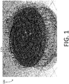
- FIG. 1 illustrates a perspective view of a device 100 according to an example.
- the device 100 may be implemented in connection with a wearable audio device, such as a wireless in-ear headphone configured to be inserted into, or coupled proximate to, a human ear canal.
- the device 100 may be implemented in connection with (for example, housed within) one of the first housing 402, the second housing 404, and the housing 502.
- the device 100 includes a headphone enclosure 102, an antenna 104, and a ground disc 106, or "ground plane.”
- the headphone enclosure 102 is illustrated as partially transparent for purposes of illustration of components of the device 100, including the antenna 104 and the ground disc 106.
- the headphone enclosure 102 is configured to enclose components of the device 100 including, for example, the antenna 104 and the ground disc 106.
- the headphone enclosure 102 may include a material or materials that enable the antenna 104 to be formed on a surface of the headphone enclosure 102, such as laser direct structuring (LDS) materials.
- LDS laser direct structuring
- the headphone enclosure 102 may be formed of a non-conductive material impregnated with a conductive material.
- the antenna 104 may be formed using antenna formation techniques including, for example, LDS or other antenna formation techniques.
- a form factor of the headphone enclosure 102 may be an important feature of the device 100 for users. For example, users may dislike headphones having profiles that extend far outside of the ear canal or the pinna when worn. Such high-profile headphones may be disadvantageously bulky or unaesthetic to users, and may not have a mechanically stable mounting.
- the device 100 may be a low-profile headphone, constructed such that the headphone enclosure 102 does not extend outside of the ear canal or pinna significantly or at all when the device 100, or a device within which the device 100 may be housed, is inserted into a user's ear canal.
- the antenna 104 includes a ring 108, arms 110a-110d, connectors 112a-112d, and an excitation port 116.
- Each of the arms 110a-110d is connected to the ring 108 at a respective first connection, and is connected to a respective connector of the connectors 112a-112d at a respective second connection.
- Each of the connectors 112a-112d is connected to a respective arm of the arms 110a-110d at a first end, and is connected to the ground disc 106 at a respective second end.
- the excitation port 116 may not be connected to the ground disc 106, and may be referenced to ground.
- the excitation port 116 is physically close to the connector 112d such that the connector 112d acts as a shunt inductance for impedance matching.
- the excitation port 116 may be removed, and the connector 112d may instead act as an excitation port.
- the connector 112d may be coupled to ground, but may be referenced to the ground disc 106.
- each of the arms 110a-110d includes a respective first connection configured to be coupled to the ring 108, and a respective second connection configured to be coupled to the ground disc 106.
- the first connections of the arms 110a-110d may be evenly spaced in 90-degree increments about a circumference of the ring 108, and the second connections of the arms 110a-110d may be evenly spaced in 90-degree increments about a circumference of the ground disc 106.
- the second connection of the arm 110a may similarly be coupled (either directly, or via the connector 112a) to a point on the ground disc 106 that is 90 degrees, measured in a counterclockwise arc from a center of the ground disc 106, from a point on the ground disc 106 at which a second connection of the arm 110c is coupled (either directly, or via the connector 112c).
- a second connection of the arm 110b may be coupled to a point on the ground disc 106 that is 90 degrees, measured in a counterclockwise arc from the center of the ground disc 106, from the point on the ground disc 106 at which the second connection of the arm 110a is coupled.
- a radius of the ground disc 106 may differ from a radius of the ring 108 (i.e., a distance in the u-v plane from the center of the ring 108 to any one of the first connections of the arms 110a-110d).
- first connection of the arm 110a may be separated by 90 degrees from the first connection of the arm 110b
- second connection of the arm 110a may be separated by 90 degrees from the second connection of the arm 110b
- an arc length between the first connection of the arm 110a and the first connection of the arm 110b in the u-v plane may be different than (for example, shorter than) an arc length between the second connection of the arm 110a and the second connection of the arm 110b in the u-v plane.
- arms may be added or removed.
- increasing the number of arms may advantageously increase a radiation resistance of the antenna 104 as well as reducing a quality factor.
- the ring 108 is illustrated as being circular, the ring 108 may take another form, such as by being rectangularly shaped.
- the arms 110a-110d are arranged in a roughly spiral arrangement in the u-v plane, the arms 110a-110d may alternately be arranged in a square arrangement, a pentagonal arrangement, a hexagonal arrangement, or other arrangements in the u-v plane. Furthermore, the arms 110a-110d may have a geometry other than the illustrated Archimedean spiral geometry in some examples, and may be spaced regularly or irregularly around the circumference of the ring 108.
- the connectors 112a-112d may include any conductive connectors, such as vertical conducting ports, pogo pins, conducting trace patterns etched on a surface of the enclosure 102, and so forth. In some examples, all of the connectors 112a-112d are connected to the ground disc 106, with an excitation port (for example, the excitation port 116) implemented physically close to one of the connectors 112a-112d to improve impedance matching. In other examples, one of the connectors 112a-112d may be disconnected from the ground disc 106 and may function as an excitation port. For example, the excitation port may be implemented to provide impedance matching as necessary or desired.
- examples of in-ear headphones may be configured to communicate with electrical devices.
- the devices may transmit electromagnetic radiation to, or receive electromagnetic radiation from, the in-ear headphones' antennas, such as the antenna 104.
- the antenna 104 may have a radiation pattern that advantageously reduces the transmit power of the antenna 104 relative to certain conventional linearly polarized antennas.
- the antenna 104 may have a low radiating power in a direction facing into the human body.
- examples of the antenna 104 may minimize such disadvantageous coupling and thereby minimize a total amount of radiation absorbed by the human body.
- At least one example provides an elliptically polarized monopole antenna coupled to a small ground disc. More particularly, a diameter of the ground disc 106 may be approximately equal to a diameter of the antenna 104 to enable the antenna 104 to transmit and receive both horizontally polarized and vertically polarized components of electromagnetic radiation. Although the antenna 104 is able to transmit and receive a vertically polarized component electromagnetic radiation, a profile of the device 100 is sufficiently low that the device 100 does not extend significantly or at all from the ear canal or pinna when in use. Thus, the device 100 may be capable of transmitting and receiving both vertically polarized and horizontally polarized components of electromagnetic radiation without compromising a form factor of the device 100.
- the headphone enclosure 202 is configured to enclose or be otherwise coupled to components of the device 200 including, for example, the antenna 204 and the ground disc 206.
- the headphone enclosure 202 may have a form factor approximated by, for example, a 5 th -order polynomial.
- the headphone enclosure 202 may include a material or materials that enable the antenna 204 to be formed on a surface of the headphone enclosure 202, such as LDS materials.
- the headphone enclosure 202 may be formed of a non-conductive material impregnated with a conductive material.
- the antenna 204 may be formed using antenna fabrication techniques including, for example, LDS or other techniques.
- the headphone enclosure 202 may be an important feature of the device 200 for users. Similar to the device 100, in some examples, the device 200 may be a low-profile headphone, constructed such that the headphone enclosure 202, or a device within which the device 200 may be housed, does not extend outside of the ear canal or pinna significantly or at all when in use.
- the antenna 204 may be elliptically shaped, having a major axis along the u axis and a minor axis along the v axis. In some examples, an eccentricity ratio of the antenna 204 is approximately 1.
- a shape and size of the ground disc 206 may be similar to, or slightly greater than, a shape and size of a w -axis projection of an envelope of the antenna 204.
- the arms 210a-210c include three Archimedean spirals evenly spaced around a circumference of the ring 208 and about a circumference of the ground disc 206.
- the arms 210a-210c may be evenly spaced about a circumference of the ring 208 and the ground disc 206 inasmuch as the arms 210a-210c are symmetrical about any line evenly bisecting the ring 208, and evenly bisecting the ground disc 206.
- each of the arms 210a-210c includes a respective first connection configured to be coupled to the ring 208, and a respective second connection configured to be coupled to the ground disc 206.
- the first connections of the arms 210a-210c may be evenly spaced in 120-degree increments about a circumference of the ring 208, and the second connections of the arms 210a-210c may be evenly spaced in 120-degree increments about a circumference of the ground disc 206.
- a first connection of the arm 210a may be coupled to a point on the ring 208 that is 120 degrees, measured in a counterclockwise arc from a center of the ring 208, from a point on the ring 208 at which a first connection of the arm 210c is coupled.
- a first connection of the arm 210b may be coupled to a point on the ring 208 that is 120 degrees, measured in a counterclockwise arc from the center of the ring 208, from the point on the ring 208 at which the first connection of the arm 210a is coupled.
- the second connection of the arm 210a may similarly be coupled to a point on the ground disc 206 that is 120 degrees, measured in a counterclockwise arc from a center of the ground disc 206, from a point on the ground disc 206 at which a second connection of the arm 210c is coupled.
- a second connection of the arm 210b may be coupled to a point on the ground disc 206 that is 120 degrees, measured in a counterclockwise arc from the center of the ground disc 206, from the point on the ground disc 206 at which the second connection of the arm 210a is coupled.
- the antenna 204 may include an excitation port referenced to ground.
- the excitation port may be physically close to at least one of the connectors 210a-210c such that the at least one connector acts as a shunt inductance for impedance matching.
- no separate excitation port may be implemented, and one of the connectors 210a-210c may instead act as an excitation port.
- the connector acting as an excitation port may be coupled to ground, rather than the ground disc 206, but may be referenced to the ground disc 206.
- a radius of the ground disc 206 may differ from a radius of the ring 208 (i.e., a distance in the u-v plane from the center of the ring 208 to any one of the first connections of the arms 210a-210c).
- first connection of the arm 210a may be separated by 120 degrees from the first connection of the arm 210b
- second connection of the arm 210a may be separated by 120 degrees from the second connection of the arm 210b
- an arc length between the first connection of the arm 210a and the first connection of the arm 210b in the u-v plane may be different than (for example, shorter than) an arc length between the second connection of the arm 210a and the second connection of the arm 210b in the u-v plane.
- arms may be added or removed.
- increasing a number of arms may advantageously increase a radiation resistance of the antenna 204 as well as reducing the quality factor.
- the arms 210a-210c may be arranged in a roughly elliptical arrangement in the u-v plane, the arms 210a-210c may be arranged in a square arrangement, a pentagonal arrangement, a hexagonal arrangement, or other arrangements in the u-v plane. Furthermore, the arms 210a-210c may have a geometry other than the illustrated Archimedean spiral geometry in other examples, and may be separated regularly or irregularly around the circumference of the ring 208.
- examples of the device 200 may provide an elliptically polarized monopole antenna coupled to a small ground disc.
- a diameter of the ground disc 206 may be approximately equal to a diameter of the antenna 204 to enable the antenna 204 to receive both horizontally polarized and vertically polarized components of electromagnetic radiation.
- the antenna 204 is able to receive a vertically polarized component of electromagnetic radiation, a profile of the device 200 is sufficiently low that the device 200 does not extend significantly or at all from the ear canal or pinna when in use.
- the device 200 may be capable of receiving both horizontally polarized and vertically polarized components of electromagnetic radiation without compromising a form factor of the device 200.
- the antenna 204 may have a radiation pattern that advantageously reduces the antenna's 204 transmit power relative to certain conventional linearly polarized antennas.
- the antenna 104 may have a low radiating power in a direction facing into the human body, thereby minimizing a total amount of power absorbed by a user.
- Examples of antennas have been provided having certain numbers of arms, such as three or four arms, evenly spaced around a ring. In other examples, an alternate number of arms may be implemented.
- the arms may be evenly or unevenly spaced around a ring. In an example in which arms are evenly spaced around the ring, the arms may be separated by n degrees, where n is equal to 360 degrees divided by the number of arms. Thus, in an example in which five arms are evenly spaced around the ring, the arms would be evenly spaced every 72 degrees around the circumference of the ring. In examples in which the arms are unevenly spaced around the ring, the arms may be separated by any number of degrees around the ring. In some examples, an elliptical polarization property of an antenna may be maintained where a degree of unevenness is low, or on the order of small perturbations.
- a radius (or major axis, if the antenna 104 is a non-circular ellipse) of the antenna 104 projected onto the u-v plane may be approximately equal to, or slightly less than, a radius of the ground disc 106 in the u-v plane.
- a radii ratio of the device 100 may refer to the radius of the ground disc 106 as defined above divided by the radius of the antenna 104 projected onto the u-v plane.
- a radius of the ground disc 206 may be approximately equal to, or slightly greater than, a radius of the antenna 204 projected onto the u-v plane.
- a radii ratio of the device 200 may refer to the radius of the ground disc 206 as defined above divided by the radius of the antenna 204.
- FIG. 8 illustrates a graph 800 of a radii ratio of each of the devices 100, 200 against an axial ratio of the respective devices 100, 200.
- the radii ratio may refer to a ratio of a radius of one of the ground disc 106, 206 to a radius of one of the antenna 104, 204, respectively.
- the axial ratio refers to the ratio of the vertical to horizontal polarization of the devices 100, 200.
- the greater the radius of the ground discs 106, 206 the greater the vertical polarization of the devices 100, 200.
- wireless audio devices such as headphones
- other examples may include any wireless wearable and/or hearable devices.
- examples may extend beyond audio applications.
- certain examples may be implemented in connection with one or more communication links carrying vital signals of medical devices, such as implanted medical devices.
Landscapes
- Physics & Mathematics (AREA)
- Engineering & Computer Science (AREA)
- Acoustics & Sound (AREA)
- Signal Processing (AREA)
- Details Of Aerials (AREA)
- Headphones And Earphones (AREA)
Abstract
Description
- At least one example in accordance with the present disclosure relates generally to wireless devices, including wireless headphones.
- Wireless headphones may include one or more components to enable wireless communication with an audio source. For example, wireless headphones may include antennas configured to send and receive signals encoding audio information to and from an audio source. In the context of certain wireless in-ear headphones, a form factor of the antenna may be restricted by a need for a headphone to fit partially within a user's ear canal.
- According to one aspect, a wearable audio device is provided including a ground plane, an elliptically polarized spiral monopole antenna configured to be coupled to the ground plane, the antenna comprising a ring, and a plurality of arms, each arm of the plurality of arms being configured to be coupled between the ring and the ground plane, and an enclosure configured to enclose the ground plane, and configured to be coupled to an ear of a user.
- In one example, a radius of the ground plane is approximately equal to a radius of the elliptically polarized monopole antenna. In at least one example, the elliptically polarized monopole antenna is configured to transmit and/or receive a vertically polarized component of electromagnetic radiation and a horizontally polarized component of the electromagnetic radiation. In some examples, one or more arms of the plurality of arms is configured in an Archimedean spiral arrangement.
- In some examples, the arms of the plurality of arms are configured to be evenly spaced around a circumference of the ring. In at least one example, the plurality of arms comprises four arms. In some examples, the device includes a plurality of conducting ports, wherein each arm is configured to be coupled to the ground plane via a respective conducting port of the plurality of conducting ports. In an example, the plurality of arms comprises three arms. In one example, each arm is configured to be coupled directly to the ground plane. In at least one example, the elliptically polarized monopole antenna is configured to be formed on a surface of the enclosure.
- According to aspects of the disclosure, an antenna is provided including a ring, and a plurality of arms, each arm of the plurality of arms having a first connection coupled to the ring, and a second connection configured to be coupled to a ground plane, the plurality of arms being arranged such that the antenna is an elliptically polarized spiral monopole antenna, wherein the antenna is configured to be formed on a surface of an enclosure of a wearable audio device, the enclosure being configured to be coupled to an ear of a user.
- In an example, a radius of the antenna is approximately equal to a radius of the ground plane. In one example, the antenna is configured to transmit and/or receive electromagnetic radiation from a device, and wherein the antenna is configured to transmit and/or receive a vertically polarized component of electromagnetic radiation and a horizontally polarized component of electromagnetic radiation. In at least one example, the plurality of arms is configured in an Archimedean spiral arrangement.
- In one example, wherein the arms of the plurality of arms are configured to be evenly separated around a circumference of the ring and around a circumference of the ground plane. In an example, the plurality of arms comprises four arms. In some examples, each arm is configured to be coupled to the ground plane via a conducting port. In at least one example, the plurality of arms comprises three arms. In one example, each arm is configured to be coupled directly to the ground plane. In an example, the antenna is configured to be formed on the surface of the wearable audio device enclosure.
- Various aspects of at least one example are discussed below with reference to the accompanying figures, which are not intended to be drawn to scale. The figures are included to provide an illustration and a further understanding of the various aspects and examples, and are incorporated in and constitute a part of this specification, but are not intended as a definition of the limits of any particular example. The drawings, together with the remainder of the specification, serve to explain principles and operations of the described and claimed aspects and examples. In the figures, each identical or nearly identical component that is illustrated in various figures is represented by a like numeral. For purposes of clarity, not every component may be labeled in every figure. In the figures:
-
FIG. 1 illustrates a perspective view of a device according to an example; -
FIG. 2 illustrates a perspective view of a device according to another example; -
FIG. 3 illustrates a perspective view of headphones according to an example; -
FIG. 4 illustrates a perspective view of headphones according to another example; -
FIG. 5A illustrates a first perspective view of a headphone according to an example; -
FIG. 5B illustrates a second perspective view of the headphone according to an example; -
FIG. 6A illustrates a side view of a wearable audio device according to an example; -
FIG. 6B illustrates a back view of the wearable audio device according to an example; -
FIG. 7A illustrates a frontal view of a wearable audio device according to an example; -
FIG. 7B illustrates a frontal view of a wearable audio device according to an example; and -
FIG. 8 illustrates a graph of a device radii ratio against a device axial ratio. - Wireless headphone antennas may be designed with a circular or an elliptical (which may be circular or non-circular) polarization along a broadside of the antenna. In an example, an elliptically polarized monopole antenna is coupled to a small ground plane. The diameter of the antenna is approximately equal to the diameter of the ground plane. The antenna may include one or more spiral arms. These spiral arms may include one or more Archimedean spiral arms. One end of each spiral arm may be connected to a ring centered above a ground disc. A second end of the spiral arm may be connected to the ground disc either directly or via a conducting port. The ends of the spiral arms may be evenly separated around a circumference of the ring and the ground plane.
- A circularly or elliptically polarized monopole antenna may be beneficial in a low-profile wearable device that does not extend from a user's ear canal or pinna significantly or at all. The antenna is configured to receive both horizontally or vertically polarized components of electromagnetic radiation propagating along a referenced observation interface, such as the surface of a human body. Furthermore, the antenna may have an advantageously low profile in part due to the monopole, rather than dipole, structure of the antenna, at least because a dipole antenna may have a volume that is approximately twice a volume of a monopole antenna. Thus, an exemplary elliptically polarized monopole antenna may be capable of transmitting and receiving both vertically polarized and horizontally polarized components of electromagnetic radiation without detrimentally impacting a profile of the antenna.
- The examples discussed herein are not limited in application to the details of construction and the arrangement of components set forth in the following description or illustrated in the accompanying drawings. The methods and systems are capable of implementation in other examples and of being practiced or of being carried out in various ways. Examples of specific implementations are provided herein for illustrative purposes only and are not intended to be limiting. In particular, acts, components, elements and features discussed in connection with any one or more examples are not intended to be excluded from a similar role in any other examples.
- Also, the phraseology and terminology used herein is for the purpose of description and should not be regarded as limiting. Any references to examples, components, elements or acts of the systems and methods herein referred to in the singular may also embrace examples including a plurality, and any references in plural to any example, component, element or act herein may also embrace examples including only a singularity. References in the singular or plural form are not intended to limit the presently disclosed systems or methods, their components, acts, or elements. The use herein of "including," "comprising," "having," "containing," "involving," and variations thereof is meant to encompass the items listed thereafter and equivalents thereof as well as additional items.
- References to "or" may be construed as inclusive so that any terms described using "or" may indicate any of a single, more than one, and all of the described terms. In addition, in the event of inconsistent usages of terms between this document and documents incorporated herein by reference, the term usage in the incorporated features is supplementary to that of this document; for irreconcilable differences, the term usage in this document controls.
- A headphone or earphone may refer to a device that typically fits around, on, in, or near an ear and that radiates acoustic energy into or towards the ear canal. Headphones and earphones are sometimes referred to as earpieces, headsets, earbuds, or sport headphones, and can be wired or wireless. Certain wireless headphones play audio to a user based on information received from an audio source. An audio source may include a computing device (for example, a laptop computer, desktop computer, tablet, smartphone, or other electronic device) configured to communicate wireless signals encoding audio information to the wireless headphones. While headphones are described in various examples within this document, the technology described in this document is also applicable to other wearable audio devices. The term "wearable audio device," as used in this document, is intended to mean a device that fits around, on, in, or near an ear (including open-ear audio devices worn on the head or shoulders of a user) and that radiates acoustic energy into or towards the ear. Wearable audio devices include but are not limited to headphones, earphones, earpieces, headsets, earbuds, sport headphones, and audio eyeglasses, and can be wired or wireless. In some examples, a wearable audio device may be an open-ear device that includes an acoustic driver to radiate acoustic energy towards the ear while leaving the ear open to its environment and surroundings.
- A headphone may include an electro-acoustic transducer driver to transduce audio signals into acoustic energy. The acoustic driver may be housed in an earcup, earbud, or other housing. Some of the figures and descriptions following show a single headphone device. A headphone may be a single stand-alone unit or one of a pair of headphones (each including at least one acoustic driver), one for each ear. A headphone may be connected mechanically and/or electrically to another headphone, for example by a headband and/or by leads that conduct audio signals to an acoustic driver in the headphone. A headphone may include components for wirelessly receiving audio signals. A headphone may include components of an active noise reduction (ANR) system. Headphones may also include other components, such as microphones, accelerometers, gyroscopes, infrared sensors, compasses, and so forth. A headphone may also be an open-ear device that includes an electro-acoustic transducer to radiate acoustic energy towards the ear canal while leaving the ear open to its environment and surroundings.
- Exemplary headphones will be described.
FIG. 3 illustrates a perspective view ofheadphones 300 according to an example. Theheadphones 300 include afirst housing 302, asecond housing 304, and aconnector 306. In one example, thefirst housing 302 may be configured to be placed over one of a user's ears, and thesecond housing 304 may be configured to be placed over another of the user's ears. Thefirst housing 302 and thesecond housing 304 may each respectively include an acoustic driver configured to transmit acoustic energy to the user. Theconnector 306 may provide an electrical and/or mechanical connection between thefirst housing 302 and thesecond housing 304 and facilitate coupling of theheadphones 300 to the user's ears and/or head. -
FIG. 4 illustrates a perspective view ofheadphones 400 according to another example. Theheadphones 400 include afirst housing 402, asecond housing 404, and aconnector 406. In one example, thefirst housing 402 may be configured to be inserted into one of a user's ear canals or pinne, and thesecond housing 304 may be configured to be inserted into another of the user's ear canals or pinne. Thefirst housing 402 and thesecond housing 404 may each respectively include an acoustic driver configured to provide acoustic energy to the user. Theconnector 406 may provide an electrical and/or mechanical connection between thefirst housing 402 and thesecond housing 404. -
FIG. 5A illustrates a perspective view of aheadphone 500 according to another example.FIG. 5B illustrates another perspective view of theheadphone 500 according to an example. Theheadphone 500 includes ahousing 502. In one example, thehousing 502 may be configured to be inserted into one of a user's ear canals or pinne. Thehousing 502 may include an acoustic driver configured to provide acoustic energy to the user. Theheadphone 500 may be implemented in conjunction with another, similar, headphone configured to be inserted into another of the user's ear canals or pinne. In some examples, theheadphone 500 and the similar headphone may communicate wirelessly with one another. - Wireless headphones may include one or more antennas. Antennas can convert electromagnetic waves propagating through space into electrical currents. Certain antenna properties may be affected by a form factor of the antenna. For example, the form factor of an antenna may dictate radiation behavior (for example, a radiation pattern), polarization, efficiency, and configuration options.
- A form factor of the antenna may also dictate how the antenna is implemented. As used herein, a "profile" refers to an extent to which an in-ear headphone extends out of the ear canal or pinna. A low-profile antenna or headphone may refer to an antenna or headphone that does not extend significantly, or at all, out of a user's ear canal or pinna when in use. A high-profile antenna or headphone, in contrast, may refer to an antenna or headphone that extends significantly from the ear canal or pinna. Some users may prefer low-profile antennas over high-profile antennas, because such users may consider low-profile antennas to be more comfortable or aesthetic, and because high-profile antennas may have a less mechanically stable mounting.
- For example,
FIG. 6A illustrates a side view of awearable audio device 600 coupled to anear 602 of a user.FIG. 6B illustrated a back view of thewearable audio device 600 coupled to theear 602 of the user. As illustrated byFIG. 6B , thewearable audio device 600 does not extend far enough out of theear 602 of the user to be visible behind theear 602. Thewearable audio device 600 may thus be considered to be a low-profile wearable audio device, at least because thewearable audio 600 device does not extend significantly out of theear 602. - In another example,
FIG. 7A illustrates a frontal view of awearable audio device 700 coupled to anear 702 of a user.FIG. 7B illustrates a frontal view of a wearable audio device 750 coupled to theear 702 of the user. As illustrated byFIGS. 7A and 7B , thewearable audio device 700 extends farther out from theear 702 of the user than the wearable audio device 750. Thewearable audio device 700 may thus be considered to have a higher profile than the wearable audio device 750. - Elliptically polarized antennas capable of receiving both horizontally and vertically polarized components of electromagnetic radiation may be advantageous for headphones, including low profile headphones. Headphones described herein are capable of receiving both vertically polarized and horizontally polarized components of electromagnetic radiation while maintaining a low profile. Although other implementations are contemplated, some examples include an elliptically polarized monopole antenna. A ground plane to which the monopole antenna is coupled may have a diameter that is roughly equivalent to a diameter of the antenna. Thus, examples of headphones are provided in which the headphones include antennas capable of receiving both vertically polarized and horizontally polarized components of electromagnetic radiation, and mitigate disadvantages associated with vertically polarized antennas' high-profile form factors.
-
FIG. 1 illustrates a perspective view of adevice 100 according to an example. Thedevice 100 may be implemented in connection with a wearable audio device, such as a wireless in-ear headphone configured to be inserted into, or coupled proximate to, a human ear canal. For example, thedevice 100 may be implemented in connection with (for example, housed within) one of thefirst housing 402, thesecond housing 404, and thehousing 502. Thedevice 100 includes aheadphone enclosure 102, anantenna 104, and aground disc 106, or "ground plane." Theheadphone enclosure 102 is illustrated as partially transparent for purposes of illustration of components of thedevice 100, including theantenna 104 and theground disc 106. - The
headphone enclosure 102 is configured to enclose components of thedevice 100 including, for example, theantenna 104 and theground disc 106. Theheadphone enclosure 102 may include a material or materials that enable theantenna 104 to be formed on a surface of theheadphone enclosure 102, such as laser direct structuring (LDS) materials. For example, theheadphone enclosure 102 may be formed of a non-conductive material impregnated with a conductive material. Theantenna 104 may be formed using antenna formation techniques including, for example, LDS or other antenna formation techniques. - As discussed above, a form factor of the
headphone enclosure 102 may be an important feature of thedevice 100 for users. For example, users may dislike headphones having profiles that extend far outside of the ear canal or the pinna when worn. Such high-profile headphones may be disadvantageously bulky or unaesthetic to users, and may not have a mechanically stable mounting. In some examples, thedevice 100 may be a low-profile headphone, constructed such that theheadphone enclosure 102 does not extend outside of the ear canal or pinna significantly or at all when thedevice 100, or a device within which thedevice 100 may be housed, is inserted into a user's ear canal. - The
antenna 104 includes a ring 108,arms 110a-110d,connectors 112a-112d, and an excitation port 116. Each of thearms 110a-110d is connected to the ring 108 at a respective first connection, and is connected to a respective connector of theconnectors 112a-112d at a respective second connection. Each of theconnectors 112a-112d is connected to a respective arm of thearms 110a-110d at a first end, and is connected to theground disc 106 at a respective second end. - The excitation port 116 may not be connected to the
ground disc 106, and may be referenced to ground. In a first example, the excitation port 116 is physically close to the connector 112d such that the connector 112d acts as a shunt inductance for impedance matching. In a second example, the excitation port 116 may be removed, and the connector 112d may instead act as an excitation port. In the second example, the connector 112d may be coupled to ground, but may be referenced to theground disc 106. - In an example, the
antenna 104 is elliptically polarized. For purposes of the following example, properties of thedevice 100 are discussed with respect to the u, v, and w axes indicated by the axis legend 114. In one example, theantenna 104 has an axial ratio of approximately 3 dB, such that a radiation pattern is predominantly vertically polarized. - In one example, the
arms 110a-110d include four Archimedean spirals evenly spaced about a circumference of the ring 108 and about a circumference of theground disc 106. Thearms 110a-110d are evenly spaced about a circumference of the ring 108 and theground disc 106 inasmuch as thearms 110a-110d are symmetrical about any line evenly bisecting the ring 108, and evenly bisecting theground disc 106. - In one example, each of the
arms 110a-110d includes a respective first connection configured to be coupled to the ring 108, and a respective second connection configured to be coupled to theground disc 106. The first connections of thearms 110a-110d may be evenly spaced in 90-degree increments about a circumference of the ring 108, and the second connections of thearms 110a-110d may be evenly spaced in 90-degree increments about a circumference of theground disc 106. - For example, a first connection of the
arm 110a may be coupled to a point on the ring 108 that is 90 degrees, measured in a counterclockwise arc from a center of the ring 108, from a point on the ring 108 at which a first connection of thearm 110c is coupled. Similarly, a first connection of thearm 110b may be coupled to a point on the ring 108 that is 90 degrees, measured in a counterclockwise arc from the center of the ring 108, from the point on the ring 108 at which the first connection of thearm 110a is coupled. - The second connection of the
arm 110a may similarly be coupled (either directly, or via theconnector 112a) to a point on theground disc 106 that is 90 degrees, measured in a counterclockwise arc from a center of theground disc 106, from a point on theground disc 106 at which a second connection of thearm 110c is coupled (either directly, or via theconnector 112c). Similarly, a second connection of thearm 110b may be coupled to a point on theground disc 106 that is 90 degrees, measured in a counterclockwise arc from the center of theground disc 106, from the point on theground disc 106 at which the second connection of thearm 110a is coupled. - A radius of the
ground disc 106 may differ from a radius of the ring 108 (i.e., a distance in the u-v plane from the center of the ring 108 to any one of the first connections of thearms 110a-110d). Thus, while the first connection of thearm 110a may be separated by 90 degrees from the first connection of thearm 110b, and the second connection of thearm 110a may be separated by 90 degrees from the second connection of thearm 110b, an arc length between the first connection of thearm 110a and the first connection of thearm 110b in the u-v plane may be different than (for example, shorter than) an arc length between the second connection of thearm 110a and the second connection of thearm 110b in the u-v plane. - In other examples, arms may be added or removed. For example, increasing the number of arms may advantageously increase a radiation resistance of the
antenna 104 as well as reducing a quality factor. Furthermore, although the ring 108 is illustrated as being circular, the ring 108 may take another form, such as by being rectangularly shaped. - Although the
arms 110a-110d are arranged in a roughly spiral arrangement in the u-v plane, thearms 110a-110d may alternately be arranged in a square arrangement, a pentagonal arrangement, a hexagonal arrangement, or other arrangements in the u-v plane. Furthermore, thearms 110a-110d may have a geometry other than the illustrated Archimedean spiral geometry in some examples, and may be spaced regularly or irregularly around the circumference of the ring 108. - The
connectors 112a-112d may include any conductive connectors, such as vertical conducting ports, pogo pins, conducting trace patterns etched on a surface of theenclosure 102, and so forth. In some examples, all of theconnectors 112a-112d are connected to theground disc 106, with an excitation port (for example, the excitation port 116) implemented physically close to one of theconnectors 112a-112d to improve impedance matching. In other examples, one of theconnectors 112a-112d may be disconnected from theground disc 106 and may function as an excitation port. For example, the excitation port may be implemented to provide impedance matching as necessary or desired. - As discussed above, examples of in-ear headphones may be configured to communicate with electrical devices. For example, the devices may transmit electromagnetic radiation to, or receive electromagnetic radiation from, the in-ear headphones' antennas, such as the
antenna 104. In some examples, theantenna 104 may have a radiation pattern that advantageously reduces the transmit power of theantenna 104 relative to certain conventional linearly polarized antennas. For example, theantenna 104 may have a low radiating power in a direction facing into the human body. Thus, unlike certain conventional linearly polarized antennas, which couple a significant amount of radiation into the human body, examples of theantenna 104 may minimize such disadvantageous coupling and thereby minimize a total amount of radiation absorbed by the human body. - Thus, at least one example provides an elliptically polarized monopole antenna coupled to a small ground disc. More particularly, a diameter of the
ground disc 106 may be approximately equal to a diameter of theantenna 104 to enable theantenna 104 to transmit and receive both horizontally polarized and vertically polarized components of electromagnetic radiation. Although theantenna 104 is able to transmit and receive a vertically polarized component electromagnetic radiation, a profile of thedevice 100 is sufficiently low that thedevice 100 does not extend significantly or at all from the ear canal or pinna when in use. Thus, thedevice 100 may be capable of transmitting and receiving both vertically polarized and horizontally polarized components of electromagnetic radiation without compromising a form factor of thedevice 100. -
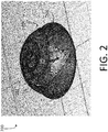
FIG. 2 illustrates a perspective view of adevice 200 according to another example. Thedevice 200 may be implemented in connection with a wearable audio device, such as a wireless in-ear headphone configured to be inserted into, or proximate to, a human ear canal. For example, thedevice 200 may be implemented in connection with (for example, housed within) one of thefirst housing 402, thesecond housing 404, and thehousing 502. Thedevice 200 includes aheadphone enclosure 202, anantenna 204, and aground disc 206, or ground plane. - The
headphone enclosure 202 is configured to enclose or be otherwise coupled to components of thedevice 200 including, for example, theantenna 204 and theground disc 206. Theheadphone enclosure 202 may have a form factor approximated by, for example, a 5th-order polynomial. Theheadphone enclosure 202 may include a material or materials that enable theantenna 204 to be formed on a surface of theheadphone enclosure 202, such as LDS materials. For example, theheadphone enclosure 202 may be formed of a non-conductive material impregnated with a conductive material. Theantenna 204 may be formed using antenna fabrication techniques including, for example, LDS or other techniques. - As discussed above, a form factor of the
headphone enclosure 202 may be an important feature of thedevice 200 for users. Similar to thedevice 100, in some examples, thedevice 200 may be a low-profile headphone, constructed such that theheadphone enclosure 202, or a device within which thedevice 200 may be housed, does not extend outside of the ear canal or pinna significantly or at all when in use. - The
antenna 204 includes aring 208 andarms 210a-210c. Each of thearms 210a-210c is connected to thering 208 at a respective first connection and is connected to theground disc 206 at a respective second connection. In an example, theantenna 204 is elliptically polarized. For purposes of the following example, properties of thedevice 200 are discussed with respect to the u, v, and w axes indicated by theaxis legend 212. - The
antenna 204 may be elliptically shaped, having a major axis along the u axis and a minor axis along the v axis. In some examples, an eccentricity ratio of theantenna 204 is approximately 1. A shape and size of theground disc 206 may be similar to, or slightly greater than, a shape and size of a w-axis projection of an envelope of theantenna 204. - In one example, the
arms 210a-210c include three Archimedean spirals evenly spaced around a circumference of thering 208 and about a circumference of theground disc 206. Thearms 210a-210c may be evenly spaced about a circumference of thering 208 and theground disc 206 inasmuch as thearms 210a-210c are symmetrical about any line evenly bisecting thering 208, and evenly bisecting theground disc 206. - As discussed above, each of the
arms 210a-210c includes a respective first connection configured to be coupled to thering 208, and a respective second connection configured to be coupled to theground disc 206. The first connections of thearms 210a-210c may be evenly spaced in 120-degree increments about a circumference of thering 208, and the second connections of thearms 210a-210c may be evenly spaced in 120-degree increments about a circumference of theground disc 206. - For example, a first connection of the
arm 210a may be coupled to a point on thering 208 that is 120 degrees, measured in a counterclockwise arc from a center of thering 208, from a point on thering 208 at which a first connection of thearm 210c is coupled. Similarly, a first connection of thearm 210b may be coupled to a point on thering 208 that is 120 degrees, measured in a counterclockwise arc from the center of thering 208, from the point on thering 208 at which the first connection of thearm 210a is coupled. - The second connection of the
arm 210a may similarly be coupled to a point on theground disc 206 that is 120 degrees, measured in a counterclockwise arc from a center of theground disc 206, from a point on theground disc 206 at which a second connection of thearm 210c is coupled. Similarly, a second connection of thearm 210b may be coupled to a point on theground disc 206 that is 120 degrees, measured in a counterclockwise arc from the center of theground disc 206, from the point on theground disc 206 at which the second connection of thearm 210a is coupled. - In some examples, the
antenna 204 may include an excitation port referenced to ground. In a first example, the excitation port may be physically close to at least one of theconnectors 210a-210c such that the at least one connector acts as a shunt inductance for impedance matching. In a second example, no separate excitation port may be implemented, and one of theconnectors 210a-210c may instead act as an excitation port. In the second example, the connector acting as an excitation port may be coupled to ground, rather than theground disc 206, but may be referenced to theground disc 206. - A radius of the
ground disc 206 may differ from a radius of the ring 208 (i.e., a distance in the u-v plane from the center of thering 208 to any one of the first connections of thearms 210a-210c). Thus, while the first connection of thearm 210a may be separated by 120 degrees from the first connection of thearm 210b, and the second connection of thearm 210a may be separated by 120 degrees from the second connection of thearm 210b, an arc length between the first connection of thearm 210a and the first connection of thearm 210b in the u-v plane may be different than (for example, shorter than) an arc length between the second connection of thearm 210a and the second connection of thearm 210b in the u-v plane. - In other examples, arms may be added or removed. For example, increasing a number of arms may advantageously increase a radiation resistance of the
antenna 204 as well as reducing the quality factor. - Although the
arms 210a-210c may be arranged in a roughly elliptical arrangement in the u-v plane, thearms 210a-210c may be arranged in a square arrangement, a pentagonal arrangement, a hexagonal arrangement, or other arrangements in the u-v plane. Furthermore, thearms 210a-210c may have a geometry other than the illustrated Archimedean spiral geometry in other examples, and may be separated regularly or irregularly around the circumference of thering 208. - Thus, similar to examples of the
device 100, examples of thedevice 200 may provide an elliptically polarized monopole antenna coupled to a small ground disc. A diameter of theground disc 206 may be approximately equal to a diameter of theantenna 204 to enable theantenna 204 to receive both horizontally polarized and vertically polarized components of electromagnetic radiation. Although theantenna 204 is able to receive a vertically polarized component of electromagnetic radiation, a profile of thedevice 200 is sufficiently low that thedevice 200 does not extend significantly or at all from the ear canal or pinna when in use. Thus, thedevice 200 may be capable of receiving both horizontally polarized and vertically polarized components of electromagnetic radiation without compromising a form factor of thedevice 200. - Similar to the
antenna 104, theantenna 204 may have a radiation pattern that advantageously reduces the antenna's 204 transmit power relative to certain conventional linearly polarized antennas. For example, theantenna 104 may have a low radiating power in a direction facing into the human body, thereby minimizing a total amount of power absorbed by a user. - Examples of antennas have been provided having certain numbers of arms, such as three or four arms, evenly spaced around a ring. In other examples, an alternate number of arms may be implemented. The arms may be evenly or unevenly spaced around a ring. In an example in which arms are evenly spaced around the ring, the arms may be separated by n degrees, where n is equal to 360 degrees divided by the number of arms. Thus, in an example in which five arms are evenly spaced around the ring, the arms would be evenly spaced every 72 degrees around the circumference of the ring. In examples in which the arms are unevenly spaced around the ring, the arms may be separated by any number of degrees around the ring. In some examples, an elliptical polarization property of an antenna may be maintained where a degree of unevenness is low, or on the order of small perturbations.
- As discussed above, a radius (or major axis, if the
antenna 104 is a non-circular ellipse) of theantenna 104 projected onto the u-v plane may be approximately equal to, or slightly less than, a radius of theground disc 106 in the u-v plane. A radii ratio of thedevice 100 may refer to the radius of theground disc 106 as defined above divided by the radius of theantenna 104 projected onto the u-v plane. - Similarly, a radius of the
ground disc 206 may be approximately equal to, or slightly greater than, a radius of theantenna 204 projected onto the u-v plane. A radii ratio of thedevice 200 may refer to the radius of theground disc 206 as defined above divided by the radius of theantenna 204. - In other examples, other radii ratios may be implemented.
FIG. 8 illustrates agraph 800 of a radii ratio of each of thedevices respective devices ground disc antenna devices ground discs devices - Although certain examples are provided as related to wireless audio devices, such as headphones, other examples may include any wireless wearable and/or hearable devices. Furthermore, examples may extend beyond audio applications. For example, certain examples may be implemented in connection with one or more communication links carrying vital signals of medical devices, such as implanted medical devices.
- Having thus described several aspects of at least one example, it is to be appreciated various alterations, modifications, and improvements will readily occur to those skilled in the art. Such alterations, modifications, and improvements are intended to be part of, and within the spirit and scope of, this disclosure. Accordingly, the foregoing description and drawings are by way of example only.
Claims (11)
- A wearable audio device comprising:a ground plane;an elliptically polarized spiral monopole antenna configured to be coupled to the ground plane, the antenna comprising:a ring; anda plurality of arms, each arm of the plurality of arms being configured to be coupled between the ring and the ground plane; andan enclosure configured to enclose the ground plane, and configured to be coupled to an ear of a user.
- The wearable audio device of claim 1, wherein a radius of the ground plane is approximately equal to a radius of the elliptically polarized monopole antenna.
- The wearable audio device of claim 2, wherein the elliptically polarized monopole antenna is configured to transmit and/or receive a vertically polarized component of electromagnetic radiation and a horizontally polarized component of the electromagnetic radiation.
- The wearable audio device of claim 1, wherein one or more arms of the plurality of arms is configured in an Archimedean spiral arrangement.
- The wearable audio device of claim 4, wherein the arms of the plurality of arms are configured to be evenly spaced around a circumference of the ring.
- The wearable audio device of claim 1, wherein the plurality of arms comprises four arms.
- The wearable audio device of claim 1, further comprising a plurality of conducting ports, wherein each arm is configured to be coupled to the ground plane via a respective conducting port of the plurality of conducting ports.
- The wearable audio device of claim 1, wherein the plurality of arms comprises three arms.
- The wearable audio device of claim 1, wherein each arm is configured to be coupled directly to the ground plane.
- The wearable audio device of claim 1, wherein the elliptically polarized monopole antenna is configured to be formed on a surface of the enclosure.
- An antenna comprising:a ring; anda plurality of arms, each arm of the plurality of arms having a first connection coupled to the ring, and a second connection configured to be coupled to a ground plane, the plurality of arms being arranged such that the antenna is an elliptically polarized spiral monopole antenna,
wherein the antenna is configured to be formed on a surface of an enclosure of a wearable audio device, the enclosure being configured to be coupled to an ear of a user.
Applications Claiming Priority (1)
| Application Number | Priority Date | Filing Date | Title |
|---|---|---|---|
| US16/389,240 US10944157B2 (en) | 2019-04-19 | 2019-04-19 | Multi-arm spiral antenna for a wireless device |
Publications (2)
| Publication Number | Publication Date |
|---|---|
| EP3726650A1 true EP3726650A1 (en) | 2020-10-21 |
| EP3726650B1 EP3726650B1 (en) | 2023-09-13 |
Family
ID=70008286
Family Applications (1)
| Application Number | Title | Priority Date | Filing Date |
|---|---|---|---|
| EP20165519.8A Active EP3726650B1 (en) | 2019-04-19 | 2020-03-25 | Multi-arm spiral antenna for a wireless device |
Country Status (2)
| Country | Link |
|---|---|
| US (1) | US10944157B2 (en) |
| EP (1) | EP3726650B1 (en) |
Cited By (1)
| Publication number | Priority date | Publication date | Assignee | Title |
|---|---|---|---|---|
| US11469489B2 (en) * | 2020-04-28 | 2022-10-11 | Bose Corporation | Antenna operable in single-ended and differential modes |
Families Citing this family (6)
| Publication number | Priority date | Publication date | Assignee | Title |
|---|---|---|---|---|
| CN113243061A (en) * | 2019-11-22 | 2021-08-10 | 歌尔科技有限公司 | Antenna, wireless earplug and electronic device |
| US11525703B2 (en) | 2020-03-02 | 2022-12-13 | Bose Corporation | Integrated capacitor and antenna |
| USD937777S1 (en) * | 2020-06-01 | 2021-12-07 | Sergey Sheleg | Double-negative metamaterial unit cell |
| US11336975B1 (en) * | 2021-02-01 | 2022-05-17 | Shure Acquisition Holdings, Inc. | Wearable device with detune-resilient antenna |
| DE102022203528A1 (en) * | 2022-04-07 | 2023-10-12 | Sivantos Pte. Ltd. | Hearing aid, especially in-the-ear hearing aid |
| US20240204390A1 (en) * | 2022-12-16 | 2024-06-20 | Tyco Electronics Amp Korea Co., Ltd. | Antenna assembly for a wireless ear computer |
Citations (3)
| Publication number | Priority date | Publication date | Assignee | Title |
|---|---|---|---|---|
| US20040108966A1 (en) * | 2002-12-09 | 2004-06-10 | Centurion Wireless Technologies, Inc. | Low Profile Tri-Filar, Single Feed, Circularly Polarized Helical Antenna |
| US20050266875A1 (en) * | 2004-05-26 | 2005-12-01 | Korkut Yegin | Integrated SDARS headphone system |
| EP1833116A2 (en) * | 2004-05-26 | 2007-09-12 | Delphi Technologies, Inc. | Quadrifilar helical antenna |
Family Cites Families (11)
| Publication number | Priority date | Publication date | Assignee | Title |
|---|---|---|---|---|
| US4366483A (en) | 1980-11-03 | 1982-12-28 | General Dynamics, Pomona Division | Receiver and method for use with a four-arm spiral antenna |
| US5220340A (en) * | 1992-04-29 | 1993-06-15 | Lotfollah Shafai | Directional switched beam antenna |
| DE19929879A1 (en) | 1999-06-29 | 2001-01-18 | Bosch Gmbh Robert | Spiral antenna |
| US6646621B1 (en) | 2002-04-25 | 2003-11-11 | Harris Corporation | Spiral wound, series fed, array antenna |
| US7075500B2 (en) | 2004-09-24 | 2006-07-11 | Avocent California Corporation | Antenna for wireless KVM, and housing therefor |
| US7652628B2 (en) * | 2008-03-13 | 2010-01-26 | Sony Ericsson Mobile Communications Ab | Antenna for use in earphone and earphone with integrated antenna |
| US8745853B2 (en) * | 2010-07-05 | 2014-06-10 | Universal Display Corporation | Antenna fabrication with three-dimensional contoured substrates |
| GB201012923D0 (en) * | 2010-07-30 | 2010-09-15 | Sarantel Ltd | An antenna |
| US9065176B2 (en) | 2011-03-30 | 2015-06-23 | Wang-Electro-Opto Corporation | Ultra-wideband conformal low-profile four-arm unidirectional traveling-wave antenna with a simple feed |
| CN106331928B (en) * | 2016-09-13 | 2019-04-23 | 富士高实业有限公司 | pure wireless earphone with ground reflector |
| US10347976B2 (en) * | 2016-12-09 | 2019-07-09 | University Of Idaho | Stacked printed circuit board implementations of three dimensional antennas |
-
2019
- 2019-04-19 US US16/389,240 patent/US10944157B2/en active Active
-
2020
- 2020-03-25 EP EP20165519.8A patent/EP3726650B1/en active Active
Patent Citations (3)
| Publication number | Priority date | Publication date | Assignee | Title |
|---|---|---|---|---|
| US20040108966A1 (en) * | 2002-12-09 | 2004-06-10 | Centurion Wireless Technologies, Inc. | Low Profile Tri-Filar, Single Feed, Circularly Polarized Helical Antenna |
| US20050266875A1 (en) * | 2004-05-26 | 2005-12-01 | Korkut Yegin | Integrated SDARS headphone system |
| EP1833116A2 (en) * | 2004-05-26 | 2007-09-12 | Delphi Technologies, Inc. | Quadrifilar helical antenna |
Cited By (1)
| Publication number | Priority date | Publication date | Assignee | Title |
|---|---|---|---|---|
| US11469489B2 (en) * | 2020-04-28 | 2022-10-11 | Bose Corporation | Antenna operable in single-ended and differential modes |
Also Published As
| Publication number | Publication date |
|---|---|
| US10944157B2 (en) | 2021-03-09 |
| US20200335855A1 (en) | 2020-10-22 |
| EP3726650B1 (en) | 2023-09-13 |
Similar Documents
| Publication | Publication Date | Title |
|---|---|---|
| EP3726650B1 (en) | Multi-arm spiral antenna for a wireless device | |
| US20250175727A1 (en) | In-ear headphone | |
| US11546683B2 (en) | Acoustic output device | |
| US9866946B2 (en) | Wireless headset | |
| CN102570000B (en) | Antenna systems for hearing aids | |
| EP2723101B1 (en) | Bte hearing aid having a balanced antenna | |
| JP6762966B2 (en) | Hearing aid with compound antenna | |
| JP5868900B2 (en) | Antenna system for wearable computer equipment | |
| CN105792049B (en) | Pure wireless earphone adopting optimal monopole antenna | |
| EP3466114B1 (en) | Acoustic device to be worn on the body | |
| EP3324643A1 (en) | Pure wireless earphone having ground plane reflector | |
| JP2884017B2 (en) | Personal hands-free communication device and method of providing directional sound to user of communication device | |
| JP2019500780A (en) | Ear hole type hearing aid with improved wireless communication | |
| CN115442714A (en) | Wireless Headphones | |
| JP2019500826A (en) | Hearing aid with antenna on printed circuit board | |
| US11362428B2 (en) | Multi-band slot antenna | |
| CN115377663A (en) | Wireless earphone | |
| CN216291383U (en) | A bluetooth headset | |
| WO2021067254A1 (en) | Antenna designs for hearing instruments | |
| WO2020087676A1 (en) | Wireless double-earpiece headset | |
| WO2024060006A1 (en) | Earphone and transducer thereof | |
| US20240030592A1 (en) | Antenna designs for hearing instruments | |
| CN222235018U (en) | Open earphone | |
| EP4510381A1 (en) | Inverted f-shaped antenna for hearing instruments | |
| EP4593416A1 (en) | Clip-on earbud |
Legal Events
| Date | Code | Title | Description |
|---|---|---|---|
| PUAI | Public reference made under article 153(3) epc to a published international application that has entered the european phase |
Free format text: ORIGINAL CODE: 0009012 |
|
| STAA | Information on the status of an ep patent application or granted ep patent |
Free format text: STATUS: THE APPLICATION HAS BEEN PUBLISHED |
|
| AK | Designated contracting states |
Kind code of ref document: A1 Designated state(s): AL AT BE BG CH CY CZ DE DK EE ES FI FR GB GR HR HU IE IS IT LI LT LU LV MC MK MT NL NO PL PT RO RS SE SI SK SM TR |
|
| AX | Request for extension of the european patent |
Extension state: BA ME |
|
| STAA | Information on the status of an ep patent application or granted ep patent |
Free format text: STATUS: REQUEST FOR EXAMINATION WAS MADE |
|
| 17P | Request for examination filed |
Effective date: 20210205 |
|
| RBV | Designated contracting states (corrected) |
Designated state(s): AL AT BE BG CH CY CZ DE DK EE ES FI FR GB GR HR HU IE IS IT LI LT LU LV MC MK MT NL NO PL PT RO RS SE SI SK SM TR |
|
| STAA | Information on the status of an ep patent application or granted ep patent |
Free format text: STATUS: EXAMINATION IS IN PROGRESS |
|
| 17Q | First examination report despatched |
Effective date: 20230102 |
|
| GRAP | Despatch of communication of intention to grant a patent |
Free format text: ORIGINAL CODE: EPIDOSNIGR1 |
|
| STAA | Information on the status of an ep patent application or granted ep patent |
Free format text: STATUS: GRANT OF PATENT IS INTENDED |
|
| INTG | Intention to grant announced |
Effective date: 20230605 |
|
| RAP3 | Party data changed (applicant data changed or rights of an application transferred) |
Owner name: BOSE CORPORATION |
|
| GRAS | Grant fee paid |
Free format text: ORIGINAL CODE: EPIDOSNIGR3 |
|
| GRAA | (expected) grant |
Free format text: ORIGINAL CODE: 0009210 |
|
| STAA | Information on the status of an ep patent application or granted ep patent |
Free format text: STATUS: THE PATENT HAS BEEN GRANTED |
|
| AK | Designated contracting states |
Kind code of ref document: B1 Designated state(s): AL AT BE BG CH CY CZ DE DK EE ES FI FR GB GR HR HU IE IS IT LI LT LU LV MC MK MT NL NO PL PT RO RS SE SI SK SM TR |
|
| REG | Reference to a national code |
Ref country code: CH Ref legal event code: EP |
|
| REG | Reference to a national code |
Ref country code: DE Ref legal event code: R096 Ref document number: 602020017490 Country of ref document: DE |
|
| REG | Reference to a national code |
Ref country code: IE Ref legal event code: FG4D |
|
| REG | Reference to a national code |
Ref country code: LT Ref legal event code: MG9D |
|
| REG | Reference to a national code |
Ref country code: NL Ref legal event code: MP Effective date: 20230913 |
|
| PG25 | Lapsed in a contracting state [announced via postgrant information from national office to epo] |
Ref country code: GR Free format text: LAPSE BECAUSE OF FAILURE TO SUBMIT A TRANSLATION OF THE DESCRIPTION OR TO PAY THE FEE WITHIN THE PRESCRIBED TIME-LIMIT Effective date: 20231214 |
|
| PG25 | Lapsed in a contracting state [announced via postgrant information from national office to epo] |
Ref country code: SE Free format text: LAPSE BECAUSE OF FAILURE TO SUBMIT A TRANSLATION OF THE DESCRIPTION OR TO PAY THE FEE WITHIN THE PRESCRIBED TIME-LIMIT Effective date: 20230913 Ref country code: RS Free format text: LAPSE BECAUSE OF FAILURE TO SUBMIT A TRANSLATION OF THE DESCRIPTION OR TO PAY THE FEE WITHIN THE PRESCRIBED TIME-LIMIT Effective date: 20230913 Ref country code: NO Free format text: LAPSE BECAUSE OF FAILURE TO SUBMIT A TRANSLATION OF THE DESCRIPTION OR TO PAY THE FEE WITHIN THE PRESCRIBED TIME-LIMIT Effective date: 20231213 Ref country code: LV Free format text: LAPSE BECAUSE OF FAILURE TO SUBMIT A TRANSLATION OF THE DESCRIPTION OR TO PAY THE FEE WITHIN THE PRESCRIBED TIME-LIMIT Effective date: 20230913 Ref country code: LT Free format text: LAPSE BECAUSE OF FAILURE TO SUBMIT A TRANSLATION OF THE DESCRIPTION OR TO PAY THE FEE WITHIN THE PRESCRIBED TIME-LIMIT Effective date: 20230913 Ref country code: HR Free format text: LAPSE BECAUSE OF FAILURE TO SUBMIT A TRANSLATION OF THE DESCRIPTION OR TO PAY THE FEE WITHIN THE PRESCRIBED TIME-LIMIT Effective date: 20230913 Ref country code: GR Free format text: LAPSE BECAUSE OF FAILURE TO SUBMIT A TRANSLATION OF THE DESCRIPTION OR TO PAY THE FEE WITHIN THE PRESCRIBED TIME-LIMIT Effective date: 20231214 Ref country code: FI Free format text: LAPSE BECAUSE OF FAILURE TO SUBMIT A TRANSLATION OF THE DESCRIPTION OR TO PAY THE FEE WITHIN THE PRESCRIBED TIME-LIMIT Effective date: 20230913 |
|
| REG | Reference to a national code |
Ref country code: AT Ref legal event code: MK05 Ref document number: 1612241 Country of ref document: AT Kind code of ref document: T Effective date: 20230913 |
|
| PG25 | Lapsed in a contracting state [announced via postgrant information from national office to epo] |
Ref country code: NL Free format text: LAPSE BECAUSE OF FAILURE TO SUBMIT A TRANSLATION OF THE DESCRIPTION OR TO PAY THE FEE WITHIN THE PRESCRIBED TIME-LIMIT Effective date: 20230913 |
|
| PG25 | Lapsed in a contracting state [announced via postgrant information from national office to epo] |
Ref country code: IS Free format text: LAPSE BECAUSE OF FAILURE TO SUBMIT A TRANSLATION OF THE DESCRIPTION OR TO PAY THE FEE WITHIN THE PRESCRIBED TIME-LIMIT Effective date: 20240113 |
|
| PG25 | Lapsed in a contracting state [announced via postgrant information from national office to epo] |
Ref country code: AT Free format text: LAPSE BECAUSE OF FAILURE TO SUBMIT A TRANSLATION OF THE DESCRIPTION OR TO PAY THE FEE WITHIN THE PRESCRIBED TIME-LIMIT Effective date: 20230913 |
|
| PG25 | Lapsed in a contracting state [announced via postgrant information from national office to epo] |
Ref country code: ES Free format text: LAPSE BECAUSE OF FAILURE TO SUBMIT A TRANSLATION OF THE DESCRIPTION OR TO PAY THE FEE WITHIN THE PRESCRIBED TIME-LIMIT Effective date: 20230913 |
|
| PG25 | Lapsed in a contracting state [announced via postgrant information from national office to epo] |
Ref country code: SM Free format text: LAPSE BECAUSE OF FAILURE TO SUBMIT A TRANSLATION OF THE DESCRIPTION OR TO PAY THE FEE WITHIN THE PRESCRIBED TIME-LIMIT Effective date: 20230913 Ref country code: RO Free format text: LAPSE BECAUSE OF FAILURE TO SUBMIT A TRANSLATION OF THE DESCRIPTION OR TO PAY THE FEE WITHIN THE PRESCRIBED TIME-LIMIT Effective date: 20230913 Ref country code: IS Free format text: LAPSE BECAUSE OF FAILURE TO SUBMIT A TRANSLATION OF THE DESCRIPTION OR TO PAY THE FEE WITHIN THE PRESCRIBED TIME-LIMIT Effective date: 20240113 Ref country code: ES Free format text: LAPSE BECAUSE OF FAILURE TO SUBMIT A TRANSLATION OF THE DESCRIPTION OR TO PAY THE FEE WITHIN THE PRESCRIBED TIME-LIMIT Effective date: 20230913 Ref country code: EE Free format text: LAPSE BECAUSE OF FAILURE TO SUBMIT A TRANSLATION OF THE DESCRIPTION OR TO PAY THE FEE WITHIN THE PRESCRIBED TIME-LIMIT Effective date: 20230913 Ref country code: CZ Free format text: LAPSE BECAUSE OF FAILURE TO SUBMIT A TRANSLATION OF THE DESCRIPTION OR TO PAY THE FEE WITHIN THE PRESCRIBED TIME-LIMIT Effective date: 20230913 Ref country code: AT Free format text: LAPSE BECAUSE OF FAILURE TO SUBMIT A TRANSLATION OF THE DESCRIPTION OR TO PAY THE FEE WITHIN THE PRESCRIBED TIME-LIMIT Effective date: 20230913 Ref country code: SK Free format text: LAPSE BECAUSE OF FAILURE TO SUBMIT A TRANSLATION OF THE DESCRIPTION OR TO PAY THE FEE WITHIN THE PRESCRIBED TIME-LIMIT Effective date: 20230913 Ref country code: PT Free format text: LAPSE BECAUSE OF FAILURE TO SUBMIT A TRANSLATION OF THE DESCRIPTION OR TO PAY THE FEE WITHIN THE PRESCRIBED TIME-LIMIT Effective date: 20240115 |
|
| PG25 | Lapsed in a contracting state [announced via postgrant information from national office to epo] |
Ref country code: PL Free format text: LAPSE BECAUSE OF FAILURE TO SUBMIT A TRANSLATION OF THE DESCRIPTION OR TO PAY THE FEE WITHIN THE PRESCRIBED TIME-LIMIT Effective date: 20230913 Ref country code: IT Free format text: LAPSE BECAUSE OF FAILURE TO SUBMIT A TRANSLATION OF THE DESCRIPTION OR TO PAY THE FEE WITHIN THE PRESCRIBED TIME-LIMIT Effective date: 20230913 |
|
| REG | Reference to a national code |
Ref country code: DE Ref legal event code: R097 Ref document number: 602020017490 Country of ref document: DE |
|
| PG25 | Lapsed in a contracting state [announced via postgrant information from national office to epo] |
Ref country code: DK Free format text: LAPSE BECAUSE OF FAILURE TO SUBMIT A TRANSLATION OF THE DESCRIPTION OR TO PAY THE FEE WITHIN THE PRESCRIBED TIME-LIMIT Effective date: 20230913 |
|
| PLBE | No opposition filed within time limit |
Free format text: ORIGINAL CODE: 0009261 |
|
| STAA | Information on the status of an ep patent application or granted ep patent |
Free format text: STATUS: NO OPPOSITION FILED WITHIN TIME LIMIT |
|
| PG25 | Lapsed in a contracting state [announced via postgrant information from national office to epo] |
Ref country code: DK Free format text: LAPSE BECAUSE OF FAILURE TO SUBMIT A TRANSLATION OF THE DESCRIPTION OR TO PAY THE FEE WITHIN THE PRESCRIBED TIME-LIMIT Effective date: 20230913 |
|
| 26N | No opposition filed |
Effective date: 20240614 |
|
| PG25 | Lapsed in a contracting state [announced via postgrant information from national office to epo] |
Ref country code: SI Free format text: LAPSE BECAUSE OF FAILURE TO SUBMIT A TRANSLATION OF THE DESCRIPTION OR TO PAY THE FEE WITHIN THE PRESCRIBED TIME-LIMIT Effective date: 20230913 |
|
| PG25 | Lapsed in a contracting state [announced via postgrant information from national office to epo] |
Ref country code: SI Free format text: LAPSE BECAUSE OF FAILURE TO SUBMIT A TRANSLATION OF THE DESCRIPTION OR TO PAY THE FEE WITHIN THE PRESCRIBED TIME-LIMIT Effective date: 20230913 |
|
| REG | Reference to a national code |
Ref country code: CH Ref legal event code: PL |
|
| PG25 | Lapsed in a contracting state [announced via postgrant information from national office to epo] |
Ref country code: BG Free format text: LAPSE BECAUSE OF FAILURE TO SUBMIT A TRANSLATION OF THE DESCRIPTION OR TO PAY THE FEE WITHIN THE PRESCRIBED TIME-LIMIT Effective date: 20230913 |
|
| PG25 | Lapsed in a contracting state [announced via postgrant information from national office to epo] |
Ref country code: LU Free format text: LAPSE BECAUSE OF NON-PAYMENT OF DUE FEES Effective date: 20240325 |
|
| PG25 | Lapsed in a contracting state [announced via postgrant information from national office to epo] |
Ref country code: MC Free format text: LAPSE BECAUSE OF FAILURE TO SUBMIT A TRANSLATION OF THE DESCRIPTION OR TO PAY THE FEE WITHIN THE PRESCRIBED TIME-LIMIT Effective date: 20230913 |
|
| PG25 | Lapsed in a contracting state [announced via postgrant information from national office to epo] |
Ref country code: MC Free format text: LAPSE BECAUSE OF FAILURE TO SUBMIT A TRANSLATION OF THE DESCRIPTION OR TO PAY THE FEE WITHIN THE PRESCRIBED TIME-LIMIT Effective date: 20230913 Ref country code: BG Free format text: LAPSE BECAUSE OF FAILURE TO SUBMIT A TRANSLATION OF THE DESCRIPTION OR TO PAY THE FEE WITHIN THE PRESCRIBED TIME-LIMIT Effective date: 20230913 Ref country code: LU Free format text: LAPSE BECAUSE OF NON-PAYMENT OF DUE FEES Effective date: 20240325 |
|
| REG | Reference to a national code |
Ref country code: BE Ref legal event code: MM Effective date: 20240331 |
|
| PG25 | Lapsed in a contracting state [announced via postgrant information from national office to epo] |
Ref country code: BE Free format text: LAPSE BECAUSE OF NON-PAYMENT OF DUE FEES Effective date: 20240331 |
|
| PG25 | Lapsed in a contracting state [announced via postgrant information from national office to epo] |
Ref country code: IE Free format text: LAPSE BECAUSE OF NON-PAYMENT OF DUE FEES Effective date: 20240325 |
|
| PG25 | Lapsed in a contracting state [announced via postgrant information from national office to epo] |
Ref country code: IE Free format text: LAPSE BECAUSE OF NON-PAYMENT OF DUE FEES Effective date: 20240325 Ref country code: BE Free format text: LAPSE BECAUSE OF NON-PAYMENT OF DUE FEES Effective date: 20240331 Ref country code: CH Free format text: LAPSE BECAUSE OF NON-PAYMENT OF DUE FEES Effective date: 20240331 |
|
| PG25 | Lapsed in a contracting state [announced via postgrant information from national office to epo] |
Ref country code: CY Free format text: LAPSE BECAUSE OF FAILURE TO SUBMIT A TRANSLATION OF THE DESCRIPTION OR TO PAY THE FEE WITHIN THE PRESCRIBED TIME-LIMIT; INVALID AB INITIO Effective date: 20200325 |
|
| PG25 | Lapsed in a contracting state [announced via postgrant information from national office to epo] |
Ref country code: HU Free format text: LAPSE BECAUSE OF FAILURE TO SUBMIT A TRANSLATION OF THE DESCRIPTION OR TO PAY THE FEE WITHIN THE PRESCRIBED TIME-LIMIT; INVALID AB INITIO Effective date: 20200325 |
|
| PG25 | Lapsed in a contracting state [announced via postgrant information from national office to epo] |
Ref country code: TR Free format text: LAPSE BECAUSE OF FAILURE TO SUBMIT A TRANSLATION OF THE DESCRIPTION OR TO PAY THE FEE WITHIN THE PRESCRIBED TIME-LIMIT Effective date: 20230913 |
|
| PGFP | Annual fee paid to national office [announced via postgrant information from national office to epo] |
Ref country code: GB Payment date: 20260220 Year of fee payment: 7 |
|
| PGFP | Annual fee paid to national office [announced via postgrant information from national office to epo] |
Ref country code: DE Payment date: 20260219 Year of fee payment: 7 |
|
| PGFP | Annual fee paid to national office [announced via postgrant information from national office to epo] |
Ref country code: FR Payment date: 20260220 Year of fee payment: 7 |