EP3726504B1 - Pendulum unit and wave pendulum assembly - Google Patents
Pendulum unit and wave pendulum assembly Download PDFInfo
- Publication number
- EP3726504B1 EP3726504B1 EP19182197.4A EP19182197A EP3726504B1 EP 3726504 B1 EP3726504 B1 EP 3726504B1 EP 19182197 A EP19182197 A EP 19182197A EP 3726504 B1 EP3726504 B1 EP 3726504B1
- Authority
- EP
- European Patent Office
- Prior art keywords
- magnetic body
- magnetic
- string
- pendulum
- pendulum unit
- Prior art date
- Legal status (The legal status is an assumption and is not a legal conclusion. Google has not performed a legal analysis and makes no representation as to the accuracy of the status listed.)
- Active
Links
Images




Classifications
-
- A—HUMAN NECESSITIES
- A63—SPORTS; GAMES; AMUSEMENTS
- A63H—TOYS, e.g. TOPS, DOLLS, HOOPS OR BUILDING BLOCKS
- A63H33/00—Other toys
- A63H33/26—Magnetic or electric toys
-
- A—HUMAN NECESSITIES
- A61—MEDICAL OR VETERINARY SCIENCE; HYGIENE
- A61M—DEVICES FOR INTRODUCING MEDIA INTO, OR ONTO, THE BODY; DEVICES FOR TRANSDUCING BODY MEDIA OR FOR TAKING MEDIA FROM THE BODY; DEVICES FOR PRODUCING OR ENDING SLEEP OR STUPOR
- A61M21/00—Other devices or methods to cause a change in the state of consciousness; Devices for producing or ending sleep by mechanical, optical, or acoustical means, e.g. for hypnosis
- A61M21/02—Other devices or methods to cause a change in the state of consciousness; Devices for producing or ending sleep by mechanical, optical, or acoustical means, e.g. for hypnosis for inducing sleep or relaxation, e.g. by direct nerve stimulation, hypnosis, analgesia
-
- A—HUMAN NECESSITIES
- A63—SPORTS; GAMES; AMUSEMENTS
- A63F—CARD, BOARD, OR ROULETTE GAMES; INDOOR GAMES USING SMALL MOVING PLAYING BODIES; VIDEO GAMES; GAMES NOT OTHERWISE PROVIDED FOR
- A63F9/00—Games not otherwise provided for
- A63F9/34—Games using magnetically moved or magnetically held pieces, not provided for in other subgroups of group A63F9/00
-
- B—PERFORMING OPERATIONS; TRANSPORTING
- B44—DECORATIVE ARTS
- B44C—PRODUCING DECORATIVE EFFECTS; MOSAICS; TARSIA WORK; PAPERHANGING
- B44C5/00—Processes for producing special ornamental bodies
-
- B—PERFORMING OPERATIONS; TRANSPORTING
- B44—DECORATIVE ARTS
- B44C—PRODUCING DECORATIVE EFFECTS; MOSAICS; TARSIA WORK; PAPERHANGING
- B44C1/00—Processes, not specifically provided for elsewhere, for producing decorative surface effects
- B44C1/18—Applying ornamental structures, e.g. shaped bodies consisting of plastic material
-
- G—PHYSICS
- G04—HOROLOGY
- G04B—MECHANICALLY-DRIVEN CLOCKS OR WATCHES; MECHANICAL PARTS OF CLOCKS OR WATCHES IN GENERAL; TIME PIECES USING THE POSITION OF THE SUN, MOON OR STARS
- G04B45/00—Time pieces of which the indicating means or cases provoke special effects, e.g. aesthetic effects
- G04B45/0007—Light-, colour-, line-, or spot-effects caused by parts or pictures moved by the clockwork
-
- G—PHYSICS
- G09—EDUCATION; CRYPTOGRAPHY; DISPLAY; ADVERTISING; SEALS
- G09B—EDUCATIONAL OR DEMONSTRATION APPLIANCES; APPLIANCES FOR TEACHING, OR COMMUNICATING WITH, THE BLIND, DEAF OR MUTE; MODELS; PLANETARIA; GLOBES; MAPS; DIAGRAMS
- G09B23/00—Models for scientific, medical, or mathematical purposes, e.g. full-sized devices for demonstration purposes
- G09B23/06—Models for scientific, medical, or mathematical purposes, e.g. full-sized devices for demonstration purposes for physics
- G09B23/18—Models for scientific, medical, or mathematical purposes, e.g. full-sized devices for demonstration purposes for physics for electricity or magnetism
-
- H—ELECTRICITY
- H01—ELECTRIC ELEMENTS
- H01F—MAGNETS; INDUCTANCES; TRANSFORMERS; SELECTION OF MATERIALS FOR THEIR MAGNETIC PROPERTIES
- H01F7/00—Magnets
- H01F7/02—Permanent magnets [PM]
- H01F7/0231—Magnetic circuits with PM for power or force generation
- H01F7/0242—Magnetic drives, magnetic coupling devices
-
- H—ELECTRICITY
- H01—ELECTRIC ELEMENTS
- H01F—MAGNETS; INDUCTANCES; TRANSFORMERS; SELECTION OF MATERIALS FOR THEIR MAGNETIC PROPERTIES
- H01F7/00—Magnets
- H01F7/06—Electromagnets; Actuators including electromagnets
- H01F7/20—Electromagnets; Actuators including electromagnets without armatures
- H01F7/206—Electromagnets for lifting, handling or transporting of magnetic pieces or material
-
- H—ELECTRICITY
- H02—GENERATION; CONVERSION OR DISTRIBUTION OF ELECTRIC POWER
- H02K—DYNAMO-ELECTRIC MACHINES
- H02K33/00—Motors with reciprocating, oscillating or vibrating magnet, armature or coil system
- H02K33/16—Motors with reciprocating, oscillating or vibrating magnet, armature or coil system with polarised armatures moving in alternate directions by reversal or energisation of a single coil system
-
- A—HUMAN NECESSITIES
- A61—MEDICAL OR VETERINARY SCIENCE; HYGIENE
- A61M—DEVICES FOR INTRODUCING MEDIA INTO, OR ONTO, THE BODY; DEVICES FOR TRANSDUCING BODY MEDIA OR FOR TAKING MEDIA FROM THE BODY; DEVICES FOR PRODUCING OR ENDING SLEEP OR STUPOR
- A61M21/00—Other devices or methods to cause a change in the state of consciousness; Devices for producing or ending sleep by mechanical, optical, or acoustical means, e.g. for hypnosis
- A61M2021/0005—Other devices or methods to cause a change in the state of consciousness; Devices for producing or ending sleep by mechanical, optical, or acoustical means, e.g. for hypnosis by the use of a particular sense, or stimulus
- A61M2021/0044—Other devices or methods to cause a change in the state of consciousness; Devices for producing or ending sleep by mechanical, optical, or acoustical means, e.g. for hypnosis by the use of a particular sense, or stimulus by the sight sense
-
- A—HUMAN NECESSITIES
- A61—MEDICAL OR VETERINARY SCIENCE; HYGIENE
- A61M—DEVICES FOR INTRODUCING MEDIA INTO, OR ONTO, THE BODY; DEVICES FOR TRANSDUCING BODY MEDIA OR FOR TAKING MEDIA FROM THE BODY; DEVICES FOR PRODUCING OR ENDING SLEEP OR STUPOR
- A61M2205/00—General characteristics of the apparatus
- A61M2205/82—Internal energy supply devices
- A61M2205/8206—Internal energy supply devices battery-operated
-
- A—HUMAN NECESSITIES
- A61—MEDICAL OR VETERINARY SCIENCE; HYGIENE
- A61M—DEVICES FOR INTRODUCING MEDIA INTO, OR ONTO, THE BODY; DEVICES FOR TRANSDUCING BODY MEDIA OR FOR TAKING MEDIA FROM THE BODY; DEVICES FOR PRODUCING OR ENDING SLEEP OR STUPOR
- A61M2205/00—General characteristics of the apparatus
- A61M2205/82—Internal energy supply devices
- A61M2205/8262—Internal energy supply devices connectable to external power source, e.g. connecting to automobile battery through the cigarette lighter
-
- A—HUMAN NECESSITIES
- A61—MEDICAL OR VETERINARY SCIENCE; HYGIENE
- A61M—DEVICES FOR INTRODUCING MEDIA INTO, OR ONTO, THE BODY; DEVICES FOR TRANSDUCING BODY MEDIA OR FOR TAKING MEDIA FROM THE BODY; DEVICES FOR PRODUCING OR ENDING SLEEP OR STUPOR
- A61M2205/00—General characteristics of the apparatus
- A61M2205/82—Internal energy supply devices
- A61M2205/8293—Solar
-
- A—HUMAN NECESSITIES
- A63—SPORTS; GAMES; AMUSEMENTS
- A63F—CARD, BOARD, OR ROULETTE GAMES; INDOOR GAMES USING SMALL MOVING PLAYING BODIES; VIDEO GAMES; GAMES NOT OTHERWISE PROVIDED FOR
- A63F7/00—Indoor games using small moving playing bodies, e.g. balls, discs or blocks
- A63F7/0088—Indoor games using small moving playing bodies, e.g. balls, discs or blocks using magnetic power
- A63F2007/0094—Indoor games using small moving playing bodies, e.g. balls, discs or blocks using magnetic power using electromagnetic action, e.g. for attracting a ball
-
- A—HUMAN NECESSITIES
- A63—SPORTS; GAMES; AMUSEMENTS
- A63F—CARD, BOARD, OR ROULETTE GAMES; INDOOR GAMES USING SMALL MOVING PLAYING BODIES; VIDEO GAMES; GAMES NOT OTHERWISE PROVIDED FOR
- A63F7/00—Indoor games using small moving playing bodies, e.g. balls, discs or blocks
- A63F7/22—Accessories; Details
- A63F7/36—Constructional details not covered by groups A63F7/24 - A63F7/34, e.g. frames, game boards, guide tracks
- A63F7/40—Balls or other moving playing bodies, e.g. pinballs, discs
- A63F2007/4087—Tethered balls
-
- A—HUMAN NECESSITIES
- A63—SPORTS; GAMES; AMUSEMENTS
- A63F—CARD, BOARD, OR ROULETTE GAMES; INDOOR GAMES USING SMALL MOVING PLAYING BODIES; VIDEO GAMES; GAMES NOT OTHERWISE PROVIDED FOR
- A63F9/00—Games not otherwise provided for
- A63F9/24—Games using electronic circuits not otherwise provided for
- A63F2009/2483—Other characteristics
- A63F2009/2492—Power supply
-
- A—HUMAN NECESSITIES
- A63—SPORTS; GAMES; AMUSEMENTS
- A63F—CARD, BOARD, OR ROULETTE GAMES; INDOOR GAMES USING SMALL MOVING PLAYING BODIES; VIDEO GAMES; GAMES NOT OTHERWISE PROVIDED FOR
- A63F9/00—Games not otherwise provided for
- A63F9/34—Games using magnetically moved or magnetically held pieces, not provided for in other subgroups of group A63F9/00
- A63F2009/345—Electromagnetically
-
- A—HUMAN NECESSITIES
- A63—SPORTS; GAMES; AMUSEMENTS
- A63F—CARD, BOARD, OR ROULETTE GAMES; INDOOR GAMES USING SMALL MOVING PLAYING BODIES; VIDEO GAMES; GAMES NOT OTHERWISE PROVIDED FOR
- A63F11/00—Game accessories of general use
- A63F11/0011—Chance selectors
- A63F2011/0013—Pendulums
-
- A—HUMAN NECESSITIES
- A63—SPORTS; GAMES; AMUSEMENTS
- A63F—CARD, BOARD, OR ROULETTE GAMES; INDOOR GAMES USING SMALL MOVING PLAYING BODIES; VIDEO GAMES; GAMES NOT OTHERWISE PROVIDED FOR
- A63F7/00—Indoor games using small moving playing bodies, e.g. balls, discs or blocks
- A63F7/0088—Indoor games using small moving playing bodies, e.g. balls, discs or blocks using magnetic power
Definitions
- the present disclosure relates to a pendulum unit according to the preamble of claim 1.
- a simple pendulum is a device that may produce a back-and-forth swing, where one end of a massless rod or a non-stretchable flexible string is suspended from a fixed point in a gravity field, and the other end thereof is fixedly tied with a massive bob.
- a bob swing restricted only to a vertical plane constitutes a planar simple pendulum; while a bob swing not limited only to a vertical plane constitutes a spherical simple pendulum.
- the simple pendulum Due to its characteristic of back-and-forth motion, the simple pendulum may easily cause one to enter a mild hypnotic state when his/her attention is concentrated on it, thereby functioning to relieve fatigue and alleviate pressure. Therefore, the simple pendulum and its relevant derivatives are widely used as landscaping decors and desktop decors.
- Newton's cradle which is also referred to as Newton's balls or Executive Ball Clicker.
- the Newton's Cradle is a desktop demonstration device proposed by the French physicist Edme Mariotte as early as in 1676.
- a plurality of spheres with an identical mass are fixed by strings and arranged densely with each other.
- a pendulum unit according to the preamble of claim 1 is known from US 4,011,674 B1 or US 5,483,764 B1 .
- a pendulum unit is provided in an embodiment of the present disclosure, comprising the features of claim 1.
- swinging of each first magnetic body is controlled by means of energizing, which further implements automatic control of the wave pendulum assembly.
- the present disclosure realizes long-time and uninterrupted motion of the first magnetic bodies without a need of repeated manual intervention, thereby enhancing the convenience.
- the present disclosure offers a simple structure, a convenient implementation, a low cost, a long service life and a good robustness.
- the wave pendulum assembly of the present disclosure enables automatic change of the amplitude, frequency, and direction of the motion of each first magnetic body, forming a more enticing swing pattern, causing the motion process of the wave pendulum assembly not dull, providing a better effect of fatigue relief and pressure alleviation, and enhancing its appeal.
- the present disclosure discloses a pendulum unit and a wave pendulum assembly based on the pendulum unit.
- the Inventor of the present disclosure found that in the prior art, irrespective of a simple pendulum or a Newton's cradle, they all require an external force to exert an initial gravitational potential energy to swinging spheres such that the swinging spheres may motion under the momentum converted from the gravitational potential energy.
- pendulum motion of the prior art energy is constantly consumed by air friction as well as during transmission of swinging sphere, till being completely consumed; and the motion amplitude of swinging spheres will be gradually diminished; besides, the motion procedure of the swinging spheres is also very monotonic. After the energy is completely consumed, a further external force is needed to give the swinging spheres a new gravitational potential energy.
- a pendulum unit is provided in a first embodiment of the present disclosure, as shown in Fig. 1 , which comprises:
- the frame 4 may preferably comprise:
- the shape of the support pillar 42 is not limited to a single straight-line profiled shape. In practice, it may be formed into a stereoscopic structure; when viewed from one side of the pendulum unit towards the first magnetic body 1, different viewing angles may present different viewing effects. Therefore, the support pillar 42 as adopted may be presented in various patterns such as an inverse "V" pattern, an arched door pattern, etc.
- the support pillar 42 may also be made of a transparent or frosted material.
- the pedestal 41 may be formed with a housing into which the second magnetic body 2 is accommodated.
- the frame 4 may form a support to the pendulum unit, such that the first magnetic body 1 may swing therein.
- the second magnetic body 2 may generate magnetism when being energized.
- the second magnetic body 2 itself may be an electromagnet, or the second magnetic body 2 is provided with an electromagnet inside.
- the first magnetic body 1 may be a common magnet or configured as a device that may generate magnetism when being energized.
- the first magnetic body 1 may be formed as a spherical body or a regular polyhedron.
- the spherical shape is adopted, an air friction subjected to the first magnetic body 1 may also be reduced.
- the first magnetic body 1 may also assume some other irregular shapes, which does not constitute a limitation to the technical object of the present disclosure.
- the pendulum unit may control the circuit via an external control circuit, or may include a control circuit in itself, wherein the control circuit may comprise:
- control module may change the current in the first magnetic body 1 and/or the second magnetic body 2 through a preset control logic.
- the way of changing the current includes, but is not limited to, changing the current magnitude and/or current direction so as to flexibly implement automatic control of the pendulum unit.
- a memory module may be further provided.
- the memory module is in communication with the control module and may be used for storing control logic.
- the control logic By loading the control logic into the memory module, the user may autonomously edit or adapt the swing style of the first magnetic body 1, so that the pendulum unit provides more fun to play, thereby improving user experience.
- the present disclosure may implement different patterns of periodic swing based on settings of the connection between the string 3 and the frame 4.
- the first magnetic body 1 may sway in a fashion of circle drawing above the second magnetic body 2.
- the first magnetic body 1 may swing laterally (front-rearward) as the revolving shaft revolves.
- first magnetic body 1 is a permanent magnet. Because the position of the first magnetic body 1 is fixed relative to the second magnetic body 2, a magnetic pole of the first magnetic body 1 facing the direction of the second magnetic body 2 is also relatively fixed.
- the first magnetic body 1 and the second magnetic body 2 repel each other. Because the second magnetic body 2 is fixedly disposed below the first magnetic body 1; the first magnetic body 1 starts swinging under a push of this repulsive force. By changing the direction and magnitude of the current in the second magnetic body 2 at appropriate time, the swinging action of the first magnetic body 1 may be controlled.
- the first magnetic body 1 and the second magnetic body 2 are attracted to each other by changing the current direction; when the first magnetic body 1 is located at a lowest point, the first magnetic body 1 and the second magnetic body 2 repel each other by changing the current direction again; in this way, energy may be constantly replenished for the motion of the first magnetic body 1, and the amplitude of the first magnetic body 1 may be increased.
- the first magnetic body 1 and the second magnetic body 2 may be attracted to each other by directly changing the direction of current, and when this state is maintained, the first magnetic body 1 may quickly stop swinging.
- first magnetic body 1 may generate magnetism in the same way, current in the first magnetic body 1 and the second magnetic body 2 may be adjusted simultaneously to further increase the motion complexity of the first magnetic body 1.
- the pendulum unit may further comprise a power supply module, the power supply module supplying power to power-consuming components of the pendulum unit through any one of solar energy, wind energy, grid power or a combination thereof.
- a battery module may be arranged inside the pendulum unit and a solar panel may be arranged on the top thereof, such that in fine days, the power generated by the solar energy actuates the first magnetic body 1 to motion and meanwhile charges the battery module, while in rainy days, the battery module discharges to actuate the first magnetic body 1 to motion.
- the extra generating capacity of the solar panel may also be integrated into the grid power to enhance energy utilization.
- implementation of the technical objective of the present disclosure will not be affected if the power is only supplied by solar energy, without arranging the battery module.
- swing of the first magnetic body 1 is controlled by energizing, which further implements automatic control of the pendulum unit.
- the present disclosure needs no repeated manual intervention to realize long-time and uninterrupted motion of the first magnetic bodies, thereby enhancing the convenience. Further, compared with pushing the motion of the first magnetic body 1 through mechanical transmission, the present disclosure only needs to arrange a pair of mutually cooperating magnetic bodies, so that multiple variations of motion speeds and motion patterns may be realized by simple electrical control, which reduces the structural complexity to a great extent, and provides a more convenient implementation, a lower cost, a longer service life, and higher robustness.
- the pendulum unit of the present disclosure may autonomously change the amplitude, frequency, and direction of the motion of the first magnetic body 1, thereby forming versatile interesting swinging patterns, so that the motion procedure of the pendulum unit is not dull, a better effect of fatigue relief and pressure alleviation is generated, and its appeal is enhanced.
- a second embodiment of the present disclosure provides a pendulum unit; the pendulum unit according to the second embodiment is a further improvement of that in the first embodiment.
- the main improvement lies in that the second magnetic body 2 comprises two electromagnets, i.e., a left electromagnet 21 and a right electromagnet 22, respectively, as shown in Fig. 2 .
- the two electromagnets are disposed at two sides below the first magnetic body 1, respectively. They both may be energized through separate control circuits or through branch circuits of a general control circuit.
- the swinging manner of the first magnetic body 1 may be controlled by tuning the currents of different electromagnets. For example, when the left electromagnet 21 and the first magnetic body 1 repel each other while the right electromagnet 22 and the first magnetic body 1 are attracted with each other, the first magnetic body 1 at the lowest point will quickly swing to the right; vice versa. Besides, when the left electromagnet 21 and the right electromagnet 22 are both attracted mutually with the first magnetic body 1, the first magnetic body 1 may stop motioning. Furthermore, when the left electromagnet 21 and the right electromagnet 22 are both repellant with the first magnetic body 1, the first magnetic body 1 may bounce.
- the first magnetic body 1 may be caused only to sway laterally without adjusting the setting of the string 3 when the string 3 and the frame 4 are connected via a single connection point, thereby simplifying the connection structure of the string 3.
- a source for generating an initial force of pushing the first magnetic body 1 to motion may be the magnetism generated by the second magnetic body 2 when being energized, or the magnetism generated by the first magnetic body 1 when being energized.
- a power source of the first magnetic body 1 may be a battery disposed inside the first magnetic body 1.
- a battery if a battery is provided inside the first magnetic body 1, the internal structure of the first magnetic body 1 will become more complex.
- a third embodiment of the present disclosure provides a pendulum unit; the pendulum unit according to the third embodiment is a further improvement of the pendulum unit according to the first or second embodiment.
- the main improvement lies in that in the third embodiment of the present disclosure, the string 3 may conduct electricity, such that the first magnetic body 1 may generate magnetism when being energized.
- the string 3 may conduct electricity via at least one electrically conductive cable inside the string 3 or is directly made of an electrically conductive material.
- the string 3 may be directly made of steel, copper or some metal alloy materials.
- a weight of the first magnetic body 1 may be reduced, the internal structure of the first magnetic body 1 may be simplified, and the cost may be lowered.
- the pendulum unit may further comprise:
- the battery may be a lithium battery, a dry battery, or some other common batteries; further, a battery compartment 44 may be provided inside the frame 4, particularly inside the pedestal 41 of the frame 4, and the battery is disposed inside the battery compartment 44.
- a battery compartment 44 may be provided inside the frame 4, particularly inside the pedestal 41 of the frame 4, and the battery is disposed inside the battery compartment 44.
- the options may include: providing a second magnetic body 2 including two electromagnets, or changing the connecting structure between the first magnetic body 1 and the frame 4, e.g., setting the connecting structure as a revolving shaft. Arrangement of the two electromagnets will cause the cost to rise, while setting the connecting structure as a revolving shaft poses a high demand on the bearing of the revolving shaft structure, which also increases the cost.
- an embodiment of the present disclosure innovatively causes the first magnetic body 1 to be able to generate magnetism when being energized, so that with the first magnetic body 1 as an electromagnet capable of generating magnetism when being energized and with a string 3 to conduct the current, it is unnecessary to arrange a battery on the first magnetic body 1; in this way, the structure of the first magnetic body 1 is not complex. Further, as it is only needed to provide on electromagnet on the first magnetic body 1 and the first magnetic body 1 and the frame 4 may be connected in any manner, the structure is significantly simplified, the cost is lowered, and the service life is prolonged.
- a fourth embodiment of the present disclosure provides a pendulum unit, which is a further improvement of that in the third embodiment.
- the main improvement lies in providing a more appropriate arrangement of permanent magnets.
- the second magnetic body 2 comprises two permanent magnets 23 oppositely disposed, when in a static state, at two sides below the first magnetic body 1, wherein magnetic poles of the two permanent magnets 23 facing the first magnetic body 1 side are N pole and S pole, respectively.
- the first magnetic body 1 will surely obtain an acceleration towards the direction of one permanent magnet 23 thereof, which may simplify the control logic of the circuit.
- At least two strings 3 may be correspondingly connected to the first magnetic body 1, wherein a line B that connects connection points between the two strings 3 and the frame 4 is perpendicular to a line C that connects midpoints of the two permanent magnets 23.
- a swinging direction of the first magnetic body 1 may be further restricted.
- the first magnetic body 1 swings back and forth constantly along a direction approximate to the connecting line C under the joint restriction of the string 3 and the two permanent magnets 23.
- providing of two strings 3 not only enables sharing of the stresses on the connection points of the strings 3, but also lowers the requirement on the structural complexity of the connection points so as to reduce the cost.
- two strings 3 may provide a conductive connection between anode and cathode, respectively.
- connecting the positive and negative wires both to the inside of the same string 3 providing of the two strings 3 significantly alleviates the burden on the structure of the strings 3 and prolongs the service life of the strings 3.
- the positive and negative wires of the power supply may also be arranged in a same string 3, which does not affect implementation of the technical objective of the present disclosure
- the permanent magnets 23 preferably have a substantially elongated shape, and a length direction of the permanent magnets 23 is parallel to a direction of the line that connects the connection points between the two strings 3 and the frame 4.
- the connection line direction of the permanent magnets 23 may be made substantially vertical to the direction of the line that connects the connection points between the two strings 3 and the frame 4, thereby restricting the motion trajectory of the first magnetic body 1 in the length direction of the permanent magnets 23.
- the first magnetic body 1 may be better restricted within the magnetic field range of the permanent magnet 23, the motion trajectory of the first magnetic body 1 may be stabilized, and fatigue of the string 3 may be prevented due to constant change of stress directions and thus being pulled in a plurality of directions, thereby prolonging the service life.
- a fifth embodiment of the present disclosure provides a pendulum unit; the pendulum unit according to the fifth embodiment is a further improvement of the pendulum unit according to any of the first through fourth embodiments.
- a preferred internal structure of the first magnetic body 1 is revealed.
- the first magnetic body 1 comprises:
- the housing 11 is formed spherically, and the channel 12 passes through a center of the housing 11.
- the channel 12 passing through the center of the housing 11 has little impact on the gravitational center of the housing 11, such that it may mitigate the influence of the swinging first magnetic body 1.
- the electromagnetic device 13 may be as close as possible to the second magnetic body 2 to produce a larger magnetic action.
- a hole is formed on the housing 11, via which hole the string 3 is connected to the wire connector 14;
- a portion of the housing 11 where the hole is formed may be used to block the wire connector 14 from leaving the channel 12.
- the wire connector 14 as provided plays a weight-bearing role under a pulling action of the string 3 , which may prevent the lead 15 from being directly stressed, thereby prolonging the service life.
- a diameter of a portion of the channel 12 accommodating the electromagnetic device 13 is greater than a diameter of the remaining portions. If the diameter of the side where the electromagnetic device 13 is located is larger, the wire connector 14 and the electromagnetic device 13 may be mounted from that side, such that the portion of the housing 11 where the hole is formed still maintains integral with the remaining portions of the housing 11, which improves the structural strength of the housing 11.
- the first magnetic body 1 may be mounted in the following steps:
- the structure of the first magnetic body 1 in this embodiment sufficiently considers the arrangement of respective lines and the layout of the lead 15, which improves the tensile strength of the internal lines of the first magnetic body 1 and prolongs the service life of the first magnetic body 1.
- a sixth embodiment of the present disclosure provides a pendulum unit; the pendulum unit according to the sixth embodiment is a further improvement of the pendulum unit according to any of the first through fifth embodiments.
- a preferred length adjustable structure of the string 3 is revealed.
- a conductive connector 5 is provided inside the frame; a line realignment device 51 is provided on the conductive connector 5, and the string 3 is connected to the line realignment device 51 and is electrically connected to the conductive connector 5 via the line realignment device 51.
- Motion of a single first magnetic body 1 of the pendulum unit may be approximated as a simple pendulum motion.
- T 2 ⁇ ( L / g ) where T denotes the period, L denotes the length of the pendulum, and g denotes the local gravitational acceleration.
- a motion period i.e., motion frequency
- the swing amplitude may be controlled by adjusting the length of the string 3. Therefore, when the line realignment device is provided, the motion change patterns of the first magnetic body 1 may be enriched with the line realignment device 51.
- a through hole and an electrically conductive contact 52 are provided on the conductive connector 5.
- the line realignment device 51 comprises:
- the nut-bolt assembly 512 may include a combination of bolt, nut, and gasket, etc.; when the bolt penetrates through the conductive connector 5 and the electrically conductive reed 511, the string 3 wound around the bolt is in electrical connection with the electrically conductive reed 511 via a gasket through the connection between the nut and the bolt.
- the electrically conductive reed 511 is fixed to the circuit and meanwhile in interference-contact with the electrically conductive contact 52, such that the string 3 implements conduction with the conductive connector 5, further causing the string 3 to be conductive with the remaining portions of the pendulum unit.
- a receiving box may be provided such that the excessive portion of the string 3 is received inside the receiving box, to prevent the string 3 from aging or accidental contact.
- the present disclosure further provides a method of adjusting the length of the string 3 adapted to the structure:
- the length-adjustable structure of the string 3 provided in this embodiment may extend or withdraw a projected length of the string 3 as required and meanwhile maintain the electrically connection state of the string 3, providing a simple structure and a convenient manipulation.
- the user may adjust the swinging effect of the first magnetic body 1 by adjusting the projected length of the string 3 based on timing and needs, such that the pendulum unit in this embodiment provides a higher versatility.
- a seventh embodiment of the present disclosure provides a wave pendulum assembly.
- the wave pendulum assembly according to the seventh embodiment comprises the pendulum unit according to any of the first through sixth embodiments.
- the wave pendulum assembly comprises:
- the frame 4 may preferably comprise:
- the pedestal 41 may be formed with a housing into which the second magnetic bodies 2 are accommodated.
- the frame 4 as provided may form a support to the wave pendulum assembly, for the first magnetic bodies 1 to swing.
- the first magnetic body 1 may be formed as a spherical body or a regular polyhedron.
- the spherical shape is adopted, an air friction subjected to the first magnetic body 1 may also be reduced.
- the first magnetic body 1 may also assume some other irregular shapes, which does not constitute a limitation to the technical object of the present disclosure.
- a source for generating an initial force of pushing the first magnetic body 1 to motion may be the magnetism generated by the second magnetic body 2 when being energized, or the magnetism generated by the first magnetic body 1 when being energized.
- the string 3 may conduct electricity, such that the first magnetic body 1 may generate magnetism when being energized.
- the string 3 may conduct electricity via an electrically conductive cable inside the string 3 or may be directly made of an electrically conductive material.
- the string 3 may be directly made of steel, copper or some metal alloy materials.
- a weight of the first magnetic body 1 may be reduced, the internal structure of the first magnetic body 1 may be simplified, and the cost may be lowered.
- the first magnetic bodies 1 are configured as permanent magnets. This may simplify the structure of the first magnetic body 1. When the first magnetic body 1 is constantly in a motion state, a simpler structure may cause the pendulum unit to be manufactured more easily.
- this arrangement is more suitable for a circumstance that the pendulum unit is a small-sized pendulum.
- a second magnetic body 2 including two electromagnets needs to be provided, or a structure of the joint between the first magnetic body 1 and the frame 4 needs to be changed, e.g., configuring the joint structure as a revolving shaft, so as to enable the first magnetic body 1 to implement a pendulum motion.
- the pendulum assembly when a plurality of pendulum units are provided, configuring of two electromagnets will cause the cost to rise dramatically; besides, when a plurality of electromagnets are provided in a same plane, mutual interference between the electromagnets and circuit control problems may arise; while the joint structure is arranged as a revolving shaft, it is relatively demanding on the bearing capacity of the revolving shaft structure, which will undoubtedly increase the cost.
- an embodiment of the present disclosure innovatively causes the first magnetic bodies 1 to generate magnetism when being energized, where the first magnetic bodies 1 are used as electromagnets that may generate magnetism when being energized, and current is conducted via the string 3. Because it is not needed to arrange a battery on the first magnetic bodies 1, the structure of the first magnetic bodies 1 is simplified. Further, as it is only needed to arrange an electromagnet on the first magnetic bodies 1 and the first magnetic bodies 1 and the frame may be connected arbitrarily, the structure is significantly simplified, the cost is lowered, and the service life is prolonged.
- the pendulum assembly may further comprise a power supply module, the power supply module supplying power to power-consuming components of the pendulum assembly through any one of solar energy, wind energy, grid power or a combination thereof.
- a battery module may be arranged inside the pendulum assembly and a solar panel may be arranged on the top thereof, such that in fine days, the power generated by the solar energy actuates the first magnetic body 1 to motion and meanwhile charges the battery module, while in rainy days, the battery module discharges to actuate the first magnetic body 1 to motion.
- the extra generating capacity of the solar panel may also be integrated into the grid power to enhance energy utilization
- the wave pendulum assembly may further comprise:
- the battery may be a lithium battery, a dry battery, or some other common batteries; further, a battery compartment 44 may be provided inside the frame 4, particularly inside the pedestal 41 of the frame 4, wherein the battery is disposed inside the battery compartment 44.
- a battery compartment 44 may be provided inside the frame 4, particularly inside the pedestal 41 of the frame 4, wherein the battery is disposed inside the battery compartment 44.
- the second magnetic body 2 comprises two permanent magnets 23 oppositely disposed, in a stationary state, at two sides below the first magnetic body 1, and the magnetic poles of the two permanent magnets 23 facing the first magnetic body 1 side are N pole and S pole, respectively.
- the first magnetic body 1 will surely obtain an acceleration towards the direction of one permanent magnet 23 thereof, such that the control logic of the circuit may be simplified.
- At least two strings 3 may be correspondingly connected to the first magnetic body 1, wherein a line B that connects connection points between the two strings 3 and the frame 4 is perpendicular to a line C that connects midpoints of the two permanent magnets 23.
- a swinging direction of the first magnetic body 1 may be further restricted.
- the first magnetic body 1 will swing back and forth constantly along a direction approximate to the connecting line C under the joint restriction of the string 3 and the two permanent magnets 23.
- providing of two strings 3 not only enables sharing of the stresses on the connection points of the strings 3, but also lowers the requirement on the structural complexity of the connection points so as to reduce the cost.
- two strings 3 may provide a conductive connection between anode and cathode, respectively. Compared with connecting the positive and negative wire both to the inside of the string 3, providing of two strings 3 significantly alleviates the burden to the structure of the string 3 and extends the service life of the string 3.
- the permanent magnets 23 preferably have a substantially elongated shape, and a length direction of the permanent magnets 23 is parallel to a direction of the line that connects connection points between the two strings 3 and the frame 4.
- the connection line direction of the permanent magnets 23 may be made substantially vertical to the direction of the line that connects the connection points between the two strings 3 and the frame 4, thereby restricting the motion trajectory of the first magnetic bodies 1 in the length direction of the permanent magnets 23.
- the first magnetic bodies 1 may be better restricted within the magnetic field range of the permanent magnets 23, the motion trajectory of the first magnetic bodies 1 may be stabilized, and fatigue of the strings 3 may be prevented due to constant change of stress directions and thus being pulled in a plurality of directions, thereby prolonging the service life.
- the wave pendulum assembly may control the circuit via an external control circuit, or may comprise a control circuit in itself, wherein the control circuit may comprise:
- control module may change the current in the first magnetic body 1 and/or the second magnetic body 2 through a preset control logic.
- the manner of changing the current includes, but is not limited to, changing the current magnitude and/or current direction, such that automatic control of the pendulum assembly may be flexibly implemented.
- a storage module may be provided.
- the storage module is in communication with the control module and may be used for storing the control logic.
- the control logic By loading the control logic into the storage module, the user may autonomously edit or adapt the swing style of the first magnetic body 1, such that the pendulum assembly may provide more fun to play, thereby improving user experience.
- a plurality of "swinging modes" may be pre-stored in the memory module, and the user may select and play these "swinging modes" based on his/her preferences, thereby achieving a desired motion effect.
- This embodiment may change the arrangement style created by respective first magnetic bodies 1 by controlling different swinging time sequences of the first magnetic bodies 1.
- the initial timing for swinging of the first magnetic bodies 1 may be delayed at a preset interval in sequence, such that respective first magnetic bodies 1 form a wave-like swinging style shown in Fig. 7 ; for another example, by introducing currents of different directions into the first magnetic bodies 1 at odd-number positions and the first magnetic bodies at even-number positions, the respective neighboring first magnetic bodies 1 may swing in different directions.
- the control module may switch between different control logics, such that the swinging manners of the first magnetic bodies 1 become richer and more versatile, further improving the fun of viewing the wave pendulum assembly.
- the wave pendulum assembly may further comprise a music module in communicative connection with the control module.
- the music module may play music, and may further play the music stored in a memory module; while the control module may adjust the swinging state of each first magnetic body 1 through the played music, such that swinging of the first magnetic body 1 may be in tune with the music, thereby promoting the pleasure of watching.
- swing of respective first magnetic bodies 1 is controlled by energizing, which further implements automatic control of the pendulum module.
- the present disclosure needs no repeated manual intervention to realize long-time and uninterrupted motion of the first magnetic bodies, thereby enhancing the convenience.
- the present disclosure only needs to arrange a pair of mutually cooperating magnetic bodies, so that multiple variations of motion speeds and motion patterns may be realized by simple electrical control, which reduces the structural complexity to a great extent, and provides a more convenient implementation, a lower cost, a longer service life, and higher robustness.
- the pendulum assembly of the present disclosure may autonomously change the amplitude, frequency, and direction of the motion of each first magnetic body 1, thereby forming more interesting swinging patterns, so that the motion procedure of the pendulum assembly is not dull, a better effect of fatigue relief and pressure alleviation is implemented, and its appeal is enhanced.
- An eighth embodiment of the present disclosure provides a wave pendulum assembly; the wave pendulum assembly according to the eighth embodiment is a further improvement of the wave pendulum assembly according to the seventh embodiment.
- a preferred internal structure of the first magnetic body 1 is revealed.
- the first magnetic body 1 comprises:
- the housing 11 is formed spherically, and the channel 12 passes through a center of the housing 11.
- the channel 12 passing through the center of the housing 11 may balance the gravitational center of the housing 11, thereby mitigating the influence of the swinging first magnetic body 1.
- the electromagnetic device 13 may be as close as possible to the second magnetic body 2 a to produce a larger magnetic force.
- a hole is formed on the housing 11, via which hole the string 3 is connected to the wire connector 14;
- a portion of the housing 11 where the hole is formed may be used to prevent the wire connector 14 from leaving the channel 12.
- the wire connector 14 as provided plays a role of bearing the string 3, which may prevent the lead 15 from being directly stressed, thereby prolonging the service life.
- a diameter of a portion of the channel 12 accommodating the electromagnetic device 13 is greater than a diameter of the remaining portions. If the diameter of the side where the electromagnetic device 13 is located is larger, the wire connector 14 and the electromagnetic device 13 may be mounted from that side, such that the portion of the housing 11 where the hole is formed still maintains integral with the remaining portions of the housing 11, which improves the structural strength of the housing 11.
- the first magnetic body 1 may be mounted in the following steps:
- the structure of the first magnetic body 1 in this embodiment sufficiently considers the arrangement of respective lines and the layout of the lead 15, which improves the tensile strength of the internal lines of the first magnetic body 1 and prolongs the service life of the first magnetic body 1.
- a ninth embodiment of the present disclosure provides a wave pendulum assembly; the wave pendulum assembly according to the ninth embodiment is a further improvement of the wave pendulum assembly according to the seventh or eighth embodiment.
- a preferred length-adjustable structure of a string 3 is revealed.
- a conductive connector 5 is provided inside the frame; a line realignment device 51 is provided on the conductor connector 5, and the string 3 is connected to the line realignment device 51 and is electrically connected to the conductor connector 5 via the line realignment device 51.
- Motion of a single first magnetic body 1 of the pendulum assembly may be approximated as a simple pendulum motion.
- T 2 ⁇ ( L / g )
- L denotes the length of the pendulum
- g denotes the local gravitational acceleration
- a motion period i.e., motion frequency
- the swing amplitude may be controlled by adjusting the length of the string 3. Therefore, when the line realignment device is provided, the motion change patterns of the first magnetic body 1 may be enriched through the line realignment device 51.
- a through hole and an electrically conductive contact 52 are provided on the conductive connector 5.
- the line realignment device 51 comprises:
- the nut-bolt assembly 512 may include a combination of bolt, nut, and gasket, etc.; when the bolt penetrates through the conductive connector 5 and the electrically conductive reed 511, the string 3 wound around the bolt is in electrical contact and conduction with the electrically conductive reed 511 via a gasket through the connection between the nut and the bolt. While the electrically conductive reed 511 is fixed to the circuit, it is in interference-contact with the electrically conductive contact 52, such that the string 3 implements conduction with the conductive connector 5, further causing the string 3 to be conductive with the remaining portions of the pendulum assembly.
- a receiving box may be provided such that the excessive portion of the string 3 is received inside the receiving box, to prevent the string 3 from aging or accidental contact.
- the present disclosure further provides a method of adjusting the length of the string 3 adapted to the structure:
- the length-adjustable structure of the string 3 provided in this embodiment may extend or withdraw a projected length of the string 3 as required and meanwhile maintain the electrically connection state of the string 3, providing a simple structure and a convenient manipulation.
- the user may adjust the swinging effect of the first magnetic body 1 by adjusting the projected length of the string 3 based on timing and needs, such that the wave pendulum assembly in this embodiment provides a higher versatility.
- a tenth embodiment of the present disclosure provides a wave pendulum assembly; the wave pendulum assembly according to the tenth embodiment is a further improvement of the wave pendulum assembly according to any of the seventh through tenth embodiments.
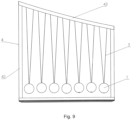
- the frame 4 comprises:
- height change of the beam 43 is represented by a change of the length of the strings 3 connected with the first magnetic bodies 1 which are maintained at the same height. This change will influence the factors such as the swing amplitude of the wave pendulum, the linear velocity of swing, and swing period, etc.
- versatile motion states of the first magnetic bodies may be exhibited via height changes of the beam 43, which improves the versatility of pendulum motion, thereby preventing the user from suffering from a fatigue visual experience, further improving the appeal for viewing .
- the height of the beam 43 may linearly ascend from one side to the other side, or gradually ascend non-linearly.
- the beam 43 may be further configured into a shape at least part of which is actuate, even a shape of wave as a whole, thereby improving the richness of variations.
- a shape of the frame 4 may have a plurality of variations.
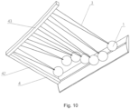
- the support pillar 42 may be provided in two, the two support pillars 42 being correspondingly arranged at two sides of the pendulum assembly; while as shown in Fig. 10 , the support pillar 42 may also be provided in one and arranged at a single side.
- the support pillar 42 may further be more variations.
- two or more rows of pendulum units are arranged in the pendulum assembly, and preset styles such as patterns and texts may be presented by swinging of pendulum units, wherein the beam 43 and the support pillar 42 may be integrally formed or separately connected, which do not affect implementation of the technical object of the present disclosure.
- first, second, and third may be used in the embodiments of the present disclosure to describe some components, such components should not be limited only to these terms. These terms are only used for distinguishing various components.
- a first certain component may also be referred to as a second certain component; similarly, the second certain component may also be referred to the first certain component.
- phrases such as “substantially equal to,” “substantially perpendicular to,” and “substantially symmetrical to” mean that the two referred to features are very close to the described relationship in terms of a macro size or a relative positional relationship.
- the positional relationship between objects can hardly be exactly constrained when it comes to a minor scale or a microscopic angle. Even the size and positional relationships therebetween have a minor error, implementation of the technical effect of the present disclosure will not be materially affected.
- the information, signal and data may be represented by any technology or technique among various technologies and techniques.
- the data, instructions, commands, information, signals, bits, code elements, chips may be represented by voltage, current, electromagnetic wave, magnetic field or magnetic particles, optical field or optical particles, or any combination of the above.
Landscapes
- Physics & Mathematics (AREA)
- Engineering & Computer Science (AREA)
- Electromagnetism (AREA)
- Health & Medical Sciences (AREA)
- Power Engineering (AREA)
- General Physics & Mathematics (AREA)
- Anesthesiology (AREA)
- Veterinary Medicine (AREA)
- Heart & Thoracic Surgery (AREA)
- Hematology (AREA)
- Life Sciences & Earth Sciences (AREA)
- Animal Behavior & Ethology (AREA)
- General Health & Medical Sciences (AREA)
- Public Health (AREA)
- Biomedical Technology (AREA)
- Psychology (AREA)
- Acoustics & Sound (AREA)
- Pain & Pain Management (AREA)
- Multimedia (AREA)
- Algebra (AREA)
- Computational Mathematics (AREA)
- Mathematical Analysis (AREA)
- Mathematical Optimization (AREA)
- Mathematical Physics (AREA)
- Pure & Applied Mathematics (AREA)
- Business, Economics & Management (AREA)
- Educational Administration (AREA)
- Educational Technology (AREA)
- Theoretical Computer Science (AREA)
- Toys (AREA)
- Vibration Prevention Devices (AREA)
Description
- The present disclosure relates to a pendulum unit according to the preamble of
claim 1. - A simple pendulum is a device that may produce a back-and-forth swing, where one end of a massless rod or a non-stretchable flexible string is suspended from a fixed point in a gravity field, and the other end thereof is fixedly tied with a massive bob. A bob swing restricted only to a vertical plane constitutes a planar simple pendulum; while a bob swing not limited only to a vertical plane constitutes a spherical simple pendulum.
- Due to its characteristic of back-and-forth motion, the simple pendulum may easily cause one to enter a mild hypnotic state when his/her attention is concentrated on it, thereby functioning to relieve fatigue and alleviate pressure. Therefore, the simple pendulum and its relevant derivatives are widely used as landscaping decors and desktop decors.
- Currently, derivatives of the simple pendulum for purposes of desktop decoration mainly include Newton's cradle, which is also referred to as Newton's balls or Executive Ball Clicker. The Newton's Cradle is a desktop demonstration device proposed by the French physicist Edme Mariotte as early as in 1676. In the Newton's Cradle, a plurality of spheres with an identical mass are fixed by strings and arranged densely with each other. When a sphere at either side swings back and forth to strike other densely arranged spheres, the sphere at the opposite side will be bounced out under the action of momentum conservation.
- However, motions of existing simple pendulums for desktop decoration purposes, such Newton's cradles or other derivatives, need to be actuated manually, and their motion processes are also very dull, such that they have limited effects of fatigue relief and pressure mitigation.
- When used as landscaping decorations, simple pendulums in spacious scenarios such as squares, lawns, and lobbies are mostly actuated by mechanical transmission, such that their motion patterns are also very monotonic and unappealing. Besides, mechanical transmission systems are generally highly complex, costly, and easily damageable or malfunctional.
A pendulum unit according to the preamble ofclaim 1 is known fromUS 4,011,674 B1 orUS 5,483,764 B1 . - To solve all or at least part of the technical problems above, a pendulum unit is provided in an embodiment of the present disclosure, comprising the features of
claim 1. - In the present disclosure, swinging of each first magnetic body is controlled by means of energizing, which further implements automatic control of the wave pendulum assembly. Compared with the prior art of actuating the swing by manually pushing a sphere to swing, the present disclosure realizes long-time and uninterrupted motion of the first magnetic bodies without a need of repeated manual intervention, thereby enhancing the convenience. Compared with pushing the first magnetic bodies to motion by means of mechanical transmission, the present disclosure offers a simple structure, a convenient implementation, a low cost, a long service life and a good robustness.
- Moreover, by controlling the magnitude of current upon energizing, the wave pendulum assembly of the present disclosure enables automatic change of the amplitude, frequency, and direction of the motion of each first magnetic body, forming a more enticing swing pattern, causing the motion process of the wave pendulum assembly not dull, providing a better effect of fatigue relief and pressure alleviation, and enhancing its appeal.
- To better elucidate the technical solutions in the embodiments of the present disclosure or in the prior art, the drawings used for describing the embodiments or the prior art will be briefly introduced below. It is apparent that the drawings as described only relate to some embodiments of the present disclosure. To those skilled in the art, other drawings may be derived based on these drawings without exercise of inventive work; technical features, connection relationships, and even process steps not mentioned herein may also be derived based on these drawings.
-
Fig. 1 is a planar schematic diagram of a pendulum unit according to a first embodiment of the present disclosure; -
Fig. 2 is a planar schematic diagram of a pendulum unit according to a second embodiment of the present disclosure; -
Fig. 3 is a planar schematic diagram of a pendulum unit according to a third embodiment of the present disclosure; -
Fig. 4 is a stereoscopic schematic diagram of a pendulum unit according to a fourth embodiment of the present disclosure; -
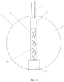
Fig. 5 is a sectional schematic view of a first magnetic body according to a fifth embodiment and an eighth embodiment of the present disclosure; -
Fig. 6 is a schematic diagram of a pendulum unit where a line realignment device is located according to a sixth embodiment and a ninth embodiment of the present disclosure: -
Fig. 7 is a top-view stereoscopic schematic diagram of a wave pendulum assembly according to a seventh embodiment of the present disclosure; -
Fig. 8 is a bottom-view stereoscopic schematic diagram of a wave pendulum assembly according to the seventh embodiment of the present disclosure; and -
Fig. 9 is a front-view schematic diagram of a wave pendulum assembly having dual support pillars according to a tenth embodiment of the present disclosure; and -
Fig. 10 is a stereoscopic schematic diagram of the wave pendulum assembly having a single support pillar according to the tenth embodiment of the present disclosure. -
- 1- first magnetic body; 11- housing; 12- channel; 13- electromagnetic device; 14-wire connector; 15- lead;
- 2- second magnetic body; 21- left electromagnet; 22- right electromagnet; 23- permanent magnet;
- 3- string:
- 4- frame; 41- pedestal; 42- support pillar; 43- beam; 44- battery compartment;45- cable; 5- conductive connector; 51- line realignment device; 511- electrically conductive reed; 512- bolt-nut assembly; 52- electrically conductive contact.
- To make the objects, technical solutions, and advantages of the embodiments of the present disclosure much clearer, the technical solutions in the embodiments of the present disclosure will be described clearly and comprehensively with reference to the accompanying drawings of the embodiments of the present disclosure; apparently, the embodiments as described are only part of the embodiments of the present disclosure, rather than all of them. All other embodiments obtained by those skilled in the art without exercise of inventive work based on the embodiments in the present disclosure shall fall within the protection scope of the present disclosure.
- The present disclosure discloses a pendulum unit and a wave pendulum assembly based on the pendulum unit.
- The Inventor of the present disclosure found that in the prior art, irrespective of a simple pendulum or a Newton's cradle, they all require an external force to exert an initial gravitational potential energy to swinging spheres such that the swinging spheres may motion under the momentum converted from the gravitational potential energy. During pendulum motion of the prior art, energy is constantly consumed by air friction as well as during transmission of swinging sphere, till being completely consumed; and the motion amplitude of swinging spheres will be gradually diminished; besides, the motion procedure of the swinging spheres is also very monotonic. After the energy is completely consumed, a further external force is needed to give the swinging spheres a new gravitational potential energy. Therefore, to maintain continued motion of the pendulum in the prior art, continuous manual intervention is needed, which is much inconvenient to manipulate and fails to provide a desired effect of fatigue relief and pressure mitigation. Without manual intervention, the prior art would need a complex mechanical transmission as dynamic source; consequently, besides a high manufacturing cost, this further poses a high demand on properties of the mechanical transmission structure such as rust-proof, anti-corrosion, dust-proof, sand-proof, and water-proof so as to cope with outdoor scenarios exposed to uncertain weathers. To handle severe display environments, the mechanical transmission structure needs to pay dearly; besides, it has serious drawbacks such as a high system complexity and a short service life.
- In view of the above, a pendulum unit is provided in a first embodiment of the present disclosure, as shown in
Fig. 1 , which comprises: - a
frame 4; - a first
magnetic body 1, the firstmagnetic body 1 being connected to theframe 4 via astring 3 and hung in the air; and - a second
magnetic body 2 fixedly disposed below the firstmagnetic body 1; wherein - at least one of the first
magnetic body 1 and the secondmagnetic body 2 may generate magnetism when being energized, such that the firstmagnetic body 1 may swing periodically in the air under a magnetic action of the first magnetic body and the second magnetic body. - In an embodiment, the
frame 4 may preferably comprise: - a
pedestal 41 on which the secondmagnetic body 2 is disposed; - a
beam 43 disposed above thepedestal 41, wherein the firstmagnetic body 1 is connected to thebeam 43 via thestring 3; and - a
support pillar 42 connected on thepedestal 41 to support thebeam 43. Thesupport pillar 42 may be configured separately at the left and right sides, as shown inFig. 1 , or configured to be one at a single side. To the allowed extent of bearing safety, thebeam 43 and thesupport pillar 42 may be integrally formed under a continuous curvature, so as to form an arcuate support structure. - It is particularly noted that the shape of the
support pillar 42 is not limited to a single straight-line profiled shape. In practice, it may be formed into a stereoscopic structure; when viewed from one side of the pendulum unit towards the firstmagnetic body 1, different viewing angles may present different viewing effects. Therefore, thesupport pillar 42 as adopted may be presented in various patterns such as an inverse "V" pattern, an arched door pattern, etc. Thesupport pillar 42 may also be made of a transparent or frosted material. - The
pedestal 41 may be formed with a housing into which the secondmagnetic body 2 is accommodated. Theframe 4 may form a support to the pendulum unit, such that the firstmagnetic body 1 may swing therein. - In this embodiment, illustration will be made with an example in which the second
magnetic body 2 may generate magnetism when being energized. In other words, the secondmagnetic body 2 itself may be an electromagnet, or the secondmagnetic body 2 is provided with an electromagnet inside. Besides, the firstmagnetic body 1 may be a common magnet or configured as a device that may generate magnetism when being energized. - To simplify configuration of the gravitational center of the first
magnetic body 1, the firstmagnetic body 1 may be formed as a spherical body or a regular polyhedron. When the spherical shape is adopted, an air friction subjected to the firstmagnetic body 1 may also be reduced. Of course, to provide more versatile user experience, the firstmagnetic body 1 may also assume some other irregular shapes, which does not constitute a limitation to the technical object of the present disclosure. - It is noted that the pendulum unit according to an embodiment of the present disclosure may control the circuit via an external control circuit, or may include a control circuit in itself, wherein the control circuit may comprise:
- a converter module that is electrically connected to the first
magnetic body 2; - and a control module that is in communicative connection with the converter module.
- In an embodiment, the control module may change the current in the first
magnetic body 1 and/or the secondmagnetic body 2 through a preset control logic. - Particularly, the way of changing the current includes, but is not limited to, changing the current magnitude and/or current direction so as to flexibly implement automatic control of the pendulum unit.
- Further, a memory module may be further provided. The memory module is in communication with the control module and may be used for storing control logic. By loading the control logic into the memory module, the user may autonomously edit or adapt the swing style of the first
magnetic body 1, so that the pendulum unit provides more fun to play, thereby improving user experience. - Moreover, the present disclosure may implement different patterns of periodic swing based on settings of the connection between the
string 3 and theframe 4. For example, when thestring 3 is a single string shown inFig. 1 and thestring 3 and theframe 4 are connected via a single connection point, the firstmagnetic body 1 may sway in a fashion of circle drawing above the secondmagnetic body 2. However, when thestring 3 is connected to theframe 4 via a revolving shaft, the firstmagnetic body 1 may swing laterally (front-rearward) as the revolving shaft revolves. - Further, illustration will be made with an example where the first
magnetic body 1 is a permanent magnet. Because the position of the firstmagnetic body 1 is fixed relative to the secondmagnetic body 2, a magnetic pole of the firstmagnetic body 1 facing the direction of the secondmagnetic body 2 is also relatively fixed. - When current in one direction is introduced in the second
magnetic body 2 to cause the magnetic poles of the secondmagnetic body 2 and the firstmagnetic body 1 to be opposite in a same direction, the firstmagnetic body 1 and the secondmagnetic body 2 repel each other. Because the secondmagnetic body 2 is fixedly disposed below the firstmagnetic body 1; the firstmagnetic body 1 starts swinging under a push of this repulsive force. By changing the direction and magnitude of the current in the secondmagnetic body 2 at appropriate time, the swinging action of the firstmagnetic body 1 may be controlled. For example, when the firstmagnetic body 1 is located at a position with a maximum amplitude, the firstmagnetic body 1 and the secondmagnetic body 2 are attracted to each other by changing the current direction; when the firstmagnetic body 1 is located at a lowest point, the firstmagnetic body 1 and the secondmagnetic body 2 repel each other by changing the current direction again; in this way, energy may be constantly replenished for the motion of the firstmagnetic body 1, and the amplitude of the firstmagnetic body 1 may be increased. For another example, the firstmagnetic body 1 and the secondmagnetic body 2 may be attracted to each other by directly changing the direction of current, and when this state is maintained, the firstmagnetic body 1 may quickly stop swinging. - When the first
magnetic body 1 may generate magnetism in the same way, current in the firstmagnetic body 1 and the secondmagnetic body 2 may be adjusted simultaneously to further increase the motion complexity of the firstmagnetic body 1. - It is noted that the pendulum unit may further comprise a power supply module, the power supply module supplying power to power-consuming components of the pendulum unit through any one of solar energy, wind energy, grid power or a combination thereof.
- For example, a battery module may be arranged inside the pendulum unit and a solar panel may be arranged on the top thereof, such that in fine days, the power generated by the solar energy actuates the first
magnetic body 1 to motion and meanwhile charges the battery module, while in rainy days, the battery module discharges to actuate the firstmagnetic body 1 to motion. When connected to the grid power, the extra generating capacity of the solar panel may also be integrated into the grid power to enhance energy utilization. Of course, implementation of the technical objective of the present disclosure will not be affected if the power is only supplied by solar energy, without arranging the battery module. - In the present disclosure, swing of the first
magnetic body 1 is controlled by energizing, which further implements automatic control of the pendulum unit. - Compared with the prior art where the swing is actuated by manually pushing the swinging spheres, the present disclosure needs no repeated manual intervention to realize long-time and uninterrupted motion of the first magnetic bodies, thereby enhancing the convenience. Further, compared with pushing the motion of the first
magnetic body 1 through mechanical transmission, the present disclosure only needs to arrange a pair of mutually cooperating magnetic bodies, so that multiple variations of motion speeds and motion patterns may be realized by simple electrical control, which reduces the structural complexity to a great extent, and provides a more convenient implementation, a lower cost, a longer service life, and higher robustness. - Moreover, by controlling the magnitude of current upon energizing, the pendulum unit of the present disclosure may autonomously change the amplitude, frequency, and direction of the motion of the first
magnetic body 1, thereby forming versatile interesting swinging patterns, so that the motion procedure of the pendulum unit is not dull, a better effect of fatigue relief and pressure alleviation is generated, and its appeal is enhanced. - A second embodiment of the present disclosure provides a pendulum unit; the pendulum unit according to the second embodiment is a further improvement of that in the first embodiment. The main improvement lies in that the second
magnetic body 2 comprises two electromagnets, i.e., aleft electromagnet 21 and aright electromagnet 22, respectively, as shown inFig. 2 . - Particularly, the two electromagnets are disposed at two sides below the first
magnetic body 1, respectively. They both may be energized through separate control circuits or through branch circuits of a general control circuit. - When the second
magnetic body 2 is configured as two separate electromagnets, the swinging manner of the firstmagnetic body 1 may be controlled by tuning the currents of different electromagnets. For example, when theleft electromagnet 21 and the firstmagnetic body 1 repel each other while theright electromagnet 22 and the firstmagnetic body 1 are attracted with each other, the firstmagnetic body 1 at the lowest point will quickly swing to the right; vice versa. Besides, when theleft electromagnet 21 and theright electromagnet 22 are both attracted mutually with the firstmagnetic body 1, the firstmagnetic body 1 may stop motioning. Furthermore, when theleft electromagnet 21 and theright electromagnet 22 are both repellant with the firstmagnetic body 1, the firstmagnetic body 1 may bounce. - Additionally, when the second
magnetic body 2 is configured as two separate electromagnets, the firstmagnetic body 1 may be caused only to sway laterally without adjusting the setting of thestring 3 when thestring 3 and theframe 4 are connected via a single connection point, thereby simplifying the connection structure of thestring 3. - In an embodiment of the present disclosure, a source for generating an initial force of pushing the first
magnetic body 1 to motion may be the magnetism generated by the secondmagnetic body 2 when being energized, or the magnetism generated by the firstmagnetic body 1 when being energized. - In the case that the first
magnetic body 1 may generate magnetism, a power source of the firstmagnetic body 1 may be a battery disposed inside the firstmagnetic body 1. However, if a battery is provided inside the firstmagnetic body 1, the internal structure of the firstmagnetic body 1 will become more complex. - In view of the above, a third embodiment of the present disclosure provides a pendulum unit; the pendulum unit according to the third embodiment is a further improvement of the pendulum unit according to the first or second embodiment. The main improvement lies in that in the third embodiment of the present disclosure, the
string 3 may conduct electricity, such that the firstmagnetic body 1 may generate magnetism when being energized. - Particularly, the
string 3 may conduct electricity via at least one electrically conductive cable inside thestring 3 or is directly made of an electrically conductive material. For example, thestring 3 may be directly made of steel, copper or some metal alloy materials. - By conducting the
string 3 to an external battery, a weight of the firstmagnetic body 1 may be reduced, the internal structure of the firstmagnetic body 1 may be simplified, and the cost may be lowered. - Preferably, as shown in
Fig. 3 , the pendulum unit may further comprise: - a
battery compartment 44 that is disposed inside thepedestal 41, for accommodating a battery module; and - a
cable 45 that is electrically connected to a battery module and astring 3, thecable 45 being at least partially disposed inside asupport pillar 42. - Particularly, the battery may be a lithium battery, a dry battery, or some other common batteries; further, a
battery compartment 44 may be provided inside theframe 4, particularly inside thepedestal 41 of theframe 4, and the battery is disposed inside thebattery compartment 44. By disposing the battery in thepedestal 41, it is beneficial for reasonable counterweight arrangement of the pendulum unit to prevent toppling of the pendulum unit.. Of course, the battery might not be arranged; instead, the power is supplied via AC input. - It is particularly noted that when magnetism is needed, it is always envisaged to energize the second
magnetic body 2 to generate magnetism while setting the firstmagnetic body 1 as permanent magnet. In this way, the structure of the firstmagnetic body 1 may be simplified. When the firstmagnetic body 1 is always in a motion state, a simpler structure causes the pendulum unit easier to be manufactured. - However, this arrangement is more suitable for a small-sized pendulum unit. When the pendulum unit is applied to a large decor, in order to enable the first
magnetic body 1 to implement a simple pendulum motion, the options may include: providing a secondmagnetic body 2 including two electromagnets, or changing the connecting structure between the firstmagnetic body 1 and theframe 4, e.g., setting the connecting structure as a revolving shaft. Arrangement of the two electromagnets will cause the cost to rise, while setting the connecting structure as a revolving shaft poses a high demand on the bearing of the revolving shaft structure, which also increases the cost. - However, an embodiment of the present disclosure innovatively causes the first
magnetic body 1 to be able to generate magnetism when being energized, so that with the firstmagnetic body 1 as an electromagnet capable of generating magnetism when being energized and with astring 3 to conduct the current, it is unnecessary to arrange a battery on the firstmagnetic body 1; in this way, the structure of the firstmagnetic body 1 is not complex. Further, as it is only needed to provide on electromagnet on the firstmagnetic body 1 and the firstmagnetic body 1 and theframe 4 may be connected in any manner, the structure is significantly simplified, the cost is lowered, and the service life is prolonged. - A fourth embodiment of the present disclosure provides a pendulum unit, which is a further improvement of that in the third embodiment. The main improvement lies in providing a more appropriate arrangement of permanent magnets.
- Specifically, as shown in
Fig. 4 , the secondmagnetic body 2 comprises twopermanent magnets 23 oppositely disposed, when in a static state, at two sides below the firstmagnetic body 1, wherein magnetic poles of the twopermanent magnets 23 facing the firstmagnetic body 1 side are N pole and S pole, respectively. - It may be understood that by setting the magnetic poles of the same sides of the two
permanent magnets 23 to be opposite to each other, irrespective of which direction of current is introduced into the firstmagnetic body 1, the firstmagnetic body 1 will surely obtain an acceleration towards the direction of onepermanent magnet 23 thereof, which may simplify the control logic of the circuit. - Further, at least two
strings 3 may be correspondingly connected to the firstmagnetic body 1, wherein a line B that connects connection points between the twostrings 3 and theframe 4 is perpendicular to a line C that connects midpoints of the twopermanent magnets 23. - Apparently, as shown in
Fig. 4 , when the line B that connects connection points between the twostrings 3 and theframe 4 is perpendicular to the line C that connects midpoints of the twopermanent magnets 23, a swinging direction of the firstmagnetic body 1 may be further restricted. In other words, the firstmagnetic body 1 swings back and forth constantly along a direction approximate to the connecting line C under the joint restriction of thestring 3 and the twopermanent magnets 23. - Compared with a structure of providing a revolving shaft or a pulley on one
string 3, providing of twostrings 3 not only enables sharing of the stresses on the connection points of thestrings 3, but also lowers the requirement on the structural complexity of the connection points so as to reduce the cost. - Additionally, when the
string 3 may conduct electricity, twostrings 3 may provide a conductive connection between anode and cathode, respectively. Compared with connecting the positive and negative wires both to the inside of thesame string 3, providing of the twostrings 3 significantly alleviates the burden on the structure of thestrings 3 and prolongs the service life of thestrings 3. It is noted that the positive and negative wires of the power supply may also be arranged in asame string 3, which does not affect implementation of the technical objective of the present disclosure - Additionally, the
permanent magnets 23 preferably have a substantially elongated shape, and a length direction of thepermanent magnets 23 is parallel to a direction of the line that connects the connection points between the twostrings 3 and theframe 4. Similarly, the connection line direction of thepermanent magnets 23 may be made substantially vertical to the direction of the line that connects the connection points between the twostrings 3 and theframe 4, thereby restricting the motion trajectory of the firstmagnetic body 1 in the length direction of thepermanent magnets 23. By virtue of the elongated magnet, the firstmagnetic body 1 may be better restricted within the magnetic field range of thepermanent magnet 23, the motion trajectory of the firstmagnetic body 1 may be stabilized, and fatigue of thestring 3 may be prevented due to constant change of stress directions and thus being pulled in a plurality of directions, thereby prolonging the service life. - A fifth embodiment of the present disclosure provides a pendulum unit; the pendulum unit according to the fifth embodiment is a further improvement of the pendulum unit according to any of the first through fourth embodiments. In the fifth embodiment of the present disclosure, a preferred internal structure of the first
magnetic body 1 is revealed. - Specifically, as shown in
Fig. 5 , the firstmagnetic body 1 comprises: - a
housing 11 in which achannel 12 is formed; - an
electromagnetic device 13 accommodated in one side of thechannel 12; and - a
wire connector 14 accommodated in the other side of thechannel 12, alead 15 of theelectromagnetic device 13 being conductively connected to thewire connector 14 and electrically connected to thestring 3 via thewire connector 14. - Preferably, the
housing 11 is formed spherically, and thechannel 12 passes through a center of thehousing 11. Thechannel 12 passing through the center of thehousing 11 has little impact on the gravitational center of thehousing 11, such that it may mitigate the influence of the swinging firstmagnetic body 1. - Particularly, by arranging the
electromagnetic device 13 and thewire connector 14 at two sides below the firstmagnetic body 1 using thechannel 12, respectively, theelectromagnetic device 13 may be as close as possible to the secondmagnetic body 2 to produce a larger magnetic action. - Preferably, a hole is formed on the
housing 11, via which hole thestring 3 is connected to thewire connector 14; - A portion of the
housing 11 where the hole is formed may be used to block thewire connector 14 from leaving thechannel 12. Thewire connector 14 as provided plays a weight-bearing role under a pulling action of thestring 3 , which may prevent the lead 15 from being directly stressed, thereby prolonging the service life. - Preferably, a diameter of a portion of the
channel 12 accommodating theelectromagnetic device 13 is greater than a diameter of the remaining portions. If the diameter of the side where theelectromagnetic device 13 is located is larger, thewire connector 14 and theelectromagnetic device 13 may be mounted from that side, such that the portion of thehousing 11 where the hole is formed still maintains integral with the remaining portions of thehousing 11, which improves the structural strength of thehousing 11. - The first
magnetic body 1 may be mounted in the following steps: - 1. penetrating the
string 3 into thechannel 12 via the hole and out of the other end of thechannel 12; - 2. connecting the
out string 3 to thewire connector 14, and conductively welding thelead 15 to thestring 3; - 3. placing the
wire connector 14 and theelectromagnetic device 13 successively into thechannel 12, such that thewire connector 14 is pulled to a terminal of thechannel 12 via thestring 3; wherein - 4. at this point, the
lead 15 is relaxed inside thechannel 12; an end of thechannel 12 where theelectromagnetic device 13 is located may be blocked by a cover, thereby completing mounting of the firstmagnetic body 1. - The structure of the first
magnetic body 1 in this embodiment sufficiently considers the arrangement of respective lines and the layout of thelead 15, which improves the tensile strength of the internal lines of the firstmagnetic body 1 and prolongs the service life of the firstmagnetic body 1. - A sixth embodiment of the present disclosure provides a pendulum unit; the pendulum unit according to the sixth embodiment is a further improvement of the pendulum unit according to any of the first through fifth embodiments. In the sixth embodiment of the present disclosure, a preferred length adjustable structure of the
string 3 is revealed. - Referring to
Fig. 6 , in this embodiment, aconductive connector 5 is provided inside the frame; a line realignment device 51 is provided on theconductive connector 5, and thestring 3 is connected to the line realignment device 51 and is electrically connected to theconductive connector 5 via the line realignment device 51. - Motion of a single first
magnetic body 1 of the pendulum unit according to the present disclosure may be approximated as a simple pendulum motion. Based on a period formula of the simple pendulum:
T=2π√(L/g) where T denotes the period, L denotes the length of the pendulum, and g denotes the local gravitational acceleration. - It is seen that by adjusting the length of the
string 3 with the line realignment device 51, a motion period (i.e., motion frequency) of the firstmagnetic body 1 may be adjusted. Moreover, the swing amplitude may be controlled by adjusting the length of thestring 3. Therefore, when the line realignment device is provided, the motion change patterns of the firstmagnetic body 1 may be enriched with the line realignment device 51. - Furthermore, a through hole and an electrically
conductive contact 52 are provided on theconductive connector 5. - The line realignment device 51 comprises:
- an electrically
conductive reed 511 and a bolt-nut assembly 512, one end of the electricallyconductive reed 511 being relatively fixed by the bolt-nut assembly 512 that penetrates through the through hole, the other end thereof abutting against the electricallyconductive contact 52; wherein - the
string 3 is in electrical connection with the electricallyconductive reed 511 via the nut-bolt assembly 512. - Specifically, the nut-bolt assembly 512 may include a combination of bolt, nut, and gasket, etc.; when the bolt penetrates through the
conductive connector 5 and the electricallyconductive reed 511, thestring 3 wound around the bolt is in electrical connection with the electricallyconductive reed 511 via a gasket through the connection between the nut and the bolt. The electricallyconductive reed 511 is fixed to the circuit and meanwhile in interference-contact with the electricallyconductive contact 52, such that thestring 3 implements conduction with theconductive connector 5, further causing thestring 3 to be conductive with the remaining portions of the pendulum unit. - Additionally, a receiving box may be provided such that the excessive portion of the
string 3 is received inside the receiving box, to prevent thestring 3 from aging or accidental contact. - The present disclosure further provides a method of adjusting the length of the
string 3 adapted to the structure: - 1. penetrating the bolt through the hole on the
conductive connector 5, the bolt being relatively fixed using a first nut; - 2. sleeving a first gasket on the bolt, winding the
string 3 around the bolt, and adjusting thestring 3 to a desired length; - 3. sleeving the electrically
conductive reed 511 on the bolt, causing the electricallyconductive reed 511 to contact with the electricallyconductive contact 52; - 4. sleeving a second gasket on the bolt, and tightly fixing respective gaskets,
string 3, and the electricallyconductive reed 511 using a second nut, causing the electricallyconductive reed 511 to interference-contact with the electricallyconductive contact 52. - The length-adjustable structure of the
string 3 provided in this embodiment may extend or withdraw a projected length of thestring 3 as required and meanwhile maintain the electrically connection state of thestring 3, providing a simple structure and a convenient manipulation. The user may adjust the swinging effect of the firstmagnetic body 1 by adjusting the projected length of thestring 3 based on timing and needs, such that the pendulum unit in this embodiment provides a higher versatility. - A seventh embodiment of the present disclosure provides a wave pendulum assembly. The wave pendulum assembly according to the seventh embodiment comprises the pendulum unit according to any of the first through sixth embodiments.
- Specifically, as shown in
Fig. 7 , the wave pendulum assembly comprises: - a
frame 4 and a plurality of firstmagnetic bodies 1, respective firstmagnetic bodies 1 being connected to theframe 4 viastrings 3 and hung in the air; and - second
magnetic bodies 2, the amount of which is identical to that of the first magnetic bodies, the second magnetic bodies being fixedly disposed below the firstmagnetic bodies 1 in a one-to-one correspondence; wherein - in the first
magnetic bodies 1 and the secondmagnetic bodies 2, at least one party may generate magnetism when being energized, such that the firstmagnetic bodies 1 may swing periodically in the air under a magnetic action between the firstmagnetic bodies 1 and the secondmagnetic bodies 2. - In an embodiment, the
frame 4 may preferably comprise: - a
pedestal 41 on which the secondmagnetic bodies 2 are disposed; - a
beam 43 disposed above thepedestal 41, wherein the firstmagnetic bodies 1 are connected to thebeam 43 via thestrings 3; and - a
support pillar 42 that is connected to thepedestal 41 to support thebeam 43. - The
pedestal 41 may be formed with a housing into which the secondmagnetic bodies 2 are accommodated. Theframe 4 as provided may form a support to the wave pendulum assembly, for the firstmagnetic bodies 1 to swing. - To simplify configuration of the gravitational center of a first
magnetic body 1, the firstmagnetic body 1 may be formed as a spherical body or a regular polyhedron. When the spherical shape is adopted, an air friction subjected to the firstmagnetic body 1 may also be reduced. Of course, to provide more versatile user experience, the firstmagnetic body 1 may also assume some other irregular shapes, which does not constitute a limitation to the technical object of the present disclosure. - In an embodiment of the present disclosure, a source for generating an initial force of pushing the first
magnetic body 1 to motion may be the magnetism generated by the secondmagnetic body 2 when being energized, or the magnetism generated by the firstmagnetic body 1 when being energized. - Preferably, in this embodiment, the
string 3 may conduct electricity, such that the firstmagnetic body 1 may generate magnetism when being energized. - Particularly, the
string 3 may conduct electricity via an electrically conductive cable inside thestring 3 or may be directly made of an electrically conductive material. For example, thestring 3 may be directly made of steel, copper or some metal alloy materials. - By conductively connecting the
string 3 to an external battery, a weight of the firstmagnetic body 1 may be reduced, the internal structure of the firstmagnetic body 1 may be simplified, and the cost may be lowered. - It is particularly noted that generally, when it is needed to generate magnetism, it is always conceived to cause the second
magnetic bodies 2 to generate magnetism when being energized, the firstmagnetic bodies 1 are configured as permanent magnets. This may simplify the structure of the firstmagnetic body 1. When the firstmagnetic body 1 is constantly in a motion state, a simpler structure may cause the pendulum unit to be manufactured more easily. - However, this arrangement is more suitable for a circumstance that the pendulum unit is a small-sized pendulum. To adapt the pendulum unit to a large-sized pendulum, a second
magnetic body 2 including two electromagnets needs to be provided, or a structure of the joint between the firstmagnetic body 1 and theframe 4 needs to be changed, e.g., configuring the joint structure as a revolving shaft, so as to enable the firstmagnetic body 1 to implement a pendulum motion. Particularly, in the pendulum assembly, when a plurality of pendulum units are provided, configuring of two electromagnets will cause the cost to rise dramatically; besides, when a plurality of electromagnets are provided in a same plane, mutual interference between the electromagnets and circuit control problems may arise; while the joint structure is arranged as a revolving shaft, it is relatively demanding on the bearing capacity of the revolving shaft structure, which will undoubtedly increase the cost. - However, an embodiment of the present disclosure innovatively causes the first
magnetic bodies 1 to generate magnetism when being energized, where the firstmagnetic bodies 1 are used as electromagnets that may generate magnetism when being energized, and current is conducted via thestring 3. Because it is not needed to arrange a battery on the firstmagnetic bodies 1, the structure of the firstmagnetic bodies 1 is simplified. Further, as it is only needed to arrange an electromagnet on the firstmagnetic bodies 1 and the firstmagnetic bodies 1 and the frame may be connected arbitrarily, the structure is significantly simplified, the cost is lowered, and the service life is prolonged. - Particularly, the pendulum assembly may further comprise a power supply module, the power supply module supplying power to power-consuming components of the pendulum assembly through any one of solar energy, wind energy, grid power or a combination thereof.
- For example, a battery module may be arranged inside the pendulum assembly and a solar panel may be arranged on the top thereof, such that in fine days, the power generated by the solar energy actuates the first
magnetic body 1 to motion and meanwhile charges the battery module, while in rainy days, the battery module discharges to actuate the firstmagnetic body 1 to motion. When connected to the grid power, the extra generating capacity of the solar panel may also be integrated into the grid power to enhance energy utilization - Preferably, as shown in
Fig. 8 , the wave pendulum assembly may further comprise: - a
battery compartment 44 disposed in thepedestal 41, for accommodating a battery module; and - a
cable 45 electrically connected to the battery module and astring 3, thecable 45 being at least partially disposed inside asupport pillar 42. - Particularly, the battery may be a lithium battery, a dry battery, or some other common batteries; further, a
battery compartment 44 may be provided inside theframe 4, particularly inside thepedestal 41 of theframe 4, wherein the battery is disposed inside thebattery compartment 44. By disposing the battery in thepedestal 41, it is beneficial for reasonable counterweight arrangement of the wave pendulum assembly to prevent the wave pendulum assembly from toppling. - In this embodiment, a more appropriate layout of the permanent magnets is further provided.
- Specifically, as shown in
Fig. 7 , the secondmagnetic body 2 comprises twopermanent magnets 23 oppositely disposed, in a stationary state, at two sides below the firstmagnetic body 1, and the magnetic poles of the twopermanent magnets 23 facing the firstmagnetic body 1 side are N pole and S pole, respectively. - It may be understood that by setting the magnetic poles of the two
permanent magnets 23 at the same side to be opposite to each other, irrespective of which direction of current is introduced into the firstmagnetic body 1, the firstmagnetic body 1 will surely obtain an acceleration towards the direction of onepermanent magnet 23 thereof, such that the control logic of the circuit may be simplified. - Further, at least two
strings 3 may be correspondingly connected to the firstmagnetic body 1, wherein a line B that connects connection points between the twostrings 3 and theframe 4 is perpendicular to a line C that connects midpoints of the twopermanent magnets 23. - Apparently, as shown in
Fig. 7 , when the line B that connects connection points between the twostrings 3 and theframe 4 is perpendicular to the line C that connects midpoints of the twopermanent magnets 23, a swinging direction of the firstmagnetic body 1 may be further restricted. In other words, the firstmagnetic body 1 will swing back and forth constantly along a direction approximate to the connecting line C under the joint restriction of thestring 3 and the twopermanent magnets 23. - Compared with a structure of providing a revolving shaft or a pulley on one
string 3, providing of twostrings 3 not only enables sharing of the stresses on the connection points of thestrings 3, but also lowers the requirement on the structural complexity of the connection points so as to reduce the cost. - Additionally, when the
string 3 may conduct electricity, twostrings 3 may provide a conductive connection between anode and cathode, respectively. Compared with connecting the positive and negative wire both to the inside of thestring 3, providing of twostrings 3 significantly alleviates the burden to the structure of thestring 3 and extends the service life of thestring 3. - Additionally, the
permanent magnets 23 preferably have a substantially elongated shape, and a length direction of thepermanent magnets 23 is parallel to a direction of the line that connects connection points between the twostrings 3 and theframe 4. Similarly, the connection line direction of thepermanent magnets 23 may be made substantially vertical to the direction of the line that connects the connection points between the twostrings 3 and theframe 4, thereby restricting the motion trajectory of the firstmagnetic bodies 1 in the length direction of thepermanent magnets 23. By virtue of the elongated magnets, the firstmagnetic bodies 1 may be better restricted within the magnetic field range of thepermanent magnets 23, the motion trajectory of the firstmagnetic bodies 1 may be stabilized, and fatigue of thestrings 3 may be prevented due to constant change of stress directions and thus being pulled in a plurality of directions, thereby prolonging the service life. - It is noted that the wave pendulum assembly according to an embodiment of the present disclosure may control the circuit via an external control circuit, or may comprise a control circuit in itself, wherein the control circuit may comprise:
- a converter module that is electrically connected to a second
magnetic body 2; - and a control module that is in communicative connection with the converter module.
- Particularly, the control module may change the current in the first
magnetic body 1 and/or the secondmagnetic body 2 through a preset control logic. - Specifically, the manner of changing the current includes, but is not limited to, changing the current magnitude and/or current direction, such that automatic control of the pendulum assembly may be flexibly implemented.
- Further, a storage module may be provided. The storage module is in communication with the control module and may be used for storing the control logic. By loading the control logic into the storage module, the user may autonomously edit or adapt the swing style of the first
magnetic body 1, such that the pendulum assembly may provide more fun to play, thereby improving user experience. Specifically, a plurality of "swinging modes" may be pre-stored in the memory module, and the user may select and play these "swinging modes" based on his/her preferences, thereby achieving a desired motion effect. - This embodiment may change the arrangement style created by respective first
magnetic bodies 1 by controlling different swinging time sequences of the firstmagnetic bodies 1. For example, the initial timing for swinging of the firstmagnetic bodies 1 may be delayed at a preset interval in sequence, such that respective firstmagnetic bodies 1 form a wave-like swinging style shown inFig. 7 ; for another example, by introducing currents of different directions into the firstmagnetic bodies 1 at odd-number positions and the first magnetic bodies at even-number positions, the respective neighboring firstmagnetic bodies 1 may swing in different directions. The control module may switch between different control logics, such that the swinging manners of the firstmagnetic bodies 1 become richer and more versatile, further improving the fun of viewing the wave pendulum assembly. - Additionally, the wave pendulum assembly may further comprise a music module in communicative connection with the control module. The music module may play music, and may further play the music stored in a memory module; while the control module may adjust the swinging state of each first
magnetic body 1 through the played music, such that swinging of the firstmagnetic body 1 may be in tune with the music, thereby promoting the pleasure of watching. - In the present disclosure, swing of respective first
magnetic bodies 1 is controlled by energizing, which further implements automatic control of the pendulum module. - Compared with the prior art where the swing is actuated by manually pushing the swinging spheres, the present disclosure needs no repeated manual intervention to realize long-time and uninterrupted motion of the first magnetic bodies, thereby enhancing the convenience. Moreover, compared with pushing the motion of the first
magnetic body 1 through mechanical transmission, the present disclosure only needs to arrange a pair of mutually cooperating magnetic bodies, so that multiple variations of motion speeds and motion patterns may be realized by simple electrical control, which reduces the structural complexity to a great extent, and provides a more convenient implementation, a lower cost, a longer service life, and higher robustness. - Moreover, by controlling the magnitude of current upon energizing, the pendulum assembly of the present disclosure may autonomously change the amplitude, frequency, and direction of the motion of each first
magnetic body 1, thereby forming more interesting swinging patterns, so that the motion procedure of the pendulum assembly is not dull, a better effect of fatigue relief and pressure alleviation is implemented, and its appeal is enhanced. - .
- An eighth embodiment of the present disclosure provides a wave pendulum assembly; the wave pendulum assembly according to the eighth embodiment is a further improvement of the wave pendulum assembly according to the seventh embodiment. In the eighth embodiment of the present disclosure, a preferred internal structure of the first
magnetic body 1 is revealed. - Specifically, as shown in
Fig. 8 , the firstmagnetic body 1 comprises: - a
housing 11 in which achannel 12 is formed; - an
electromagnetic device 13 accommodated in one side of thechannel 12; and - a
wire connector 14 accommodated in the other side of thechannel 12, alead 15 of theelectromagnetic device 13 being conductively connected to thewire connector 14 and electrically connected to thestring 3 via thewire connector 14. - Preferably, the
housing 11 is formed spherically, and thechannel 12 passes through a center of thehousing 11. Thechannel 12 passing through the center of thehousing 11 may balance the gravitational center of thehousing 11, thereby mitigating the influence of the swinging firstmagnetic body 1. - Particularly, by arranging the
electromagnetic device 13 and thewire connector 14 at two sides below the firstmagnetic body 1 using thechannel 12, respectively, theelectromagnetic device 13 may be as close as possible to the second magnetic body 2 a to produce a larger magnetic force. - Preferably, a hole is formed on the
housing 11, via which hole thestring 3 is connected to thewire connector 14; - A portion of the
housing 11 where the hole is formed may be used to prevent thewire connector 14 from leaving thechannel 12. Thewire connector 14 as provided plays a role of bearing thestring 3, which may prevent the lead 15 from being directly stressed, thereby prolonging the service life. - Preferably, a diameter of a portion of the
channel 12 accommodating theelectromagnetic device 13 is greater than a diameter of the remaining portions. If the diameter of the side where theelectromagnetic device 13 is located is larger, thewire connector 14 and theelectromagnetic device 13 may be mounted from that side, such that the portion of thehousing 11 where the hole is formed still maintains integral with the remaining portions of thehousing 11, which improves the structural strength of thehousing 11. - The first
magnetic body 1 may be mounted in the following steps: - 1. penetrating the
string 3 into thechannel 12 via the hole and out of the other end of thechannel 12; - 2. connecting the
out string 3 to thewire connector 14, and conductively welding thelead 15 to thestring 3; - 3. placing the
wire connector 14 and theelectromagnetic device 13 successively into thechannel 12, such that thewire connector 14 is pulled to a terminal of thechannel 12 via thestring 3; wherein - 4. at this point, the
lead 15 is relaxed inside thechannel 12; an end of thechannel 12 where theelectromagnetic device 13 is located may be blocked by a cover, thereby completing mounting of the firstmagnetic body 1. - The structure of the first
magnetic body 1 in this embodiment sufficiently considers the arrangement of respective lines and the layout of thelead 15, which improves the tensile strength of the internal lines of the firstmagnetic body 1 and prolongs the service life of the firstmagnetic body 1. - A ninth embodiment of the present disclosure provides a wave pendulum assembly; the wave pendulum assembly according to the ninth embodiment is a further improvement of the wave pendulum assembly according to the seventh or eighth embodiment. In the ninth embodiment of the present disclosure, a preferred length-adjustable structure of a
string 3 is revealed. - Referring to
Fig. 6 , in this embodiment, aconductive connector 5 is provided inside the frame; a line realignment device 51 is provided on theconductor connector 5, and thestring 3 is connected to the line realignment device 51 and is electrically connected to theconductor connector 5 via the line realignment device 51. - Motion of a single first
magnetic body 1 of the pendulum assembly according to the present disclosure may be approximated as a simple pendulum motion. Based on a period formula of simple pendulum:
T=2π√(L/g) where T denotes the period, L denotes the length of the pendulum, and g denotes the local gravitational acceleration, - it is seen that by adjusting the length of the
string 3 with the line realignment device 51, a motion period (i.e., motion frequency) of the firstmagnetic body 1 may be adjusted. Moreover, the swing amplitude may be controlled by adjusting the length of thestring 3. Therefore, when the line realignment device is provided, the motion change patterns of the firstmagnetic body 1 may be enriched through the line realignment device 51. - Furthermore, a through hole and an electrically
conductive contact 52 are provided on theconductive connector 5. - The line realignment device 51 comprises:
- an electrically
conductive reed 511 and a bolt-nut assembly 512, one end of the electricallyconductive reed 511 being relatively fixed by the bolt-nut assembly 512 that penetrates through the through hole, the other end thereof abutting against the electricallyconductive contact 52; wherein - the
string 3 is in electrical contact with the electricallyconductive reed 511 via the nut-bolt assembly 512. - Specifically, the nut-bolt assembly 512 may include a combination of bolt, nut, and gasket, etc.; when the bolt penetrates through the
conductive connector 5 and the electricallyconductive reed 511, thestring 3 wound around the bolt is in electrical contact and conduction with the electricallyconductive reed 511 via a gasket through the connection between the nut and the bolt. While the electricallyconductive reed 511 is fixed to the circuit, it is in interference-contact with the electricallyconductive contact 52, such that thestring 3 implements conduction with theconductive connector 5, further causing thestring 3 to be conductive with the remaining portions of the pendulum assembly. - Additionally, a receiving box may be provided such that the excessive portion of the
string 3 is received inside the receiving box, to prevent thestring 3 from aging or accidental contact. - The present disclosure further provides a method of adjusting the length of the
string 3 adapted to the structure: - 1. penetrating the bolt through the hole on the
conductive connector 5, the bolt being relatively fixed using a first nut; - 2. sleeving a first gasket on the bolt, winding the
string 3 around the bolt, and adjusting thestring 3 to a desired length; - 3. sleeving the electrically
conductive reed 511 on the bolt, causing the electricallyconductive reed 511 to contact with the electricallyconductive contact 52; - 4. sleeving a second gasket on the bolt, and tightly fixing respective gaskets,
string 3, and the electricallyconductive reed 511 using a second nut, causing the electricallyconductive reed 511 to interference-contact with the electricallyconductive contact 52. - The length-adjustable structure of the
string 3 provided in this embodiment may extend or withdraw a projected length of thestring 3 as required and meanwhile maintain the electrically connection state of thestring 3, providing a simple structure and a convenient manipulation. The user may adjust the swinging effect of the firstmagnetic body 1 by adjusting the projected length of thestring 3 based on timing and needs, such that the wave pendulum assembly in this embodiment provides a higher versatility. - A tenth embodiment of the present disclosure provides a wave pendulum assembly; the wave pendulum assembly according to the tenth embodiment is a further improvement of the wave pendulum assembly according to any of the seventh through tenth embodiments. In the tenth embodiment of the present disclosure, as shown in
Fig. 9 , theframe 4 comprises: - a
beam 43, wherein the firstmagnetic body 1 is connected to thebeam 43 via thestring 3; and - a height of the
beam 43 gradually ascends from one side to the other side, and heights of the plurality of firstmagnetic bodies 1 are substantially consistent. - When the
beam 43 is not ahorizontal beam 43, height change of thebeam 43 is represented by a change of the length of thestrings 3 connected with the firstmagnetic bodies 1 which are maintained at the same height. This change will influence the factors such as the swing amplitude of the wave pendulum, the linear velocity of swing, and swing period, etc. In one wave pendulum assembly, versatile motion states of the first magnetic bodies may be exhibited via height changes of thebeam 43, which improves the versatility of pendulum motion, thereby preventing the user from suffering from a fatigue visual experience, further improving the appeal for viewing . - Particularly, the height of the
beam 43 may linearly ascend from one side to the other side, or gradually ascend non-linearly. When the height of thebeam 43 ascends non-linearly, i.e., when thebeam 43 has a certain curvature, more versatile changes are provided, thereby offering a higher appeal of viewing and a better effect of pressure relief. Additionally, thebeam 43 may be further configured into a shape at least part of which is actuate, even a shape of wave as a whole, thereby improving the richness of variations. - Further, in an embodiment of the present disclosure, a shape of the
frame 4 may have a plurality of variations. Typically, as shown inFig. 9 , thesupport pillar 42 may be provided in two, the twosupport pillars 42 being correspondingly arranged at two sides of the pendulum assembly; while as shown inFig. 10 , thesupport pillar 42 may also be provided in one and arranged at a single side. There may further be more variations. For example, two or more rows of pendulum units are arranged in the pendulum assembly, and preset styles such as patterns and texts may be presented by swinging of pendulum units, wherein thebeam 43 and thesupport pillar 42 may be integrally formed or separately connected, which do not affect implementation of the technical object of the present disclosure. - Those skilled in the art may adopt more specific transformed structures according to actual conditions. It should be understood that any transformations of the technical solutions of the present disclosure should fall within the protection scope of the present disclosure.
- It should be understood that the terms used in the embodiments of the present disclosure are only for the purpose of describing preferred embodiments, rather than limiting the present disclosure. The singular form "a," "an," or "the" used in the embodiments and appended claims of the present disclosure is also intended to include plurality; unless otherwise clearly specified in the context, "plurality" generally includes at least two, but does not exclude a circumstance of at least one.
- It should be understood that, the term "and/or" used herein only describes an association between correlated objects, which indicates that three kinds of relationships may exist. For example, A and/or B may indicate: only A exists, both A and B exist, and only B exists. Additionally, the symbol "/" in the context generally indicates an "or" relationship between the former object and the latter associated object.
- It should be understood that although terms such as first, second, and third may be used in the embodiments of the present disclosure to describe some components, such components should not be limited only to these terms. These terms are only used for distinguishing various components. For example, without departing from the scope of the embodiments of the present disclosure, a first certain component may also be referred to as a second certain component; similarly, the second certain component may also be referred to the first certain component.
- In the embodiments of the present disclosure, phrases such as "substantially equal to," "substantially perpendicular to," and "substantially symmetrical to" mean that the two referred to features are very close to the described relationship in terms of a macro size or a relative positional relationship. However, it is clear to those skilled in the art that due to objective factors such as errors and tolerances, the positional relationship between objects can hardly be exactly constrained when it comes to a minor scale or a microscopic angle. Even the size and positional relationships therebetween have a minor error, implementation of the technical effect of the present disclosure will not be materially affected.
- It needs also be noted that the terms "include," "comprise" or any other variables intend for a non-exclusive inclusion, such that a product or system including a series of elements not only includes those elements, but also includes other elements that are not explicitly specified or further includes the elements inherent in the product or system. Without more restrictions, an element limited by the phase "including one ..." does not exclude a presence of further equivalent elements in the product or system including the elements.
- In various embodiments above, although the method is illustrated and described as a series of actions to simplify the understanding, a person of normal skill in the art should understand and appreciate that the method is not limited by the sequence of actions, because according to one or more embodiments, some actions may occur in accordance with different sequences and/or correctly occur with other actions illustrated and described herein or those that, although not illustrated and described herein, may be understood by those skilled in the art.
- Those skilled in the art may understand, the information, signal and data may be represented by any technology or technique among various technologies and techniques. For example, the data, instructions, commands, information, signals, bits, code elements, chips may be represented by voltage, current, electromagnetic wave, magnetic field or magnetic particles, optical field or optical particles, or any combination of the above.
- Those skilled in the art will further appreciate that various explanatory logic sections, modules, units, circuits and algorithm steps described in conjunction with the embodiments disclosed herein may be implemented as electronic hardware, computer software, or a combination thereof. To clearly explain this interchangeability between hardware and software, various explanatory components, blocks, modules, units, circuits, and steps are generally described above in a functional way. Whether such functionalities are implemented as hardware or software is dependent on their specific applications and design constraints imposed on the overall system. For each particular application, those skilled in the art may implement the described functionality by different means, but such implementation decisions should not be interpreted as a cause of departing from the scope of the present disclosure.
- Finally, it should be noted that those of normal skill in the art may understand that many technical details provided in the various embodiments above are only for the readers to understand better.
Claims (12)
- A pendulum unit, comprising:a frame (4);a first magnetic body (1), the first magnetic body (1) being connected to the frame (4) via a string (3) and being hung in the air; anda second magnetic body (2) fixedly disposed below the first magnetic body (1); whereinin the first magnetic body (1) and the second magnetic body (2), at least one party generates magnetism when being energized, such that the first magnetic body (1) may swing periodically in the air under a magnetic action between the first magnetic body (1) and the second magnetic body (2), andcharacterized in that the string (3) conducts electricity, such that the first magnetic body may generate magnetism when being energized;wherein the first magnetic body (1) comprises:a housing (11) in which a channel (12) is formed;an electromagnetic device (13) that is received in one side of the channel (12); anda wire connector (14) that is received in the other side of the channel (12), wherein a lead (12) of the electromagnetic device (13) is conductively connected to the wire connector (14) and electrically connected to the string (3) via the wire connector (14).
- The pendulum unit according to claim 1, wherein a hole is formed on the housing (11), via which hole the string is connected to the wire connector (14);.wherein a diameter of a part of the channel (12) for receiving the electromagnetic device (13) is larger than that of the remaining part;wherein the housing (11) is formed spherically, and the channel (12) passes through a center of the housing (11).
- The pendulum unit according to claim 1, wherein the second magnetic body (2) comprises two permanent magnets (21, 22; 23) oppositely disposed, when in a stationary state, at two sides below the first magnetic body (1), wherein magnetic poles of the sides of the two permanent magnets (21, 22) facing the first magnetic body (1) are N pole and S pole, respectively.
- The pendulum unit according to claim 3, wherein the first magnetic body (1) is correspondingly connected with two strings (3), a line that connects the connection points between the two strings (3) and the frame (4) is perpendicular to a line (C) that connects midpoints of the two permanent magnets (21, 22; 23);
wherein the permanent magnets (21, 22; 23) have an elongated shape, and a length direction of the permanent magnets is parallel to a direction of the line (B) that connects the connection points between the two strings (3) and the frame (4). - The pendulum unit according to claim 1, wherein a conductive connector (5) is provided in the frame (4), a line realignment device (51) is provided on the conductive connector (5), and the string (3) is connected to the line realignment device (51) and is electrically connected to the conductive connector (5) via the line realignment device (51);wherein a through hole and an electrically conductively contact (52) are provided on the conductive connector (5); andthe line realignment device (51) comprises:an electrically conductive reed (511) and a bolt-nut assembly (512), one end of the electrically conductive reed (511) being fixed by the bolt-nut assembly (512) that penetrates through the through hole, the other end abutting against the electrically conductive contact (52); whereinthe string (3) is in electrical contact with the electrically conductive reed (511) via the bolt-nut assembly (512).
- The pendulum unit according to claim 1, wherein the frame (4) comprises:a pedestal (41) on which the second magnetic body (2) is disposed;a beam (43) disposed above the pedestal (41), wherein the first magnetic body (1) is connected to the beam (43) via the string (3); anda support pillar (42) that is connected to the pedestal (41) and supports the beam (43).
- The pendulum unit according to claim 1, further comprising:a power supply module, the power supply module supplying power to power-consuming components of the pendulum unit through any one of solar energy, wind energy, grid power or a combination thereof; anda control circuit, the control circuit comprising:a converter module that is electrically connected to the first magnetic body (1);a control module that is in communicative connection with the converter module; anda storage module that is in communicative connection with the control chip; whereinthe control module is configured for loading a control logic from the storage module and controlling the converter module based on the control logic to change a current magnitude and/or a current direction inside the first magnetic body and/or the second magnetic body.
- The pendulum unit according to claim 1, embodied as a wave pendulum assembly, comprising:a plurality of first magnetic bodies (1),a plurality of second magnetic bodies (2), the amount of which is identical to that of the first magnetic bodies, the second magnetic bodies being fixedly disposed below the first magnetic bodies (1) in a one-to-one correspondence; whereinin the first magnetic bodies and the second magnetic bodies, at least one party may generate magnetism when being energized, such that the first magnetic bodies may periodically swing in the air under a mutual magnetic action between the first magnetic bodies and the second magnetic bodies.
- The pendulum unit according to claim 8, wherein the frame (4) comprises:a beam (43), wherein the first magnetic bodies (1) are connected to the beam (43) via the strings (3); anda height of the beam (43) gradually ascends from one side to the other side, and heights of the plurality of first magnetic bodies (1) are consistent;wherein a height of the beam (43) gradually ascends non-linearly from one side to the other side.
- The pendulum unit according to claim 9, further comprising a control circuit, the control circuit comprising:converter modules, the amount of which is identical to that of the first magnetic bodies, the converter modules being electrically connected to the first magnetic bodies in a one-to-one correspondence;a control module that is in communicative connection with each converter module, respectively; anda storage module that is in communicative connection with the control module; whereinthe control module is configured for loading a control logic from the storage module and controlling the converter modules based on the control logic to change current inside the first magnetic bodies and/or the second magnetic bodies.
- The pendulum unit according to claim 4,wherein a wire conductor (45) is arranged in the frame (4), a line realignment device (51) is arranged on the wire connector, and the string is connected to the line realignment device (51) and electrically connected to the conductive connector via the line realignment device;wherein a through-hole and an electrically conductive contact (52) are provided on the conductive connector (5); andthe line realignment device (51) comprises:an electrically conductive reed (511) and a bolt-nut assembly (512), one end of the electrically conductive reed (511) being fixed by the bolt-nut assembly (512) that penetrates through the through hole, and the other end thereof being abutting against the electrically conductive contact (52); andthe string (3) is electrically connected to the electrically conductive reed via the bolt-nut assembly (512).
- The pendulum unit according to claim 11, further comprising:a power supply module, the power supply module supplying power to power-consuming components of the pendulum unit through any one of solar energy, wind energy, grid power or a combination thereof;wherein the frame (4) comprises:a pedestal (41) on which the second magnetic body (2) is disposed;a beam (43) disposed above the pedestal (41), wherein the first magnetic body (1) is connected to the beam (43) via the string (3); anda support pillar (42) connected on the pedestal (41) to support the beam (43).
Applications Claiming Priority (1)
| Application Number | Priority Date | Filing Date | Title |
|---|---|---|---|
| CN201910299116.2A CN111823766B (en) | 2019-04-15 | 2019-04-15 | Pendulum units and pendulum components |
Publications (3)
| Publication Number | Publication Date |
|---|---|
| EP3726504A1 EP3726504A1 (en) | 2020-10-21 |
| EP3726504B1 true EP3726504B1 (en) | 2024-06-12 |
| EP3726504C0 EP3726504C0 (en) | 2024-06-12 |
Family
ID=67070583
Family Applications (1)
| Application Number | Title | Priority Date | Filing Date |
|---|---|---|---|
| EP19182197.4A Active EP3726504B1 (en) | 2019-04-15 | 2019-06-25 | Pendulum unit and wave pendulum assembly |
Country Status (5)
| Country | Link |
|---|---|
| US (1) | US11660549B2 (en) |
| EP (1) | EP3726504B1 (en) |
| KR (1) | KR102363978B1 (en) |
| CN (1) | CN111823766B (en) |
| WO (1) | WO2020211223A1 (en) |
Families Citing this family (6)
| Publication number | Priority date | Publication date | Assignee | Title |
|---|---|---|---|---|
| US10604251B2 (en) * | 2016-09-29 | 2020-03-31 | Mcafee, Llc | Apparatus and methods for unmanned aerial vehicle servicing of modular device assembly |
| CN113037911B (en) * | 2021-04-28 | 2023-03-17 | 深圳世标检测认证股份有限公司 | Multifunctional 5G mobile phone detection system |
| CN112999489B (en) * | 2021-05-10 | 2023-07-21 | 山东石油化工学院 | Emotion releasing device for psychotherapy convenient to carry |
| GB2621177A (en) * | 2022-08-05 | 2024-02-07 | Andrew Karim Arif | Repelling magnetic instrument |
| US20240274034A1 (en) * | 2023-02-13 | 2024-08-15 | Robert Amirian | Physics demonstration device |
| CN119392832B (en) * | 2024-11-18 | 2026-01-20 | 湖南大学 | Semi-active pendulum tuned mass damper and frequency adjusting method thereof |
Family Cites Families (24)
| Publication number | Priority date | Publication date | Assignee | Title |
|---|---|---|---|---|
| US3118669A (en) * | 1962-03-06 | 1964-01-21 | Merrill Lloyd | Magnetic pick-up game apparatus |
| US3707290A (en) * | 1971-06-10 | 1972-12-26 | Colorforms | Answer board with magnetically influenced pointer |
| US4011674A (en) * | 1974-07-26 | 1977-03-15 | Jacobson Sava | Magnetic kinetic amusement devices |
| US5052968A (en) * | 1985-06-03 | 1991-10-01 | Lodrick Sr Lawrence E | Magnetically actuated amusement device |
| US4728871A (en) * | 1985-11-01 | 1988-03-01 | Andrews Roger W | Novelty electric motor |
| US4874346A (en) * | 1988-01-06 | 1989-10-17 | How Wachspress | Free flying magnetic levitator |
| GB8900064D0 (en) * | 1989-01-04 | 1989-03-01 | Samson Ilan | Amusement apparatus |
| CN2166882Y (en) * | 1993-04-02 | 1994-06-01 | 董文承 | Multi-function laboratory instrument with simple pendulum |
| US5483764A (en) * | 1994-05-12 | 1996-01-16 | Lin; Jen-Chao | Structure of bottle for decoration and viewing |
| US5881679A (en) * | 1997-07-29 | 1999-03-16 | Hann; Lenn R. | Magnetic pendulum device for feline amusement and exercise |
| US7899576B2 (en) * | 2007-02-23 | 2011-03-01 | Pentland Llc | Method and apparatus for controlling the spatial position of repetitive units |
| CN201146474Y (en) * | 2007-10-08 | 2008-11-05 | 郭建军 | Magnetic force simple pendulum |
| US8230625B2 (en) * | 2009-05-01 | 2012-07-31 | Joseph Pentland | Method and apparatus for producing kinetic imagery |
| JP2011053280A (en) * | 2009-08-31 | 2011-03-17 | Kokusai Display Kogyo Co Ltd | Swinging device |
| CN201808393U (en) * | 2010-09-10 | 2011-04-27 | 王云丽 | Decoration piece |
| CN202473043U (en) * | 2012-03-22 | 2012-10-03 | 李国文 | Electromagnetic swing |
| CN104318829A (en) * | 2014-10-17 | 2015-01-28 | 郭金虎 | Hall effect based double-digital-display simple pendulum period high-accuracy synchronous measuring device |
| CN204667046U (en) * | 2015-05-06 | 2015-09-23 | 江汉中 | Adjustable Newton's pendulum device |
| CN204637543U (en) * | 2015-05-29 | 2015-09-16 | 郑毅叶 | an electromagnetic swing |
| CN205752715U (en) * | 2016-03-31 | 2016-11-30 | 深圳贝尔创意科教有限公司 | Attachment structure and apply the electronic installation of this attachment structure |
| CN207059606U (en) * | 2017-08-01 | 2018-03-02 | 包梓扬 | New goods of furniture for display rather than for use |
| CN108564860A (en) * | 2018-04-11 | 2018-09-21 | 盛明明 | A kind of electromagnetic pendulum teaching mode |
| CN208525833U (en) * | 2018-07-10 | 2019-02-22 | 包梓扬 | Irregularly swinging perpetual motion ornaments |
| CN109489883B (en) * | 2018-11-22 | 2020-10-13 | 长安大学 | Cable anchorage and cable force testing device for low-tower cable-stayed bridges for large-scale model tests |
-
2019
- 2019-04-15 CN CN201910299116.2A patent/CN111823766B/en active Active
- 2019-06-25 EP EP19182197.4A patent/EP3726504B1/en active Active
- 2019-08-01 US US16/528,874 patent/US11660549B2/en active Active
- 2019-08-09 WO PCT/CN2019/100050 patent/WO2020211223A1/en not_active Ceased
- 2019-12-05 KR KR1020190160969A patent/KR102363978B1/en active Active
Also Published As
| Publication number | Publication date |
|---|---|
| WO2020211223A1 (en) | 2020-10-22 |
| CN111823766A (en) | 2020-10-27 |
| KR20200121717A (en) | 2020-10-26 |
| US11660549B2 (en) | 2023-05-30 |
| KR102363978B1 (en) | 2022-02-17 |
| EP3726504A1 (en) | 2020-10-21 |
| US20200324218A1 (en) | 2020-10-15 |
| CN111823766B (en) | 2022-11-04 |
| EP3726504C0 (en) | 2024-06-12 |
Similar Documents
| Publication | Publication Date | Title |
|---|---|---|
| US11660549B2 (en) | Pendulum unit and wave pendulum assembly | |
| JP6563247B2 (en) | Micro projector device, magnetic levitation base and micro projector equipment | |
| CN107078621A (en) | Generator and electricity-generating method | |
| US10424223B2 (en) | Braille actuator and braille outputting device using same | |
| WO2016000517A1 (en) | Simulation electronic candle | |
| US9245460B2 (en) | Multipurpose rotation structure | |
| HK40036015B (en) | Pendulum unit and wave pendulum assembly | |
| HK40036015A (en) | Pendulum unit and wave pendulum assembly | |
| KR102306354B1 (en) | An appratus of magnetism rise | |
| CN106567810B (en) | Wind generating set's cable protection system and wind generating set | |
| CN104966446B (en) | A kind of physical multifunctional experimental provision | |
| CN210113126U (en) | Pendulum units and pendulum components | |
| US5052968A (en) | Magnetically actuated amusement device | |
| US11611296B1 (en) | Vertical magnetic power generator | |
| CN207338606U (en) | Two-freedom ball-type structure satellite earth antenna adjusts platform | |
| CN208670497U (en) | Rocking equipment and speaker | |
| CN109681372B (en) | A wave power generation simulation system | |
| CN106877787B (en) | Power-on control method of permanent magnet spherical motor based on motion decoupling | |
| CN108889607A (en) | A kind of inclination screening type construction sandstone screening installation | |
| CN1652440A (en) | Permanent magnet electric generating device for converting vibration energy into electric energy | |
| CN107716256B (en) | vibration generating device | |
| CN205899717U (en) | Wireless remote control doorbell emitter without battery driven | |
| CN214275571U (en) | Magnetic suspension supporting structure and light-emitting device and light guide device using same | |
| CN209729456U (en) | A kind of floated novel advertisement device | |
| CN209054282U (en) | A kind of screwless is from being tensioned spherical monitor |
Legal Events
| Date | Code | Title | Description |
|---|---|---|---|
| PUAI | Public reference made under article 153(3) epc to a published international application that has entered the european phase |
Free format text: ORIGINAL CODE: 0009012 |
|
| STAA | Information on the status of an ep patent application or granted ep patent |
Free format text: STATUS: THE APPLICATION HAS BEEN PUBLISHED |
|
| AK | Designated contracting states |
Kind code of ref document: A1 Designated state(s): AL AT BE BG CH CY CZ DE DK EE ES FI FR GB GR HR HU IE IS IT LI LT LU LV MC MK MT NL NO PL PT RO RS SE SI SK SM TR |
|
| AX | Request for extension of the european patent |
Extension state: BA ME |
|
| STAA | Information on the status of an ep patent application or granted ep patent |
Free format text: STATUS: REQUEST FOR EXAMINATION WAS MADE |
|
| 17P | Request for examination filed |
Effective date: 20210315 |
|
| RBV | Designated contracting states (corrected) |
Designated state(s): AL AT BE BG CH CY CZ DE DK EE ES FI FR GB GR HR HU IE IS IT LI LT LU LV MC MK MT NL NO PL PT RO RS SE SI SK SM TR |
|
| REG | Reference to a national code |
Ref country code: HK Ref legal event code: DE Ref document number: 40036015 Country of ref document: HK |
|
| GRAP | Despatch of communication of intention to grant a patent |
Free format text: ORIGINAL CODE: EPIDOSNIGR1 |
|
| STAA | Information on the status of an ep patent application or granted ep patent |
Free format text: STATUS: GRANT OF PATENT IS INTENDED |
|
| INTG | Intention to grant announced |
Effective date: 20240112 |
|
| GRAS | Grant fee paid |
Free format text: ORIGINAL CODE: EPIDOSNIGR3 |
|
| GRAA | (expected) grant |
Free format text: ORIGINAL CODE: 0009210 |
|
| STAA | Information on the status of an ep patent application or granted ep patent |
Free format text: STATUS: THE PATENT HAS BEEN GRANTED |
|
| AK | Designated contracting states |
Kind code of ref document: B1 Designated state(s): AL AT BE BG CH CY CZ DE DK EE ES FI FR GB GR HR HU IE IS IT LI LT LU LV MC MK MT NL NO PL PT RO RS SE SI SK SM TR |
|
| REG | Reference to a national code |
Ref country code: GB Ref legal event code: FG4D |
|
| REG | Reference to a national code |
Ref country code: CH Ref legal event code: EP |
|
| REG | Reference to a national code |
Ref country code: DE Ref legal event code: R096 Ref document number: 602019053460 Country of ref document: DE |
|
| REG | Reference to a national code |
Ref country code: IE Ref legal event code: FG4D |
|
| U01 | Request for unitary effect filed |
Effective date: 20240711 |
|
| U07 | Unitary effect registered |
Designated state(s): AT BE BG DE DK EE FI FR IT LT LU LV MT NL PT SE SI Effective date: 20240718 |
|
| PG25 | Lapsed in a contracting state [announced via postgrant information from national office to epo] |
Ref country code: HR Free format text: LAPSE BECAUSE OF FAILURE TO SUBMIT A TRANSLATION OF THE DESCRIPTION OR TO PAY THE FEE WITHIN THE PRESCRIBED TIME-LIMIT Effective date: 20240612 |
|
| PG25 | Lapsed in a contracting state [announced via postgrant information from national office to epo] |
Ref country code: GR Free format text: LAPSE BECAUSE OF FAILURE TO SUBMIT A TRANSLATION OF THE DESCRIPTION OR TO PAY THE FEE WITHIN THE PRESCRIBED TIME-LIMIT Effective date: 20240913 |
|
| PG25 | Lapsed in a contracting state [announced via postgrant information from national office to epo] |
Ref country code: ES Free format text: LAPSE BECAUSE OF FAILURE TO SUBMIT A TRANSLATION OF THE DESCRIPTION OR TO PAY THE FEE WITHIN THE PRESCRIBED TIME-LIMIT Effective date: 20240612 |
|
| PG25 | Lapsed in a contracting state [announced via postgrant information from national office to epo] |
Ref country code: NO Free format text: LAPSE BECAUSE OF FAILURE TO SUBMIT A TRANSLATION OF THE DESCRIPTION OR TO PAY THE FEE WITHIN THE PRESCRIBED TIME-LIMIT Effective date: 20240912 Ref country code: HR Free format text: LAPSE BECAUSE OF FAILURE TO SUBMIT A TRANSLATION OF THE DESCRIPTION OR TO PAY THE FEE WITHIN THE PRESCRIBED TIME-LIMIT Effective date: 20240612 Ref country code: GR Free format text: LAPSE BECAUSE OF FAILURE TO SUBMIT A TRANSLATION OF THE DESCRIPTION OR TO PAY THE FEE WITHIN THE PRESCRIBED TIME-LIMIT Effective date: 20240913 Ref country code: ES Free format text: LAPSE BECAUSE OF FAILURE TO SUBMIT A TRANSLATION OF THE DESCRIPTION OR TO PAY THE FEE WITHIN THE PRESCRIBED TIME-LIMIT Effective date: 20240612 Ref country code: RS Free format text: LAPSE BECAUSE OF FAILURE TO SUBMIT A TRANSLATION OF THE DESCRIPTION OR TO PAY THE FEE WITHIN THE PRESCRIBED TIME-LIMIT Effective date: 20240912 |
|
| U20 | Renewal fee for the european patent with unitary effect paid |
Year of fee payment: 6 Effective date: 20241010 |
|
| PG25 | Lapsed in a contracting state [announced via postgrant information from national office to epo] |
Ref country code: PL Free format text: LAPSE BECAUSE OF FAILURE TO SUBMIT A TRANSLATION OF THE DESCRIPTION OR TO PAY THE FEE WITHIN THE PRESCRIBED TIME-LIMIT Effective date: 20240612 |
|
| PG25 | Lapsed in a contracting state [announced via postgrant information from national office to epo] |
Ref country code: IS Free format text: LAPSE BECAUSE OF FAILURE TO SUBMIT A TRANSLATION OF THE DESCRIPTION OR TO PAY THE FEE WITHIN THE PRESCRIBED TIME-LIMIT Effective date: 20241012 |
|
| PG25 | Lapsed in a contracting state [announced via postgrant information from national office to epo] |
Ref country code: CZ Free format text: LAPSE BECAUSE OF FAILURE TO SUBMIT A TRANSLATION OF THE DESCRIPTION OR TO PAY THE FEE WITHIN THE PRESCRIBED TIME-LIMIT Effective date: 20240612 |
|
| PG25 | Lapsed in a contracting state [announced via postgrant information from national office to epo] |
Ref country code: SK Free format text: LAPSE BECAUSE OF FAILURE TO SUBMIT A TRANSLATION OF THE DESCRIPTION OR TO PAY THE FEE WITHIN THE PRESCRIBED TIME-LIMIT Effective date: 20240612 Ref country code: RO Free format text: LAPSE BECAUSE OF FAILURE TO SUBMIT A TRANSLATION OF THE DESCRIPTION OR TO PAY THE FEE WITHIN THE PRESCRIBED TIME-LIMIT Effective date: 20240612 |
|
| PG25 | Lapsed in a contracting state [announced via postgrant information from national office to epo] |
Ref country code: SM Free format text: LAPSE BECAUSE OF FAILURE TO SUBMIT A TRANSLATION OF THE DESCRIPTION OR TO PAY THE FEE WITHIN THE PRESCRIBED TIME-LIMIT Effective date: 20240612 |
|
| PG25 | Lapsed in a contracting state [announced via postgrant information from national office to epo] |
Ref country code: SM Free format text: LAPSE BECAUSE OF FAILURE TO SUBMIT A TRANSLATION OF THE DESCRIPTION OR TO PAY THE FEE WITHIN THE PRESCRIBED TIME-LIMIT Effective date: 20240612 Ref country code: SK Free format text: LAPSE BECAUSE OF FAILURE TO SUBMIT A TRANSLATION OF THE DESCRIPTION OR TO PAY THE FEE WITHIN THE PRESCRIBED TIME-LIMIT Effective date: 20240612 Ref country code: RO Free format text: LAPSE BECAUSE OF FAILURE TO SUBMIT A TRANSLATION OF THE DESCRIPTION OR TO PAY THE FEE WITHIN THE PRESCRIBED TIME-LIMIT Effective date: 20240612 Ref country code: PL Free format text: LAPSE BECAUSE OF FAILURE TO SUBMIT A TRANSLATION OF THE DESCRIPTION OR TO PAY THE FEE WITHIN THE PRESCRIBED TIME-LIMIT Effective date: 20240612 Ref country code: IS Free format text: LAPSE BECAUSE OF FAILURE TO SUBMIT A TRANSLATION OF THE DESCRIPTION OR TO PAY THE FEE WITHIN THE PRESCRIBED TIME-LIMIT Effective date: 20241012 Ref country code: CZ Free format text: LAPSE BECAUSE OF FAILURE TO SUBMIT A TRANSLATION OF THE DESCRIPTION OR TO PAY THE FEE WITHIN THE PRESCRIBED TIME-LIMIT Effective date: 20240612 |
|
| PG25 | Lapsed in a contracting state [announced via postgrant information from national office to epo] |
Ref country code: MC Free format text: LAPSE BECAUSE OF FAILURE TO SUBMIT A TRANSLATION OF THE DESCRIPTION OR TO PAY THE FEE WITHIN THE PRESCRIBED TIME-LIMIT Effective date: 20240612 |
|
| PG25 | Lapsed in a contracting state [announced via postgrant information from national office to epo] |
Ref country code: MC Free format text: LAPSE BECAUSE OF FAILURE TO SUBMIT A TRANSLATION OF THE DESCRIPTION OR TO PAY THE FEE WITHIN THE PRESCRIBED TIME-LIMIT Effective date: 20240612 |
|
| PLBE | No opposition filed within time limit |
Free format text: ORIGINAL CODE: 0009261 |
|
| STAA | Information on the status of an ep patent application or granted ep patent |
Free format text: STATUS: NO OPPOSITION FILED WITHIN TIME LIMIT |
|
| PG25 | Lapsed in a contracting state [announced via postgrant information from national office to epo] |
Ref country code: IE Free format text: LAPSE BECAUSE OF NON-PAYMENT OF DUE FEES Effective date: 20240625 |
|
| 26N | No opposition filed |
Effective date: 20250313 |
|
| U20 | Renewal fee for the european patent with unitary effect paid |
Year of fee payment: 7 Effective date: 20250624 |
|
| PGFP | Annual fee paid to national office [announced via postgrant information from national office to epo] |
Ref country code: CH Payment date: 20250724 Year of fee payment: 7 |
|
| PG25 | Lapsed in a contracting state [announced via postgrant information from national office to epo] |
Ref country code: CY Free format text: LAPSE BECAUSE OF FAILURE TO SUBMIT A TRANSLATION OF THE DESCRIPTION OR TO PAY THE FEE WITHIN THE PRESCRIBED TIME-LIMIT; INVALID AB INITIO Effective date: 20190625 |
|
| PG25 | Lapsed in a contracting state [announced via postgrant information from national office to epo] |
Ref country code: HU Free format text: LAPSE BECAUSE OF FAILURE TO SUBMIT A TRANSLATION OF THE DESCRIPTION OR TO PAY THE FEE WITHIN THE PRESCRIBED TIME-LIMIT; INVALID AB INITIO Effective date: 20190625 |
|
| PG25 | Lapsed in a contracting state [announced via postgrant information from national office to epo] |
Ref country code: TR Free format text: LAPSE BECAUSE OF FAILURE TO SUBMIT A TRANSLATION OF THE DESCRIPTION OR TO PAY THE FEE WITHIN THE PRESCRIBED TIME-LIMIT Effective date: 20240612 |
|
| U20 | Renewal fee for the european patent with unitary effect paid |
Year of fee payment: 8 Effective date: 20260430 |
|
| REG | Reference to a national code |
Ref country code: CH Ref legal event code: U11 Free format text: ST27 STATUS EVENT CODE: U-0-0-U10-U11 (AS PROVIDED BY THE NATIONAL OFFICE) Effective date: 20260701 |
|
| PGFP | Annual fee paid to national office [announced via postgrant information from national office to epo] |
Ref country code: GB Payment date: 20260430 Year of fee payment: 8 |