EP3726470A1 - Video processing - Google Patents
Video processing Download PDFInfo
- Publication number
- EP3726470A1 EP3726470A1 EP20168385.1A EP20168385A EP3726470A1 EP 3726470 A1 EP3726470 A1 EP 3726470A1 EP 20168385 A EP20168385 A EP 20168385A EP 3726470 A1 EP3726470 A1 EP 3726470A1
- Authority
- EP
- European Patent Office
- Prior art keywords
- pose
- video sequence
- time point
- individual
- video
- Prior art date
- Legal status (The legal status is an assumption and is not a legal conclusion. Google has not performed a legal analysis and makes no representation as to the accuracy of the status listed.)
- Granted
Links
Images


Classifications
-
- G—PHYSICS
- G06—COMPUTING OR CALCULATING; COUNTING
- G06T—IMAGE DATA PROCESSING OR GENERATION, IN GENERAL
- G06T7/00—Image analysis
- G06T7/70—Determining position or orientation of objects or cameras
-
- G—PHYSICS
- G06—COMPUTING OR CALCULATING; COUNTING
- G06T—IMAGE DATA PROCESSING OR GENERATION, IN GENERAL
- G06T7/00—Image analysis
- G06T7/70—Determining position or orientation of objects or cameras
- G06T7/73—Determining position or orientation of objects or cameras using feature-based methods
-
- G—PHYSICS
- G06—COMPUTING OR CALCULATING; COUNTING
- G06T—IMAGE DATA PROCESSING OR GENERATION, IN GENERAL
- G06T13/00—Animation
- G06T13/20—Three-dimensional [3D] animation
- G06T13/40—Three-dimensional [3D] animation of characters, e.g. humans, animals or virtual beings
-
- G—PHYSICS
- G06—COMPUTING OR CALCULATING; COUNTING
- G06T—IMAGE DATA PROCESSING OR GENERATION, IN GENERAL
- G06T13/00—Animation
- G06T13/80—Two-dimensional [2D] animation, e.g. using sprites
-
- G—PHYSICS
- G06—COMPUTING OR CALCULATING; COUNTING
- G06T—IMAGE DATA PROCESSING OR GENERATION, IN GENERAL
- G06T7/00—Image analysis
- G06T7/10—Segmentation; Edge detection
- G06T7/11—Region-based segmentation
-
- G—PHYSICS
- G06—COMPUTING OR CALCULATING; COUNTING
- G06T—IMAGE DATA PROCESSING OR GENERATION, IN GENERAL
- G06T7/00—Image analysis
- G06T7/10—Segmentation; Edge detection
- G06T7/194—Segmentation; Edge detection involving foreground-background segmentation
-
- G—PHYSICS
- G06—COMPUTING OR CALCULATING; COUNTING
- G06V—IMAGE OR VIDEO RECOGNITION OR UNDERSTANDING
- G06V40/00—Recognition of biometric, human-related or animal-related patterns in image or video data
- G06V40/10—Human or animal bodies, e.g. vehicle occupants or pedestrians; Body parts, e.g. hands
- G06V40/103—Static body considered as a whole, e.g. static pedestrian or occupant recognition
-
- G—PHYSICS
- G06—COMPUTING OR CALCULATING; COUNTING
- G06V—IMAGE OR VIDEO RECOGNITION OR UNDERSTANDING
- G06V40/00—Recognition of biometric, human-related or animal-related patterns in image or video data
- G06V40/20—Movements or behaviour, e.g. gesture recognition
- G06V40/23—Recognition of whole body movements, e.g. for sport training
-
- H—ELECTRICITY
- H04—ELECTRIC COMMUNICATION TECHNIQUE
- H04N—PICTORIAL COMMUNICATION, e.g. TELEVISION
- H04N5/00—Details of television systems
- H04N5/222—Studio circuitry; Studio devices; Studio equipment
- H04N5/262—Studio circuits, e.g. for mixing, switching-over, change of character of image, other special effects ; Cameras specially adapted for the electronic generation of special effects
-
- G—PHYSICS
- G06—COMPUTING OR CALCULATING; COUNTING
- G06T—IMAGE DATA PROCESSING OR GENERATION, IN GENERAL
- G06T2207/00—Indexing scheme for image analysis or image enhancement
- G06T2207/10—Image acquisition modality
- G06T2207/10016—Video; Image sequence
-
- G—PHYSICS
- G06—COMPUTING OR CALCULATING; COUNTING
- G06T—IMAGE DATA PROCESSING OR GENERATION, IN GENERAL
- G06T2207/00—Indexing scheme for image analysis or image enhancement
- G06T2207/10—Image acquisition modality
- G06T2207/10016—Video; Image sequence
- G06T2207/10021—Stereoscopic video; Stereoscopic image sequence
-
- G—PHYSICS
- G06—COMPUTING OR CALCULATING; COUNTING
- G06T—IMAGE DATA PROCESSING OR GENERATION, IN GENERAL
- G06T2207/00—Indexing scheme for image analysis or image enhancement
- G06T2207/10—Image acquisition modality
- G06T2207/10024—Color image
-
- G—PHYSICS
- G06—COMPUTING OR CALCULATING; COUNTING
- G06T—IMAGE DATA PROCESSING OR GENERATION, IN GENERAL
- G06T2207/00—Indexing scheme for image analysis or image enhancement
- G06T2207/20—Special algorithmic details
- G06T2207/20081—Training; Learning
-
- G—PHYSICS
- G06—COMPUTING OR CALCULATING; COUNTING
- G06T—IMAGE DATA PROCESSING OR GENERATION, IN GENERAL
- G06T2207/00—Indexing scheme for image analysis or image enhancement
- G06T2207/20—Special algorithmic details
- G06T2207/20084—Artificial neural networks [ANN]
-
- G—PHYSICS
- G06—COMPUTING OR CALCULATING; COUNTING
- G06T—IMAGE DATA PROCESSING OR GENERATION, IN GENERAL
- G06T2207/00—Indexing scheme for image analysis or image enhancement
- G06T2207/30—Subject of image; Context of image processing
- G06T2207/30196—Human being; Person
-
- G—PHYSICS
- G06—COMPUTING OR CALCULATING; COUNTING
- G06T—IMAGE DATA PROCESSING OR GENERATION, IN GENERAL
- G06T2207/00—Indexing scheme for image analysis or image enhancement
- G06T2207/30—Subject of image; Context of image processing
- G06T2207/30204—Marker
-
- G—PHYSICS
- G06—COMPUTING OR CALCULATING; COUNTING
- G06T—IMAGE DATA PROCESSING OR GENERATION, IN GENERAL
- G06T2210/00—Indexing scheme for image generation or computer graphics
- G06T2210/44—Morphing
Definitions
- This disclosure relates to video processing methods and apparatus.
- Some video programme products such as video game products or non-linear movie products, allow for non-linear video replay branches in dependence upon user interactions or other inputs.
- the present disclosure provides a video processing method comprising:
- the present disclosure also provides a method of generating a video programme product, the method comprising:
- the present disclosure also provides video processing apparatus comprising:
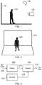
- Figures 1 and 2 schematically illustrate a so-called chroma key compositing (or colour shift overlay) image capture operation, as one example of a technique suitable for detecting an individual in a video scene or image.
- a subject 100 such as an individual actor is positioned in front of a coloured background 110 often referred to as a "green screen" (though it is noted that key colours other than green may be used; colours which tends not to occur in skin tones, such as green or blue, are considered useful for this purpose).
- the subject 100 is illuminated by one or more light sources shown schematically as light sources 120 (though the light source could be provided as, for example, a window to allow ambient light in) and images are captured by one or more cameras 130.
- the captured images will show the subject 100 against a green (or other predetermined key colour) background.
- regions or pixels formed of the key colour are identified and may be substituted by other image material, so that the subject 100 appears to be in front of or surrounded by the other image material.
- Figure 2 provides a front view of the same scene as Figure 1 , for example from the point of view of the camera 130.
- Figures 1 and 2 provide an example of the use of a background screen 110 of the predetermined key colour disposed so that an image subject is captured in front of the background screen; and a lighting arrangement 120 to illuminate the image subject.
- Figure 3 schematically illustrates an image processing apparatus configured to receive an input image 300, for example an image captured of the scene shown in Figures 1 and 2 , to apply chroma key compositing, and thus to generate an output image 310 representing the subject 100 in front of a substitute applied background.
- an input image 300 for example an image captured of the scene shown in Figures 1 and 2
- chroma key compositing and thus to generate an output image 310 representing the subject 100 in front of a substitute applied background.
- a detector 320 detects image positions at which the key colour is present in the captured input image 300 and generates an output 325 representing those portions of the input image 300 other than portions at which the key colour is present.
- a background generator 330 generates a background 335 which is provided, along with the output 325 of the detector 320, to a processor 340 which combines the signal 325 with the background 335 to generate the output image 310 representing the subject 100 in front of the substitute applied background 335.
- the signal 325 can be a so-called mask indicating portions of the input image 300 at which the key colour is detected to be present or not present, and the processor (which would also receive the input image in this arrangement) uses the mask to select between the input image 300 and the replacement background 335 on a pixel by pixel basis.
- Embodiments of the present disclosure relate to arrangements in which captured video sequences may need to be presented to a viewer in a potentially non-linear fashion.
- such arrangements can relate to non-linear movies or to video games in which the storyline reflected by the video sequence may branch depending upon various interactions provided by the viewer.
- the video sequence may be embodied in a video programme product such as a computer game product, and the user interactions may be for example video game interactions.
- the video sequence may be a stereoscopic video sequence reproducible by, for example, a head mountable display (HMD).
- the video programme product may be a stereoscopic video programme product.
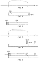
- a video sequence is captured according to the passage of time as represented by a horizontal axis. Because of the potential non-linear branching of the video storyline, it may be that at a point t 2 the display of the video sequence branches back to a time point t 1 . Note that the branching is dependent upon viewer interaction so it may happen or it may not happen.
- the second (potentially branching) time point t 2 is later in time, with respect to the input video signal, than the reference (branch target) time point t 1 .
- an unshaded block 500 represents a video sequence captured between the times t 1 and t 2
- a transitional sequence 510 is appended to the video sequence 500.
- the actor's pose is transitioned from the actor's pose at the time t 2 into the actor's pose at the time t 1 . So, in order to execute the non-linear flow from the time t 2 to the time t 1 as captured, first the transitional sequence 510 is displayed or presented to the viewer and then display resumes from the video sequence at the time t 1 .
- a transitional sequence 520 precedes the video sequence 500 so that on transitioning from the time t 2 in the captured video to the time t 1 in the captured video, first the transitional sequence 520 is displayed to return the actor's pose to the pose at the captured time t 1 , and then the video sequence 500 is played.
- Figures 7 to 9 show a similar arrangement but one in which the non-linear flow is such that potentially the display of the video sequence can selectively (under control of a user interaction for example) jump forward from the time t 1 from the time t 2 .
- the re-entry point or branch target can be the start 800 of a transitional sequence 810 which transitions the actor's pose from the pose held at t 1 to the pose held at t 2 with replay then continuing 820 from t 2 onwards.
- a transitional sequence 900 can be replayed before the transition 910 to the time t 2 is effected.
- a reference pose is detected at the non-linear jump target (t 1 in Figure 4 , t 2 in Figure 7 ) and differences between a second pose (at t 2 in Figure 4 or t 1 in Figure 7 ) and the respective reference pose are used to generate the respective transitional sequence which is then combined with the captured video to allow for such non-linear transitions.
- the transitional video sequence can be associated with the second time point or with the reference time point.
- Each of these involves a non-liner replay branch (either backwards or forwards) from the second time point to the reference time point, and the use of the transitional video sequence allows for a transition in pose without including subjectively disturbing pose discontinuities.
- the output video sequence includes at least the transitional video sequence (500, 510, 800, 900) in each case. In some examples (such as those relating to backward branches) it also includes a portion of the input video sequence.
- the arrangement allows for the implementation of replay including the non-linear replay branch with a continuous or substantially continuous pose of the individual.
- continuous may be taken to mean that pose discontinuities (variations in position of any limb or segment) at or caused by the transition are less than a threshold amount. The same threshold will be discussed below in connection with the selection of a number of intermediate images or frames for the transitional video sequence.
- Figures 10a-10c schematically represent a version of the arrangement of Figures 1 and 2 in which a subject 1000 is captured in a video image in front of a chroma key screen 1010.
- Figure 10b is a representation of the signal 325 generated by the detector 320 in which portions of the captured image formed of the key colour are removed.
- the chroma key masking is used to remove non-subject background and so to facilitate the generation of pose information.
- the remaining image portion relating only to the subject 1000 is processed to generate a skeletal (otherwise colloquially referred to as a stick-man) pose representation 1020.
- Segments 1030 represent respective limbs or limb portions.
- chroma key technique discussed above is just one way of detecting the presence of the individual in the video images and its use is not essential.
- Other possible techniques to implement a step of detecting an individual as part of detecting a reference or other pose may include using stereoscopic image capture or other image capture providing a depth indication (such as image capture using so-called "structured light” in which a grid or other pattern of light, for example infra-red light, is projected onto the scene to be captured so that images which detect the structured light, such as infra-red images, can detect depth from distortions of the structured light pattern) and detecting the presence of the individual in response to the depth detections so as to distinguish background (greater depth) from individual (lesser depth).
- Another possible technique involves using artificial intelligence, for example so-called deep learning techniques.
- Another possible technique involves manual subject extraction using so-called rotoscoping.
- a pose detector P provided as a trained artificial neural network (ANN) generates the skeletal representation from video frames of a subject.
- ANN trained artificial neural network
- a pose detector 1100 is responsive to the signal 325 and/or the input image 300 to generate the skeletal pose representation 1110 for a particular image.
- the particular images for which such a pose is generated are the images at the times t 1 and t 2 discussed above, one of these being a reference image position (at the branch target of the potential non-linear video programme flow branch) and the other being a second image at the branching point in the non-linear video programme flow.
- the skeletal pose for each of the reference and second images are provided ( Figure 12 ) to a pose interpolator 1200.
- This detects limb-by-limb (or limb portion by limb portion, in other word segment by segment) differences in the respective poses and generates a series 1210 of intermediate poses so as to provide a smooth transition from one to the other of the second poses.
- the transition is from the second pose to the reference pose.
- the number of intermediate poses can depend upon the magnitude of difference between the two input poses. If each limb or segment needs to move only a small amount between the two poses, a smaller number of intermediate skeletal poses can be generated. If there is a more significant movement between the two poses, more intermediate poses may be required.
- the aim of the pose interpolator is that, from one pose to the next, a sufficiently small movement of any individual limb or segment takes place that the movement does not look jerky or unnatural when later transformed back to successive image videos.
- generating the transitional video sequence comprises selecting a number of frames for the transitional video sequence so as not to exceed a threshold maximum pose change of any portion of the individual (for example, one or both of an angular or lateral threshold of inter-frame motion of a limb, limb portion or segment) between successive frames.
- the step of generating the transitional video sequence can comprise selecting a number of frames for the transitional video sequence in response the magnitude of difference between the second pose and the reference pose so as to provide sufficient intermediate poses that each limb or segment of the individual does not exceed a threshold maximum pose change between successive frames.
- the intermediate poses are provided to a frame generator 1220 which is responsive to source images 1230 captured of the subject and uses techniques described under the heading of "transfer" in the Chan paper to generate animated frames or images of the subject based on the captured source images 1230, each frame representing a respective intermediate pose. So, the combination of the successive frames representing the intermediate poses provides a transition or linkage between the second pose and the reference pose as a video output transitional sequence 1240 for use as any of the transitional sequences 510, 520 810, 900 discussed above.
- Figure 13-16 provide a worked example of this process.
- Figure 13 represents captured images relating to the second (branch point) 1300 and reference (branch target) 1310 positions in the captured video sequence.
- a skeletal pose 1400 is generated by the pose detector 1100 for the second pose and a skeletal pose 1410 is generated by the pose detector 1100 for the reference pose. This provides an example of detecting a reference skeletal pose 1410 of the individual at the reference time point; and detecting a second skeletal pose 1400 of the individual at the second time point.
- the pose interpolator 1200 detects differences between these two skeletal poses and interpolates a set of intermediate poses 1210 between the two.
- the frame generator 1220 generates respective intermediate frames or images 1500, 1510 from the source images 1230 (a library of example images of the individual or actor as discussed in the Chan paper) corresponding to each of the intermediate skeletal poses 1210.
- the result is the intermediate video sequence 1240 providing a transition between the second image 1300 and the reference image 1310 so that in the case of a selectable non-linear branch or transition in the replayed video from the second frame to the reference frame, the transitional sequence 1240 can be replayed so as to provide a smooth transition to the reference pose.
- Figures 14 to 16 provides an example of generating a sequence 1210 of skeletal representations which transition from the reference skeletal pose to the second skeletal pose; and generating respective video images 1240 of the individual for each of the sequence of skeletal representations in dependence upon the one or more source images.
- Figure 17 schematically illustrates a video processing apparatus comprising:
- Figure 18 is a schematic flowchart illustrating a video processing method comprising:
- Figure 20 schematically illustrates a data processing apparatus suitable to carry out the methods discussed above and in particular to implement one or both of the auto-encoder and the classification system, comprising a central processing unit or CPU 2000, a random access memory (RAM) 2010, a non-transitory machine-readable memory or medium (NTMRM) 2020 such as a flash memory, a hard disc drive or the like, a user interface such as a display, keyboard, mouse, or the like 2030, and an input/output interface 2040. These components are linked together by a bus structure 2050.
- the CPU 2000 can perform any of the above methods under the control of program instructions stored in the RAM 2010 and/or the NTMRM 2020.
- the NTMRM 2020 therefore provides an example of a non-transitory machine-readable medium which stores computer software by which the CPU 2000 perform the method or methods discussed above.
- a non-transitory machine-readable medium carrying such software such as an optical disk, a magnetic disk, semiconductor memory or the like, is also considered to represent an embodiment of the present disclosure.
- a data signal comprising coded data generated according to the methods discussed above (whether or not embodied on a non-transitory machine-readable medium) is also considered to represent an embodiment of the present disclosure.
Landscapes
- Engineering & Computer Science (AREA)
- Physics & Mathematics (AREA)
- Theoretical Computer Science (AREA)
- General Physics & Mathematics (AREA)
- Computer Vision & Pattern Recognition (AREA)
- Multimedia (AREA)
- Human Computer Interaction (AREA)
- Signal Processing (AREA)
- Health & Medical Sciences (AREA)
- Social Psychology (AREA)
- Psychiatry (AREA)
- General Health & Medical Sciences (AREA)
- Processing Or Creating Images (AREA)
Abstract
Description
- This disclosure relates to video processing methods and apparatus.
- The "background" description provided herein is for the purpose of generally presenting the context of the disclosure. Work of the presently named inventors, to the extent it is described in this background section, as well as aspects of the description which may not otherwise qualify as prior art at the time of filing, is neither expressly or impliedly admitted as prior art against the present disclosure.
- Some video programme products, such as video game products or non-linear movie products, allow for non-linear video replay branches in dependence upon user interactions or other inputs.
- The present disclosure provides a video processing method comprising:
- detecting, as a reference pose, a pose of an individual at a reference time point in an input video sequence;
- at a second, different, time point in the input video sequence, detecting a second pose of the individual;
- generating from one or more source images of the individual, a transitional video sequence representing a transition of the individual from the second pose to the reference pose; and
- associating the transitional video sequence with the input video sequence to generate an output video sequence including at least the transitional video sequence to implement a non-linear replay branch from the second time point to the reference time point.
- The present disclosure also provides a method of generating a video programme product, the method comprising:
- generating one or more output video sequences as defined above;
- generating control signals defining transitions between the output video sequences in dependence upon user interactions during reproduction of the video programme product.
- The present disclosure also provides video processing apparatus comprising:
- a detector configured to detect, as a reference pose, a pose of an individual at a reference time point in an input video sequence and to detect, at a second, different, time point in the input video sequence, a second pose of the individual;
- a generator configured to generate from one or more source images of the individual, a transitional video sequence representing a transition of the individual from the second pose to the reference pose; and
- a processor to associate the transitional video sequence with the input video sequence to generate an output video sequence including at least the transitional video sequence to implement a non-linear replay branch from the second time point to the reference time point.
- Further respective aspects and features of the present disclosure are defined in the associated claims.
- It is to be understood that both the foregoing general description and the following detailed description are exemplary, but are not restrictive, of the present technology.
- A more complete appreciation of the disclosure and many of the attendant advantages thereof will be readily obtained as the same becomes better understood by reference to the following detailed description when considered in connection with the accompanying drawings, in which:
-
Figures 1 and 2 schematically illustrate a chroma key compositing image capture operation; -
Figure 3 schematically illustrates an image processing apparatus; -
Figures 4 to 9 schematically illustrate the use of transitional sequences in non-linear video transitions; -
Figures 10a to 10c schematically illustrate a pose detection process; -
Figure 11 schematically illustrates a pose detector; -
Figure 12 schematically illustrates a transitional sequence generator; -
Figures 13 to 16 provide schematic diagrams illustrating stages in the generation of a transitional sequence; -
Figure 17 schematically illustrates an apparatus; -
Figures 18 and 19 are schematic flowcharts illustrating respective methods; and -
Figure 20 schematically illustrates a data processing apparatus. - Referring now to the drawings,
Figures 1 and 2 schematically illustrate a so-called chroma key compositing (or colour shift overlay) image capture operation, as one example of a technique suitable for detecting an individual in a video scene or image. - Here, a
subject 100 such as an individual actor is positioned in front of acoloured background 110 often referred to as a "green screen" (though it is noted that key colours other than green may be used; colours which tends not to occur in skin tones, such as green or blue, are considered useful for this purpose). Thesubject 100 is illuminated by one or more light sources shown schematically as light sources 120 (though the light source could be provided as, for example, a window to allow ambient light in) and images are captured by one ormore cameras 130. - The captured images will show the
subject 100 against a green (or other predetermined key colour) background. In subsequent image processing, regions or pixels formed of the key colour are identified and may be substituted by other image material, so that thesubject 100 appears to be in front of or surrounded by the other image material. -
Figure 2 provides a front view of the same scene asFigure 1 , for example from the point of view of thecamera 130. - Therefore
Figures 1 and 2 provide an example of the use of abackground screen 110 of the predetermined key colour disposed so that an image subject is captured in front of the background screen; and alighting arrangement 120 to illuminate the image subject. -
Figure 3 schematically illustrates an image processing apparatus configured to receive aninput image 300, for example an image captured of the scene shown inFigures 1 and 2 , to apply chroma key compositing, and thus to generate anoutput image 310 representing thesubject 100 in front of a substitute applied background. - Returning to
Figure 3 , adetector 320 detects image positions at which the key colour is present in the capturedinput image 300 and generates anoutput 325 representing those portions of theinput image 300 other than portions at which the key colour is present. Abackground generator 330 generates abackground 335 which is provided, along with theoutput 325 of thedetector 320, to aprocessor 340 which combines thesignal 325 with thebackground 335 to generate theoutput image 310 representing thesubject 100 in front of the substitute appliedbackground 335. - In other arrangements the
signal 325 can be a so-called mask indicating portions of theinput image 300 at which the key colour is detected to be present or not present, and the processor (which would also receive the input image in this arrangement) uses the mask to select between theinput image 300 and thereplacement background 335 on a pixel by pixel basis. - Embodiments of the present disclosure relate to arrangements in which captured video sequences may need to be presented to a viewer in a potentially non-linear fashion. For example, such arrangements can relate to non-linear movies or to video games in which the storyline reflected by the video sequence may branch depending upon various interactions provided by the viewer. For example, the video sequence may be embodied in a video programme product such as a computer game product, and the user interactions may be for example video game interactions.
- In at least some examples, the video sequence may be a stereoscopic video sequence reproducible by, for example, a head mountable display (HMD). In such examples the video programme product may be a stereoscopic video programme product.
- Referring to
Figure 4 , a video sequence is captured according to the passage of time as represented by a horizontal axis. Because of the potential non-linear branching of the video storyline, it may be that at a point t2 the display of the video sequence branches back to a time point t1. Note that the branching is dependent upon viewer interaction so it may happen or it may not happen. - In order to avoid subjectively disturbing discontinuities in the appearance of the actor or actors involved, it is desirable that at least the actor's pose is the same at the time points t1 and t2. In previously proposed arrangements, this would require the actor to physically return to the pose that they previously occupied at t1 so as to resume the same pose at t2. This is actually quite a difficult and potentially uncomfortable thing for an actor to have to do, and may be only partially successful even if the actor attempts it.
- In
Figure 4 , the second (potentially branching) time point t2 is later in time, with respect to the input video signal, than the reference (branch target) time point t1. - Referring to
Figures 5 and 6 , assuming that anunshaded block 500 represents a video sequence captured between the times t1 and t2, in some example embodiments atransitional sequence 510 is appended to thevideo sequence 500. In the transitional sequence the actor's pose is transitioned from the actor's pose at the time t2 into the actor's pose at the time t1. So, in order to execute the non-linear flow from the time t2 to the time t1 as captured, first thetransitional sequence 510 is displayed or presented to the viewer and then display resumes from the video sequence at the time t1. - In another arrangement shown in
Figure 6 , atransitional sequence 520 precedes thevideo sequence 500 so that on transitioning from the time t2 in the captured video to the time t1 in the captured video, first thetransitional sequence 520 is displayed to return the actor's pose to the pose at the captured time t1, and then thevideo sequence 500 is played. -
Figures 7 to 9 show a similar arrangement but one in which the non-linear flow is such that potentially the display of the video sequence can selectively (under control of a user interaction for example) jump forward from the time t1 from the time t2. Referring toFigure 8 , if such a jump takes place, the re-entry point or branch target can be thestart 800 of atransitional sequence 810 which transitions the actor's pose from the pose held at t1 to the pose held at t2 with replay then continuing 820 from t2 onwards. Alternatively, as shown inFigure 9 , if such a branch is triggered, atransitional sequence 900 can be replayed before thetransition 910 to the time t2 is effected. - In each of these cases, a reference pose is detected at the non-linear jump target (t1 in
Figure 4 , t2 inFigure 7 ) and differences between a second pose (at t2 inFigure 4 or t1 inFigure 7 ) and the respective reference pose are used to generate the respective transitional sequence which is then combined with the captured video to allow for such non-linear transitions. It can be seen that inFigures 5, 6, 8 and 9 , the transitional video sequence can be associated with the second time point or with the reference time point. - Therefore, in summary of these arrangements reference is made to the following table:
reference time point second time point non-linear branch Output video sequence Figs 4 and 5 t1 t2 from t2 to t1 500 then 510 Figs 4 and 6 t1 t2 from t2 to t1 520 then 500 Figs 7 and 8 t2 t1 from t1 to t2 800 Figs 7 and 9 t2 t1 from t1 to t2 900 - Each of these involves a non-liner replay branch (either backwards or forwards) from the second time point to the reference time point, and the use of the transitional video sequence allows for a transition in pose without including subjectively disturbing pose discontinuities.
- The output video sequence includes at least the transitional video sequence (500, 510, 800, 900) in each case. In some examples (such as those relating to backward branches) it also includes a portion of the input video sequence.
- The arrangement allows for the implementation of replay including the non-linear replay branch with a continuous or substantially continuous pose of the individual. In this context, "continuous" may be taken to mean that pose discontinuities (variations in position of any limb or segment) at or caused by the transition are less than a threshold amount. The same threshold will be discussed below in connection with the selection of a number of intermediate images or frames for the transitional video sequence.
- Note that the same arrangement can be used to provide a branch reply from one video sequence to another, particularly where the same individual appears in the original and target sequences.
-
Figures 10a-10c schematically represent a version of the arrangement ofFigures 1 and 2 in which a subject 1000 is captured in a video image in front of achroma key screen 1010.Figure 10b is a representation of thesignal 325 generated by thedetector 320 in which portions of the captured image formed of the key colour are removed. The chroma key masking is used to remove non-subject background and so to facilitate the generation of pose information. InFigure 10c the remaining image portion relating only to the subject 1000, is processed to generate a skeletal (otherwise colloquially referred to as a stick-man) poserepresentation 1020.Segments 1030 represent respective limbs or limb portions. - Note that the chroma key technique discussed above is just one way of detecting the presence of the individual in the video images and its use is not essential. Other possible techniques to implement a step of detecting an individual as part of detecting a reference or other pose may include using stereoscopic image capture or other image capture providing a depth indication (such as image capture using so-called "structured light" in which a grid or other pattern of light, for example infra-red light, is projected onto the scene to be captured so that images which detect the structured light, such as infra-red images, can detect depth from distortions of the structured light pattern) and detecting the presence of the individual in response to the depth detections so as to distinguish background (greater depth) from individual (lesser depth). Another possible technique involves using artificial intelligence, for example so-called deep learning techniques. Another possible technique involves manual subject extraction using so-called rotoscoping.
- The generation of such skeletal poses can (as an example) use techniques disclosed in the paper "Everybody Dance Now" (Chan et al) incorporated herein by reference and published in August 2018 at the location: https://arxiv.org/pdf/1808.07371.pdf
- In the Chan paper, a pose detector P, provided as a trained artificial neural network (ANN) generates the skeletal representation from video frames of a subject. Technical details of how this is achieved are disclosed by the Chan paper.
- Such an arrangement is shown schematically in
Figure 11 , in which apose detector 1100 is responsive to thesignal 325 and/or theinput image 300 to generate theskeletal pose representation 1110 for a particular image. In the present examples, the particular images for which such a pose is generated are the images at the times t1 and t2 discussed above, one of these being a reference image position (at the branch target of the potential non-linear video programme flow branch) and the other being a second image at the branching point in the non-linear video programme flow. - The skeletal pose for each of the reference and second images are provided (
Figure 12 ) to apose interpolator 1200. This detects limb-by-limb (or limb portion by limb portion, in other word segment by segment) differences in the respective poses and generates aseries 1210 of intermediate poses so as to provide a smooth transition from one to the other of the second poses. In particular, given that the reference pose relates to the branch target in the program flow, the transition is from the second pose to the reference pose. The number of intermediate poses can depend upon the magnitude of difference between the two input poses. If each limb or segment needs to move only a small amount between the two poses, a smaller number of intermediate skeletal poses can be generated. If there is a more significant movement between the two poses, more intermediate poses may be required. The aim of the pose interpolator is that, from one pose to the next, a sufficiently small movement of any individual limb or segment takes place that the movement does not look jerky or unnatural when later transformed back to successive image videos. In at least some example, generating the transitional video sequence comprises selecting a number of frames for the transitional video sequence so as not to exceed a threshold maximum pose change of any portion of the individual (for example, one or both of an angular or lateral threshold of inter-frame motion of a limb, limb portion or segment) between successive frames. - Therefore, the selection of a number of intermediate frames or images can be dealt with as follows: the step of generating the transitional video sequence can comprise selecting a number of frames for the transitional video sequence in response the magnitude of difference between the second pose and the reference pose so as to provide sufficient intermediate poses that each limb or segment of the individual does not exceed a threshold maximum pose change between successive frames.
- The intermediate poses are provided to a
frame generator 1220 which is responsive to sourceimages 1230 captured of the subject and uses techniques described under the heading of "transfer" in the Chan paper to generate animated frames or images of the subject based on the capturedsource images 1230, each frame representing a respective intermediate pose. So, the combination of the successive frames representing the intermediate poses provides a transition or linkage between the second pose and the reference pose as a video outputtransitional sequence 1240 for use as any of thetransitional sequences -
Figure 13-16 provide a worked example of this process. In particular,Figure 13 represents captured images relating to the second (branch point) 1300 and reference (branch target) 1310 positions in the captured video sequence. - In
Figure 14 , askeletal pose 1400 is generated by thepose detector 1100 for the second pose and askeletal pose 1410 is generated by thepose detector 1100 for the reference pose. This provides an example of detecting a referenceskeletal pose 1410 of the individual at the reference time point; and detecting a secondskeletal pose 1400 of the individual at the second time point. - The
pose interpolator 1200 detects differences between these two skeletal poses and interpolates a set ofintermediate poses 1210 between the two. In the example ofFigure 14 , there are two intermediate poses which provide sufficient variation, pose-to-pose to allow a smooth transition between theskeletal pose 1400 and theskeletal pose 1410. From pose to pose, there areincremental movements 1420 in the two upper limbs, being the limbs for which differences are detected between thepose 1400 and thepose 1410. - In
Figure 15 , theframe generator 1220 generates respective intermediate frames orimages skeletal poses 1210. - The result is the
intermediate video sequence 1240 providing a transition between thesecond image 1300 and thereference image 1310 so that in the case of a selectable non-linear branch or transition in the replayed video from the second frame to the reference frame, thetransitional sequence 1240 can be replayed so as to provide a smooth transition to the reference pose. - Therefore, the process illustrated in
Figures 14 to 16 provides an example of generating asequence 1210 of skeletal representations which transition from the reference skeletal pose to the second skeletal pose; and generatingrespective video images 1240 of the individual for each of the sequence of skeletal representations in dependence upon the one or more source images. - By way of summary and making use of the techniques described here,
Figure 17 schematically illustrates a video processing apparatus comprising: - a
detector 1700 configured to detect, as a reference pose, a pose of an individual at a reference time point in an input video sequence and to detect, at a second, different, time point in the input video sequence, a second pose of the individual; - a
generator 1710 configured to generate from one or more source images of the individual, a transitional video sequence representing a transition of the individual from the second pose to the reference pose; and - a
processor 1720 configured to associate the transitional video sequence with the input video sequence to generate an output video sequence including at least the transitional video sequence to implement a non-linear replay branch from the second time point to the reference time point. -
Figure 18 is a schematic flowchart illustrating a video processing method comprising: - detecting (at a step 1800), as a reference pose, a pose of an individual at a reference time point in an input video sequence;
- at a second, different, time point in the input video sequence, detecting (at a step 1810) a second pose of the individual;
- generating (at a step 1820) from one or more source images of the individual, a transitional video sequence representing a transition of the individual from the second pose to the reference pose; and
- associating (at a step 1830) the transitional video sequence with the input video sequence to generate an output video sequence including at least the transitional video sequence to implement a non-linear replay branch from the second time point to the reference time point.
-
Figure 19 is a further schematic flowchart illustrating a method of generating a video programme product, the method comprising:- generating (at a step 1900) one or more output video sequences according to
Figure 18 or variants of that method as discussed here; and - generating (at a step 1910) control signals defining transitions between the output video sequences in dependence upon user interactions during reproduction of the video programme product.
- generating (at a step 1900) one or more output video sequences according to
-
Figure 20 schematically illustrates a data processing apparatus suitable to carry out the methods discussed above and in particular to implement one or both of the auto-encoder and the classification system, comprising a central processing unit orCPU 2000, a random access memory (RAM) 2010, a non-transitory machine-readable memory or medium (NTMRM) 2020 such as a flash memory, a hard disc drive or the like, a user interface such as a display, keyboard, mouse, or the like 2030, and an input/output interface 2040. These components are linked together by abus structure 2050. TheCPU 2000 can perform any of the above methods under the control of program instructions stored in theRAM 2010 and/or theNTMRM 2020. TheNTMRM 2020 therefore provides an example of a non-transitory machine-readable medium which stores computer software by which theCPU 2000 perform the method or methods discussed above. - In so far as embodiments of the disclosure have been described as being implemented, at least in part, by software-controlled data processing apparatus, it will be appreciated that a non-transitory machine-readable medium carrying such software, such as an optical disk, a magnetic disk, semiconductor memory or the like, is also considered to represent an embodiment of the present disclosure. Similarly, a data signal comprising coded data generated according to the methods discussed above (whether or not embodied on a non-transitory machine-readable medium) is also considered to represent an embodiment of the present disclosure.
- It will be apparent that numerous modifications and variations of the present disclosure are possible in light of the above teachings. It is to be understood that the disclosure is defined by the appended claims.
Claims (13)
- A video processing method comprising:detecting, as a reference pose, a pose of an individual at a reference time point in an input video sequence;at a second, different, time point in the input video sequence, detecting a second pose of the individual;generating from one or more source images of the individual, a transitional video sequence representing a transition of the individual from the second pose to the reference pose; andassociating the transitional video sequence with the input video sequence to generate an output video sequence including at least the transitional video sequence to implement a non-linear replay branch from the second time point to the reference time point.
- A method according to claim 1, in which:the step of detecting the reference pose comprises detecting a reference skeletal pose of the individual at the reference time point; andthe step of detecting the second pose comprises detecting a second skeletal pose of the individual at the second time point.
- A method according to claim 2, in which the generating step comprises:generating a sequence of skeletal representations which transition from the reference skeletal pose to the second skeletal pose; andgenerating respective video images of the individual for each of the sequence of skeletal representations in dependence upon the one or more source images.
- A method according to any one of claims 1 to 3, in which the second time point is later in time, with respect to the input video signal, than the reference time point.
- A method according to any one of the preceding claims, in which the associating step comprises associating the transitional video sequence with the second time point.
- A method according to any one of the preceding claims, in which the associating step comprises associating the transitional video sequence with the reference time point.
- A method according to any one of the preceding claims, in which the step of generating the transitional video sequence comprises selecting a number of frames for the transitional video sequence in response the magnitude of difference between the second pose and the reference pose so as to provide sufficient intermediate poses that each limb or segment of the individual does not exceed a threshold maximum pose change between successive frames.
- A method of generating a video programme product, the method comprising:generating one or more output video sequences according to any one of the preceding claims;generating control signals defining transitions between the output video sequences in dependence upon user interactions during reproduction of the video programme product.
- A method according to claim 8, in which the video programme product is a computer game product, and the user interactions are video game interactions.
- A method according to claim 8 or claim 9, in which the video programme product is a stereoscopic video programme product.
- Computer software comprising program instructions which, when executed by a computer, cause the computer to perform the method of any one of the preceding claims.
- A non-transitory machine-readable storage medium which stores computer software according to claim 11.
- Video processing apparatus comprising:a detector configured to detect, as a reference pose, a pose of an individual at a reference time point in an input video sequence and to detect, at a second, different, time point in the input video sequence, a second pose of the individual;a generator configured to generate from one or more source images of the individual, a transitional video sequence representing a transition of the individual from the second pose to the reference pose; anda processor to associate the transitional video sequence with the input video sequence to generate an output video sequence including at least the transitional video sequence to implement a non-linear replay branch from the second time point to the reference time point.
Applications Claiming Priority (2)
| Application Number | Priority Date | Filing Date | Title |
|---|---|---|---|
| GB1905351.1A GB2583101B (en) | 2019-04-16 | 2019-04-16 | Video processing |
| GBGB1915894.8A GB201915894D0 (en) | 2019-04-16 | 2019-11-01 | Video processing |
Publications (2)
| Publication Number | Publication Date |
|---|---|
| EP3726470A1 true EP3726470A1 (en) | 2020-10-21 |
| EP3726470B1 EP3726470B1 (en) | 2026-03-04 |
Family
ID=66810068
Family Applications (1)
| Application Number | Title | Priority Date | Filing Date |
|---|---|---|---|
| EP20168385.1A Active EP3726470B1 (en) | 2019-04-16 | 2020-04-07 | Video processing |
Country Status (3)
| Country | Link |
|---|---|
| US (1) | US11276196B2 (en) |
| EP (1) | EP3726470B1 (en) |
| GB (2) | GB2583101B (en) |
Families Citing this family (8)
| Publication number | Priority date | Publication date | Assignee | Title |
|---|---|---|---|---|
| WO2022251671A1 (en) * | 2021-05-27 | 2022-12-01 | Ai Thinktank Llc | 3d avatar generation and robotic limbs using biomechanical analysis |
| US12008839B2 (en) | 2021-05-28 | 2024-06-11 | Sportsbox.ai Inc. | Golf club and other object fitting using quantitative biomechanical-based analysis |
| US11615648B2 (en) | 2021-05-28 | 2023-03-28 | Sportsbox.ai Inc. | Practice drill-related features using quantitative, biomechanical-based analysis |
| CN116934911A (en) * | 2022-04-12 | 2023-10-24 | 腾讯科技(深圳)有限公司 | Image sequence processing method, device, computer equipment and storage medium |
| USD1035720S1 (en) | 2022-04-20 | 2024-07-16 | Sportsbox.ai Inc. | Display screen with transitional graphical user interface |
| USD1035721S1 (en) | 2022-04-20 | 2024-07-16 | Sportsbox.ai Inc. | Display screen with transitional graphical user interface |
| USD1107052S1 (en) | 2022-04-20 | 2025-12-23 | Sportsbox.ai Inc. | Display screen with transitional graphical user interface |
| USD1036464S1 (en) | 2022-04-20 | 2024-07-23 | Sportsbox.ai Inc. | Display screen with transitional graphical user interface |
Citations (1)
| Publication number | Priority date | Publication date | Assignee | Title |
|---|---|---|---|---|
| US20140071287A1 (en) * | 2012-09-13 | 2014-03-13 | General Electric Company | System and method for generating an activity summary of a person |
Family Cites Families (12)
| Publication number | Priority date | Publication date | Assignee | Title |
|---|---|---|---|---|
| US6600491B1 (en) * | 2000-05-30 | 2003-07-29 | Microsoft Corporation | Video-based rendering with user-controlled movement |
| JP4486594B2 (en) * | 2002-11-07 | 2010-06-23 | 本田技研工業株式会社 | Video-based face recognition using probabilistic appearance aggregates |
| US8406569B2 (en) * | 2009-01-19 | 2013-03-26 | Sharp Laboratories Of America, Inc. | Methods and systems for enhanced dynamic range images and video from multiple exposures |
| AU2011265430B2 (en) * | 2011-12-21 | 2015-03-19 | Canon Kabushiki Kaisha | 3D reconstruction of partially unobserved trajectory |
| US9058663B2 (en) * | 2012-04-11 | 2015-06-16 | Disney Enterprises, Inc. | Modeling human-human interactions for monocular 3D pose estimation |
| US9322653B2 (en) * | 2013-01-16 | 2016-04-26 | Disney Enterprises, Inc. | Video-based motion capture and adaptation |
| EP2787741A1 (en) * | 2013-04-05 | 2014-10-08 | Nederlandse Organisatie voor toegepast -natuurwetenschappelijk onderzoek TNO | Video processing system and method |
| US9754399B2 (en) * | 2014-07-17 | 2017-09-05 | Crayola, Llc | Customized augmented reality animation generator |
| US10061987B2 (en) * | 2016-11-11 | 2018-08-28 | Google Llc | Differential scoring: a high-precision scoring method for video matching |
| US10824918B2 (en) * | 2017-01-31 | 2020-11-03 | Stats Llc | System and method for predictive sports analytics using body-pose information |
| US11182597B2 (en) * | 2018-01-19 | 2021-11-23 | Board Of Regents, The University Of Texas Systems | Systems and methods for evaluating individual, group, and crowd emotion engagement and attention |
| CN112654951A (en) * | 2018-09-27 | 2021-04-13 | 苹果公司 | Mobile head portrait based on real world data |
-
2019
- 2019-04-16 GB GB1905351.1A patent/GB2583101B/en active Active
- 2019-11-01 GB GBGB1915894.8A patent/GB201915894D0/en not_active Ceased
-
2020
- 2020-04-07 EP EP20168385.1A patent/EP3726470B1/en active Active
- 2020-04-15 US US16/849,118 patent/US11276196B2/en active Active
Patent Citations (1)
| Publication number | Priority date | Publication date | Assignee | Title |
|---|---|---|---|---|
| US20140071287A1 (en) * | 2012-09-13 | 2014-03-13 | General Electric Company | System and method for generating an activity summary of a person |
Non-Patent Citations (3)
| Title |
|---|
| ARNO SCH�DL ET AL: "Controlled animation of video sprites", ACM SIGGRAPH SYMPOSIUM ON COMPUTER ANIMATION. SAN ANTONIO, TX, JULY 21 - 22, 2002; [ACM SIGGRAPH SYMPOSIUM ON COMPUTER ANIMATION], ACM, NEW YORK, NY, 21 July 2002 (2002-07-21), pages 121 - 127, XP058171523, ISBN: 978-1-58113-573-2, DOI: 10.1145/545261.545281 * |
| CHAN ET AL., EVERYBODY DANCE NOW, August 2018 (2018-08-01), Retrieved from the Internet <URL:https://arxiv.ora/pdf/1808.07371.pdf> |
| JUAN DU ET AL: "3D Human Skeleton Synergy Kinematics Based on the Video", 2012 SYMPOSIUM ON PHOTONICS AND OPTOELECTRONICS, 1 May 2012 (2012-05-01), pages 1 - 4, XP055721369, ISSN: 2156-8464, ISBN: 978-1-4577-0910-4, DOI: 10.1109/SOPO.2012.6270504 * |
Also Published As
| Publication number | Publication date |
|---|---|
| EP3726470B1 (en) | 2026-03-04 |
| US20200334852A1 (en) | 2020-10-22 |
| GB2583101A (en) | 2020-10-21 |
| GB2583101B (en) | 2021-05-19 |
| GB201905351D0 (en) | 2019-05-29 |
| US11276196B2 (en) | 2022-03-15 |
| GB201915894D0 (en) | 2019-12-18 |
Similar Documents
| Publication | Publication Date | Title |
|---|---|---|
| US11276196B2 (en) | Video processing | |
| CN111540055B (en) | Three-dimensional model driving method, three-dimensional model driving device, electronic equipment and storage medium | |
| US20010052899A1 (en) | System and method for creating 3d models from 2d sequential image data | |
| US4258385A (en) | Interactive video production system and method | |
| US7149974B2 (en) | Reduced representations of video sequences | |
| US5519826A (en) | Stop motion animation system | |
| US20080019610A1 (en) | Image processing device and image processing method | |
| CN108184165B (en) | Video playback method, electronic device, and computer-readable storage medium | |
| WO2011028837A2 (en) | System and process for transforming two-dimensional images into three-dimensional images | |
| KR20160013984A (en) | Touch optimized design for video editing | |
| Rachavarapu et al. | Watch to edit: Video retargeting using gaze | |
| CA2866672A1 (en) | Motion picture project management system | |
| KR20140146592A (en) | Color grading preview method and apparatus | |
| CN114466232B (en) | Video processing method, device, electronic equipment and medium | |
| US20190327427A1 (en) | System for Producing Augmented Images | |
| JP2011155477A (en) | Video processing apparatus, video processing method, and program | |
| Dakss et al. | Hyperlinked video | |
| CN121509729A (en) | A method, apparatus, device, and storage medium for erasing video subtitles. | |
| US10832732B2 (en) | Television broadcast system for generating augmented images | |
| Gandhi et al. | A computational framework for vertical video editing | |
| US8855472B2 (en) | Video editing apparatus, video editing method, program, and integrated circuit | |
| US20200342619A1 (en) | Method and system for data encoding from media for mechanical output | |
| JP2009290828A (en) | Image processor, and image processing method | |
| KR102849590B1 (en) | Method and Apparatus for Replacing Subtitle | |
| CN114827477B (en) | Method, device, electronic equipment and medium for time-lapse photography |
Legal Events
| Date | Code | Title | Description |
|---|---|---|---|
| PUAI | Public reference made under article 153(3) epc to a published international application that has entered the european phase |
Free format text: ORIGINAL CODE: 0009012 |
|
| STAA | Information on the status of an ep patent application or granted ep patent |
Free format text: STATUS: REQUEST FOR EXAMINATION WAS MADE |
|
| 17P | Request for examination filed |
Effective date: 20200421 |
|
| AK | Designated contracting states |
Kind code of ref document: A1 Designated state(s): AL AT BE BG CH CY CZ DE DK EE ES FI FR GB GR HR HU IE IS IT LI LT LU LV MC MK MT NL NO PL PT RO RS SE SI SK SM TR |
|
| AX | Request for extension of the european patent |
Extension state: BA ME |
|
| STAA | Information on the status of an ep patent application or granted ep patent |
Free format text: STATUS: EXAMINATION IS IN PROGRESS |
|
| 17Q | First examination report despatched |
Effective date: 20240122 |
|
| GRAP | Despatch of communication of intention to grant a patent |
Free format text: ORIGINAL CODE: EPIDOSNIGR1 |
|
| STAA | Information on the status of an ep patent application or granted ep patent |
Free format text: STATUS: GRANT OF PATENT IS INTENDED |
|
| RIC1 | Information provided on ipc code assigned before grant |
Ipc: G06T 7/70 20170101AFI20250930BHEP Ipc: G06T 13/80 20110101ALI20250930BHEP Ipc: G06T 13/40 20110101ALI20250930BHEP Ipc: H04N 5/262 20060101ALI20250930BHEP |
|
| INTG | Intention to grant announced |
Effective date: 20251009 |
|
| GRAS | Grant fee paid |
Free format text: ORIGINAL CODE: EPIDOSNIGR3 |
|
| GRAA | (expected) grant |
Free format text: ORIGINAL CODE: 0009210 |
|
| STAA | Information on the status of an ep patent application or granted ep patent |
Free format text: STATUS: THE PATENT HAS BEEN GRANTED |
|
| AK | Designated contracting states |
Kind code of ref document: B1 Designated state(s): AL AT BE BG CH CY CZ DE DK EE ES FI FR GB GR HR HU IE IS IT LI LT LU LV MC MK MT NL NO PL PT RO RS SE SI SK SM TR |
|
| P01 | Opt-out of the competence of the unified patent court (upc) registered |
Free format text: CASE NUMBER: UPC_APP_0002594_3726470/2026 Effective date: 20260126 |
|
| REG | Reference to a national code |
Ref country code: CH Ref legal event code: F10 Free format text: ST27 STATUS EVENT CODE: U-0-0-F10-F00 (AS PROVIDED BY THE NATIONAL OFFICE) Effective date: 20260304 Ref country code: GB Ref legal event code: FG4D |
|
| REG | Reference to a national code |
Ref country code: DE Ref legal event code: R096 Ref document number: 602020067842 Country of ref document: DE |
|
| REG | Reference to a national code |
Ref country code: IE Ref legal event code: FG4D |
|
| REG | Reference to a national code |
Ref country code: NL Ref legal event code: FP |