EP3726456A1 - Information processing system - Google Patents
Information processing system Download PDFInfo
- Publication number
- EP3726456A1 EP3726456A1 EP18887305.3A EP18887305A EP3726456A1 EP 3726456 A1 EP3726456 A1 EP 3726456A1 EP 18887305 A EP18887305 A EP 18887305A EP 3726456 A1 EP3726456 A1 EP 3726456A1
- Authority
- EP
- European Patent Office
- Prior art keywords
- information
- processing system
- user
- information processing
- section
- Prior art date
- Legal status (The legal status is an assumption and is not a legal conclusion. Google has not performed a legal analysis and makes no representation as to the accuracy of the status listed.)
- Pending
Links
Images






Classifications
-
- G—PHYSICS
- G06—COMPUTING OR CALCULATING; COUNTING
- G06F—ELECTRIC DIGITAL DATA PROCESSING
- G06F3/00—Input arrangements for transferring data to be processed into a form capable of being handled by the computer; Output arrangements for transferring data from processing unit to output unit, e.g. interface arrangements
- G06F3/01—Input arrangements or combined input and output arrangements for interaction between user and computer
- G06F3/03—Arrangements for converting the position or the displacement of a member into a coded form
- G06F3/041—Digitisers, e.g. for touch screens or touch pads, characterised by the transducing means
- G06F3/042—Digitisers, e.g. for touch screens or touch pads, characterised by the transducing means by opto-electronic means
-
- A—HUMAN NECESSITIES
- A61—MEDICAL OR VETERINARY SCIENCE; HYGIENE
- A61B—DIAGNOSIS; SURGERY; IDENTIFICATION
- A61B5/00—Measuring for diagnostic purposes; Identification of persons
- A61B5/117—Identification of persons
- A61B5/1171—Identification of persons based on the shapes or appearances of their bodies or parts thereof
-
- G—PHYSICS
- G06—COMPUTING OR CALCULATING; COUNTING
- G06F—ELECTRIC DIGITAL DATA PROCESSING
- G06F21/00—Security arrangements for protecting computers, components thereof, programs or data against unauthorised activity
- G06F21/30—Authentication, i.e. establishing the identity or authorisation of security principals
- G06F21/31—User authentication
- G06F21/32—User authentication using biometric data, e.g. fingerprints, iris scans or voiceprints
-
- G—PHYSICS
- G06—COMPUTING OR CALCULATING; COUNTING
- G06F—ELECTRIC DIGITAL DATA PROCESSING
- G06F3/00—Input arrangements for transferring data to be processed into a form capable of being handled by the computer; Output arrangements for transferring data from processing unit to output unit, e.g. interface arrangements
- G06F3/01—Input arrangements or combined input and output arrangements for interaction between user and computer
- G06F3/03—Arrangements for converting the position or the displacement of a member into a coded form
- G06F3/041—Digitisers, e.g. for touch screens or touch pads, characterised by the transducing means
- G06F3/0412—Digitisers structurally integrated in a display
-
- G—PHYSICS
- G06—COMPUTING OR CALCULATING; COUNTING
- G06F—ELECTRIC DIGITAL DATA PROCESSING
- G06F3/00—Input arrangements for transferring data to be processed into a form capable of being handled by the computer; Output arrangements for transferring data from processing unit to output unit, e.g. interface arrangements
- G06F3/01—Input arrangements or combined input and output arrangements for interaction between user and computer
- G06F3/03—Arrangements for converting the position or the displacement of a member into a coded form
- G06F3/041—Digitisers, e.g. for touch screens or touch pads, characterised by the transducing means
- G06F3/0416—Control or interface arrangements specially adapted for digitisers
-
- G—PHYSICS
- G06—COMPUTING OR CALCULATING; COUNTING
- G06F—ELECTRIC DIGITAL DATA PROCESSING
- G06F3/00—Input arrangements for transferring data to be processed into a form capable of being handled by the computer; Output arrangements for transferring data from processing unit to output unit, e.g. interface arrangements
- G06F3/01—Input arrangements or combined input and output arrangements for interaction between user and computer
- G06F3/03—Arrangements for converting the position or the displacement of a member into a coded form
- G06F3/041—Digitisers, e.g. for touch screens or touch pads, characterised by the transducing means
- G06F3/042—Digitisers, e.g. for touch screens or touch pads, characterised by the transducing means by opto-electronic means
- G06F3/0425—Digitisers, e.g. for touch screens or touch pads, characterised by the transducing means by opto-electronic means using a single imaging device like a video camera for tracking the absolute position of a single or a plurality of objects with respect to an imaged reference surface, e.g. video camera imaging a display or a projection screen, a table or a wall surface, on which a computer generated image is displayed or projected
-
- G—PHYSICS
- G06—COMPUTING OR CALCULATING; COUNTING
- G06F—ELECTRIC DIGITAL DATA PROCESSING
- G06F3/00—Input arrangements for transferring data to be processed into a form capable of being handled by the computer; Output arrangements for transferring data from processing unit to output unit, e.g. interface arrangements
- G06F3/01—Input arrangements or combined input and output arrangements for interaction between user and computer
- G06F3/048—Interaction techniques based on graphical user interfaces [GUI]
- G06F3/0484—Interaction techniques based on graphical user interfaces [GUI] for the control of specific functions or operations, e.g. selecting or manipulating an object, an image or a displayed text element, setting a parameter value or selecting a range
- G06F3/04842—Selection of displayed objects or displayed text elements
-
- G—PHYSICS
- G06—COMPUTING OR CALCULATING; COUNTING
- G06T—IMAGE DATA PROCESSING OR GENERATION, IN GENERAL
- G06T1/00—General purpose image data processing
-
- G—PHYSICS
- G06—COMPUTING OR CALCULATING; COUNTING
- G06V—IMAGE OR VIDEO RECOGNITION OR UNDERSTANDING
- G06V40/00—Recognition of biometric, human-related or animal-related patterns in image or video data
- G06V40/10—Human or animal bodies, e.g. vehicle occupants or pedestrians; Body parts, e.g. hands
- G06V40/12—Fingerprints or palmprints
- G06V40/13—Sensors therefor
-
- G—PHYSICS
- G06—COMPUTING OR CALCULATING; COUNTING
- G06V—IMAGE OR VIDEO RECOGNITION OR UNDERSTANDING
- G06V40/00—Recognition of biometric, human-related or animal-related patterns in image or video data
- G06V40/10—Human or animal bodies, e.g. vehicle occupants or pedestrians; Body parts, e.g. hands
- G06V40/12—Fingerprints or palmprints
- G06V40/13—Sensors therefor
- G06V40/1318—Sensors therefor using electro-optical elements or layers, e.g. electroluminescent sensing
-
- G—PHYSICS
- G06—COMPUTING OR CALCULATING; COUNTING
- G06V—IMAGE OR VIDEO RECOGNITION OR UNDERSTANDING
- G06V40/00—Recognition of biometric, human-related or animal-related patterns in image or video data
- G06V40/70—Multimodal biometrics, e.g. combining information from different biometric modalities
-
- G—PHYSICS
- G06—COMPUTING OR CALCULATING; COUNTING
- G06V—IMAGE OR VIDEO RECOGNITION OR UNDERSTANDING
- G06V40/00—Recognition of biometric, human-related or animal-related patterns in image or video data
- G06V40/10—Human or animal bodies, e.g. vehicle occupants or pedestrians; Body parts, e.g. hands
- G06V40/15—Biometric patterns based on physiological signals, e.g. heartbeat, blood flow
Definitions
- the present invention relates to an information processing system.
- PTL 1 discloses an imaging device to obtain an optical image of a subject, particularly to an imaging device suitable for obtaining a fingerprint image for personal identification.
- a fingerprint at a fingertip may have low ridges depending on a person, and in such a case, a fingerprint reader is sometimes not capable of obtaining fingerprint image data, or even when being capable of obtaining, the obtained data is sometimes not clear.
- the imaging device in PTL 1, however, is supposed to achieve an object of the invention to "allow clear imaging of a subject" by providing a configuration of "an imaging device, configured to obtain an optical image of a subject (e.g., a fingertip) from below a contact surface that contacts the subject, wherein a light diffusing film to diffuse light is formed on the contact surface".
- PTL 2 discloses a contact sensor to sense a test object. Similar to the case of PTL 1 above, a fingerprint reader is sometimes not capable of obtaining fingerprint image data, or even when being capable of obtaining, the obtained data is sometimes not clear.
- the contact sensor in PTL 2 is supposed to achieve an object of the invention to "allow clear imaging of a subject" by providing a configuration of "a contact sensor, configured to sense a test object placed on a placement surface, wherein a liquid repellent coating is formed on the placement surface".
- the inventions described in PTLs 1 and 2 assume obtaining fingerprint image data in a limited area region of about a fingertip, for example a region of approximately 10 mm ⁇ 10 mm, and thus to obtain clear fingerprint image data at an arbitrary position in a large area region of, for example, 10 inches or more, the number of scanning lines for data detection becomes enormous and it is difficult to quickly obtain image data.
- read sensors have to be arranged in an array with a 50 ⁇ m pitch, and the number of drivers for horizontal and vertical scanning is 5940 ⁇ 4200 for A4 size and 8400 ⁇ 5940 for A3 size.
- Such a large number of drivers has to be driven to read a fingerprint one time, causing a problem that the time taken to obtain the entire data becomes longer.
- not all the data thus obtained is used for personal identification and the data used for personal identification is limited to the data in the region toughed by the fingertip and thus a large amount of data in the other regions turns out to be useless data not used for personal identification.
- reservation sites or electronic commerce sites may require personal identification every time a user selects a process of an important procedure, such as payment processing.
- the security of transactions is thus ensured by requiring personal identification every time processing an important procedure.
- a first aspect of the present invention provides an information processing system, including: an input section having a surface and configured to allow a user to contact or approximate a position specifier to the surface for information input; and a processing section configured to perform processing based on the information input to the input section, wherein the input section includes a position detection mechanism configured to detect a position of the position specifier on the surface and a reading mechanism configured to read biometric information of the user.
- the above information processing system may have a configuration in which the processing section narrows down a region to be read by the reading mechanism based on position information of the position specifier obtained from the position detection mechanism and activates the reading mechanism in the reading region to obtain the biometric information.
- the above information processing system may have another configuration in which the processing section configured to perform next processing based on position information of the position specifier obtained from the position detection mechanism and attribute information of the user associated with the biometric information obtained from the reading mechanism.
- the above information processing system may further include a display section 210 arranged facing the input section, wherein the processing section selects and performs, in the next processing, a function in accordance with the attribute information among functions assigned to the position of the display section 210 specified in the position information.
- the above information processing system may have a configuration in which the position detection mechanism is a device configured to cause the reading mechanism to function with reduced reading accuracy, a touch screen, or a single or a plurality of imaging devices.
- the above information processing system may have a configuration in which the reading mechanism has detection elements arranged in a matrix on the surface, first lines connecting the detection elements in a first direction, and second lines connecting the detection elements in a second direction different from the first direction and is configured to cause the reading mechanism to function as the position detection mechanism by reducing the first lines, the second lines, or both the first lines and the second lines during their function.
- the above information processing system may have another configuration in which the position detection mechanism is the plurality of imaging devices, and each of the imaging devices takes an image of a region different from each other on the surface.
- the above information processing system may have a configuration in which the biometric information is a pattern or a feature corresponding to a single or a plurality of biometric areas selected from a fingerprint, a vein pattern, face, an iris, and a voiceprint of the user.
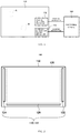
- Fig. 1 is a conceptual diagram illustrating an information processing system 100.
- the information processing system 100 has an input section 110 and a processing section 160, and the input section 110 has a position detection mechanism 112 and a biometric information reading mechanism 114.
- the input section 110 has a surface and allows a user to contact or approximate a position specifier, such as a finger, to the surface for information input.
- the position detection mechanism 112 detects the position of the position specifier on the surface, and the biometric information reading mechanism 114 reads biometric information of the user.
- the processing section 160 performs processing based on the information input to the input section 110.
- the position detection mechanism 112 detects the region A and transmits the position information of the detected region A to the processing section 160.
- the biometric information reading mechanism 114 reads the biometric information from the body of the user, such as the fingerprint of the finger approximated or contacted to the region A and transmits the biometric information thus read to the processing section 160.
- the position information of the region B is transmitted to the processing section 160, and at the same time, the biometric information of the user is transmitted to the processing section 160.
- Fig. 2 is a diagram illustrating an example of the input section 110
- Fig. 3 is a partial enlarged view of the input section 110.
- the input section 110 illustrated in Figs. 2 and 3 is illustrated as an example of the position detection mechanism 112 and the biometric information reading mechanism 114, where the position detection mechanism 112 is exemplified by a device causing the biometric information reading mechanism 114 to function with reduced reading accuracy.
- the input section 110 has a detection element formation region 120, vertical driver formation regions 122 and 124, and a signal readout circuit formation region 126, where the vertical driver formation regions 122 and 124 are arranged respectively to the right and left of the detection element formation region 120 and the signal readout circuit formation region 126 is arranged below the detection element formation region 120. It should be noted that the above expressions of the right and left and above and below merely express the directions in Fig. 2 and do not mean directions in an actual product.
- detection elements 120a In the detection element formation region 120, detection elements 120a, first lines 120b, and second lines 120c are formed.
- vertical driver formation regions 122 and 124 respective vertical drivers 122a and 124a are formed.
- signal readout circuit formation region 126 signal readout circuits 126a are formed.
- the detection elements 120a are arranged in a matrix on a surface of the input section 110 and are exemplified by, for example, photosensitive thin-film transistors. To obtain fingerprint image data with a resolution for personal identification, the detection elements 120a are preferably arranged with a pitch of, for example, 50 ⁇ m approximately.
- the first lines 120b connect the detection elements 120a in a first direction and the second lines 120c connect the detection elements 120a in a second direction different from the first direction.
- the first lines 120b connect gate electrodes of the detection elements 120a in a horizontal row to each other and are connected to the vertical drivers 122a.
- the first lines 120b also connect source electrodes (or drain electrodes) of the detection elements 120a in a horizontal row to each other and are connected to the vertical drivers 124a.
- the second lines 120c connect drain electrodes (or source electrodes) of the detection elements 120a in a vertical row to each other and are connected to the signal readout circuits 126a.
- Figs. 4 and 5 are diagrams illustrating functions of the information processing system 100.
- the processing section 160 narrows down a region to be read by the biometric information reading mechanism 114 based on the position information of the position specifier obtained from the position detection mechanism 112 and activates the biometric information reading mechanism 114 in the reading region thus narrowed down to obtain the biometric information. That is, when a user contacts a finger as the position specifier to the region A, the processing section 160 causes the position detection mechanism 112 to specify the region A to narrow down the region to be read by the biometric information reading mechanism 114 to the region A and causes the biometric information reading mechanism 114 to be activated in the region A to obtain the biometric information.
- the processing section 160 obtains the position information of the position specifier (e.g., a finger of the user) by the position detection mechanism 112, as illustrated in Fig. 4 , the detection elements 120a are activated only on horizontal coarse lines 128 prepared by reducing the first lines 120b and vertical coarse lines 130 prepared by reducing the second lines 120c to obtain the region A as the position information. Then, first lines 132 in the region A and second lines 134 in the region A are activated to obtain detailed fingerprint image data in the region A. That is, functioning the first lines 120b and the second lines 120c by reducing them allows the biometric information reading mechanism 114 to function as the position detection mechanism 112.
- the detection elements 120a are activated only on horizontal coarse lines 128 prepared by reducing the first lines 120b and vertical coarse lines 130 prepared by reducing the second lines 120c to obtain the region A as the position information.
- first lines 132 in the region A and second lines 134 in the region A are activated to obtain detailed fingerprint image data in the region A. That is, functioning the first lines 120b
- first lines 120b and the second lines 120c Functioning the first lines 120b and the second lines 120c by reducing them thus allows the biometric information reading mechanism 114 to function as the position detection mechanism 112 and detailed fingerprint image data to be obtained in the region narrowed down by the position detection mechanism 112 to obtain image data clearly in a short time with a resolution for personal identification at an arbitrary position in a large area region.
- the detailed image data for personal identification is obtained only in a recommended region, allowing image data for personal identification to be obtained efficiently with no waste.
- the detection elements 120a, the first lines 120b, and the second lines 120c formed in the detection element formation region 120, the vertical drivers 122a and 124a formed in the vertical driver formation regions 122 and 124, and the signal readout circuits 126a formed in the signal readout circuit formation region 126 form the biometric information reading mechanism 114 and some of them also form the position detection mechanism 112.
- the position detection mechanism 112 may be expressed as a mechanism configured to cause the biometric information reading mechanism 114 to function with reduced reading accuracy.
- both the first lines 120b and the second lines 120c are reduced in the operation of the processing section 160, it should be noted that only either the first lines 120b or the second lines 120c may be reduced to function.
- Fig. 6 is a diagram illustrating another example of the input section 110.
- the input section 110 illustrated in Fig. 6 has a touch screen 140 as the position detection mechanism 112.
- the touch screen 140 allows detection of the position of the position specifier, such as a finger of the user, and reading of the biometric information by narrowing down to the position.
- the detection elements 120a, the first lines 120b, and the second lines 120c formed in the detection element formation region 120, the vertical drivers 122a and 124a formed in the vertical driver formation regions 122 and 124, and the signal readout circuits 126a formed in the signal readout circuit formation region 126 form the biometric information reading mechanism 114.
- Fig. 7 is a diagram illustrating still another example of the input section 110.
- the input section 110 illustrated in Fig. 7 has a plurality of imaging devices 150 as the position detection mechanism 112.
- Each imaging device 150 takes an image of a region 152 different from each other on the surface of the input section 110. Detecting in which region 152 corresponding to each imaging device 150 the position specifier, such as a finger of the user, is located allows detection of the position of the position specifier and reading of the biometric information by narrowing down to the position.
- the detection elements 120a and the like formed in the detection element formation region 120 may be the biometric information reading mechanism 114, it should be noted that the image data taken by the imaging device 150 may be used as the fingerprint image data for obtaining the biometric information. In this case, the imaging device 150 also functions as the biometric information reading mechanism 114. When used as the biometric information reading mechanism 114, the imaging device 150 is preferably provided with a prism to contact a finger and the like. Although the case of the plurality of imaging devices 150 is described above as an example, a single imaging device 150 may be applied when the imaging device 150 is capable of covering the entire area of the input section 110 by adjusting the direction of imaging, the depth of focus, and the like.
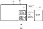
- Fig. 8 is a conceptual diagram illustrating an information processing system 200.
- the information processing system 200 has, in addition to a display section 210, the same configuration as the information processing system 100 in the first embodiment. The description on the same configuration as the information processing system 100 is omitted.
- the display section 210 is a display device, such as a liquid crystal display device and an electroluminescent display device, and is arranged facing the input section 110.
- the input section 110 is transparent or semitransparent to allow a user to visually recognize the display contents of the display section 210 through the input section 110.
- the processing section 160 is provided with, in addition to the functions described in the first embodiment, a function to control the display section 210.
- the processing section 160 performs next processing based on the position information of the position specifier obtained from the position detection mechanism 112 and the user attribute information, for example user identification information, associated with the biometric information obtained from the biometric information reading mechanism 114.
- the processing section 160 selects and performs a function in accordance with the attribute information (e.g., payment processing in accordance with the user identification) among functions assigned to the position of the display section 210 specified in the position information (e.g., function of product selection in a shopping site and seat selection in a ticket reservation site). Specific examples are described below.
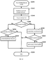
- Figs. 9 , 12 , 15 , and 18 are flow charts illustrating processing of the information processing system 200.
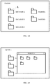
- Figs. 10, 11 , 13, 14 , 16, 17 , 19, and 20 are diagrams illustrating examples of a display of the information processing system 200.
- a login screen is displayed as illustrated in Fig. 10 (S222), and for example, a user contacts a finger to the region A to perform touch detection and fingerprint identification (S224).
- S224 touch detection and fingerprint identification
- a menu screen as illustrated in Fig. 11 is displayed (S228).
- the process goes back to the login screen at S222.
- menus of, for example, "Folder”, “Shopping”, and “Seat Reservation” are displayed and the process is branched to folder processing (S232), shopping processing (S234), and seat reservation processing (S236) in accordance with menu selection (S230) by the user.
- the process is terminated (S238).
- the menu selection by the user is performed by, for example, contacting a finger of the user to any of the menu regions. For example, when the contacted region A is in a display region for the folder processing as illustrated in Fig. 11 , the folder processing is selected.
- Fig. 12 is an example of a process flow when the folder processing is selected.
- a folder selection screen is displayed (S242) as illustrated in Fig. 13 and touch detection is performed by, for example, contacting a finger to the region A by the user (S244).
- fingerprint identification is performed (S248).
- the identification is passed in the fingerprint identification is determined (S250), and when the identification is passed, the selected exclusive A folder is opened (S252) as illustrated in Fig. 14 .
- the process is terminated (S258).
- the selected folder is determined not as an exclusive folder at S246, whether it is a shared folder is determined (S254).
- a selection folder is then opened (S256) when it is a shared folder, while the process is terminated (S258) when it is not.
- one operation of contacting a finger (folder selection) by the user simultaneously allows selecting a folder and obtaining image data for passing the personal identification and thus allows the process to be performed without requesting data input and the like of the user for personal identification even when the selected folder is an exclusive folder.
- the process flow seen by the user is extremely smooth and it is thus possible to provide good user experience.
- Fig. 15 is an example of a process flow when the shopping processing is selected.
- a product selection screen is displayed (S262) as illustrated in Fig. 16 and touch detection and fingerprint identification are performed by, for example, contacting a finger to the region A by the user (S264).
- touch detection and fingerprint identification are performed by, for example, contacting a finger to the region A by the user (S264).
- Whether the identification is passed in the fingerprint identification is determined (S266), and when the identification is passed, a product at a touched position is selected (S268) and product purchase processing and payment processing are performed (S270).
- a purchase confirmation screen is then displayed (S272) and the process is terminated (S274).
- the identification is determined not to be passed at S266, the process is terminated (S274).
- one operation of contacting a finger (product selection) by the user simultaneously allows selecting a product and obtaining image data for passing the personal identification and thus allows the process to be performed without requesting data input and the like of the user for user identification in the payment processing during the product purchase.
- the process flow seen by the user is extremely smooth and it is thus possible to provide good user experience.
- Fig. 18 is an example of a process flow when the reservation processing is selected.
- a seat selection screen is displayed (S278) as illustrated in Fig. 19 and touch detection and fingerprint identification are performed by, for example, contacting a finger to the region A by the user (S280).
- Whether the identification is passed in the fingerprint identification is determined (S282), and when the identification is passed, a seat "B9" at a touched position is selected (S284) and seat reservation processing and payment processing are performed (S286).
- a reservation confirmation screen is then displayed (S288) and the process is terminated (S290).
- the identification is determined not to be passed at S282, the process is terminated (S290).
- one operation of contacting a finger (seat selection) by the user simultaneously allows selecting a seat and obtaining image data for passing the personal identification and thus allows the process to be performed without requesting data input and the like of the user for user identification in the payment processing during the seat reservation.
- the process flow seen by the user is extremely smooth and it is thus possible to provide good user experience.
- the information processing system 200 in the second embodiment does not require a user to input data for personal identification during access to a personally exclusive file, product purchase, and seat reservation and thus allows smooth progress of a series of process flow in file operation, a reservation site, and an electronic commerce site to achieve excellent user experience.
- the position specifier is not limited to this example.
- the body for biometric identification is not limited to this example.
Landscapes
- Engineering & Computer Science (AREA)
- Theoretical Computer Science (AREA)
- Physics & Mathematics (AREA)
- General Engineering & Computer Science (AREA)
- General Physics & Mathematics (AREA)
- Human Computer Interaction (AREA)
- Health & Medical Sciences (AREA)
- Life Sciences & Earth Sciences (AREA)
- Multimedia (AREA)
- Computer Security & Cryptography (AREA)
- Veterinary Medicine (AREA)
- Pathology (AREA)
- General Health & Medical Sciences (AREA)
- Public Health (AREA)
- Surgery (AREA)
- Molecular Biology (AREA)
- Medical Informatics (AREA)
- Heart & Thoracic Surgery (AREA)
- Biomedical Technology (AREA)
- Animal Behavior & Ethology (AREA)
- Biophysics (AREA)
- Computer Hardware Design (AREA)
- Software Systems (AREA)
- Image Input (AREA)
- Collating Specific Patterns (AREA)
- Measurement Of The Respiration, Hearing Ability, Form, And Blood Characteristics Of Living Organisms (AREA)
- User Interface Of Digital Computer (AREA)
- Hardware Redundancy (AREA)
- Small-Scale Networks (AREA)
- Computer And Data Communications (AREA)
Abstract
Description
- The present invention relates to an information processing system.
-
PTL 1 discloses an imaging device to obtain an optical image of a subject, particularly to an imaging device suitable for obtaining a fingerprint image for personal identification. A fingerprint at a fingertip may have low ridges depending on a person, and in such a case, a fingerprint reader is sometimes not capable of obtaining fingerprint image data, or even when being capable of obtaining, the obtained data is sometimes not clear. The imaging device inPTL 1, however, is supposed to achieve an object of the invention to "allow clear imaging of a subject" by providing a configuration of "an imaging device, configured to obtain an optical image of a subject (e.g., a fingertip) from below a contact surface that contacts the subject, wherein a light diffusing film to diffuse light is formed on the contact surface". -
PTL 2 discloses a contact sensor to sense a test object. Similar to the case ofPTL 1 above, a fingerprint reader is sometimes not capable of obtaining fingerprint image data, or even when being capable of obtaining, the obtained data is sometimes not clear. The contact sensor inPTL 2, however, is supposed to achieve an object of the invention to "allow clear imaging of a subject" by providing a configuration of "a contact sensor, configured to sense a test object placed on a placement surface, wherein a liquid repellent coating is formed on the placement surface". - In sites to reserve tickets for hotels, flights, and the like and electronic commerce sites for purchase of goods and the like, personal identification is generally required for, in addition to login to start providing the service, an important procedure such as a payment procedure during a series of process of reservation or purchase of goods.
-
- PTL 1:
JP 2004-39909 A - PTL 2:
JP 2004-178166 A - Use of the techniques described in
PTLs - However, the inventions described in
PTLs - For example, to obtain fingerprint image data with a resolution equivalent to
PTLs - It is an object of the present invention to provide a technique capable of obtaining image data for personal identification clearly in a short time at an arbitrary position in an area region about several times greater than a fingertip. It is another object of the present invention to provide a technique capable of obtaining image data for personal identification efficiently with no waste in an area region about several times greater than a fingertip.
- As described above, reservation sites or electronic commerce sites may require personal identification every time a user selects a process of an important procedure, such as payment processing. The security of transactions is thus ensured by requiring personal identification every time processing an important procedure.
- However, it is not convenient for the user required to provide personal identification for each important procedure due to interruption of a series of process flow for reservation or shopping. In addition, shopping in electronic commerce is, no different from shopping in a real store, to enjoy shopping and thus process interruption in a series of procedures by personal identification is not preferred from the perspective of user experience.
- It is thus still another object of the present invention to provide a technique capable of smooth progress of a series of process flow in a reservation site or an electronic commerce site for excellent user experience.
- To achieve the above problems, a first aspect of the present invention provides an information processing system, including: an input section having a surface and configured to allow a user to contact or approximate a position specifier to the surface for information input; and a processing section configured to perform processing based on the information input to the input section, wherein the input section includes a position detection mechanism configured to detect a position of the position specifier on the surface and a reading mechanism configured to read biometric information of the user.
- The above information processing system may have a configuration in which the processing section narrows down a region to be read by the reading mechanism based on position information of the position specifier obtained from the position detection mechanism and activates the reading mechanism in the reading region to obtain the biometric information.
- The above information processing system may have another configuration in which the processing section configured to perform next processing based on position information of the position specifier obtained from the position detection mechanism and attribute information of the user associated with the biometric information obtained from the reading mechanism. In this case, the above information processing system may further include a
display section 210 arranged facing the input section, wherein the processing section selects and performs, in the next processing, a function in accordance with the attribute information among functions assigned to the position of thedisplay section 210 specified in the position information. - The above information processing system may have a configuration in which the position detection mechanism is a device configured to cause the reading mechanism to function with reduced reading accuracy, a touch screen, or a single or a plurality of imaging devices. In this case, the above information processing system may have a configuration in which the reading mechanism has detection elements arranged in a matrix on the surface, first lines connecting the detection elements in a first direction, and second lines connecting the detection elements in a second direction different from the first direction and is configured to cause the reading mechanism to function as the position detection mechanism by reducing the first lines, the second lines, or both the first lines and the second lines during their function. The above information processing system may have another configuration in which the position detection mechanism is the plurality of imaging devices, and each of the imaging devices takes an image of a region different from each other on the surface.
- The above information processing system may have a configuration in which the biometric information is a pattern or a feature corresponding to a single or a plurality of biometric areas selected from a fingerprint, a vein pattern, face, an iris, and a voiceprint of the user.
- It should be noted that the summary of the invention described above does not list all characteristics necessary for the present invention. In addition, subcombinations of the groups of characteristics may also be the invention.
-
-
Fig. 1 is a conceptual diagram illustrating aninformation processing system 100. -
Fig. 2 is a diagram illustrating an example of aninput section 110. -
Fig. 3 is a partial enlarged view of theinput section 110. -
Fig. 4 is a diagram illustrating functions of theinformation processing system 100. -
Fig. 5 is a diagram illustrating functions of theinformation processing system 100. -
Fig. 6 is a diagram illustrating another example of theinput section 110. -
Fig. 7 is a diagram illustrating still another example of theinput section 110. -
Fig. 8 is a conceptual diagram illustrating aninformation processing system 200. -
Fig. 9 is a flow chart illustrating processing of theinformation processing system 200. -
Fig. 10 is a diagram illustrating an example of a display of theinformation processing system 200. -
Fig. 11 is a diagram illustrating an example of a display of theinformation processing system 200. -
Fig. 12 is a flow chart illustrating processing of theinformation processing system 200. -
Fig. 13 is a diagram illustrating an example of a display of theinformation processing system 200. -
Fig. 14 is a diagram illustrating an example of a display of theinformation processing system 200. -
Fig. 15 is a flow chart illustrating processing of theinformation processing system 200. -
Fig. 16 is a diagram illustrating an example of a display of theinformation processing system 200. -
Fig. 17 is a diagram illustrating an example of a display of theinformation processing system 200. -
Fig. 18 is a flow chart illustrating processing of theinformation processing system 200. -
Fig. 19 is a diagram illustrating an example of a display of theinformation processing system 200. -
Fig. 20 is a diagram illustrating an example of a display of theinformation processing system 200. - The present invention is described below with reference to embodiments while the following embodiments do not limit the invention defined in the appended claims. Not all combinations of the characteristics described in the following embodiments are essential to the solutions of the invention.
-
Fig. 1 is a conceptual diagram illustrating aninformation processing system 100. Theinformation processing system 100 has aninput section 110 and aprocessing section 160, and theinput section 110 has aposition detection mechanism 112 and a biometricinformation reading mechanism 114. - The
input section 110 has a surface and allows a user to contact or approximate a position specifier, such as a finger, to the surface for information input. Theposition detection mechanism 112 detects the position of the position specifier on the surface, and the biometricinformation reading mechanism 114 reads biometric information of the user. Theprocessing section 160 performs processing based on the information input to theinput section 110. - For example, when the user approximates or contacts, for example, a finger (position specifier) to a region A, the
position detection mechanism 112 detects the region A and transmits the position information of the detected region A to theprocessing section 160. The biometricinformation reading mechanism 114 reads the biometric information from the body of the user, such as the fingerprint of the finger approximated or contacted to the region A and transmits the biometric information thus read to theprocessing section 160. When the user approximates or contacts a finger to a region B, the position information of the region B is transmitted to theprocessing section 160, and at the same time, the biometric information of the user is transmitted to theprocessing section 160. -
Fig. 2 is a diagram illustrating an example of theinput section 110, andFig. 3 is a partial enlarged view of theinput section 110. Theinput section 110 illustrated inFigs. 2 and3 is illustrated as an example of theposition detection mechanism 112 and the biometricinformation reading mechanism 114, where theposition detection mechanism 112 is exemplified by a device causing the biometricinformation reading mechanism 114 to function with reduced reading accuracy. - The
input section 110 has a detectionelement formation region 120, verticaldriver formation regions circuit formation region 126, where the verticaldriver formation regions element formation region 120 and the signal readoutcircuit formation region 126 is arranged below the detectionelement formation region 120. It should be noted that the above expressions of the right and left and above and below merely express the directions inFig. 2 and do not mean directions in an actual product. - In the detection
element formation region 120,detection elements 120a, first lines 120b, and second lines 120c are formed. In the verticaldriver formation regions vertical drivers circuit formation region 126,signal readout circuits 126a are formed. - The
detection elements 120a are arranged in a matrix on a surface of theinput section 110 and are exemplified by, for example, photosensitive thin-film transistors. To obtain fingerprint image data with a resolution for personal identification, thedetection elements 120a are preferably arranged with a pitch of, for example, 50 µm approximately. - The first lines 120b connect the
detection elements 120a in a first direction and the second lines 120c connect thedetection elements 120a in a second direction different from the first direction. For example, as illustrated inFig. 3 , the first lines 120b connect gate electrodes of thedetection elements 120a in a horizontal row to each other and are connected to thevertical drivers 122a. The first lines 120b also connect source electrodes (or drain electrodes) of thedetection elements 120a in a horizontal row to each other and are connected to thevertical drivers 124a. The second lines 120c connect drain electrodes (or source electrodes) of thedetection elements 120a in a vertical row to each other and are connected to thesignal readout circuits 126a. -
Figs. 4 and 5 are diagrams illustrating functions of theinformation processing system 100. In theinformation processing system 100, theprocessing section 160 narrows down a region to be read by the biometricinformation reading mechanism 114 based on the position information of the position specifier obtained from theposition detection mechanism 112 and activates the biometricinformation reading mechanism 114 in the reading region thus narrowed down to obtain the biometric information. That is, when a user contacts a finger as the position specifier to the region A, theprocessing section 160 causes theposition detection mechanism 112 to specify the region A to narrow down the region to be read by the biometricinformation reading mechanism 114 to the region A and causes the biometricinformation reading mechanism 114 to be activated in the region A to obtain the biometric information. - For example, at the point when the
processing section 160 obtains the position information of the position specifier (e.g., a finger of the user) by theposition detection mechanism 112, as illustrated inFig. 4 , thedetection elements 120a are activated only on horizontalcoarse lines 128 prepared by reducing the first lines 120b and verticalcoarse lines 130 prepared by reducing the second lines 120c to obtain the region A as the position information. Then,first lines 132 in the region A andsecond lines 134 in the region A are activated to obtain detailed fingerprint image data in the region A. That is, functioning the first lines 120b and the second lines 120c by reducing them allows the biometricinformation reading mechanism 114 to function as theposition detection mechanism 112. - Functioning the first lines 120b and the second lines 120c by reducing them thus allows the biometric
information reading mechanism 114 to function as theposition detection mechanism 112 and detailed fingerprint image data to be obtained in the region narrowed down by theposition detection mechanism 112 to obtain image data clearly in a short time with a resolution for personal identification at an arbitrary position in a large area region. In addition, the detailed image data for personal identification is obtained only in a recommended region, allowing image data for personal identification to be obtained efficiently with no waste. - In the above case, the
detection elements 120a, the first lines 120b, and the second lines 120c formed in the detectionelement formation region 120, thevertical drivers driver formation regions signal readout circuits 126a formed in the signal readoutcircuit formation region 126 form the biometricinformation reading mechanism 114 and some of them also form theposition detection mechanism 112. Theposition detection mechanism 112 may be expressed as a mechanism configured to cause the biometricinformation reading mechanism 114 to function with reduced reading accuracy. - Although the example has been described that both the first lines 120b and the second lines 120c are reduced in the operation of the
processing section 160, it should be noted that only either the first lines 120b or the second lines 120c may be reduced to function. -
Fig. 6 is a diagram illustrating another example of theinput section 110. Theinput section 110 illustrated inFig. 6 has atouch screen 140 as theposition detection mechanism 112. Thetouch screen 140 allows detection of the position of the position specifier, such as a finger of the user, and reading of the biometric information by narrowing down to the position. In this case, thedetection elements 120a, the first lines 120b, and the second lines 120c formed in the detectionelement formation region 120, thevertical drivers driver formation regions signal readout circuits 126a formed in the signal readoutcircuit formation region 126 form the biometricinformation reading mechanism 114. -
Fig. 7 is a diagram illustrating still another example of theinput section 110. Theinput section 110 illustrated inFig. 7 has a plurality ofimaging devices 150 as theposition detection mechanism 112. Eachimaging device 150 takes an image of a region 152 different from each other on the surface of theinput section 110. Detecting in which region 152 corresponding to eachimaging device 150 the position specifier, such as a finger of the user, is located allows detection of the position of the position specifier and reading of the biometric information by narrowing down to the position. - Although the
detection elements 120a and the like formed in the detectionelement formation region 120 may be the biometricinformation reading mechanism 114, it should be noted that the image data taken by theimaging device 150 may be used as the fingerprint image data for obtaining the biometric information. In this case, theimaging device 150 also functions as the biometricinformation reading mechanism 114. When used as the biometricinformation reading mechanism 114, theimaging device 150 is preferably provided with a prism to contact a finger and the like. Although the case of the plurality ofimaging devices 150 is described above as an example, asingle imaging device 150 may be applied when theimaging device 150 is capable of covering the entire area of theinput section 110 by adjusting the direction of imaging, the depth of focus, and the like. -
Fig. 8 is a conceptual diagram illustrating aninformation processing system 200. Theinformation processing system 200 has, in addition to adisplay section 210, the same configuration as theinformation processing system 100 in the first embodiment. The description on the same configuration as theinformation processing system 100 is omitted. - The
display section 210 is a display device, such as a liquid crystal display device and an electroluminescent display device, and is arranged facing theinput section 110. Theinput section 110 is transparent or semitransparent to allow a user to visually recognize the display contents of thedisplay section 210 through theinput section 110. - The
processing section 160 is provided with, in addition to the functions described in the first embodiment, a function to control thedisplay section 210. Theprocessing section 160 performs next processing based on the position information of the position specifier obtained from theposition detection mechanism 112 and the user attribute information, for example user identification information, associated with the biometric information obtained from the biometricinformation reading mechanism 114. For example, in the next processing, theprocessing section 160 selects and performs a function in accordance with the attribute information (e.g., payment processing in accordance with the user identification) among functions assigned to the position of thedisplay section 210 specified in the position information (e.g., function of product selection in a shopping site and seat selection in a ticket reservation site). Specific examples are described below. -
Figs. 9 ,12 ,15 , and18 are flow charts illustrating processing of theinformation processing system 200.Figs. 10, 11 ,13, 14 ,16, 17 ,19, and 20 are diagrams illustrating examples of a display of theinformation processing system 200. - In the
information processing system 200, when the process is started (S220), a login screen is displayed as illustrated inFig. 10 (S222), and for example, a user contacts a finger to the region A to perform touch detection and fingerprint identification (S224). When the user is identified by the fingerprint identification (S226), a menu screen as illustrated inFig. 11 is displayed (S228). When not identified, the process goes back to the login screen at S222. On the menu screen inFig. 11 , menus of, for example, "Folder", "Shopping", and "Seat Reservation" are displayed and the process is branched to folder processing (S232), shopping processing (S234), and seat reservation processing (S236) in accordance with menu selection (S230) by the user. After performing the relevant processing, the process is terminated (S238). - The menu selection by the user is performed by, for example, contacting a finger of the user to any of the menu regions. For example, when the contacted region A is in a display region for the folder processing as illustrated in
Fig. 11 , the folder processing is selected. -
Fig. 12 is an example of a process flow when the folder processing is selected. When the folder processing is started (S240), a folder selection screen is displayed (S242) as illustrated inFig. 13 and touch detection is performed by, for example, contacting a finger to the region A by the user (S244). Whether the selected folder is a folder exclusive for the user is determined (S246), and when it is the exclusive folder, fingerprint identification is performed (S248). Whether the identification is passed in the fingerprint identification is determined (S250), and when the identification is passed, the selected exclusive A folder is opened (S252) as illustrated inFig. 14 . When the identification is not passed, the process is terminated (S258). When the selected folder is determined not as an exclusive folder at S246, whether it is a shared folder is determined (S254). A selection folder is then opened (S256) when it is a shared folder, while the process is terminated (S258) when it is not. - According to the flow in
Fig. 12 , one operation of contacting a finger (folder selection) by the user simultaneously allows selecting a folder and obtaining image data for passing the personal identification and thus allows the process to be performed without requesting data input and the like of the user for personal identification even when the selected folder is an exclusive folder. As a result, the process flow seen by the user is extremely smooth and it is thus possible to provide good user experience. -
Fig. 15 is an example of a process flow when the shopping processing is selected. When the shopping processing is started (S260), a product selection screen is displayed (S262) as illustrated inFig. 16 and touch detection and fingerprint identification are performed by, for example, contacting a finger to the region A by the user (S264). Whether the identification is passed in the fingerprint identification is determined (S266), and when the identification is passed, a product at a touched position is selected (S268) and product purchase processing and payment processing are performed (S270). As illustrated inFig. 17 , a purchase confirmation screen is then displayed (S272) and the process is terminated (S274). When the identification is determined not to be passed at S266, the process is terminated (S274). - As just described, one operation of contacting a finger (product selection) by the user simultaneously allows selecting a product and obtaining image data for passing the personal identification and thus allows the process to be performed without requesting data input and the like of the user for user identification in the payment processing during the product purchase. As a result, the process flow seen by the user is extremely smooth and it is thus possible to provide good user experience.
-
Fig. 18 is an example of a process flow when the reservation processing is selected. When the reservation processing is started (S276), a seat selection screen is displayed (S278) as illustrated inFig. 19 and touch detection and fingerprint identification are performed by, for example, contacting a finger to the region A by the user (S280). Whether the identification is passed in the fingerprint identification is determined (S282), and when the identification is passed, a seat "B9" at a touched position is selected (S284) and seat reservation processing and payment processing are performed (S286). As illustrated inFig. 20 , a reservation confirmation screen is then displayed (S288) and the process is terminated (S290). When the identification is determined not to be passed at S282, the process is terminated (S290). - As just described, one operation of contacting a finger (seat selection) by the user simultaneously allows selecting a seat and obtaining image data for passing the personal identification and thus allows the process to be performed without requesting data input and the like of the user for user identification in the payment processing during the seat reservation. As a result, the process flow seen by the user is extremely smooth and it is thus possible to provide good user experience.
- As described above, the
information processing system 200 in the second embodiment does not require a user to input data for personal identification during access to a personally exclusive file, product purchase, and seat reservation and thus allows smooth progress of a series of process flow in file operation, a reservation site, and an electronic commerce site to achieve excellent user experience. - Although the present invention has been described with reference to the above embodiments, the technical scope of the present invention is not limited to the scope of the above embodiments. It will become apparent to those skilled in the art that the above embodiments may be variously modified or improved. From the appended claims, it will be apparent that the technical scope of the present invention may include such modified or improved embodiments.
- For example, although exemplified by a finger of the user in the above embodiments, the position specifier is not limited to this example. In addition, although exemplified by a fingerprint of the user, the body for biometric identification is not limited to this example. For example, it is possible to use, as the biometric information, a pattern or a feature corresponding to a single or a plurality of biometric areas selected from a fingerprint, a vein pattern, the face, an iris, and a voiceprint of the user.
- It should be noted that the order of performing each process of the operations, the procedures, the steps, the stages, and the like in the devices, the systems (, programs), and the methods in the appended claims, the description, and the drawings may be achieved in an arbitrary order unless explicitly indicated as "before", "prior to", and the like in particular or unless using an output of previous processing for later processing. Even when the operation flow in the claims, the description, and the drawings is described for convenience using "first", "then", and the like, it does not mean execution in this order is essential.
-
- 100
- Information Processing System,
- 110
- Input Section,
- 112
- Position Detection Mechanism,
- 114
- Biometric Information Reading Mechanism,
- 120
- Detection Element Formation Region,
- 120a
- Detection Element,
- 120b
- First Line,
- 120c
- Second Line,
- 122, 124
- Vertical Driver Formation Region,
- 122a, 124a
- Vertical Driver,
- 126
- Signal Readout Circuit Formation Region,
- 126a
- Signal Readout Circuit,
- 128
- Horizontal Coarse Line,
- 130
- Vertical Coarse Line,
- 132
- First Line in Region A,
- 134
- Second Line in Region A,
- 140
- Touch Screen,
- 150
- Imaging Device,
- 152
- Region,
- 160
- Processing Section,
- 200
- Information Processing System,
- 210
- Display Section.
Claims (8)
- An information processing system, comprising:an input section having a surface and configured to allow a user to contact or approximate a position specifier to the surface for information input; anda processing section configured to perform processing based on the information input to the input section, whereinthe input section includesa position detection mechanism configured to detect a position of the position specifier on the surface anda reading mechanism configured to read biometric information of the user.
- The information processing system according to Claim 1, wherein
the processing section narrows down a region to be read by the reading mechanism based on position information of the position specifier obtained from the position detection mechanism and
activates the reading mechanism in the reading region to obtain the biometric information. - The information processing system according to Claim 1 or 2, wherein
the processing section configured to perform next processing based on position information of the position specifier obtained from the position detection mechanism and attribute information of the user associated with the biometric information obtained from the reading mechanism. - The information processing system according to Claim 3, further comprising a display section 210 arranged facing the input section, wherein
the processing section selects and performs, in the next processing, a function in accordance with the attribute information among functions assigned to the position of the display section 210 specified in the position information. - The information processing system according to any one of Claims 1 through 4, wherein the position detection mechanism is a device configured to cause the reading mechanism to function with reduced reading accuracy, a touch screen, or a single or a plurality of imaging devices.
- The information processing system according to Claim 5, wherein the reading mechanism has detection elements arranged in a matrix on the surface, first lines connecting the detection elements in a first direction, and second lines connecting the detection elements in a second direction different from the first direction and
is configured to cause the reading mechanism to function as the position detection mechanism by reducing the first lines, the second lines, or both the first lines and the second lines during their function. - The information processing system according to Claim 5, wherein the position detection mechanism is the plurality of imaging devices, and
each of the imaging devices takes an image of a region different from each other on the surface. - The information processing system according to any one of Claims 1 through 7, wherein the biometric information is a pattern or a feature corresponding to a single or a plurality of biometric areas selected from a fingerprint, a vein pattern, face, an iris, and a voiceprint of the user.
Applications Claiming Priority (2)
| Application Number | Priority Date | Filing Date | Title |
|---|---|---|---|
| JP2017238177 | 2017-12-12 | ||
| PCT/JP2018/044838 WO2019117002A1 (en) | 2017-12-12 | 2018-12-06 | Information processing system |
Publications (2)
| Publication Number | Publication Date |
|---|---|
| EP3726456A1 true EP3726456A1 (en) | 2020-10-21 |
| EP3726456A4 EP3726456A4 (en) | 2021-08-25 |
Family
ID=66819267
Family Applications (1)
| Application Number | Title | Priority Date | Filing Date |
|---|---|---|---|
| EP18887305.3A Pending EP3726456A4 (en) | 2017-12-12 | 2018-12-06 | INFORMATION PROCESSING SYSTEM |
Country Status (7)
| Country | Link |
|---|---|
| US (1) | US12414712B2 (en) |
| EP (1) | EP3726456A4 (en) |
| JP (1) | JP7344513B2 (en) |
| KR (1) | KR102936065B1 (en) |
| CN (1) | CN112470187A (en) |
| TW (1) | TWI812661B (en) |
| WO (1) | WO2019117002A1 (en) |
Families Citing this family (1)
| Publication number | Priority date | Publication date | Assignee | Title |
|---|---|---|---|---|
| KR102953622B1 (en) | 2021-02-17 | 2026-04-15 | 주식회사 엘지에너지솔루션 | System for detecting defects of electrode tab and method for detecting defects of electrode tab using the same |
Family Cites Families (26)
| Publication number | Priority date | Publication date | Assignee | Title |
|---|---|---|---|---|
| JP2004039909A (en) | 2002-07-04 | 2004-02-05 | Casio Comput Co Ltd | Imaging device |
| JP2004178166A (en) | 2002-11-26 | 2004-06-24 | Casio Comput Co Ltd | Contact type sensor |
| JP2004334788A (en) | 2003-05-12 | 2004-11-25 | Minoru Ikeda | Personal identification system, authentication device, personal identification method, program, and recording medium |
| JP4266363B2 (en) | 2004-09-27 | 2009-05-20 | 日本開閉器工業株式会社 | Pressure sensitive fingerprint sensor |
| JP2007264498A (en) * | 2006-03-29 | 2007-10-11 | Kyocera Corp | Imaging lens, optical module, and portable terminal |
| JP4919684B2 (en) * | 2006-03-30 | 2012-04-18 | 日立オムロンターミナルソリューションズ株式会社 | Biometric authentication apparatus and automatic transaction apparatus using the same |
| JP2007293539A (en) | 2006-04-24 | 2007-11-08 | Matsushita Electric Ind Co Ltd | Input device |
| JP5228439B2 (en) | 2007-10-22 | 2013-07-03 | 三菱電機株式会社 | Operation input device |
| JP5521304B2 (en) | 2008-10-03 | 2014-06-11 | 富士通株式会社 | Imaging apparatus, imaging program, imaging method, authentication apparatus, authentication program, and authentication method |
| CN102934058A (en) * | 2009-11-17 | 2013-02-13 | Rpo私人有限公司 | Apparatus and method for receiving touch input |
| JP4911395B1 (en) * | 2010-09-28 | 2012-04-04 | Necエンジニアリング株式会社 | Image reading device |
| WO2014061097A1 (en) * | 2012-10-16 | 2014-04-24 | 三菱電機株式会社 | Information display device and display information operation method |
| WO2014098133A1 (en) * | 2012-12-19 | 2014-06-26 | 株式会社デンソーウェーブ | Information code, information code generation method, information code reader device, and information code usage system |
| US9176614B2 (en) * | 2013-05-28 | 2015-11-03 | Google Technology Holdings LLC | Adapative sensing component resolution based on touch location authentication |
| US10116868B2 (en) | 2014-04-28 | 2018-10-30 | Qualcomm Incorporated | Display-integrated user-classification, security and fingerprint system |
| US9886613B2 (en) * | 2014-07-07 | 2018-02-06 | Shenzhen GOODIX Technology Co., Ltd. | Integration of touch screen and fingerprint sensor assembly |
| CN105528099B (en) * | 2014-09-29 | 2018-04-13 | 神盾股份有限公司 | Electronic device combining fingerprint identification function with touch screen and control method thereof |
| JP6055459B2 (en) * | 2014-12-17 | 2016-12-27 | 京セラドキュメントソリューションズ株式会社 | Touch panel device and image processing device |
| CN106293277B (en) | 2015-05-11 | 2019-08-30 | 上海和辉光电有限公司 | Full screen fingerprinting method and structure |
| CN104850292B (en) * | 2015-06-01 | 2017-09-29 | 京东方科技集团股份有限公司 | A kind of In-cell touch panel, its driving method and display device |
| CN107004130B (en) | 2015-06-18 | 2020-08-28 | 深圳市汇顶科技股份有限公司 | Optical sensor module under screen for sensing fingerprint on screen |
| JP2017033499A (en) | 2015-08-06 | 2017-02-09 | 株式会社日本総合研究所 | Device and system for biometric authentication-compatible processing and biometric authentication processing program |
| CN106709405B (en) | 2015-11-16 | 2021-01-01 | 小米科技有限责任公司 | Mobile equipment, screen module of mobile equipment, fingerprint acquisition method and device and electronic equipment |
| WO2017110218A1 (en) | 2015-12-25 | 2017-06-29 | シャープ株式会社 | Touch panel controller, touch panel system, and touch panel control method |
| US20180157395A1 (en) * | 2016-12-07 | 2018-06-07 | Lg Electronics Inc. | Mobile terminal and method for controlling the same |
| US10474867B2 (en) * | 2017-09-28 | 2019-11-12 | Apple Inc. | Electronic device including mask collimation and related methods |
-
2018
- 2018-12-06 US US16/772,652 patent/US12414712B2/en active Active
- 2018-12-06 JP JP2019559588A patent/JP7344513B2/en active Active
- 2018-12-06 WO PCT/JP2018/044838 patent/WO2019117002A1/en not_active Ceased
- 2018-12-06 CN CN201880086166.6A patent/CN112470187A/en active Pending
- 2018-12-06 EP EP18887305.3A patent/EP3726456A4/en active Pending
- 2018-12-06 KR KR1020207020026A patent/KR102936065B1/en active Active
- 2018-12-12 TW TW107144684A patent/TWI812661B/en active
Also Published As
| Publication number | Publication date |
|---|---|
| KR102936065B1 (en) | 2026-03-09 |
| US12414712B2 (en) | 2025-09-16 |
| TWI812661B (en) | 2023-08-21 |
| JPWO2019117002A1 (en) | 2021-05-13 |
| CN112470187A (en) | 2021-03-09 |
| US20210278925A1 (en) | 2021-09-09 |
| JP7344513B2 (en) | 2023-09-14 |
| KR20210020860A (en) | 2021-02-24 |
| WO2019117002A1 (en) | 2019-06-20 |
| EP3726456A4 (en) | 2021-08-25 |
| TW201933071A (en) | 2019-08-16 |
Similar Documents
| Publication | Publication Date | Title |
|---|---|---|
| US11475691B2 (en) | Enrollment using synthetic fingerprint image and fingerprint sensing systems | |
| CN109739379B (en) | Display panel, driving method thereof and display device | |
| US20040096086A1 (en) | Information device and display control method | |
| JP2002352234A (en) | Fingerprint sensor and position adjustment device | |
| US11823593B2 (en) | Method for displaying learning content of terminal and application program therefor | |
| CN101452527A (en) | Capacitive fingerprint sensor and panel thereof | |
| US20170322596A1 (en) | Operational Control Method for Flexible Display Device | |
| CN112667212A (en) | Buried point data visualization method and device, terminal and storage medium | |
| JP2023020802A (en) | METHOD AND APPARATUS FOR PROVIDING INFORMATION ON ARTICLES TO USERS | |
| US12414712B2 (en) | Information processing system | |
| CN101473290A (en) | Line shape processing device, line shape processing method, information recording medium, and program | |
| CN112395925A (en) | Under-screen fingerprint registration method and electronic device | |
| JP2009213796A (en) | Ultrasonograph | |
| Sha et al. | Color affects the usability of smart phone icon for the elderly | |
| EP3942456B1 (en) | Enrolment of a fingerprint template | |
| JP2010134699A (en) | Input device, input method and input program | |
| JP6983731B2 (en) | Information processing program, information processing method, terminal device and analysis device | |
| CN109960457A (en) | Information processing method, information processing apparatus, and electronic device | |
| GB2574973A (en) | User interface display method and electronic device | |
| CN111709380B (en) | Optical fingerprint recognition method for screen and related products | |
| JP6883000B2 (en) | Information control program, information control method and information control device | |
| JP3455477B2 (en) | Fingerprint recognition apparatus and data processing method | |
| JP6945477B2 (en) | Information control program, information control method and information control device | |
| US20230267727A1 (en) | Image analysis apparatus, image analysis method, and storage medium | |
| JP6901420B2 (en) | Information control program, information control method and information control device |
Legal Events
| Date | Code | Title | Description |
|---|---|---|---|
| STAA | Information on the status of an ep patent application or granted ep patent |
Free format text: STATUS: THE INTERNATIONAL PUBLICATION HAS BEEN MADE |
|
| PUAI | Public reference made under article 153(3) epc to a published international application that has entered the european phase |
Free format text: ORIGINAL CODE: 0009012 |
|
| STAA | Information on the status of an ep patent application or granted ep patent |
Free format text: STATUS: REQUEST FOR EXAMINATION WAS MADE |
|
| 17P | Request for examination filed |
Effective date: 20200710 |
|
| AK | Designated contracting states |
Kind code of ref document: A1 Designated state(s): AL AT BE BG CH CY CZ DE DK EE ES FI FR GB GR HR HU IE IS IT LI LT LU LV MC MK MT NL NO PL PT RO RS SE SI SK SM TR |
|
| AX | Request for extension of the european patent |
Extension state: BA ME |
|
| DAV | Request for validation of the european patent (deleted) | ||
| DAX | Request for extension of the european patent (deleted) | ||
| A4 | Supplementary search report drawn up and despatched |
Effective date: 20210723 |
|
| RIC1 | Information provided on ipc code assigned before grant |
Ipc: G06T 1/00 20060101AFI20210719BHEP Ipc: A61B 5/1171 20160101ALI20210719BHEP Ipc: G06F 3/041 20060101ALI20210719BHEP Ipc: G06K 9/00 20060101ALI20210719BHEP |
|
| R17P | Request for examination filed (corrected) |
Effective date: 20200710 |
|
| STAA | Information on the status of an ep patent application or granted ep patent |
Free format text: STATUS: EXAMINATION IS IN PROGRESS |
|
| 17Q | First examination report despatched |
Effective date: 20240212 |
|
| REG | Reference to a national code |
Ref country code: DE Ref legal event code: R079 Free format text: PREVIOUS MAIN CLASS: G06T0001000000 Ipc: G06V0040130000 |
|
| GRAP | Despatch of communication of intention to grant a patent |
Free format text: ORIGINAL CODE: EPIDOSNIGR1 |
|
| STAA | Information on the status of an ep patent application or granted ep patent |
Free format text: STATUS: GRANT OF PATENT IS INTENDED |
|
| INTG | Intention to grant announced |
Effective date: 20260120 |
|
| RIC1 | Information provided on ipc code assigned before grant |
Ipc: G06V 40/13 20220101AFI20260109BHEP Ipc: G06F 3/04842 20220101ALI20260109BHEP Ipc: G06F 3/041 20060101ALI20260109BHEP Ipc: A61B 5/1171 20160101ALI20260109BHEP |